1
Agisoft PhotoScan User Manual
Standard Edition, Version 0.9.0
Agisoft PhotoScan User Manual: Standard Edition, Version 0.9.0
Publication date 2012
Copyright © 2012 AgiSoft LLC
Table of Contents
Overview ......................................................................................................................... iv
How it works ............................................................................................................ iv
About the manual ...................................................................................................... iv
1. Installation ..................................................................................................................... 1
System requirements ................................................................................................... 1
OpenCL acceleration ................................................................................................... 1
Installation procedure .................................................................................................. 2
Restrictions of the Demo mode ..................................................................................... 2
2. Capturing photos ............................................................................................................ 4
Basic rules ................................................................................................................ 4
Capturing scenarios ..................................................................................................... 4
Restrictions ............................................................................................................... 5
3. General workflow ........................................................................................................... 7
Loading photos .......................................................................................................... 7
Aligning photos .......................................................................................................... 8
Building model geometry ............................................................................................. 9
Building model texture .............................................................................................. 10
Saving intermediate results ......................................................................................... 12
Exporting results ....................................................................................................... 12
4. Advanced use ............................................................................................................... 15
Splitting project ........................................................................................................ 15
Camera calibration .................................................................................................... 17
Using masks ............................................................................................................ 19
Editing sparse point cloud .......................................................................................... 23
Editing model geometry ............................................................................................. 24
A. Graphical User Interface ................................................................................................ 27
Application Window ................................................................................................. 27
Menu Commands ...................................................................................................... 29
Toolbar Buttons ........................................................................................................ 32
B. Troubleshooting ............................................................................................................ 34
Photo alignment succeeds, but the resulting camera positions appear to be wrong .................. 34
Reconstructed geometry appears to be cut and some important parts are missing ................... 34
The photos included in the project file can't be opened and operations from the Workflow
menu fail ................................................................................................................. 35
iii
Overview
Agisoft PhotoScan is an advanced image-based 3D modeling solution aimed at creating professional
quality 3D content from still images. Based on the latest multi-view 3D reconstruction technology, it
operates with arbitrary images and is efficient in both controlled and uncontrolled conditions. Photos can
be taken from any position, providing that the object to be reconstructed is visible on at least two photos.
Both image alignment and 3D model reconstruction are fully automated.
How it works
Generally the final goal of photographs processing by PhotoScan is to build a textured 3D model. The
procedure of photographs processing and 3D model construction comprises three main stages.
1. The first stage is photographs alignment. At this stage PhotoScan searches for common points on
photographs and matches them, as well as it finds the position of the camera for each picture and refines
camera calibration parameters. As a result a sparse point cloud and a set of camera positions are formed.
The point cloud represents the results of photos alignment and will not be directly used in the further
3D model construction procedure (except for the point cloud based reconstruction method). However
it can be exported for further usage in external programs. For instance, the point cloud model can be
used in a 3D editor as a reference.
On the contrary the set of camera positions is required for further 3D model construction by PhotoScan.
2. The next stage is building geometry. Based on the estimated camera positions and pictures themselves
a 3D polygon mesh, representing the object surface, is build by PhotoScan. Four algorithmic methods
available in PhotoScan can be applied to 3D mesh generation: Arbitrary - Smooth, Arbitrary - Sharp,
Height field - Smooth and Height field - Sharp methods. Additionally there is a Point Cloud based
method for fast geometry generation based on the sparse point cloud alone.
Having built the mesh, it may be necessary to edit it. Some corrections, such as mesh decimation,
removal of detached components, closing of holes in the mesh, etc. can be performed by PhotoScan.
For more complex editing you have to engage external 3D editor tools. PhotoScan allows to export the
mesh, edit it by another software and import it back.
3. After the geometry (i.e. the mesh) is constructed, it can be textured and / or used for orthophoto
generation. Several texturing modes are available in PhotoScan, they are described in the corresponding
section of this manual.
About the manual
Basically, the sequence of axtions described above covers most of the model processing needs. All these
operations are carried out automatically according to the parameters set by user. Instructions on how to
get through these operations and descriptions of the parameters controlling each step are explained in the
corresponding sections of the Chapter 3, General workflow.
In some cases, however, additional actions may be required to get the desired results. For instance, pictures
taken using uncommon lenses such as fish-eyes may require preliminary calibration of optical system
parameters. In some capturing scenarios masking of certain regions of the photos may be required to
exclude them from the calculations. All these advanced functions are described in the Chapter 4, Advanced
use.
iv
Overview
It can take up quite a long time to reconstruct a 3D model. PhotoScan allows to export obtained results
and save intermediate data in a form of project files at any stage of the process. If you are not familiar with
the concept of projects, its brief description is given at the end of the Chapter 3, General workflow.
In the manual you can also find instructions on the PhotoScan installation procedure and basic rules for
taking "good" photographs, i.e. pictures that provide most necessary information for 3D reconstruction.
v
Chapter 1. Installation
System requirements
Minimal configuration
• Windows XP or later (32 or 64 bit), Mac OS X Snow Leopard or later, Debian / Ubuntu (64 bit)
• Intel Core 2 Duo processor or equivalent
• 2GB of RAM
Recommended configuration
• Windows XP or later (64 bit), Mac OS X Snow Leopard or later, Debian / Ubuntu (64 bit)
• Intel Core i7 processor
• 12GB of RAM
The number of photos that can be processed by PhotoScan depends on the available RAM and
reconstruction parameters used. Assuming that a single photo resolution is of the order of 10 MPx, 2GB
RAM is sufficient to make a model based on 20 to 30 photos. 12GB RAM will allow to process up to
200-300 photographs.
OpenCL acceleration
PhotoScan supports accelerated geometry reconstruction due to exploiting of the graphics hardware
(GPU).
NVidia
GeForce 8xxx series and later.
ATI
Radeon HD 5xxx series and later.
PhotoScan allegedly is able to utilize processing power of any OpenCL enabled device, provided that
OpenCL drivers for the device are properly installed. However, due to the large number of various
combinations of video chips, driver versions and operating systems, we are unable to test and guarantee
PhotoScan's compatibility with every device and on every platform.
The table below lists currently supported devices (on Windows platform only). We will pay particular
attention to possible problems with PhotoScan running on these devices.
Table 1.1. Supported Desktop GPUs on Windows platform
NVIDIA
AMD
GeForce GTX 680
Radeon HD 7970
GeForce GTX 580
Radeon HD 6970
GeForce GTX 570
Radeon HD 6950
1
Installation
NVIDIA
AMD
GeForce GTX 560
Radeon HD 6870
GeForce GTX 480
Radeon HD 5870
GeForce GTX 470
Radeon HD 5850
GeForce GTX 465
Radeon HD 5830
GeForce GTX 285
GeForce GTX 280
Although PhotoScan is supposed to be able to utilize other GPU models and on other operating systems
than Windows, we do not guarantee that it will work correctly.
Note
• OpenCL acceleration can be enabled using OpenCL tab in the Preferences dialog box.
• Using OpenCL acceleration with mobile video chips is not recommended because of the low
performance of mobile GPUs.
Installation procedure
Installing PhotoScan on Microsoft Windows
To install PhotoScan on Microsoft Windows simply run the downloaded msi file and follow the
instructions.
Installing PhotoScan on Mac OS X
Open the downloaded dmg image and drag PhotoScan application to the desired location on your hard
drive.
Installing PhotoScan on Debian/Ubuntu
Unpack the downloaded archive with a program distribution kit to the desired location on your hard drive.
Start PhotoScan by running photoscan.sh script from the program folder.
Restrictions of the Demo mode
Once PhotoScan is downloaded and installed on your computer you can run it either in the Demo mode
or in the full function mode. At every run until you enter a serial number it will show a registration box
offering two options: (1) use PhotoScan in the Demo mode or (2) enter the serial number to confirm the
purchase. The first choice is set by default, so if you are still exploring PhotoScan click the Continue button
and PhotoScan will start in the Demo mode.
The employment of PhotoScan in the Demo mode is not time limited. Several functions, however, are not
available in the Demo mode. These functions are the following:
• saving the project;
• exporting reconstruction results (you can only view a 3D model on the screen).
2
Installation
To use PhotoScan in the full function mode you have to purchase it. On purchasing you will get the serial
number to enter into the registration box on starting PhotoScan. Once the serial number is entered the
registration box will not appear again and you will get full access to all functions of the program.
3
Chapter 2. Capturing photos
Before loading your photographs into PhotoScan you need to take them and select those suitable for 3D
model reconstruction.
Photographs can be taken by any standard digital camera, as long as you follow some specific capturing
guidelines. This section explains the general principles of taking and selecting pictures that provide the
most appropriate data for 3D model generation.
Basic rules
• Use a digital camera with reasonably high resolution (5 MPix or more).
• Wide angle lenses suit better for reconstructing spatial relations between objects than telephoto ones.
• Avoid not textured and flat objects or scenes.
• Avoid shiny and transparent objects.
• Avoid unwanted foregrounds and moving objects as much as possible.
• Shoot shiny objects under a cloudy sky.
• Shoot pictures of the scene with a lot of overlap.
• Capture most important scene content from multiple viewpoints (3 or more).
• Do not crop or geometrically transform the images.
• More photos is better than not enough.
• Spending some time planning your shot might be very useful.
• Make sure to study the following schemes and read the list of restrictions before you get out for shooting
photographs.
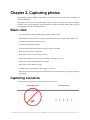
Capturing scenarios
The following figures represent several typical capturing scenarios:
Facade (Incorrect)
Facade (Correct)
4
Capturing photos
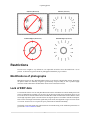
Interior (Incorrect)
Interior (Correct)
Isolated Object (Incorrect)
Isolated Object (Correct)
Restrictions
In some cases it might be very difficult or even impossible to build a correct 3D model from a set of
pictures. A short list of typical reasons for photographs unsuitability is given below.
Modifications of photographs
PhotoScan can process only unmodified photos as they were taken by a digital photo camera. Processing
the photos which were manually cropped or geometrically warped is likely to fail or produce highly
inaccurate results. Photometric modifications do not affect reconstruction results.
Lack of EXIF data
To estimate the field of view for each photo PhotoScan uses the information saved in the EXIF part of each
picture. If EXIF data are available you can expect to get the best possible 3D reconstruction. However 3D
scene can also be reconstructed in the absence of EXIF data. In this case PhotoScan assumes that the 35mm
focal length equivalent equals to 50 mm and tries to align the photos in accordance with this assumption.
If the correct focal length value differs significantly from 50 mm, the alignment can give incorrect results
or even fail. In such cases it is required to specify initial camera calibration manually.
The details of necessary EXIF tags and instructions for manual setting of the calibration parameters are
given in the Camera calibration section
5
Capturing photos
Lens distortion
The distortion of the lens being used to capture the photos should be well modeled using the Brown's
distortion model. Otherwise it is almost impossible to build a precise 3D model. Fish eyes and ultrawide angle lenses are poorly modeled by the distortion model implemented, which leads to inaccurate
reconstructions.
6
Chapter 3. General workflow
The processing of images by PhotoScan includes the following main steps:
• loading photos into PhotoScan;
• inspecting loaded images, removing unnecessary images;
• aligning photos;
• building 3D model;
• editing 3D model;
• exporting results.
If you are using PhotoScan in the full function (not the Demo) mode, intermediate results of the image
processing can be saved at any stage in the form of project files and can be used later. The concept of
projects and project files is briefly explained in the Saving intermediate results section.
The list above represents all the necessary steps involved in the construction of a textured 3D model from
your photos. Some additional tools, which you may find to be useful, are described in the Chapter 4,
Advanced use.
Loading photos
Before starting any operation it is necessary to point out what photos will be used as a source for 3D
reconstruction. In fact, photographs themselves are not loaded into PhotoScan until they are needed. So,
when you "load photos" you only indicate photographs that will be used for further processing.
To load a set of photos
1.
Select Add Photos... command from the Workflow menu or click
Add Photos toolbar button.
2.
In the Add Photos dialog box browse to the folder containing the images and select files to be
processed. Then click Open button.
3.
Selected photos will appear on the Workspace pane.
Note
• PhotoScan accepts the following image formats: JPEG, TIFF, PNG, BMP, PPM, OpenEXR
and JPEG Multi-Picture Format (MPO). Photos in any other format will not be shown in the
Add Photos dialog box. To work with such photos you will need to convert them in one of the
supported formats.
If you have loaded some unwanted photos, you can easily remove them at any moment.
To remove unwanted photos
1.
On the Workspace pane select the photos to be removed.
2.
Right-click on the selected photos and choose Remove Items command from the opened context
menu, or click
working set.
Remove Items toolbar button. The selected photos will be removed from the
7
General workflow
Inspecting the loaded photos
Loaded photos are displayed on the Workspace pane along with flags reflecting their status.
The following flags can appear next to the photo name:
NC (Not calibrated)
Notifies that the EXIF data available is not sufficient to estimate the camera focal length. In this case
PhotoScan assumes that the corresponding photo was taken using 50mm lens (35mm film equivalent).
If the actual focal length differs significantly from this value, manual calibration may be required.
More details on manual camera calibration can be found in the Camera calibration section.
NA (Not aligned)
Notifies that external camera orientation parameters were not estimated for the current photo yet.
Images loaded to PhotoScan will not be aligned until you perform the next step - photos alignment.
Aligning photos
Once photos are loaded into PhotoScan, they need to be aligned. At this stage PhotoScan finds the camera
position for each photo and builds a point cloud model.
To align a set of photos
1.
Select Align Photos... command from the Workflow menu.
2.
In the Align Photos dialog box select the desired alignment options. Click OK button when done.
3.
The progress dialog box will appear displaying the current processing status. To cancel processing
click Cancel button.
Alignment having been completed, computed camera positions and a sparse point cloud will be displayed.
You can inspect alignment results and remove incorrectly positioned photos, if any. To see the matches
between any two photos use View Matches... command from the Tools menu.
The point cloud and estimated camera positions can be exported for processing with another software if
needed.
Incorrectly positioned photos can be realigned.
To realign a subset of photos
1.
Reset alignment for incorrectly positioned photos using Reset Photo Alignment command from the
photo context menu.
2.
Select photos to be realigned and use Align Selected Photos command from the photo context menu.
3.
The progress dialog box will appear displaying the current processing status. To cancel processing
click Cancel button.
Alignment parameters
The following parameters control the photo alignment procedure and can be modified in the Align Photos
dialog box:
8
General workflow
Accuracy
Higher accuracy setting helps to obtain more accurate camera position estimates. Lower accuracy
setting can be used to get the rough camera positions in a shorter period of time.
Pair preselection
The alignment process of large photo sets can take a long time. A significant portion of this time period
is spent on matching of detected features across the photos. Image pair preselection option may speed
up this process due to selection of a subset of image pairs to be matched. In the Generic preselection
mode the overlapping pairs of photos are selected by matching photos using lower accuracy setting
first.
Constrain features by mask
When this option is enabled, features detected in the masked image regions are discarded. For
additional information on the usage of masks please refer to the Using masks section.
Building model geometry
3D model reconstruction is a computationally intensive operation and can take a long time, depending on
the quantity and resolution of loaded photos. It is recommended to build a model with the lowest quality
first to estimate the applicability of the chosen reconstruction method, and then to recompute the results
using a higher quality setting. It is also recommended to save the project before building the geometry.
To build a 3D model
1.
Check the reconstruction volume bounding box. To adjust the bounding box use the
Resize Region
and
Rotate Region toolbar buttons. Rotate the bounding box and then drag corners of the box to
the desired positions. If the Height field reconstruction method is applied, the red side of the
bounding box will define the reconstruction plane. In this case make sure that the bounding box is
correctly oriented.
2.
Select the Build Geometry... command from the Workflow menu.
3.
In the Build Geometry dialog box select the desired reconstruction parameters. Click OK button when
done.
4.
The progress dialog box will appear displaying the current processing status. To cancel processing
click Cancel button.
Reconstruction methods
PhotoScan supports several reconstruction methods and settings, which help to produce optimal
reconstructions for a given data set.
Object type
Arbitrary
Arbitrary object type can be used for modeling of any kind of object. It should be selected for
closed objects, such as statues, buildings, etc. It doesn't make any assumptions on the type of the
object modeled, which comes at a cost of higher memory consumption.
Height field
The Height field object type is optimized for modeling of planar surfaces, such as terrains or basreliefs. It should be selected for aerial photography processing as it requires lower amount of memory
and allows for larger data sets processing.
9
General workflow
Geometry type
Sharp
Sharp geometry type option leads to more accurate reconstruction results and does not introduce
extra geometry, like hole filling "patches". Manual hole filling is usually required at the post
processing step.
Smooth
Smooth geometry type option produces watertight reconstructions with no or little holes on resulting
surface. Large areas of extra geometry might be generated with this method, but they could be easily
removed later using selection and cropping tools. Smooth setting is recommended for orthophoto
generation.
Reconstruction parameters
Quality
Specifies the desired reconstruction quality. Higher quality settings can be used to obtain more detailed
and accurate geometry, but require longer time for processing. Point Cloud quality setting is
used for fast 3D model generation based solely on the sparse point cloud. The option is available for
Smooth geometry type only.
Face count
Specifies the maximum face count in the final mesh. 0 - if no decimation is required.
Filter threshold
Specifies the maximum face count of small connected components to be removed after surface
reconstruction (in percent of the total face count). The 0 value disables connected component filtering.
Hole threshold (Height field methods only)
Specifies the maximum size of holes to be filled after surface reconstruction (in percent of the total
surface area). The 0 value disables automatic hole filling.
Note
• PhotoScan tends to produce 3D models with excessive geometry resolution, so it is recommended
to perform mesh decimation after geometry computation. More information on mesh decimation
and other 3D model geometry editing tools is given in the Editing model geometry section.
Building model texture
To generate 3D model texture
1.
Select Build Texture... command from the Workflow menu.
2.
Select the desired texture generation parameters in the Build Texture dialog box. Click OK button
when done.
3.
The progress dialog box will appear displaying the current processing status. To cancel processing
click Cancel button.
Texture mapping modes
The texture mapping mode determines how the object texture will be packed in the texture atlas. Proper
texture mapping mode selection helps to obtain optimal texture packing and, consequently, better visual
quality of the final model.
10
General workflow
Generic
The default mode is the Generic mapping mode; it allows to parameterize texture atlas for arbitrary
geometry. No assumptions regarding the type of the scene to be processed are made; program tries
to create as uniform texture as possible.
Adaptive orthophoto
In the Adaptive orthophoto mapping mode the object surface is split into the flat part and
vertical regions. The flat part of the surface is textured using the orthographic projection, while vertical
regions are textured separately to maintain accurate texture representation in such regions. When in
the Adaptive orthophoto mapping mode, program tends to produce more compact texture
representation for nearly planar scenes, while maintaining good texture quality for vertical surfaces,
such as walls of the buildings.
Orthophoto
In the Orthophoto mapping mode the whole object surface is textured in the orthographic
projection. The Orthophoto mapping mode produces even more compact texture representation
than the Adaptive orthophoto mode at the expense of texture quality in vertical regions.
Single photo
The Single photo mapping mode allows to generate texture from a single photo. The photo to
be used for texturing can be selected from Texture from list.
Keep uv
The Keep uv mapping mode generates texture atlas using current texture parameterization. It can
be used to rebuild texture atlas using different resolution or to generate the atlas for the model
parametrized in the external software.
Texture generation parameters
The following parameters control various aspects of texture atlas generation:
Texture from (Single photo mapping mode only)
Specifies the photo to be used for texturing. Available only in the Single photo mapping mode.
Blending mode (not used in Single photo mode)
Selects the way how pixel values from different photos will be combined in the final texture.
Average - uses the average value of all pixels from individual photos.
Mosaic - gives more quality for orthophoto and texture atlas than Average mode, since it does not
mix image details of overlapping photos but uses more appropriate photo. Mosaic texture blending
mode is especially useful for orthophoto generation based on approximate geometric model.
Max Intensity - the photo which has maximum intensity of the corresponding pixel is selected.
Min Intensity - the photo which has minimum intensity of the corresponding pixel is selected.
Fill holes
Enables hole filling for contiguous, orthophoto-like texture generation. Recommended for use only
combined with Height-field geometry reconstruction mode. It is recommended to disable hole filling
option when texturing stand-alone objects reconstructed in Arbitrary mode.
Atlas width
Specifies the width of the texture atlas in pixels.
Atlas height
Specifies the height of the texture atlas in pixels.
11
General workflow
Color depth
Specifies the target texture color depth (Standard or HDR). HDR texture generation requires HDR
photos on input.
Saving intermediate results
Certain stages of 3D model reconstruction can take a long time. The full chain of operations could easily
last for 4-6 hours when building a model from hundreds of photos. It is not always possible to finish all
the operations in one run. PhotoScan allows to save intermediate results in a project file.
PhotoScan project files may contain the following information:
• List of loaded photographs with reference paths to the image files.
• Photo alignment data such as information on camera positions, point cloud model and set of refined
camera calibration parameters for each photo.
• Masks applied to the photos in project.
• Reconstructed 3D model with any changes made by user. This includes geometry and texture if they
were built.
• Structure of the project, i.e. number of chunks in the project and their content.
You can save the project at the end of any processing stage and return to it later. To restart work simply
load the corresponding file into PhotoScan. Project files can also serve as backup files or be used to save
different versions of the same model.
Project files use relative paths to reference original photos. Thus, when moving or copying the project file
to another location do not forget to move or copy photographs with all the folder structure involved as
well. Otherwise, PhotoScan will fail to run any operation requiring source images, although the project
file including the reconstructed model will be loaded up correctly.
Exporting results
PhotoScan supports export of processing results in various representations.
Point clouds and camera calibration data can be exported right after photo alignment is completed. All
other export options are available after the geometry is built.
In some cases editing model geometry in the external software may be required. PhotoScan supports model
export for editing in external software and then allows to import it back, as it is described in the Editing
model geometry section of the manual.
Point Cloud export
To export sparse or dense point cloud
1.
Select Export Points... command from the File menu.
2.
Browse the destination folder, choose the file type, and print in the file name. Click Save button.
3.
In the Export Points dialog box set the Point Cloud value for the Quality parameter if you need to
export sparse point cloud. To export a dense point cloud choose an approprite quality among the rest
of the values.
12
General workflow
4.
Indicate export parameters applicable to the selected file type.
5.
Click OK button to start export.
6.
The progress dialog box will appear displaying the current processing status. To cancel processing
click Cancel button.
In some cases it may be reasonable to edit sparse point cloud before exporting it. To read about point cloud
edititing refer to the Editing sparse point cloud section of the manual.
PhotoScan supports point cloud export in the following formats:
• Wavefront OBJ
• Stanford PLY
• XYZ text file format
• ASPRS LAS
Note
• Saving color information of the point cloud is supported by the PLY, TXT and LAS file formats.
• Saving point normals information is supported by the OBJ, PLY and TXT file formats.
Camera calibration and positions data export
To export camera calibration and positions data select Export Cameras... command from the Tools menu.
To export / import only camera calibration data select Camera Calibration... command from the Tools
menu.
PhotoScan supports camera data export in the following formats:
• PhotoScan structure file format (XML based)
• Bundler OUT file format
• CHAN file format
• Boujou TXT file format
• Omega Phi Kappa text file format
Note
• Camera data export in Bundler and Boujou file formats will save sparse point cloud data in the
same file.
• Camera data export in Bundler file format would not save distortion coefficient k3.
3D model export
To export 3D model
1.
Select Export Model... command from the File menu.
13
General workflow
2.
Browse the destination folder, choose the file type, and print in the file name. Click Save button.
3.
In the Export Model dialog indicate export parameters applicable to the selected file type.
4.
Click OK button to start export.
5.
The progress dialog box will appear displaying the current processing status. To cancel processing
click Cancel button.
Note
• If the model is referenced in local coordinates, PhotoScan can write a KML file for the exported
model to be correctly located on Google maps.
PhotoScan supports model export in the following formats:
• Wavefront OBJ
• 3DS file format
• VRML
• COLLADA
• Stanford PLY
• Autodesk DXF
• U3D
• Adobe PDF
Some file formats (OBJ, 3DS, VRML, COLLADA, PLY) save texture image in a separate file. The texture
file should be kept in the same directory as the main file describing the geometry. If the texture atlas was
not built only the model geometry is exported.
14
Chapter 4. Advanced use
Splitting project
In some cases it is very hard or even impossible to generate 3D model of the whole object in one go. This
could happen for instance if the total amount of photographs is too large to be processed. To overcome
this PhotoScan offers the possibility of splitting the set of photos in several separate "chunks" within the
project. The alignment of photos, building geometry and forming the texture atlas may be performed on
each chunk separately and then the resulting 3D models may be combined together.
Working with chunks is no more difficult than using PhotoScan following the general workflow. In fact,
in PhotoScan always exists at least one active chunk and all the 3D model processing workflow operations
are applied to this chunk.
To work with several chunks you need to know how to create chunks and how to combine resulting 3D
models from separate chunks into one model.
Creating a chunk
To create new chunk click on the
Add Chunk toolbar button on the Workspace pane or select Add
Chunk command from the Workspace context menu (available by right-clicking on the root element in
the Workspace pane).
After the chunk is created you may load photos in it, align them, generate mesh surface model, build texture
atlas, export the models at any stage and so on. The models in the chunks are not linked with each other.
To move photos from one chunk to another simply select them in the list of photos on the Workspace pane,
and then drag and drop in the desirable chunk.
Working with chunks
All operations within the chunk are carried out following the common workflow: loading photographs,
aligning them, building geometry model, building texture atlas, exporting 3D model and so on.
Note that all these operations are applied to the active chunk. When a new chunk is created it is activated
automatically. Save project operation saves the content of all chunks.
To set another chunk as active
1.
Right-click on the chunk title on the Workspace pane.
2.
Select Set Active command from the context menu.
To remove chunk
1.
Right-click on the chunk title on the Workspace pane.
2.
Select Remove Items command from the context menu.
Aligning chunks
After the "partial" 3D models are built in several chunks they can be merged together. Before merging
the models they need to be aligned.
15
Advanced use
To align models from separate chunks
1.
Select Align Chunks command from the Workflow menu.
2.
In the Align Chunks dialog box select chunks to be aligned, indicate reference chunk with a doubleclick. Set desired alignment options. Click OK button when done.
3.
The progress dialog box will appear displaying the current processing status. To cancel processing
click the Cancel button.
The following parameters control the chunks alignment procedure and can be modified in the Align Chunks
dialog box:
Method
Defines the chunks alignment method. Point based method alignes chunks by matching photos
across the different chunks. Camera based method is used to align chunks based on estimated
camera locations. Corresponding cameras should have the same label.
Accuracy (Point based alignment only)
Higher accuracy setting helps to obtain more accurate chunk alignment results. Lower accuracy setting
can be used to get the rough chunk alignment in the shorter time.
Preselect image pairs (Point based alignment only)
The alignment process of many chunks may take a long time. A signficant portion of this time is spent
for matching of detected features across the photos. Image pair preselection option can speed up this
process by selection of a subset of image pairs to be matched.
Constrain features by mask (Point based alignment only)
When this option is enabled, features detected in the masked image regions are discarded. For
additional information on the usage of masks refer to the Using masks section.
Note
• Chunk alignment can be performed only for chunks containing aligned photos.
• There is no need to perform chunk alignment for georeferenced chunks, as they are already in
the same coordinate frame.
Merging chunks
After alignment is complete the separate models can be merged into a single model.
To merge models
1.
Select Merge Chunks command from the Workflow menu.
2.
In the Merge Chunks dialog box select chunks to be merged and the desired merging options. Click
OK button when done.
3.
PhotoScan will merge the separate chunks into one. The merged chunk will be displayed in the project
content list on Workspace pane.
The following parameters control the chunks merging procedure and can be modified in the Merge Chunks
dialog box:
16
Advanced use
Merge models
Defines if models from the selected chunks are merged.
Chunks merging result (i.e. photos, points and geometry) will be stored in the new chunk and it may be
treated as common chunk (e.g. textured and/or exported).
Batch processing
PhotoScan allows to perform general workflow operations with multiple chunks automatically. It is useful
when dealing with a large number of chunks to be processed.
Batch processing can be applied to all chunks in the Workspace, to unprocessed chunks only, or to the
chunks selected by the user.
Batch processing can perform the following operations:
• Align Photos
• Build Geometry
• Build Texture
• Decimate Mesh
• Import Cameras
• Export Model
• Align chunks
• Save project after every completed operation
To start batch processing
1.
Select Batch Process... command from the Workflow menu.
2.
Click Add to add the desired processing stages.
3.
In the Add Job dialog select the kind of operation to be performed, the list of chunks it should be
applied to, and desired processing parameters. Click OK button when done.
4.
Repeat the previos steps to add other processing steps as required.
5.
Arrange jobs by clicking Up and Down arrows by the right of the Batch Process... dialog box.
6.
Click OK button to start processing.
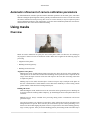
Camera calibration
While carrying out photos alignment PhotoScan estimates both internal and external camera orientation
parameters, including nonlinear radial distortions. For a successful estimation the information on
approximate focal length values is required. Normally this data is extracted automatically from the EXIF
metadata, or the 50mm focal length (35mm film equivalent) is assumed if the EXIF information is
insufficient.
In some cases, the 50mm guess can differ too much from the actual focal length. This can lead to the failure
of the alignment process. In such cases it is required to specify the initial camera calibration manually.
17
Advanced use
To specify camera calibration manually
1.
Select Camera Calibration... command from the Tools menu.
2.
In the Camera Calibration dialog box, select Initial viewing mode. Select the photos to be
calibrated.
3.
Modify the calibration parameters displayed in the corresponding edit boxes. Normally only fx, fy,
cx and cy values should be corrected.
4.
Click Apply button to set the calibration. You will notice that the selected photos will be marked with
the C flag (Custom calibration).
5.
Click Close button to close the camera calibration dialog.
Calibration parameters
fx, fy
Focal length in x- and y-dimensions measured in pixels.
cx, cy
Principal point coordinates, i.e. coordinates of lens optical axis interception with sensor plane.
skew
Skew transformation coefficient.
k1, k2, k3
Radial distortion coefficients.
p1, p2
Tangential distortion coefficients.
How to set up appropriate values
In the case of missing EXIF data or too large lens distortions manual setting of lens calibration may be
required. This may happen if you used an old manual lens which cannot be detected by the camera or if
the photos were taken by the film camera and digitized later. Some hints on selecting suitable calibration
parameters are listed below:
• It is very unlikely that skew transformation coefficient will have non zero value. So its almost always
safe to set skew parameter equal to zero.
• Unless you have used lenses with high distortion, such as fish eyes, the same applies to distortion
coefficients. Leave it zero and PhotoScan will estimate them on its own. If ultra wide or fisheye lens were
used to capture the photos you may try to estimate them using Agisoft Lens utility for lens calibration
(http://www.agisoft.ru/products/lens/).
• fx and fy coefficients are normally equal. They may be different if the pixels of recording media were
not square, which is a very rare case. If you know the focal length of the lens, physical dimension of the
optical sensor and size of picture in pixels you may easily calculate these coefficients as: fx = focal length
in mm * x-dimension of sensor in pixels / x-dimension of sensor in mm. Similar formula applies to fy.
• For conventional (non tilt and shift) lenses the optical axis of the lens is likely to intercept the optical
sensor plane in its geometric center. So for cx and cy coefficient the coordinates of the image center
would be the good guess.
18
Advanced use
Automatic refinement of camera calibration parameters
By default PhotoScan considers specified camera calibration parameters as the initial guess, and refines
them later during the photo alignment. That is generally a desirable behaviour. However in the cases when
the camera calibration is known precisely (like in case of a metric camera), it may be required to protect
camera calibration parameters from optimization. To fix the camera calibration parameters select the Fix
calibration check box in the Camera Calibration dialog.
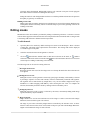
Using masks
Overview
Masks are used in PhotoScan to specify the areas on the photos which can otherwise be confusing to
the program or lead to incorrect reconstruction results. Masks can be applied at the following stages of
processing:
• Alignment of the photos
• Building 3D model geometry
• Building 3D model texture
Alignment of the photos
Masked areas can be excluded during feature point detection. Thus, the objects on the masked parts
of the photos are not taken into account while estimating camera positions. This is important in the
setups, where the object of interest is not static with respect to the scene, like when using a turn table
to capture the photos.
Masking may be also useful when the object of interest occupies only a small part of the photo. In
this case a small number of useful matches can be filtered out mistakenly as a noise among a much
greater number of matches between background objects.
Building 3D model
While building the model, masked areas are not used in the surface generation process. Masking can
be used to reduce the resulting model complexity, by eliminating the areas on the photos that are not
of interest.
Masked areas are always excluded from processing during surface reconstruction and texture
generation stages.
Let's take for instance a set of photos of some object. Along with an object itself on each photo some
background areas are present. These areas may be useful for more precise camera positioning, so it is
better to use them while aligning the photos. However, impact of these areas at the building geometry
stage is exactly opposite. If they are used for building geometry the resulting model will contain object
19
Advanced use
of interest and its background. Background geometry will "consume" some part of mesh polygons
that could be otherwise used for modeling the main object.
Setting the masks for such background areas allows to avoid this problem and increases the precision
and quality of geometry reconstruction.
Building texture atlas
During texture atlas generation, masked areas on the photos are not used for texturing. Masking areas
on the photos that are occluded by outliers or obstacles helps to prevent the "ghosting" effect on the
resulting texture atlas.
Editing masks
Modification of the current mask is performed by adding or subtracting selections. A selection is created
with one of the supported selection tools and is not incorporated in the current mask until it is merged with
a mask using Add Selection or Subtract Selection operations.
To edit the mask
1.
Open the photo to be masked by double clicking on its name on the Workspace / Photo / Ground
Control pane. The photo will be opened in the main window. The existing mask will be displayed
as a shaded region on the photo.
2.
Select the desired selection tool and generate a selection.
3.
Click on
Add Selection toolbar button to add current selection to the mask, or
Subtract
Selection to subtract the selection from the mask.
Invert Selection button allows to invert current
selection prior to adding or subtracting it from the mask.
The following tools can be used for creating selections:
Rectangle selection tool
Rectangle selection tool is used to select large areas or to clean up the mask after other selection tools
were applied.
Intelligent scissors tool
Intelligent scissors is used to generate a selection by specifying its boundary. The boundary is formed
by selecting a sequence of vertices with a mouse, which are automatically connected with segments.
The segments can be formed either by straight lines, or by curved contours snapped to the object
boundaries. To enable snapping, hold Ctrl key while selecting the next vertex. To complete the
selection, the boundary should be closed by clicking on the first boundary vertex.
Intelligent paint tool
Intelligent paint tool is used to "paint" a selection by the mouse, continuously adding small image
regions, bounded by object boundaries.
Magic wand tool
Magic Wand tool is used to select uniform areas of the image. To make a selection with a Magic
Wand tool, click inside the region to be selected.
The range of pixel colors selected by Magic Wand is controlled by the tolerance value. At lower
tolerance values the tool selects fewer colors similar to the pixel you click with the Magic Wand tool.
Higher value broadens the range of colors selected.
20
Advanced use
Note
• To add new area to the current selection hold the Ctrl key during selection of additional area.
• The masks are generated individually for each image. If some object should be masked out, it
should be masked out on all photos, where that object appears.
Loading masks
Masks can be loaded from external sources, as well as generated automatically from background images
if such data is available. PhotoScan supports loading masks from the following sources:
• From alpha channel of the source photos.
• From separate images.
• Generated from background photos based on background differencing technique.
To import masks
1.
Select Import Masks... command from the Tools menu.
2.
In the Import Mask dialog select suitable parameters. Click OK button when done.
3.
When generating masks from separate or background images, the folder selection dialog will appear.
Browse to the folder containing corresponding images and select it.
4.
The progress dialog box will appear displaying the current processing status. To cancel processing
click Cancel button.
The following parameters can be specified during mask import:
Import masks for
Specifies whether masks should be imported for the currently opened photo, active chunk or entire
Workspace.
Current photo - load mask for the currently opened photo (if any).
Active chunk - load masks for active chunk.
Entire workspace - load masks for all chunks in the project.
Method
Specifies the source of the mask data.
From Alpha - load masks from alpha channel of the source photos.
From File - load masks from separate images.
From Background - generate masks from background photos.
Mask file names (not used in From alpha mode)
Specifies the file name template used to generate mask file names. This template can contain special
tokens, that will be substituted by corresponding data for each photo being processed. The following
tokens are supported:
21
Advanced use
{filename} - file name of the source photo without extension.
{fileext} - extension of the source photo.
{camera} - camera label.
{frame} - frame number.
{filenum} - sequential number of the mask being imported.
For example, {filename}_mask.png template can be used if masks are available in PNG format and
have a _mask suffix.
Tolerance (From Background method only)
Specifies the tolerance threshold used for background differencing. Tolerance value should be set
according to the color separation between foreground and background pixels. For larger separation
higher tolerance values can be used.
Created masks can be also saved for external editing or storage.
To export masks
1.
Select Export Masks... command from the Tools menu.
2.
In the Export Mask dialog select suitable parameters. Click OK button when done.
3.
Browse to the folder where the masks should be saved and select it.
4.
The progress dialog box will appear displaying the current processing status. To cancel processing
click Cancel button.
The following parameters can be specified during mask export:
Export masks for
Specifies whether masks should be exported for the currently opened photo, active chunk or entire
Workspace.
Current photo - save mask for the currently opened photo (if any).
Active chunk - save masks for active chunk.
Entire workspace - save masks for all chunks in the project.
File type
Specifies the type of generated files.
Single channel mask image - generates single channel black and white mask images.
Image with alpha channel - generates color images from source photos combined with mask
data in alpha channel.
Mask file names
Specifies the file name template used to generate mask file names. This template can contain special
tokens, that will be substituted by corresponding data for each photo being processed. The following
tokens are supported:
{filename} - file name of the source photo without extension.
22
Advanced use
{fileext} - extension of the source photo.
{camera} - camera label.
{frame} - frame number.
{filenum} - sequential number of the mask being exported.
For example, {filename}_mask.png template can be used to export masks in PNG format with _mask
suffix.
Note
• When importing/exporting mask for the current photo only, PhotoScan will prompt for the actual
image instead of image folder. Mask file names parameter will not be used in this case.
Editing sparse point cloud
The following point cloud editing tools are available in PhotoScan:
• Automatic filtering based on specified criterion
• Manual points removal
Note
• Point cloud editing operation can be undone/redone using Undo/Redo command from the Edit
menu.
Filtering points based on specified criterion
In some cases it may be useful to find out where the points with high reprojection error are located within
the cloud, or remove points representing high amount of noise. Point cloud filtering helps to select such
points, which usually are supposed to be removed.
PhotoScan supports the following criteria for filtering point cloud:
Reprojection error
High reprojection error usually indicates poor localization accuracy of the corresponding point
projections at the point matching step. It is also typical for false matches. Removing such points can
improve accuracy of the subsequent optimization step.
Reconstruction uncertainty
High reconstruction uncertainty is typical for points, reconstructed from nearby photos with small
baseline. Such points can noticably deviate from the object surface, introducing noise in the point
cloud. While removal of such points should not affect the accuracy of optimization, it may be useful
to remove them before building geometry in Point Cloud mode or for better visual appearence of the
point cloud.
To remove points based on specified criterion
1.
2.
Switch to Point Cloud view mode using
Point Cloud toolbar button.
Select Gradual Selection... command from the Edit menu.
23
Advanced use
3.
4.
In the Gradual Selection dialog box specify the criterion to be used for filtering. Adjust the threshold
level using the slider. You can observe how the selection changes while dragging the slider. Click
OK button to finalize the selection.
To remove selected points use Delete Selection command from the Edit menu or click
Selection toolbar button (or simply press Del button on the keyboard).
Delete
Manual points removal
Incorrect points can be also removed manually.
To remove points from the sparse cloud manually
1.
2.
3.
Switch to Point Cloud view mode using
Point Cloud toolbar button.
Select points to be removed using
Rectangle Selection or
Circle Selection tools. To add new
points to the current selection hold the Ctrl key during selection of additional points. To remove some
points from the current selection hold the Shift key during selection of points to be removed.
To delete selected points click the
Delete Selection toolbar button or select Delete Selection
command from the Edit menu. To crop selection to the selected points click the
toolbar button or select Crop Selection command from the Edit menu.
Crop Selection
Editing model geometry
The following mesh editing tools are available in PhotoScan:
• Decimation tool
• Connected component filtering
• Manual face removal
More complex editing can be done in the external 3D editing tools. PhotoScan allows to export mesh and
then import it back for this purpose.
Note
• For face removal operations such as manual face removal and connected component filtering
it is possible to undo the last mesh editing operation. There are Undo/Redo commands in the
Edit menu.
Please note that undo/redo commands are not supported for mesh decimation and this operation
can not be undone.
Decimation tool
Decimation is a tool used to decrease the geometric resolution of the model by replacing high resolution
mesh with a lower resolution one, which is still capable of representing the object geometry with high
accuracy. PhotoScan tends to produce 3D models with excessive geometry resolution, so mesh decimation
is usually a desirable step after geometry computation.
24
Advanced use
The high detailed models may contain hundreds of thousands polygons. While it is acceptable to work
with such a complex models in 3D editor tools, in most conventional tools like Adobe Reader or Google
Earth high complexity of 3D models may noticeably decrease application performance. High complexity
also results in longer time required to build texture and to export model in pdf file format.
In some cases it is desirable to keep as much geometry details as possible like it is needed for scientific and
archive purposes. However, if there are no special requirements it is recommended to decimate the model
down to 100 000 - 200 000 polygons for exporting in PDF, and to 100 000 or even less for displaying in
Google Earth and alike tools.
To decimate 3D model
1.
Select Decimate Mesh... command from the Tools menu.
2.
In the Decimate Mesh dialog box specify the target number of faces, which should remain in the final
model. Click on the OK button to start decimation.
3.
The progress dialog box will appear displaying the current processing status. To cancel processing
click on the Cancel button.
Note
• Texture atlas is discarded during decimation process. You will have to rebuild texture atlas after
decimation is complete.
Connected component filtering
In some cases reconstructed geometry may contain the cloud of small isolated mesh fragments surrounding
the "main" model. Connected component filtering helps to remove small isolated mesh fragments, which
are usually reconstructed incorrectly or are not needed.
To remove small isolated mesh fragments
1.
Select Gradual Selection... command from the Edit menu.
2.
In the Gradual Selection dialog box select the size of isolated components to be removed using the
slider. You can observe how the selection changes while dragging the slider. Click OK button to
finalize the selection.
3.
To remove the selected components use Delete Selection command from the Edit menu or click
Delete Selection toolbar button (or simply press Del button on the keyboard).
Note that PhotoScan always selects the fragments starting from the smallest ones. If the model contains
only one component the selection will be empty.
Manual face removal
Unnecessary and excessive sections of model geometry can be also removed manually.
To remove part of the faces manually
1.
Select rectangle or circle selection tool using
buttons.
25
Rectangle Selection or
Circle Selection toolbar
Advanced use
2.
3.
Make the selection using the mouse. To add new faces to the current selection hold the Ctrl key
during selection of additional faces. To remove some faces from the current selection hold the Shift
key during selection of faces to be removed.
To delete selected faces click the
Delete Selection toolbar button or use Delete Selection command
from the Edit menu. To crop selection to the selected faces click the
or use Crop Selection command from the Edit menu.
Crop Selection toolbar button
To grow or shrink current selection
1.
To grow current selection press PageUp key in the selection mode. To grow selection by even a larger
amount, press PageUp while holding Shift key pressed.
2.
To shrink current selection press PageDown key in the selection mode. To shrink selection by even
a larger amount, press PageDown while holding Shift key pressed.
Editing mesh in the external program
To export mesh for editing in the external program
1.
Select Export Model... command from the File menu.
2.
In the Save As dialog box, specify the desired mesh format in the Save as type combo box. Select the
file name to be used for the model and click Save button.
3.
In the opened dialog box specify additional parameters specific to the selected file format. Click OK
button when done.
To import edited mesh
1.
Select Import Mesh... command from the Tools menu.
2.
In the Open dialog box, browse to the file with the edited model and click Open.
Note
• PhotoScan suppots loading models in Wavefront OBJ and Stanford PLY file formats only. Please
make sure to select one of these file formats when exporting model from the external 3D editor.
26
Appendix A. Graphical User Interface
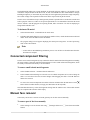
Application Window
General view of application window.
Model view
Model view tab is used for displaying 3D data as well as for 3D model and point cloud editing. The view
of the model depends on the current processing stage and is also controlled by mode selection buttons on
the PhotoScan toolbar.
Model can be shown in textured, solid, shaded, or wireframe mode. Along with the model the results of
photo alignment can be displayed. These include point cloud and camera positions for each photo.
PhotoScan supports the following tools for navigation in the 3D view:
27
Graphical User Interface
Tool
Keyboard modifier
Rotation Tool
Default
Pan Tool
Ctrl key pressed
Zooming Tool
Shift key pressed
All navigation tools are accessible in the navigation mode only. To enter the navigation mode click the
Navigation toolbar button.
Note
• Zooming into the model can be also controlled by the mouse wheel.
Photo view
Photo view tab is used for displaying individual photos as well as masks and markers on them.
Photo view is visible only if any photo is opened. To open the photo double-click on its name on the
Workspace, Ground Control, or Photos pane.
Workspace pane
On the Workspace pane all elements comprising the current project are diplayed. These elements can
include:
• List of chunks in the project
• List of cameras in each chunk
• 3D models in separate chunks
Buttons located on the pane toolbar allow:
• Add chunks
• Add photographs
• Enable or disable certain photographs or chunks for processing at further stages.
• Remove items
Each element in the list is linked with the context menu providing quick access to some common
operations.
Photos pane
Photos pane displays the list of photos / masks / depth maps in the active chunk in the form of thumbnails.
Buttons located on the pane toolbar allow:
• Add cameras
• Enable / disable certain cameras
28
Graphical User Interface
• Remove cameras
• Increase / decrease icons' size
• Switch between types of thumbnailing images
• Filter cameras by feature points
Console pane
Console pane is used for:
• Displaying auxiliary information
• Displaying error messages
Buttons located on the pane toolbar allow:
• Save log
• Clear log
Note
• To open any pane select a corresponding command from the View menu.
Menu Commands
File Menu
Creates an empty PhotoScan project.
New
Opens PhotoScan project file.
Open...
Appends existing PhotoScan project file to the
current one.
Append...
Saves PhotoScan project file.
Save
Saves PhotoScan project file with a new name.
Save As...
Saves 3D model.
Export Model...
Saves sparse / dense point cloud.
Export Points...
Quits the application. Prompts to save active
project.
Exit
Edit Menu
Undo the last editing operation.
Undo
Redo the previously undone editing operation.
Redo
Removes selected faces from the mesh or selected
points from the point cloud.
Delete Selection
29
Graphical User Interface
Edit Menu
Crops selected faces / points.
Crop Selection
Inverts current selection.
Invert Selection
Grows current selection.
Grow Selection
Shrinks current selection.
Shrink Selection
Selects faces/points based on the specified
criterion.
Gradual selection...
View Menu
Displays sparse point cloud reconstructed during
photo alignment.
Point Cloud
Displays 3D model in the shaded mode.
Shaded
Displays 3D model in the solid mode.
Solid
Displays 3D model in the wireframe mode.
Wireframe
Displays 3D model in the textured mode.
Textured
Shows or hides camera positions estimated during
image alignment.
Show Cameras
Shows or hides the trackball.
Show Trackball
Show Info
Shows or hides the mesh information on-screen
display.
Perspective/Orthographic
Switches visualisation view between Perspective
and Orthographic.
Shows or hides Workspace pane.
Workspace
Shows or hides Photos pane.
Photos
Shows or hides Console pane.
Console
Workflow Menu
Add Photos...
Loads additional photos to be processed by
PhotoScan.
Add Folder...
Loads additional photos from folders to be
processed by PhotoScan.
Generates camera positions and sparse point cloud.
Align Photos...
Generates 3D model geometry.
Build Geometry...
Generates 3D model texture.
Build Texture...
Aligns multiple chunks.
Align Chunks
Merges multiple chunks into the single model.
Merge Chunks
30
Graphical User Interface
Workflow Menu
Opens Batch Process dialog box.
Batch Process...
Tools Menu
Decimates mesh to the target face count.
Decimate Mesh...
Closes holes on the model surface.
Close Holes...
Imports edited mesh from the external program.
Import Mesh...
Imports edited texture from the external program.
Import Texture...
Imports camera positions and orientation data.
Import Cameras...
Imports masks or creates mask from alpha channel.
Import Masks...
Exports model texture.
Export Texture...
Exports camera positions and orientation data.
Export Cameras...
Exports masks templates.
Export Mask...
Undistort Photos...
Removes nonlinear distortions by warping source
photos.
View EXIF Data...
Displayes EXIF data for the photos in the active
chunk.
View Matches...
Displayes matches for the photos in the active
chunk.
Collects and displays mesh statistics.
View Mesh Statistics...
Shows camera calibration dialog box.
Camera Calibration...
Shows preferences dialog box.
Preferences...
Photo Menu
Switches to navigation mode.
Navigation
Rectangle selection tool.
Rectangle Selection
Intelligent Scissors selection tool.
Intelligent Scissors
Intelligent Paint selection tool.
Intelligent Paint
Magic Wand selection tool.
Magic Wand
Shows detected features used for alignment of the
current photo.
View Points
Adds current selection to the mask.
Add Selection
Subtracts current selection from the mask.
Subtract Selection
Inverts current selection.
Invert Selection
31
Graphical User Interface
Photo Menu
Resets mask for the current photo.
Reset Mask...
Turns mask shading on or off.
Turn Shading On/Off
Help Menu
Displays help contents.
Contents
Check for Updates...
Checks if PhotoScan update is available for
download.
Activate Product...
Activates / deactivates the product using the
activation key.
About PhotoScan...
Displays program information, version number and
copyright.
Toolbar Buttons
General commands
Creates a new PhotoScan project file.
New
Opens a PhotoScan project file.
Open
Saves a PhotoScan project file.
Save
3D view commands
Navigation tool.
Navigation
Rectangle selection tool.
Rectangle Selection
Circle selection tool.
Circle Selection
Volume selection tool.
Resize region
Volume rotation tool.
Rotate Region
Removes selected faces / points.
Delete Selection
Crops selected faces / points.
Crop Selection
Undo the last editing operation.
Undo
Redo the previously undone editing operation.
Redo
3D view settings
Shows / hides sparse point cloud reconstructed
during image alignment.
Point Cloud
Displays 3D model in the shaded mode.
Shaded
Displays 3D model in the solid mode.
Solid
32
Graphical User Interface
3D view settings
Displays 3D model in the wireframe mode.
Wireframe
Displays 3D model in the textured mode.
Textured
Shows / hides camera positions, reconstructed
during image alignment.
Show Cameras
Shows / hides aligned chunks.
Show Aligned Chunks
Resets model view.
Reset View
Photo view commands
Switches to the navigation mode.
Navigation
Rectangle selection tool.
Rectangle Selection
Intelligent scissors tool.
Intelligent Scissors
Intelligent paint tool.
Intelligent Paint
Magic wand tool.
Magic Wand
Shows / hides feature points used for alignment of
the photo.
View Points
Adds current selection to the mask.
Add Selection
Subtracts current selection from the mask.
Subtract Selection
Inverts current selection.
Invert Selection
Undo the last mask editing operation.
Undo
Redo the previously undone mask editing
operation.
Redo
Rotates the photo clockwise.
Rotate Right
Rotates the photo counterclockwise.
Rotate Left
Increases magnification.
Zoom In
Decreases magnification.
Zoom Out
Turns mask shading on or off.
Turn Shading On/Off
33
Appendix B. Troubleshooting
Photo alignment succeeds, but the resulting
camera positions appear to be wrong
The main reasons for the wrong photo alignment are listed below:
• Small overlap between the photos
• Object movement against the background scene
• Insufficient number of object surface details captured by the camera
• Strong blur or noise on the source photos
To obtain more information about the reason for alignment failure for the specific dataset it may be helpful
to inspect feature points used for alignment of the photos as seen by the PhotoScan algorithms.
To inspect feature points used for alignment
1.
2.
Open the photo to be inspected by double-clicking on its name on the Workspace pane. The photo
will be displayed in the main window.
Switch to the point view mode using
View Points toolbar button. The points used for alignment
of the photo will be overlayed on the image.
Depending on the observed point placement the following recommendations may help to solve the
problem:
Problem
Possible reason
Recommended solution
Not enough points were Low image quality or
Try making better photos with a better camera
used.
too small photo overlap. placement. Pay attention to the camera settings,
like proper level of ISO. Use a tripod if required.
Setting a proper lighting may be also helpful to
capture higher amount of surface details.
The majority of points
used belong to the
background objects.
The object was not static
during capturing or
occupies only a small
area on the photos.
Mask out background regions or consider
shooting another photo set so that the object spans
significant area on the photos. If masking of the
background areas is used, make sure that Constrain
features by mask option in the Align Photos dialog
box is checked.
Reconstructed geometry appears to be cut and
some important parts are missing
Usually this indicates that a wrong reconstruction volume was selected. By default PhotoScan uses an
automatic reconstruction volume selection algorithm, which can produce undesirable selections in some
cases. All object parts outside of the selected reconstruction volume are cropped and are not included in
34
Troubleshooting
the final model. Too large reconstruction volume selections are also undesirable as they result in longer
processing time and greater memory consumption.
To overcome this problem a manual reconstruction volume selection tool should be used.
Note
• The photos must be aligned before the reconstruction volume can be defined.
To select the reconstruction volume manually
1.
Select the manual reconstruction volume selection tool using
Select Volume toolbar button.
2.
Modify the displayed bounding box by dragging the corners of the box to the desired locations.
3.
Before starting to reconstruct geometry make sure that Selection option is chosen from the
Reconstruction volume drop down list.
The photos included in the project file can't
be opened and operations from the Workflow
menu fail
Probably the locations of photos have changed in respect to the location of the project file. The references
to the original photos are stored in the project files in the form of relative paths. These references become
invalid when the project file alone is moved to another location, or when the photos are moved without
changing the project file placement.
To identify the expected photo location
1.
Open the context menu of the photo by right-clicking on its title in the Workspace pane.
2.
Select Show Info... command from the context menu.
3.
A dialog box with information on the selected photo including the path to the image data file will
be displayed.
To fix the problem move the photos to the original locations indicated by the data displayed in the
information dialog box.
If the relative location of the project file in respect to the photos location must be changed, the project file
should be resaved using the Save As... command from the File menu.
To move the project file in respect to the source photo locations
1.
Open the project to be moved using Open... command from the File menu.
2.
Select Save As... command from the File menu. Browse to the folder where the project file should be
placed and specify the destination file name for the project. Click Save button to save the project.
Once the project file was saved to a new location, the original project file can be removed, if necessary.
35