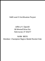
1
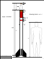
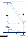
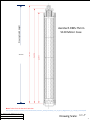
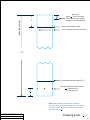
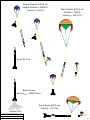
NAR Level 3 Certification Project Jeffery H. Oppold 66 Westall Drive Ext. Richmond, VT 05477 NAR# 88251 Member: Champlain Region Model Rocket Club Overview One of my main interests in High Power Rocketry is the construction and flying of scale models. When searching for a rocket to build, I stumbled upon a scale drawing of the Thiokol Chemical Corporation’s D-Region Tomahawk missile (page 3). After studying this design and the availability of the various components required to construct this rocket, I decided on a 5/9 scale version. The main body tubes will be made from Performance Rocketry’s G12 fiberglass tubing, 3:1 Ogive fiberglass nosecone, and ¼” birch plywood fins reinforced with carbon fiber surfaces. It will use an Aerotech RMS-75mm 5120 Motor Case, which allow for the use of an “L” sized engine for a test flight, as well as an “M” sized motor for the certification flight. The estimated weight loaded is 31.5 lbs, and when launched with an M1500G motor, the rocket should achieve an altitude of ~10500feet. Recovery will use a dual set of PerfectFlite miniAlt/WD logging dual event altimeters. The main chute will be Sky Angel Cert 3 - XLarge, and will provide a rate of decent of ~27 ft/sec. D-REGION TOMAHAWK Overview Jeffery H. Oppold 1 Design Specification D-REGION TOMAHAWK Design Specification Jeffery H. Oppold 3 D-REGION TOMAHAWK Original Blueprint Jeffery H. Oppold 2/25/2012 4 1 163 " 15 167 " 2 18 " Drawing Scale: 0.085" 1" 7" Scale = 0.57222 9 16 1 8 " 2 " 1 18 " 5 325 " 111 18 " 93" 72" D-REGION TOMAHAWK Scaled Blueprint Jeffery H. Oppold 2/25/2012 5 Material = 1 14 " 37° 1 4 Birch Veneer Plywood Carbon Fiber Reinforced (Soller Composites: 6KPW50) " 12° 5 12 " 1 4 1 2 3 4 " " " 16 161 " 5 12 " Fin Tang Width: (5 1 2 5 32 "3 18 " ) / 2 1 641 " 5 34 " " 1 167 " 20° 1 14 " 13 16 " 10° 7 18 " D-REGION TOMAHAWK Fins – 4 Required Jeffery H. Oppold 2/25/2012 Drawing Scale: 1 2 " 1" 6 Drawing Scaled Height Aerotech RMS-75mm 5120 Motor Case 8.225" Note: Taken from the Aerotech web site: http://www.aerotech-rocketry.com/customersite/resource_library/aerotech_rms_ext_dim_dwgs/75mm_hp_rms/hp_75-5120.pdf D-REGION TOMAHAWK RMS-75mm/5120 Motor Case Jeffery H. Oppold 2/25/2012 Drawing Scale: 1.6" 5" 7 Coupler Tube Height Stainless Steel 3/8” EYE-Bolt (McMaster Carr 33045T52) 8-32 Stainless Steel Hex Nuts x 36 (McMaster Carr 90257A009) Top View ABP-1 Bulk Plate Stop Ring 1 ½” Washer 5” Diameter G12 Coupler Tube 10” Long 20° Body Tube Height 10" ¼ Wood Center Ring. G12 Body Tube O.D. 5.150" I .D. 5.0" CR-4 15 78 " O.D. 3.125" I .D. 3.0" CR-3 12 12 " 21" RMS-75mm/5120 Motor Case G12 Motor Tube 75mm Stainless Steel Threaded Rod x4 (McMaster-Carr 98847A009) Drawing Scale: 1.6 " 5 " CR-2 6 14 " Note: Fin Slot is 11 5/8” long starting 1/2 ” from the bottom. Stainless Steel Threaded Insert (McMaster-Carr 90192A114) Note: Fin Fillets are Soller Composite 1” Carbon Fiber Biaxial Braided Tape. Delrin 15/15 Rail Button w/10-24 Screw (x 2) Note: Centering Ring locations with respect to the bottom of the ring. CR-1 3 8 " D-REGION TOMAHAWK Booster Section Jeffery H. Oppold 2/25/2012 Boat-Tail Aero Pack RA75 8 Print out and place tube on top, marking slot location on outside of tube. Fin Slot is 11 5/8” long starting 1/2 ” from the bottom and is ¼” in width. D-REGION TOMAHAWK Fin Slot Alignment Guide Jeffery H. Oppold 2/25/2012 Drawing Scale: 1.0 " 1.0 " 9 Top View O.D. 5.150" I .D. 4.00" O.D. 3.125" Cut Down Cut Out Side View Glue to bottom of CR-1 1" 2 15° D-REGION TOMAHAWK Boat-tail Detail Jeffery H. Oppold 2/25/2012 Cut Down Depth 3" 16 Material = 12 " Birch Veneer Plywood Drawing Scale: 1.0 " 1.0 " 10 Top View Make an Alignment Mark here on all fins. Drill 11/64” Holes D-REGION TOMAHAWK Centering Rings Hole Guide Jeffery H. Oppold 2/25/2012 Drawing Scale: 1.0 " 1.0 " 11 Top View Transfer to Top of CR-1, CR-2, and bottom of CR-3. Placement of 1/6 circle ring used for Rail Guide mount. Center line for threaded insert. D-REGION TOMAHAWK Fin & Rail Guide Alignment Jeffery H. Oppold 2/25/2012 Drawing Scale: 1.0 " 1.0 " 12 Booster Assembly Procedure Fins/Centering Rings Cut the fins out of the Birch Plywood. Carbon Fiber the fins. (Use West System Epoxy/Bondo Filler) Weight/Fin: 7.50oz Weight/Fin: 10.65oz Cut four holes for the 8-32 Threaded Rod in each Centering Ring & Top Bulk Plate. 1Total Weight: 15.0oz Install the threaded inserts for the Aero Pack into CR-1. Cut the Motor Tube to the correct height. Motor Tube Weight: 16.0oz Dry fit in place CR-1, CR-2 , & CR-3 on to the motor tube. Using the template on page 10, mark the fin locations on CR-1, CR-2 & CR-3. Epoxy CR-1 to bottom of the motor tube making sure its location is correct w/r to the Aero Pack. Using the 8-32 Threaded Rod as an alignment aid, epoxy in place CR-2 & CR-3. Using the fin guides, “tack” epoxy the fins (4-Minute JB-Weld) to the motor tube. Verify that each fin is 90° w/r to each fin on its left and right & is 90° w/r to the body tube. Drill the correct size hole in the center of each rail guide ⅙ ring and screw in the threaded inserts. Using Elmer’s Carpenter’s Glue, glue the rail guide ⅙ rings to CR-1 & 4. Clamp until dry. Using Loctite Hysol epoxy, put a good size fillet along each fin/body tube seam. Form the internal fin fillets by using the carbon fiber tape & WS epoxy. Epoxy in place CR-4 but omit the top fillet as the coupler tube needs to fit flush against this ring. Install the threaded rod and nuts. Secure nuts with Loctite Blue 242 Threadlocker. Weigh the final assembly. Weight: 86.0oz Subtract 4 x weight/fin and total weight of the rings from the above measurement. (This is the motor tube/epoxy/carbon fiber/rods/rail guides weight). Updated Motor Tube Weight: 28.4oz Body Tube Cut the body tube to length from 5” G10 Fiber Glass Tubing. Cut the 4: 11 85 " slots for the fins. Fit the final Fin Can assembly inside the booster tube. Mark the rail guide locations on the outside of the body tube. Remove the Fin Can and drill the holes for the retention screws. Weight: 27.00oz 1) Boat Tail, CR-1 & CR-2 weigh 4oz each and CR-3 & CR-4 Weigh 1.5oz each. D-REGION TOMAHAWK Booster Assembly Procedure Jeffery H. Oppold 2/25/2012 13 Booster Assembly Procedure - Continued Final Assembly Epoxy the Fin Can into the Body Tube. Use small C-clamps at the body tube/CR-1 joint. Fill the booster/fin joint with epoxy. Sand smooth. Cut the Bulkhead Stop Ring from scrap 5” tubing and epoxy to the inside top of the coupler ring. Weigh the couple tube and bulk plate. Weight: 20oz Insert the Coupler into the Body tube but do not epoxy at this time. Mount the Bulk Plate and temporary secure with nuts. Insert RMS-75mm/5120 Motor Case. Test fit the motor retention bolt. Remove the Bulk Plate and Motor Case. Epoxy the coupler tube to the body tube. Add a generous fillet of West System Epoxy to the topside of CR-4. Re-attach the Top bulk plate. Epoxy the 1 ½” washer to the top of the bulk plate. Scale Raised Detail Cut the Fin Fillet from hard wood stock and epoxy in place. Cut the body tubing raised details from PML Quantum tubing and epoxy in place. Finish Sanding all surfaces and spray a coat of Krylon Grey Primer. Weigh the final Booster. Weight:144.5oz D-REGION TOMAHAWK Booster Assembly Procedure Jeffery H. Oppold 2/25/2012 14 3 32 " 3 8 " Fin Fillet Cross-sectional Detail Drawing Scale: 1”=1” Fin Fillet End detail 20° 5 16 5 16 1 329 " 5 8 " " " 1 329 " 1 4 " Fin shown for reference. 11 12 " Fin Joint Fin Joint 10 14 " 1" 3 8 " Calculations for Raised Detail Widths: Tube Circumference = 5.15 * 3.14159 = 16.18” Less Fins Width: (0.25” * 4) = 15.18” Final Detail Area: / 4 = 3.795” Less Fin Fillets: (2 * 0.3125”) = 3.17” Want 2:1:2 Detail Width Ratio: /5 = 0.634” Outside Detail Width (0.634 * 2) = 1.268” Inside Detail Width = 0.634” Bottom of Body Tube D-REGION TOMAHAWK Booster Body Tube Raised Detail Jeffery H. Oppold 2/25/2012 Drawing Scale: 1 2 " 1" 15 Raised Detail Templates Print on Card Stock and Cut Out. D-REGION TOMAHAWK Raised Detail Templates Jeffery H. Oppold 2/25/2012 Drawing Scale: 1" 1" 16 2 12 " Body Tube Height Pem Nut Attachment Access Holes 3 Screw holes x 4 16 " (in-line with fins) Avionics Bay Coupler Depth (5½”) 27" 0.125" diameter pressure vent holes. Booster Coupler Height (5”) 6" 4" Sheer Pins 1 " holes, 90° apart. Drill 4 16 Tap for #2-56 Nylon Screws (McMaster-Carr 93135A079) Anti-zipper steel band embedded flush with fiberglass surface. Band is 0.500" wide and 0.025" thick. (Hose clamp band.) D-REGION TOMAHAWK Airframe Mid-Section Jeffery H. Oppold 2/25/2012 Note: With the Booster Section attached, drill the shear pin holes all the way through the airframe and the booster’s coupler tube. Increase the size of the 7 coupler’s hole to 64 ". Drawing Scale: 1 4 " 1" 17 Body Tube Height 1" 4" Sheer Pins 1 Drill 4 16 " holes, 90° apart. Tap for #2-56 Nylon Screws (McMaster-Carr 93135A079) Nose Cone Shoulder Depth 0.125" diameter pressure vent holes. 45" Avionics Bay Coupler Height (5½”) 2 12 " Pem Nut Attachment Access Holes 3 Screw holes x 4 16 " (in-line with fins) Note: With the Nose Cone attached, drill the shear pin holes all the way through the airframe and the Nose Cone’s Shoulder. Increase the size of the 3 shoulder hole to 32 ". D-REGION TOMAHAWK Airframe Upper-Section Jeffery H. Oppold 2/25/2012 Drawing Scale: 1 4 " 1" 18 Air Frame Assembly Procedure Pem Nuts Holes Use the fin alignment guide on page 7 to mark the fin locations at the top of the Mid-Section Air Frame. Extend the marks down 2 ½” from the top of the body tube. Secure the Avionics Bay’s Coupler inside the body tube up to the half way point. Drill the 4 holes for the Pem Nuts through both tubes. Use the fin alignment guide on page 7 to mark the fin locations at the bottom of the Upper-Section Air Frame. Extend the marks up 2 ½” from the bottom of the body tube. Secure the Avionics Bay’s Coupler inside the body tube up to the half way point, taking care to align the fin locations with those on the Mid-Section Air Frame. Drill the 4 holes for the Pem Nuts. Mid-Section Shear Pins/Pressure Vents Draw an alignment mark directly centered between each fin, and make a mark 4” up from the bottom. Drill a shear pin hole and tap, screwing in a shear pin before drilling the next hole. Drill all 4 holes in this sequence. Drill the pressure vent holes. Weigh the final Mid-Section Air Frame Weight: 35.0oz Upper-Section Shear Pins/Pressure Vents Extend the fin alignment marks, drawn in the Pem Nut assembly procedure, down the full length of the tube. Find and mark the center point between each of these marks, 1” down from the top. Drill a shear pin hole and tap, screwing in a shear pin before drilling the next hole. Drill all 4 holes in this sequence. Drill the pressure vent holes. Weigh the final Mid-Section Air Frame Weight: 59.0oz D-REGION TOMAHAWK AirFrame Assembly Procedure Jeffery H. Oppold 2/25/2012 19 Main Chute Charge Holders ABP-3 CBP-2 2 12 " PEM Nuts x 4 (in-line with fins) McMaster-Carr 10-24 94648A350 Threaded Rod (x2) McMaster-Carr: 98804A487 ¼”-20 12” Note: Use JB Weld to secure PEM Nuts to the inside of the Avionic Bay coupler. 11" 5” Diameter G12 Coupler Tube 11” Long PEM Nuts x 4 (in-line with fins) McMaster-Carr 10-24 94648A350 2 12 " Altimeter Sled Retention Nuts CBP-1 ABP-2 Apogee Charge Holders Top and Bottom Charge Holder details are on next two pages. D-REGION TOMAHAWK Avionics Bay Jeffery H. Oppold 2/25/2012 Drawing Scale: 1 2 " 1" 20 Top View Stainless Steel 2” U-Bolt/w Mounting Plate (McMaster Carr 8896T94) Sealing Rubber Washer: McMaster-Carr: 99604A119 11/16” OD Sealing Screw: McMaster-Carr: 98070A470 1” 18-80/10-32 Thread (x2) Terminal Strip: Radio Shack PN# 274-678 (8 Terminals cut down to 2 Side View 1” CPVC End Plug 5” Bulk Plate Rubber Gasket 5” Coupler Bulk Plate D-REGION TOMAHAWK Avionics Bay – Top Jeffery H. Oppold 2/25/2012 Threaded Rod McMaster-Carr: 98804A487 ¼”-20 12” (x2) Drawing Scale: 1" 1" 21 Top View Stainless Steel 2” U-Bolt/w Mounting Plate (McMaster Carr 8896T94) Sealing Rubber Washer: McMaster-Carr: 99604A119 11/16” OD Sealing Screw: McMaster-Carr: 98070A470 1” 18-80/10-32 Thread (x2) ½” CPVC Tubing 2” High Terminal Strip: Radio Shack PN# 274-678 (8 Terminals cut down to 2 Side View ½” CPVC End Plug 5” Bulk Plate 5” Coupler Bulk Plate D-REGION TOMAHAWK Avionics Bay – Bottom Jeffery H. Oppold 2/25/2012 Drawing Scale: 1" 1" 22 Drilling Template #50 Diameter 13/64“ Diameter 1/4“ Diameter 1/8“ Diameter D-REGION TOMAHAWK Avionics Bay – Hole Template Jeffery H. Oppold 2/25/2012 Drawing Scale: 1" 1" 23 Altimeter Sled 5” Diameter G10 Coupler Tube 11” Long + SWITCH Back-Side Mount - " Mounting hole for ALTIMETERONE aLTIMeTeRoNe 1 8 DROUGUE DURACELL® ALKALINE BATTERY MAIN MACH MAIN 1 2 3 4 5 6 7 8 Altimeter PerfectFlite miniAlt/WD (attached using PerfectFlite mounting hardware) MACH MAIN 1 2 3 4 5 6 7 8 DROUGUE ¼” Inside Diameter Brass Tubing MAIN 1 8 " G10 Fiberglass Sheet (7.5” x 4.5”) SWITCH ALKALINE BATTERY DURACELL® miniAlt/WD Front-Side Mount miniAlt/WD Aluminum Bracket for 2-Pole Detent Switch (Aligned with pressure neutralization holes) + " 1” - 3 8 1 2 " 1” Altimeter Sled Retention Nuts Threaded Rod McMaster-Carr: 98804A487 ¼”-20 12” (x2) All Holes are 1 8 " Battery Held on with Plastic Cable Ties Top View D-REGION TOMAHAWK Avionics Bay – Altimeter Sleds Jeffery H. Oppold 2/25/2012 Drawing Scale: 1 2 " 1" 24 Aluminum Bracket Detail 7 64 1 16 " " 1" 1 4 " 1 2 " 1 12 " 14° 1 2 " 1 14 " 3 4 " 1" D-REGION TOMAHAWK Avionics Bay – Altimeter Bracket Jeffery H. Oppold 2/25/2012 Drawing Scale: 1”=1” 25 Primary (1100FT) Main Charge Backup (900FT) Main Charge Avionics' Top Bulkhead DURACELL® miniAlt/WD MAIN MACH 1 2 3 4 5 6 7 8 DROUGUE Missile Works 2-Pole Detent Switch 110 = OFF 220 = ON MAIN 3 SWITCH 2 + 2 - + SWITCH 3 MAIN DROUGUE miniAlt/WD DURACELL® MACH MAIN 1 2 3 4 5 6 7 8 Avionics' Bottom Bulkhead Primary Circuits Wires are Solid Colors Primary Drogue Charge Secondary Circuits Wires are Solid Colors w/Black Stripe Backup (+1 Second) Drogue Charge D-REGION TOMAHAWK Avionics Bay – Schematic Jeffery H. Oppold 2/25/2012 26 Avionics Bay Assembly Procedure Bulk Plates Using the outside edge of the Body Tube Bulk Plate, cut out two gaskets from the gasket material. Using a 4” tube, cutout the center of the gasket. Using CA glue, glue the gaskets to the bulk plates. Epoxy the Coupler Bulk Plates to the Body Tube Bulk Plates, using a bolt through the center holes of the two plates, center the plates and compress the epoxy. Cut out 2 hole drilling templates on page 21. Tape the templates in place over the assembled Bulk Plates and drill the various holes. Assemble and attach the various U-Bolts, wire terminals, and charge holders. Pem Nuts Using a large C Clamp, compress the Pem Nuts in to the Avionics' Coupler Tube. Using JB Weld, epoxy, on the inside of the tube, the Pem Nuts in place. Altimeter Sled Cut the G10 material to the specified dimensions. Using the drilling template supplied with the altimeters, as well as the battery pack and switch bracket, drill the required holes. Cut two pieces of the brass tubing to specified length. Temporarily assemble the two threaded rods through the bulk plates to be used as an alignment aid for attaching the brass tubes to the G10 sled material. Using JB Weld, epoxy the brass tubes to the sled. Note that one tube is on the front, while the other is on the back of sled material. Apply a generous fillet to the joints. Assemble all components onto the Sled and wire per the schematic on page 24. Weigh the assembled Avionics Bay. Weight: 59.0oz D-REGION TOMAHAWK AirFrame Assembly Procedure Jeffery H. Oppold 2/25/2012 27 5” Fiberglass 3:1 Ogive (Performance Rocketry) Garmin Astro DC-40 GP Tracker - see next page for mounting detail. Zinc Plated Coupling Nut ¼”-20 (x4) (McMaster Carr 90264A437) Note: Coupling Nuts are attached with Soller Composite 1” Carbon Fiber Biaxial Braided Tape and Epoxy. CBP3 5” Fiberglass Coupler Bulkhead (Performance Rocketry) ¼”-20 Stainless Steel Pan Head Bolt (McMaster-Carr 91400A257) Stainless Steel 2” U-Bolt/w Mounting Plate (McMaster Carr 8896T94) Bottom View D-REGION TOMAHAWK Nose Cone Jeffery H. Oppold 2/25/2012 Drawing Scale: 1 4 " 1" 28 Garmin Garmin 1 12 " Retention Bolt: M3x16mm 0.50 Pitch D-REGION TOMAHAWK GPS Mounting Scheme Jeffery H. Oppold 2/25/2012 Drawing Scale: 1" 1" 29 Garmin Astro DC-40 Aluminum Mounting Bracket 13 16 " 2" 1 4 1 2 " 1" 1 2 " Holes " 2" 1 8 1" 1 2 1 2 " " 1 8 1 2 1 8 " 1 8 " " " " Holes (Through Both Plates) 1 12 " 1 12 " 1 2 " 1 8 " 2" D-REGION TOMAHAWK GPS Mounting Bracket Jeffery H. Oppold 2/25/2012 Drawing Scale: 1" 1" 30 Nose Cone Assembly Procedure Bulk Plates Drill the four holes in the bulk plate. Use the inside of the shoulder for alignment. Temporary attached the bolts and coupler nuts to the back side of the bulk plate. For each coupler nut, align a flat edge to the outside, flush with the edge of the bulk plate. Using JB Weld epoxy (quick cure), place a small amount on the edge of the coupler nut that is flush with the bulk head outer edge. Slide the assembly inside the nose cone shoulder and allow the epoxy to cure. Carefully remove the bolts and bulk head. The coupler nuts should be perfectly aligned. Using the carbon fiber tape and West System Epoxy thicken to mayonnaise consistency, carefully wrap the tape around the inside of the shoulder covering the coupler nuts. Take care not to the get epoxy on the inside threads of the nuts. Drill the two holes for the U-Bolt. Cut a piece of G10 for the GPS mounting plate. Place the G10 sheet inside the mounting bracket and mark the location of the holes and drill. Using the back piece of the GPS unit, mark where the holes for the attachment screws go and drill. Assemble all components to test for fit and function. Weigh the assembled Nose Cone. Weight: 29.6oz D-REGION TOMAHAWK AirFrame Assembly Procedure Jeffery H. Oppold 2/25/2012 31 Recovery Harness Booster to Mid-Section Drogue Chute Quick Link (3/16” x 2”) Booster Quick Link Mid-Section Quick Link 3” 15’ 45’ Upper-Section to Main Chute Upper-Section Quick Link Main Chute Quick Link 25’ Quick Link/Loop Detail Loops should be tight but still allow for the Quick Links to be removed. Stainless Steel Triangle Quick Link (McMaster Carr 3709T32) Kevlar Thread #69 Double Stitched 3” Folded Over D-REGION TOMAHAWK Recover Harness Jeffery H. Oppold 2/25/2012 I” Kevlar Strap (Wildman Rocketry – KEV1) 1” Fold Under 32 Deployment Bag Protective Flap Folds over to protect Shroud Lines. Bag Opening 25” x 4” Diameter Chute Compartment 1” Wide Elastic Bands Used for Packing Chute Shroud Lines Retention Strap (Connected to Nose Cone) D-REGION TOMAHAWK Deployment Bag Jeffery H. Oppold 2/25/2012 1” Loop Opening 33 Deployment Bag – Parts Detail Bottom Piece (Kevlar Cloth) 6 329 " ½” Seam Allowance Back Side Body Piece (Kevlar Cloth) Retention Strap Blanket Stitch All Edges (Kevlar Strap) 5" 50” Top Side Body Piece 1” Wide Elastic Band 7 ” Long Stitched Outside of Seam Line 20” Blanket Stitch All Edges 1 2 (Kevlar Cloth) 15” Double Stitched down @ 2 323 ” & 4163 ” 1 2 " " 30” 25” Blanket Stitch All Edges 10” ½” Seam Allowance ½” Seam Allowance 5” 0” 7 329 " 7 329 " D-REGION TOMAHAWK Deployment Bag – Parts Detail Jeffery H. Oppold 2/25/2012 34 Deployment Bag – Retention Strap Retention Strap – Loop Detail Kevlar Thread #69 Double Stitched 1” Box Top View 2” Side View 1” Loop 1” Fold Opening Under Loops are sewn on BOTH ENDS. Strap is sewn so that one loop is just inside the bag, with the other loop and the majority of strap is outside of the bag – see next page. D-REGION TOMAHAWK Deployment Bag – Strap Detail Jeffery H. Oppold 2/25/2012 35 Retention Strap should exit between the bottom and back-side pieces’ seam, centered on the back-side piece with one loop just inside the bag. Deployment Bag 1” Wide Elastic Band 6 ” Long Double Stitched down @ 0”, 2 ”,4 ” & 6 ” 9 32 3 32 3 16 9 32 20” Double Stitched 15” Bottom View 25” 10” 5” D-REGION TOMAHAWK Deployment Bag Jeffery H. Oppold 2/25/2012 4” 36 Preparation Stand – Side View 6” Diameter Rocket 5” Diameter Rocket ½” PVC Cap ½” I.D. Pipe Insulation ½” PVC Cross ½” PVC Pipe 6” Long ½” PVC 90° Elbow D-REGION TOMAHAWK Preparation Stand Jeffery H. Oppold 2/25/2012 Drawing Scale: 1 2 " 1" 37 Preparation Stand – Front View ½” PVC Pipe 24” Length – Not Shown to Scale ½” I.D. Pipe Insulation ½” PVC 90° Elbow Parts List: ½” PVC Cross ½” PVC Round Cap ½” PVC 90° Elbow ½” PVC Pipe ½” I.D. Pipe Insulation D-REGION TOMAHAWK Preparation Stand Jeffery H. Oppold 2/25/2012 x 2 x 4 x 4 x 10 ft. x 3 ft. Drawing Scale: 1 2 " 1" 38 Body (Performance Hobby) Airframe: 5.0" Glass Tube – 48” Motor Tube: 3.0" Glass Tube – 48” Booster/AVbay Couplers: 5.0" Glass Coupler – 10” Airframe Bulk Plates: 5.0" Airframe Bulk Plate Coupler Bulk Plates: 5.0" Coupler Bulk Plate Centering Rings: 5.0" to 3.0" CR Nose Cone: 5.0" Ogive 3:1 G12-5.0-48 ($108 x 2) G12-3.0-48 ($68 x 1) G12CT-5.0 ($40 x 2) FBP5.0 ($6 x 3) FCBP5.0 ($6 x 3) FCR45.0-3.0 ($7 x 2) FNC5.0-3-1O ($70 x 1) $216 $ 68 $ 80 $ 18 $ 18 $ 10 $ 70 Aeropack 75mm Retainer: 75mm ASSEMBLY – Flange RA75 ($52 x 1) $ 52 SkyAngle Parachute: CERT-3/Xlarge C3/X ($189 x 1) $189 Kevlar Shock Cord: Shock Cord: In Stock 50’ 1” Kevlar Strap 25’ 1” Kevlar Strap KEV1 KEV1 ($1/ft) ($1/ft) $ 50 $ 25 RT-070 RT-081 ($399) ($ 27) $399 $ 27 Rouse-Tech (Discount Hobby Center) Motor Case: RMS-75mm 5120 Forward Seal Disc RMS-75mm 5120 Carbon Fiber (Soller Composites) Tape: Biaxial Braided Tape 1” x 10’ In Stock 6KPW50 50” x 1 yard Fabric Northern Hardwoods Birch Veneer Plywood ¼” Sheet 5’ x 5’ PerfectFlite Altimeters In Stock(1) miniAlt/WD Hardware Mounting Stand-offs Launch Lugs Unistrut: In Stock Extreme: ($0.94/ft) $9.40 ($31/yard) $ 31 $41.73 MAWD MH44 Rail Buttons (x2) 1515 Delron Rail Buttons (x2) ($100 x 2) $200 ($1.5 x 2) $ 3 ($12/pair) $ 12 ($10/pair) $ 10 D-REGION TOMAHAWK Parts List Jeffery H. Oppold 2/25/2012 39 Stainless Steel (McMaster-Carr) Threaded Rod: 8-32 Thread Size – 36” Hex Nuts: 8-32 Hex Nuts U-Bolt: 2”/Mounting Plate Sheer Pins: 2-56 Nylon Screws Threaded Rod: ¼” – 20 12” PEM Nuts 10-24 Captive Nut Sealing Washer Silicon 11/16” OD Sealing Screw 1” 18-80/10-32 Thread Coupling Nut (Zinc) ¼”-20 1 ½” Length Pan Head Bolt ¼”-20 2”Length Quick Link Triangle Eye Bolt 3/8” - 16 98847A009 90257A009 8896T94 93135A079 98804A487 94648A350 99604A119 98070A470 90264A437 91400A257 3709T32 33045T52 ($2.59 x 4) $10.36 ($8.39 x 100) $ 8.39 ($4.16 x 4) $16.64 ($4.99 x 100) $ 4.99 ($2.41 x 2) $ 4.82 ($6.34 x 10) $ 6.34 ($11.84 x 50) $11.84 ($8.30 x 10) $ 8.30 ($1.80 x 4) $ 7.20 ($5.46 x 10) $ 5.46 ($7.50 x 4) $30.00 ($21.66 x 1) $21.66 Epoxy (McMaster-Carr) High Strength Epoxy: Loctite Hysol E-20hp 6430A19 Applicator Gun: 74695A71 Bayonet Mixer Nozzle: 5.9" L with 1/4" Taper Tip 74695A12 Threadlocker: Loctite® 242, 0.34 oz 91458A112 ($12.16 x 2) ($27.74 x 1) ($0.91 x 12) ($12.39x 1) $24.32 $27.74 $10.92 $12.39 Giant Leap Chute Swivel: In Stock ½” Eyelet – 1500 Ib test ($6.00 x 1) $ 6.00 Custom Made Center Rings: 5.0" to 3.0" ½” Birch Ply ($10.00 x 2) $20.00 D-REGION TOMAHAWK Parts List Jeffery H. Oppold 2/25/2012 40 Construction D-REGION TOMAHAWK Construction Jeffery H. Oppold 41 Fin Construction ¼” Birch Plywood 5’ x 5’ Sheet 5' 20” 5' I had the lumber dealer cut the sheet into 3 20” wide pieces so that I could get it home in my car. My plan is to cut 5 or 6 fins and pick the best of 4 out of them. Note the direction of the wood grain as I’ll want the outside ply’s grain to be perpendicular to the root edge. D-REGION TOMAHAWK Fin Construction Jeffery H. Oppold 2/25/2012 42 Fin Construction – Layout and Rough Cut I cut out a template of the fins from poster board. This allowed for an easy transfer of the fin pattern to the plywood surface. It turned out that I could lay out 2 fins within the 20” height as shown below and saved a lot of material. Cutting was done on a table saw. I don’t own a table saw so I had a friend help me. D-REGION TOMAHAWK Fin Construction Jeffery H. Oppold 2/25/2012 43 Fin Construction – Sanding and Cutting Centering Ring Slots It is most important that all four fins be identical so we aligned the root edges, clamped the 4 fins together, then drilled 3 holes and bolted the fins together. This kept them tightly together when the edges were sanded and the centering rings cut. We decided we needed the holes anyway so that each individual fin could be attached to a guide for cutting the 12° knife edge on the leading edge (see next page). Clamped and on the drill press. After sanding the edges and cutting the slots for the centering rings. D-REGION TOMAHAWK Fin Construction Jeffery H. Oppold 2/25/2012 44 Fin Construction – Cutting the Knife Edge My friend came up with a really good idea on how the hold the fins so that we would get a perfect knife edge. We built a half box as a guide so that we could attach the fins to it, then used the ripping fence to align the box and fin to the blade. Guide box with the fin attached and aligned to the ripping fence. Blade side view. A perfect 12° edge! D-REGION TOMAHAWK Fin Construction Jeffery H. Oppold 2/25/2012 45 Fin Construction – Plywood cuts are Done Here’s a look at the fins after all of plywood cuts have been completed. They each weigh 7.5 ounces. Next step is to fill in the drilled holes, rough edges, and any other imperfections; I’ll use JB Weld for this as I want them good and strong. D-REGION TOMAHAWK Fin Construction Jeffery H. Oppold 2/25/2012 46 Fin Construction – Carbon Fiber Overlay The first step in the carbon fiber process is to cut the carbon fiber cloth into the pattern of the fins. Nice scissors are a must, but it’s actually pretty easy to cut. However, it unravels real easy so I cut the cloth about 1” bigger on each edge and then use masking tape to hold it. That’s me on the floor cutting the carbon fiber cloth. The bolt is 60” wide and expensive so I want to minimize waste. Here’s what the patterned carbon fiber looks like after it’s been cut and the edges taped. I had to cut 8 pieces. D-REGION TOMAHAWK Fin Construction Jeffery H. Oppold 2/25/2012 47 Fin Construction – Carbon Fiber Overlay The second step is to cut the release fabric and batting. The release fabric is placed right on top of the epoxied carbon fiber so that when compressed, the excess epoxy passes through it and is absorbed by the batting, which is placed over the release fabric. Once the epoxy cures, the release fabric is easily peeled off, leaving a smooth a surface. The release fabric is actually harder to cut than the carbon fiber. Experience tells me to iron out the wrinkles because they’ll end up ruining the surface if I don’t. The batting is ½” inch thick and was purchased at a local fabric store. In both pictures I’m using a fin as a guide. D-REGION TOMAHAWK Fin Construction Jeffery H. Oppold 2/25/2012 48 Fin Construction – Carbon Fiber Overlay The third step is to epoxy the carbon fiber cloth to the plywood fins. I use West System 105 Resin and 205 Hardener. I mixed the epoxy in pudding cups and use cheap sponge paint brushes to apply. Notice that I have rubber gloves on as well. A club member recently redid his kitchen counter tops in granite and let me borrow two slabs to use as a press. I have them covered in waxed paper. Once the carbon fiber is saturated in epoxy, I cover it with the release fabric and gently smooth it out. The slabs were big enough for me to do two fin surfaces at a Time. D-REGION TOMAHAWK Fin Construction Jeffery H. Oppold 2/25/2012 49 Fin Construction – Carbon Fiber Overlay These two pieces of plywood have a 12° angle on them acting as a press on the knife edges. They’re covered with waxed paper. Notice how excess epoxy is oozing through the release fabric. The batting is placed over the release fabric, which is then covered with waxed paper. I put the second slab over the fins, which weighed about 50 pounds. The tool box then added another 20 pounds. That should provide sufficient compression to make sure the fins cure flat. D-REGION TOMAHAWK Fin Construction Jeffery H. Oppold 2/25/2012 50 Fin Construction – Surface Finishing Here’s a fin after the epoxy has cured and I’ve cut and sanded the edges smooth. This task is awful: the dust gets into everything so wearing a good mask and safety glasses is a must. The 12° leading edges came out great. They look really good. They’re flat and hard as a rock. All that’s left is to fill the cloth grain with filler to get a super smooth surface. D-REGION TOMAHAWK Fin Construction Jeffery H. Oppold 2/25/2012 I like auto body filler (Bondo) as it’s easy to apply, cures quickly, and sands to a super smooth finish. 51 Fin Construction – Surface Finishing Here’s a fin after two passes of Bondo and sanding. It’s been primed and sanded with 400 grit paper. Noticed that I left the tang raw so that the epoxy joint to the body tube has a rougher surface to adhere to. D-REGION TOMAHAWK Fin Construction Jeffery H. Oppold 2/25/2012 52 Centering Rings I cut out the centering hole guide on page 9 and marked CR-1. I wanted all the holes to precisely line up so I placed CR-2, CR-3, CR-4 , and ABP-1 inside a small piece of body tube and held them in place with a smaller body tube. Using a drill press I drilled the four holes through all rings at the same time. I also placed alignment marks on the rings so that I can place them on the body tube in the same orientation as they were when the holes were drilled – just in case my drilling was slightly off – however, it wasn’t! Next, using the Aero Pack retainer as a guide, I drilled the 12 holes for the threaded inserts into CR-1. D-REGION TOMAHAWK Centering Rings Jeffery H. Oppold 2/25/2012 53 Motor Tube Assembly & Fin Attachment I cut the motor to the correct length using a hack saw and sanded the ends square. Using the template on page 10, I marked the fin locations (with respect to the holes drilled for the threaded rods) on CR-1, CR-2, and CR-3. Using JB Weld epoxy, I then glued CR-1 to the bottom of the motor tube making sure the fit and location was compatible with the Aero pack. Then using a fin for alignment, I marked the locations for CR-2 and CR-3, and then glued them in place using a threaded rod to make sure the holes were aligned, as well as a square to align the fin location markers. I then added fillets of epoxy to each ring/tube joint. D-REGION TOMAHAWK Motor Tube Assembly Jeffery H. Oppold 2/25/2012 Here’s the fins mounted on the motor tube. It took a bit of doing to get them square but in the end they are right on the money. Using the 4 minute JB-Weld to “tack” the fins in place worked out well as I only had to hold them for a short time and if the alignment wasn’t perfect, they snapped right off and I tried it again. I then used the Loctite Hysol epoxy to permanently attach the fins. This stuff is great - the applicator gun makes it easy and the epoxy is as tough as nails! 54 Internal Fin Fillets Here’s a close-up of the Loctite Hysol epoxy fillets. We’re going to cover these with carbon fiber tape and West System epoxy to form a incredibly strong and light weight joint. I first cut the carbon fiber tape to the right size and covered the fins with masking tape to keep any unwanted epoxy off them. Here I’m mixing the West System epoxy. I save all my apple sauce containers as they make great mixing bowls. Also, check out the rubber gloves – my wife said it looks like I have Mickey Mouse hands! D-REGION TOMAHAWK Internal Fin Fillets Jeffery H. Oppold 2/25/2012 55 Internal Fin Fillets Each of the four pieces of tape are the same length so I carefully poured about a quarter of the epoxy on them length wise. Using my fingers, I worked the epoxy into the tape until it is evenly saturated. I also adjusted the tape so that it had equal coverage on the fin and body tube. Here’s what the final joint looks like. The West System Epoxy is unbelievably strong when used with the carbon fiber tape. I’ve used this type of fin joint on three level two class rockets and have never had a fin joint failure – not even on the flight where I had a partial chute failure. D-REGION TOMAHAWK Internal Fin Fillets Jeffery H. Oppold 2/25/2012 56 Fin Slots Here’s the box that my friend and I designed and built to router the fin slots. We made it adjustable up to 6 inches so that it can be used multiple times. Notice the grooved slot on the upper left – this will hold the router sled. We built the sled out of plexiglass so that it would allow for viewing of the cut as it is being made. Note the rail guide on the right. It fits and slides in the groove slot shown above. Here’s an action shot and a quick look at the start of the second pass on the router. Two passes because the G12 is a tough material to route. D-REGION TOMAHAWK Fin Slots Jeffery H. Oppold 2/25/2012 57 Rail Guides & Threaded Rods I used a ½” plywood center ring cut into 6 pieces for the rail guide anchors. I placed the booster body tube over the fin can and drilled the holes through the fiber glass body and into the plywood ring so that I would have perfect alignment. I then removed the body tube and enlarged the holes to accommodate the threaded inserts and installed them. I then installed the threaded rods being careful not to stress the fiber glass rings (thumb tightened top and bottom nuts and then alternately tightened the top and bottom nuts to maintain a systematical torque). This was a rather long and tedious task but when finished I could tell this results in an incredibly solid fin can construction. D-REGION TOMAHAWK Internal Fin Fillets Jeffery H. Oppold 2/25/2012 58 Booster Coupler I cut a ½” piece of fiberglass from a scrap piece of 5” G12 tubing, cut it to fit the inside diameter of the coupler tube, and secured it to the top, recessed down the thickness of the bulk plate, with epoxy. This provides a stop ring for the bulk plate to rest on, flush to the top of the coupler tube. I used epoxy again to secure the bulk plate to the ring via a generous fillet . I then attached the slotted booster body tube to the fin can, using epoxy at CR-1, and around the fins. To attach the booster coupler, I put generous amount of epoxy on top of CR-4, forming a fillet where the coupler will rest on top of it. I then simply slid the coupler over the threaded rods and held it in place with some weight until cured. I bolted down the threaded rods with two nuts, and secured with epoxy (High Temp JBWeld). The next page show the competed booster without the body panel detail. D-REGION TOMAHAWK Booster Coupler Jeffery H. Oppold 2/25/2012 59 Fin Slots On the left is the booster body tube with the fin slots, and on the right is the completed booster without the body detail. D-REGION TOMAHAWK Fin Slots Jeffery H. Oppold 2/25/2012 60 Body Tube Raised Detail I cut the fin fillets out of maple and used Loctite Hysol epoxy to secure them in place. This was actually a pretty difficult step as the fillets were quite small to cut on a table saw, resulting in rough surfaces with lots of a blade marks that I filled with Elmers wood putty (seen as white blotches on the fillets). Since I couldn’t get clamp on these I used masking tape to hold them place, checking them often to make sure they hadn’t moved. I cut the raised detail pieces and used the templates to round the ends to the correct contours using a dremel tool with a sanding disk. I tested several glues and found that PVC cement worked best for attaching the plastic details to the fiberglass body tube. Once again I had to use my hands on the far end to hold the pieces in place, but the PVC cement dries pretty quick so this wasn’t a big deal. D-REGION TOMAHAWK Body Tube Raised Detail Jeffery H. Oppold 2/25/2012 61 Body Tube Raised Detail Once all the pieces were in place and the cement had dried, I sanded the details to cleanup any stray cement. I then used a plastic model panel line scriber tool to widen and cleanup the lines between each of the raised detail panels. Below it the raised detail ready for primer and paint. D-REGION TOMAHAWK Body Tube Raised Detail Jeffery H. Oppold 2/25/2012 62 Pem Nuts/AirFrames/Avionics Bay I started work on the avionics bay by installing the eight PEM nuts in its coupler tube – see page 16 for drawing. I used the fin alignment guide on page 7 to mark the vertical lines shown, and used a heavy paper wrap to draw the circumferential line 2 ½” down from the top of the mid-airframe tube. I then placed the coupler tube half way inside the midairframe tube, taping it in place while I drilled the four holes for the PEM nuts. I then marked the lower part of upper-airframe tube in the same manner as I did the mid-airframe tube. I secured the coupler tube to the mid-airframe with several nuts and bolts, placed the upperairframe tube on the top portion of the coupler tube, and once again drilled the four holes for the PEM nuts. I then placed an alignment mark to aid in final assembly. D-REGION TOMAHAWK Pem Nuts Jeffery H. Oppold 2/25/2012 63 Air Frame I placed the Mid Section Air-Frame over the booster coupler and aligned it so that the avionics port holes are 90° out of phase from the rail guides (very important as I need to be able to access the switches inside when on the pad). With that alignment intact, I then drew fin alignment marks up the side. I placed tape across these marks and marked the tape, removed the tape, measured for the center point, and the placed the tape back on the body tube and transferred the center mark to body tube. I then used this mark as the vertical alignment for the shear pin locations. I then measured 1” up from the bottom on each shear pin vertical alignment line and drew a mark for the shear pin hole. Then in sequence, I drilled a hole for the 2256 tap, tapped the hole, and then screwed in a shear pin. I then repeated this sequence at each shear pin location. This resulted in perfect alignment of the 4 pins. I then increased the hole in the coupler to 7/64”. Finally, I drilled the 1/8” pressure relief holes. The Upper Air-Frame is assembled in a similar manner. D-REGION TOMAHAWK Air Frame Jeffery H. Oppold 2/25/2012 64 Avionics Bay I then compressed the PEM nuts into the coupler tube using a large C-clamp. Using JB-Weld epoxy, I permanently secured the nuts to the coupler tube. You can see in the picture that I roughed up the inside of the tube around each nut so that epoxy would have more surface area to adhere to. Also, it’s important to use something like JB-Weld because it works so well with metal. In the sequence of pictures at the bottom, I show how I cut the sealing gaskets that are placed between the Avionics bay’s coupler bulkheads. I found the gasket material at ACE Hardware – it looks like nylon but is very compressible – its normal use is for lining the bottom of drawers. I used the coupler bulkhead for the outside guide, and a 4” PML tube for the inside. D-REGION TOMAHAWK Avionics Bay Jeffery H. Oppold 2/25/2012 65 Avionics Bay Using epoxy I attached the bulkhead gasket to the bottom of the top bulkhead pieces (x2), then attached the bottom bulkhead pieces to the gasket side of the top bulkheads. I bolted the two bulkhead assemblies together and then cut out the bulkhead drilling template on page 16 and taped it to the top bulkhead. Using the specified drill bit sizes, I drilled all the required holes on my drill press (Left picture below). I removed the bolt and filled the center holes with JB-Weld and then sanded them smooth when it had dried. The center picture below shows the under-side of one of the bulkheads – highlighting the sealing gasket. The picture on the right shows a completed bulkhead sans the wiring. From the PerfectFlite User’s Manual, the recommended atmospheric pressure sampling port hole size for the miniAlt/WD is calculated as follows: Hole Diameter = Tube Diameter X Tube Length X 0.006 = 5.0” X 10.5” X 0.006 = 0.315” Diameter or 0.078 in2 Area I need two holes to access each of the altimeter power switches, so given I know the area, the minimum diameter of these two holes is calculates as follows: D-REGION TOMAHAWK Avionics Bay Jeffery H. Oppold 2/25/2012 66 Avionics Bay Hole Diameter 2 2 1 2 A 1 2 0.078" 3.14159 2 0.039" 2 0.012414" 2 0.11142" 0.22284" 3.14159 15 " 64 To get these port holes aligned with the switches mounted on the altimeter sled, I reused the 90° alignment marks used for the PEM nut alignment. I ran a piece of masking tape between these marks and marked the tape. I then removed the tape and found the center point between these marks, placed the tape back on the body tube and placed a mark ½” down from the top of the airframe mid section. With the Avionics Bay inserted into the airframe, I drilled the port hole. I then repeated the above for the airframe uppersection, placing the port hole 180° from the mid-section’s port hole, and ½” from the bottom. That completed the construction of the Avionics Bay. D-REGION TOMAHAWK Avionics Bay Jeffery H. Oppold 2/25/2012 67 Altimeter Sled After cutting the G10 material to the specified dimensions, I used JBWeld epoxy to attach the ¼” brass tubing to opposite sides of the G10 base. To get the proper alignment of the tubing, I attached the top and bottom bulk plates of the avionics bay with the ¼” threaded rod and used it to hold the brass rods in place while the epoxy cured. The layout of the altimeter sled consists of a primary and backup circuit, with each circuit mounted on opposite sides of the G10 sled. The PerfectFlite User’s Manual had a hole template for the altimeter so I used that. For the switch mounting bracket and battery holder, I simply used them as a template. For the battery cable ties, I first drilled the battery holder holes and attached it temporarily to the sled. I then marked the place for the ties, removed the holder and drilled the end holes of slot, filing out the rest of the slot with a hobby files. The last thing was to affix labels to aid in the identification of the circuit and various wires. D-REGION TOMAHAWK Altimeter Sled Jeffery H. Oppold 2/25/2012 68 Altimeter Sled When I attached the battery holder, I noticed that it was sagging from the tension of the bolts because the stand-offs are only in the corners. To fix this, I cut out two strips of plastic with the proper thickness, glued them in place and drilled the holes. Here’s the assembled Sled sans the battery. In hind sight I wish I would have swap the locations of the bottom wire exit holes at it would have provided a much more clean exit path thru the bulkheaerds. Not a big deal but something to think about. D-REGION TOMAHAWK Altimeter Sled Jeffery H. Oppold 2/25/2012 69 Nose Cone The nose cone arrived with a very warped shoulder and would not fit into the body, so I had to come up with a way to fix the warp. With a lot of force, I was able to get a scrap piece of body tube around the shoulder – which forced the shoulder round. To hold the now round shoulder in place I used auto body filler (Bondo). I built an inside trowel out of popsicle sticks, and keeping is tight against the outside, I was able to mold a pretty decent band of filler, keeping the inside round so that the nose cone bulk head could rest against it. I had to use a hack saw blade to get the scrap piece off, but with a little sanding I was finally able to get the shoulder to fit. D-REGION TOMAHAWK Nose Cone Jeffery H. Oppold 2/25/2012 70 Nose Cone I drilled the 4 holes in the nose cone bulk plate and temporarily bolted the coupler nuts to the bulk head. To get the coupler nuts aligned properly, I used a small bit of JB Weld Quick epoxy on each outside edge of the nuts, inserted the bulk plate into the nose cone and let the epoxy cure. I then removed the bolts and bulk head and checked that the alignment was what I wanted. Then using the carbon fiber 1” tape and West System epoxy thicken to mayonnaise consistency, I wrapped the nuts in the tape, working it tight and into the crevices. I cut the G10 fiber glass sheet and drilled the holes to mount the GPS unit to the aluminum bracket. I then mounted the bracket and tested the fit. I’ll wrap plastic ties around the GPS unit through the holes when I get ready to launch. This really came out nice! D-REGION TOMAHAWK Nose Cone Jeffery H. Oppold 2/25/2012 71 Recovery Harness/Deployment Bag A local leather repair shop sewed the Kevlar recovery harness and made my deployment bag. Both came out perfect. The bag, when stuffed full with the main chute, slides right out of the tube. I also had him make me 3 hexagon chute protectors – one for the bag, one for the drogue chute, and one for the nose cone chute. D-REGION TOMAHAWK Recovery Harness/Deployment Bag Jeffery H. Oppold 2/25/2012 72 D-REGION TOMAHAWK Painted Jeffery H. Oppold 2/25/2012 73 Simulation & Ground Testing D-REGION TOMAHAWK Simulation & Ground Testng Jeffery H. Oppold 75 Tomahawk_level3 - Simulation results Engine selection [M1500G] Launch guide data: Launch guide length: 120.0000 In. Velocity at launch guide departure: 78.5265 ft/s The launch guide was cleared at : 0.260 Seconds Max data values: Maximum acceleration:Vertical (y): 662.587 Ft./s/s Maximum velocity:Vertical (y): 995.0146 ft/s Maximum altitude: 10559.50304 Ft. Recovery system data Parachute-Main Deployed at : 96.039 Seconds Velocity at deployment: 129.6941 ft/s Altitude at deployment: 1099.88214 Ft. Parachute-Drogue Deployed at : 24.815 Seconds Velocity at deployment: 4.1780 ft/s Altitude at deployment: 10559.50303 Ft. Time data Time to burnout: 3.600 Sec. Time to apogee: 24.815 Sec. Optimal ejection delay: 21.215 Sec. Landing data Time to landing: 134.925 Sec. Velocity at landing: Vertical: -27.4282 ft/s D-REGION TOMAHAWK RockSim Results Jeffery H. Oppold 2/25/2012 76 w/ Dual Deploy Rate of Descents RockSim Plot M1500G D-REGION TOMAHAWK RockSim Results Jeffery H. Oppold 2/25/2012 77 Drogue Deploy @ 24.8 sec Apogee Altitude = 10560 ft. Velocity = 4.0 ft/s Main Deploy @ 96.0 sec Altitude = 1100 ft. Velocity = 129.7 ft/s Coast 21.2 sec Boost 3.6 sec Velocitymax = 995.0 ft/sec Touch Down @135 sec Velocity = 27.4 ft/s Launch 0 sec D-REGION TOMAHAWK Flight Sequence Jeffery H. Oppold 2/25/2012 78 Stability Considerations I found this safety report1 on-line at the NAR website and used it as a reference for determining my required take-off velocity. In it, the report recommends a simple rule of thumb that the take-off velocity should be at least 4 times the wind speed. A 4:1 ratio limits the angle of attack to 14 degrees, which Dahlquist2 found to give ~1 caliber of CP shift (where one body tube diameter is referred to as one caliber). This ratio can be achieved using more thrust, lighter weight, or a longer rod. RockSim divides the wind speed into several ranges and I’ve calculated the minimum take-off speed for each range using the above ratio of 4:1. RockSim Wind Speed Wind Speed Take-off Velocity Setting (mph) (ft/sec) (ft/sec) ----------------------------------------------------------------------------------------Calm 0- 2.9 4.2533 17.0132 Light 3- 7.9 11.5867 46.3468 Slightly Breezy 8-14.9 21.8533 87.4132 On the following three pages are the RockSims results for the above wind conditions. I’ve assumed a Uni-strut rod length of 10 feet (120 inches). 1) Launching Safely in the 21st Century Final Report of the Special Committee on Range Operation and Procedure to the National Association of Rocketry, http://www.nar.org/pdf/launchsafe.pdf 2) B. Dahlquist, Wind Caused Instability, High Power Rocketry, March 1998. Updated version available at http://www.apogeerockets.com/education/instability.asp. D-REGION TOMAHAWK Stability Considerations Jeffery H. Oppold 2/25/2012 79 Stability Considerations Launch conditions Altitude: 0.00000 Ft. Relative humidity: 50.000 % Temperature: 59.000 Deg. F Pressure: 29.9139 In. Wind speed model: Calm (0-2.9 MPH) Low wind speed: 0.0000 MPH High wind speed: 2.9000 MPH Wind turbulence: Fairly constant speed (0.01) Frequency: 0.010000 rad/second Wind starts at altitude: 0.00000 Ft. Launch guide angle: 0.000 Deg. Launch guide data: Launch guide length: 120.0000 In. Velocity at launch guide departure: 78.5266 ft/s The launch guide was cleared at : 0.260 Seconds User specified minimum velocity for stable flight: 17.0132 ft/s Minimum velocity for stable flight reached at: 5.6892 In. Lots of margin with these conditions (~4.6X) – no surprise. D-REGION TOMAHAWK Stability Considerations Jeffery H. Oppold 2/25/2012 80 Stability Considerations Launch conditions Altitude: 0.00000 Ft. Relative humidity: 50.000 % Temperature: 59.000 Deg. F Pressure: 29.9139 In. Wind speed model: Light (3-7.9 MPH) Low wind speed: 3.0000 MPH High wind speed: 7.9000 MPH Wind turbulence: Fairly constant speed (0.01) Frequency: 0.010000 rad/second Wind starts at altitude: 0.00000 Ft. Launch guide angle: 0.000 Deg. Launch guide data: Launch guide length: 120.0000 In. Velocity at launch guide departure: 78.5266 ft/s The launch guide was cleared at : 0.260 Seconds User specified minimum velocity for stable flight: 46.3468 ft/s Minimum velocity for stable flight reached at: 40.8599 In. Here the take-off velocity is about 1.7X – pretty safe. The stable flight velocity is attained about a third of the way up the launch rail. D-REGION TOMAHAWK Stability Considerations Jeffery H. Oppold 2/25/2012 81 Stability Considerations Launch conditions Altitude: 0.00000 Ft. Relative humidity: 50.000 % Temperature: 59.000 Deg. F Pressure: 29.9139 In. Wind speed model: Slightly breezy (8-14.9 MPH) Low wind speed: 8.0000 MPH High wind speed: 14.9000 MPH Wind turbulence: Fairly constant speed (0.01) Frequency: 0.010000 rad/second Wind starts at altitude: 0.00000 Ft. Launch guide angle: 0.000 Deg. Launch guide data: Launch guide length: 120.0000 In. Velocity at launch guide departure: 78.5266 ft/s The launch guide was cleared at : 0.260 Seconds User specified minimum velocity for stable flight: 87.4132 ft/s Minimum velocity for stable flight reached at: 151.6107 In. Here we might have a problem as the rocket does not reach the stable flight velocity until about 2.5ft after it has left the rail. So I would either need a longer rail or lighter winds since I can’t change this motor. However, since the Tomahawk has a 3.5 margin of stability, I can safely assume that it would still be stable in these conditions as it would lose about ~1 caliber of margin leaving 2.5. D-REGION TOMAHAWK Stability Considerations Jeffery H. Oppold 2/25/2012 82 Booster Separation Charge Test Above is a series of time lapse frames from the charge test for the booster. I had calculated that I needed a little over 1.5 grams of powder – which appears to be correct. Check out the explosion in the top frame. D-REGION TOMAHAWK Booster Separation Charge Test Jeffery H. Oppold 2/25/2012 83 Nosecone Separation Charge Test Above is a series of time lapse frames from the charge test for the nosecone. I had calculated that I needed a little under 3.5 grams of powder – which appears to be correct for 2 shear pins. I was happy to see the deployment bag shoot out and not have to completely rely on the nose cone chute. D-REGION TOMAHAWK Nosecone Separation Charge Test Jeffery H. Oppold 2/25/2012 84 Altimeter Test I tested my dual PerfectFlite Altimeters in my ¼ scale Patriot using the exact altimeter settings that I’ll be using on my Level 3 certification flight. All charges occurred as planned and the flight was a complete success. “SET” are the initials of the Scott Turnbull, a CRMRC member and acting RSO for the launch. Below is a scan of the flight card for that launch. D-REGION TOMAHAWK Altimeter Test Jeffery H. Oppold 2/25/2012 85 Pre-Flight Checklist (not complete yet) D-REGION TOMAHAWK Pre-Flight Checklist Jeffery H. Oppold 2/25/2012 87 Shop Pre-Flight Advance Planning Schedule a launch date with Mike Dutch. Verify availability and type of launch rail (1515 or Unistrut). Verify launch site waiver is above 10,500 feet. Assemble all required paperwork for certification. Deployment Charges Select 8 e-matches (4 primary/4 Backup). Verify continuity with ohm meter - ~1 ohm. Construct 4 charge holders using Micro-Centrifuge tubes and JBWeld epoxy. Verify that I have enough 4F black powder in my powder can (12oz.) Altimeter Sled Assemble Altimeter Sled. Install fresh batteries. Check Altimeter deployment settings. Make sure backup drogue is programmed to apogee +1 second. Test Altimeters for proper “Beep” sequences. If all good, remove batteries and pack. Install AltimeterOne. Pack instructions for both the Perfectfite and AltimeterOne altimeters. Packing Assemble Shock Cords and Quick Links. Pack Main, Drogue, and Nose Cone Parachutes, as well as deployment bag. Secure GPS Transmitter and Receiver from CRMRC Club. Charge batteries. Assemble Tool Box, tapes, tie-down cables, grease, paper towels, table, and chair. Place motor casing inside body tube. Include forward seal ring. Pack unassembled motor and liner tube. Don’t forget assembly instructions. Pack at least four (4) Igniters. Pack cooler with Gator Aid and snacks. READING GLASSES! D-REGION TOMAHAWK Pre-Flight Checklist Jeffery H. Oppold 2/25/2012 88 Launch Site Pre-Flight Advance Planning Schedule a launch date with Mike Dutch. Verify availability and type of launch rail (1515 or Unistrut). Verify launch site waiver is above 10,500 feet. Assemble all required paperwork for certification. D-REGION TOMAHAWK Pre-Flight Checklist Jeffery H. Oppold 2/25/2012 89 Appendix Black Powder Calculator D-REGION TOMAHAWK Black Powder Calculator Jeffery H. Oppold 2/25/2012 56 Chemical Reaction of Black Powder: 4KNO3(s) + C7H40(s) + 2S(s) 2K2S(s) + 4CO2(g) + 3CO(g) + 2H2O(g) + 2N2(g) Where: KNO3 C7H40 S -- Potassium Nitrate (Saltpeter) -- Charcoal1 -- Sulfur K2S CO2 CO H2O N2 -- Potassium Sulfide -- Carbon Dioxide -- Carbon Monoxide -- Water Vapor (Steam) -- Nitrogen After much research, I decided that the above chemical reaction for the combustion of black powder made the most sense. There are many similar equations found in text books and on the internet for this reaction, most are simplified by treating charcoal as pure carbon, which isn’t correct. However, the chemical reaction that occurs during the manufacturing of charcoal is not well known either, but I did find the following: 1) C21H32O14 C7H4O + 9CO + 5CH4 + 4H2O (Best Guess of Charring Process) Where: C21H32O14 C7H4O CH4 -- Wood (cellulose + lignin) -- Charcoal -- Methane D-REGION TOMAHAWK Black Powder Calculator Jeffery H. Oppold 2/25/2012 56 Molar Weight of the Combustion Products (Right Side): 2K2S(s) + 4CO2(g) + 3CO(g) + 2H2O(g) + 2N2(g) = 2(110.3) + 4(44.01) + 3(28.01) + 2(18.01) + 2(28.01) = 572.71 g/mole So, 1 gram of Black Powder produces 572.71 g/mole of gas and solid products. Now we need to calculate the weight of just the gas products: Weight of each gas product: 4CO2: 3CO: 2H2O: 2N2: 176.04/572.71 = 0.3074 g 84.03/572.71 = 0.1467 g 36.02/572.71 = 0.0629 g 56.02/572.71 = 0.0978 g Which allows us to calculate the gram moles of the gas products: Moles of each gas product: 4CO2: 3CO: 2H2O: 2N2: 0.3074/44.01 = 0.006985 gram-moles 0.1467/28.01 = 0.005237 gram-moles 0.0629/18.01 = 0.003493 gram-moles 0.0978/28.01 = 0.003492 gram-moles -----------= 0.019207 gram-mole of gas product D-REGION TOMAHAWK Black Powder Calculator Jeffery H. Oppold 2/25/2012 56 The point of the calculations on the previous page were so that we can now use the Universal Gas Law to develop an equation that has pressure, and thus force, as a function of the amount of Black Powder used. First a definition of the Universal Gas Law is in order. Using the Universal Gas Law: PV = nRT where: P = Pressure in lbs/in2 V = Volume in in3 = π (D/2)2L, where D=BT Diameter, L = BT Length n = number of gram-moles of power = 0.019207 R = Universal Gas Constant = 1545.4 ft-lbf/lb-mol °R T = Gas Combustion Temperature = 1300 °C for 10% Sulfur(=2832°R) Breaking up the variable “n” into two part such that: n = GBPn where: GBP = grams of black powder n = number of moles of gas and substituting into the universal gas law yields: PV = GBPnRT Solving for GBP yields: GBP = PV/nRT (Charge Calculating Equation) D-REGION TOMAHAWK Black Powder Calculator Jeffery H. Oppold 2/25/2012 56 Using the Charge Calculating Equation: Gp = PV/nRT and substituting real values and correcting for units yields our ultimate equation for the number of grams of black powder as a function of the pressure and the internal tube volume: GBP = (P x 3.14159 x D2 x L x 0.25 x 454) / (1545.4 x 12 x 2832 x 0.019207) = (P x 356.5716 x D2 x L)/(1008730.005) = 0.0003535 x P x D2 x L Finally, we’ll need to determine just how much pressure is required to generate the needed force to sever the shear pins and pop out the nose cone: Pressure Calculator: Pressure (lbs/in2) x Area (in2) = Force (lbs) solving for pressure: Pressure = Force/Area D-REGION TOMAHAWK Black Powder Calculator Jeffery H. Oppold 2/25/2012 56 We now have all the equations that we need to calculate the amount of black powder for both the apogee separation ejection charge (air frame mid-section) and the main chute separation ejection charge (air frame upper-section). Using an on-line force calculator I determined that 200lbs of force would provide enough margin to assure a clean separation. Tomahawk Calculations: Tube Diameter = 5” (Radius = 2.5”) Area = πR2 = 3.14159 x 2.52 = 19.635 in2 Pressure = 200 lbs2 / 19.635 in2 = 10.20 lbs/in2 GBP = 0.0003535 x P x D2 x L Air Frame Mid-Section (L = 17 in) GBP = 0.0003535 x 10.20 x 52 x 17 = 1.53 grams Design for 2 grams Air Frame Upper-Section (L = 35 in) GBP = 0.0003535 x 10.20 x 52 x 35 = 3.2 grams Design for 4 grams 2) Rocketry Online/Info-Center Black Powder Usage: http://www.info-central.org/?article=303 D-REGION TOMAHAWK Black Powder Calculator Jeffery H. Oppold 2/25/2012 56