1
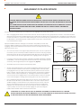
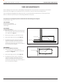
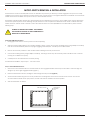
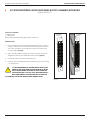
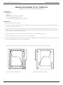
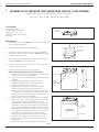
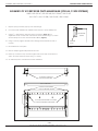
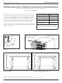
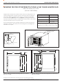
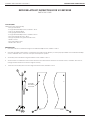
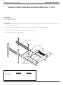
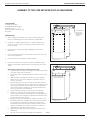
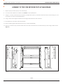
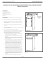
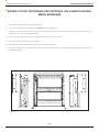
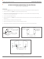
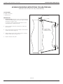
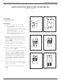
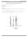
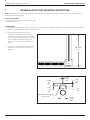
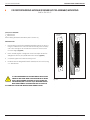
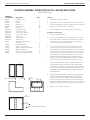
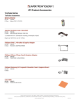
90 SERIES USER’S MANUAL
TABLE OF CONTENTS
SECTION 1 ENGAGEMENT OF ITA WITH RECEIVER
SECTION 2 CARE AND MAINTENANCE
SECTION 3 ASSEMBLY OF VXI RECEIVER ONTO MAINFRAME
SECTION 4 ASSEMBLY OF SHELF/HORIZONTAL MOUNTING FRAME TO RACK
SECTION 5 ASSEMBLY OF TWO TIER RECEIVER ONTO HP OR TEKTRONIX MAINFRAME
SECTION 6 ASSEMBLY/MOUNTING INSTRUCTIONS FOR CAST ADAPTER SHELL
SECTION 7 ASSEMBLY/INSTALLATION OF EDGE CARD ADAPTERS/L-SHAPED ENCLOSURE
SECTION 8 TROUBLE-SHOOTING AND SOLUTIONS
SECTION 9 PRECAUTIONARY NOTES
SECTION 10 CROSS-REFERENCE TABLES
Please note that any printed or downloaded User Manuals or Procedure Sheets may not reflect the most current
revisions. The information contained in these materials is subject to change.
For the most current information available, visit www.vpc.com.
1/6/15
VIRGINIA PANEL CORPORATION
90 SERIES USER’S MANUAL: SECTION 1
ENGAGEMENT OF ITA WITH RECEIVER
CAUTION: WHEN ENGAGING THE ITA WITH THE RECEIVER, CAUTION MUST BE TAKEN TO ENSURE THAT THE ITA
IS PARALLEL WITH THE RECEIVER UPON ENGAGEMENT AND THAT THE ITA ROLLERS ARE ENGAGED AT THE SAME
TIME!
ALL POWER SUPPLIES FOR THE SYSTEM SHOULD BE PROPERLY DISCONNECTED PRIOR TO HANDLING. CAUTION
SHOULD ALWAYS BE USED WHEN ENGAGING, MAKING SURE THAT ALL FOREIGN OBJECTS ARE REMOVED
FROM THE SYSTEM.
Listed below are the required steps to be taken prior to the engagment of the ITA and receiver.
•
Prior to engaging an ITA with the receiver for the first time, the user may find it to be good practice to check to see if all the modules
(ITA and receiver) have been installed properly. This would involve the inspection of the module ends - ensuring the even height of all
module ends relative to one-another. While checking this, the user should verify the positioning of the modules themselves. It is crucial
for all modules to be installed properly. Install modulues such that Pin 1 is located at the
top of the ITA/receiver frame.
Improper installation will cause damage to the modules, and possibly to the ITA and/
or receiver. All ITA modules have to match the receiver modules. This means that upon
engaging, an ITA module will mate with its respective receiver module (Power ITA to mate
with Power receiver, etc.).
•
•
TOP LATCH
To secure the receiver to the plug and play plates/rack system, the two top latches on
the receiver (one on each side) should be locked into the hooks on the plug and play
plate/rack system. The two top latches should be flush with the top of the receiver and
the two thumb screws should be tightened before engaging the ITA. See Figure A.
For VXI type receivers (Part # 310104127, 310104194, 310104248, 310104299, 310104307,
& 310104279) — the two securing screws located near the top of the receiver (one on
each side), must be tightened prior to ITA engagement (Figure B).
•
The handle may now be rotated to the lowered position.
•
The ITA, upon being inspected, is now ready for engagement with the receiver. The
receiver should be checked one last time for any foreign objects that may hinder
the engagement. The top rollers of the ITA may then be placed onto the receiver’s
built-in “hangers” with the handle in the lowered position. The ITA may be engaged
with the receiver only if properly lined up - meaning that the ITA must be placed
onto the receiver in the upright position. Care should be taken to have the top/side
notch of the ITA align for “mating” with the keying tab on the top of the receiver.
•
Due to additional equipment being added onto the ITA, the user may find that the
ITA and receiver will not line up as described above. One reason may be that the
additional weight on the ITA will cause it to pull away from the receiver at the top.
The user should apply pressure to the top of the ITA to counter the weight that is
pulling the top of the ITA away from the receiver (with the receiver handle in the
“open” position). The user may then carefully engage the system by raising the
handle until the handle makes contact with the receiver.
THUMB SCREW
HANGER
Figure A.
SECURING SCREW
Figure B.
IN THE EVENT OF COMPLICATIONS, SUCH AS IMPROPER ALIGNMENT OF MODULES OR THE ITA, A TRAINED
TECHNICIAN SHOULD BE NOTIFIED IMMEDIATELY TO AVOID ANY DAMAGE TO THE SYSTEM. THIS SHOULD ALSO APPLY
TO ANY DIFFICULTIES THAT MAY BE EXPERIENCED DURING ENGAGEMENT.
For the most current information available, visit www.vpc.com
1/6/15
VIRGINIA PANEL CORPORATION
90 SERIES USER’S MANUAL: SECTION 2
CARE AND MAINTENANCE
Serious damage can be caused due to mishandling or dropping the ITA or any system parts. The 90 Series and VXI Interface
System have been designed to be maintenance free, yet care does need to be taken when handling the ITA.
Upon receiving Interchangeable Test Adapters from VPC, it is recommended that ITA squareness is noted using the steps
below to verify future squareness (such as after being mishandled or dropped).
Procedure For Checking ITA Squareness When Unit Has Been Damaged or Dropped
(Use procedure 1 or 2)
PARTS REQUIRED
ITA Frame being checked
Precision Square (preferably 18”)
Feeler Gage
PROCEDURE 1
(using a Surface Plate) —
1. Place ITA onto a Surface Plate with the ITA Frame’s
top on the Surface Plate and contact side facing
you as illustrated in Figure A.
2.
Slide Precision Square up to left side (P1) of ITA.
3.
Place Feeler Gage at point A and B (Figure A).
4.
The difference between point A and point B
equals the squaring. This should be done upon
receipt of the ITA from the VPC factory and
recorded for referencing when the ITA is subject to
an out of squareness condition.
PRECISION SQUARE
POINT B
TOP OF ITA DOWN
POINT A
SURFACE PLATE
Figure A.
PROCEDURE 2
(for checking alignment in the field) —
1. Place the side of the Precision Square on the top left (P1) of the ITA with contact side
facing you as in Figure B.
2.
Place Feeler Gage at point C and D (Figure B).
3.
The difference between point C and point D
equals the squaring. This should be done upon
receipt of the ITA from the VPC factory and
recorded for referencing when the ITA is subject to
an out of squareness condition.
PRECISION SQUARE
POINT D
TOP OF ITA UP
POINT C
Figure B.
For the most current information available, visit www.vpc.com
1/6/15
VIRGINIA PANEL CORPORATION
90 SERIES USER’S MANUAL: SECTION 2
MICRO-SWITCH REMOVAL & INSTALLATION
A Microswitch is used in the 90 Series/VXI receivers to determine the presence (or absence) of an ITA engaged in the system. It is usually
configured so that power to the interface is turned off when there is no ITA present. An integrated Microswitch is standard on the 25 and 50
module receivers and available as an option for the 3, 6 and 10 Module receivers.
The 90 Series and VXI Interface Systems have been designed to be maintenance free; however, in the unlikely event that the Microswitch
needs to be replaced, please use the following VPC part numbers to order a replacement Microswitch: Part # 310 113 200 for 25 and 50
module receivers; and Part # 310 113 180 for 3, 6 and 10 module receivers. For removal/installation of the Microswitch, please read the
following steps.
AS WITH ALL ELECTRICAL SYSTEMS - DISCONNECT
ALL ELECTRICAL SUPPLIES TO THE SYSTEM PRIOR TO
REMOVAL OF MICROSWITCH.
For 25 and 50 Module Receivers:
1. Disengage the ITA from the receiver (remove the ITA completely).
2.
With the receiver handle still in the open position (handle is down), unscrew the two plate retaining screws (using a Phillips screwdriver)
that are located immediately below the top right engaging mechanism/slot - this will expose the Microswitch.
3.
Remove the necessary modules so that the Microswitch retaining screws may be accessed.
4.
Unscrew the retaining screws (using a Phillips screwdriver), removing each as they are loosened (caution should be used so that the
screw(s) do not fall into the system).
5.
Carefully remove the Microswitch for continuity testing.
For Microswitch installation, repeat steps 1 - 5 in reverse order.
For 3, 6 and 10 Module Receivers:
1. There are four slots machined into the receiver beside the two engagement slides that accept the ITA rollers. Locate the large slot
along the top of the right engagement slide (Figure 1).
2.
Place the Microswitch in the slot, feeding the wires through the hole provided (Figure A).
3.
Attach the Microswitch using the two screws provided. The mounting holes are located in the side of the receiver. One can be
accessed with the handle in the open position, and the other with the handle in the closed position.
4.
Wire the Microswitch as desired.
WIRE THROUGH-HOLE
Figure A.
MICROSWITCH
MOUNTING
SLOT
FIGURE 1. 10 MODULE RECEIVER
For the most current information available, visit www.vpc.com
1/6/15
VIRGINIA PANEL CORPORATION
90 SERIES USER’S MANUAL: SECTION 2
VXI DISCRETE WIRING MODULE RETAINER BLOCKS ASSEMBLY/MOUNTING
PART # 510 109 117
PARTS/TOOLS REQUIRED
1
/16 Allen Wrench
3
/32 Allen Wrench
Discrete Wiring Module Retainer Blocks (Part # 510 109 117)
RETAINER
BLOCK
RETAINER
BLOCK
1.
Insert module(s) into Discrete Wiring Retainer Blocks (Part # 510 109 117).
Using a 3/32 Allen Wrench, rotate the module mounting screws until they
start to become tight. If the module block cannot be rotated, loosen
the screws slightly (Figure A).
2.
Place assembly against a straight, flat surface and adjust the Discrete
Wiring Blocks until they are parallel with the flat surface (Figure B).
3.
Completely tighten the module mounting screws.
4.
Install the Discrete Wiring Retainer Block assembly into the receiver using
a 1/16 Allen Wrench.
FLAT SURFACE
INSTRUCTIONS
IT IS RECOMMENDED THAT DISCRETE WIRING BLOCKS ARE
LIMITED TO NO MORE THAN 5 PER SYSTEM WITH NO MORE
THAN 3 BLOCKS BEING ADJACENT TO EACH OTHER. THE
VXI RECEIVER (PART # 310 104 127) IS DESIGNED FOR USE
WITH INTERCONNECT ADAPTERS AND WILL NOT SUPPORT
A SYSTEM FULLY POPULATED WITH DISCRETE WIRING BLOCKS.
Figure A.
For the most current information available, visit www.vpc.com
Figure B.
1/6/15
VIRGINIA PANEL CORPORATION
90 SERIES USER’S MANUAL: SECTION 2
REMOVAL/REPLACEMENT OF 5/32” DOWEL PINS
PART # 310 104 176, 310 104 121 AND 310 104 135
PARTS REQUIRED
Part # 266553 includes:
• Primer T7471
• Loctite 271
• 0.820” Dimension Block (Part # 4227 82 000)
• Two 5/32” Dowel Pins (Part # 4227 00 119)
• 1/8” Drive Pin Punch (not included with Part # 266553)
INSTRUCTIONS
1.
Remove all modules from the receiver.
2.
Turn over the receiver so that the back side is showing. Place supports under the receiver’s front face such that the Dowel Pins may be
pushed past the face of the receiver.
3.
Using a 1/8” Drive Pin Punch, press out the Dowel Pins through the 0.128” diameter holes* (see drawing below). Turn receiver face up.
*NOTE: If there are no 0.128” diameter holes on the back side of the receiver, we recommend that the unit be sent back to Virginia Panel Corporation for the replacement of the pins.
4.
Spray T7471 primer onto one of the Dowel Pins, and cover the bottom 3/8” of the pin with Loctite 271.
5.
Start the Dowel Pin into the front hole of the receiver (see drawing below).
6.
Place the supplied 0.820” Dimension Block over the Dowel Pin and press the Dowel Pin until it is flush with the Dimension Block. Wipe off
any excess Loctite. Repeat steps 4 - 6 for the other Dowel Pin.
NOTE: 6 Module receiver is shown as an example only — Dowel Pin locations on other two receivers are similar
DOWEL PIN
INSERTION HOLES
DOWEL PIN
REMOVAL HOLES
Figure A. 6 Module Receiver (Front).
Figure B. 6 Module Receiver (Back).
For the most current information available, visit www.vpc.com
1/6/15
VIRGINIA PANEL CORPORATION
90 SERIES USER’S MANUAL: SECTION 3
ASSEMBLY OF VXI RECEIVER ONTO MAINFRAME (FOR ALL C-SIZE SYSTEMS)
PART # 310 113 147 / 310 113 148 / 310 113 149 / 310 113 167
310 113 171 / 310 113 198 / 310 113 247 / 310 113 249
TOOLS REQUIRED
#1 Phillips Screwdriver
#1 Straight Blade Screwdriver
Allen Wrenches: 1/16, 3/32, 1/8
Adapter Jigs (Part # 411 101 125)
Putty Knife
BOTTOM COVER PLATE
LOCKING
THUMB SCREW
RECEIVER
Figure A.
INSTRUCTIONS
1.
Place mainframe on back (Figure A). (Remove outer mainframe
shell on Tektronix Mainframe.)
2.
Remove standard flanges from VXI mainframe.
3.
Install the two adapter jigs (Part # 411 101 125) into mainframe
at positions 1 and 12 (note top of adapter (Figure B). Fasten with
the 2.5mm screws provided.
4.
Place receiver onto adapter jig pins, aligning pins with holes in
innerframe (Figure C). Latches will engage.
5.
6.
ALIGNMENT PINS
TOP
ADAPTER JIG
(2 REQUIRED)
Figure B.
Loosen locking thumb screws on both sides of receiver at latch
until latch can be depressed.
Secure and locate one flange at a time as follows:
After reading Liquid Steel Epoxy instructions thoroughly:
A. Dispense half of the two-part cartridge onto a clean surface
and mix until a uniform color is obtained.
B. Using a putty knife, completely fill all the clearance holes on
the flange.
C. Fill all threaded mounting screw locations on the
mainframe. (Make sure not to get epoxy inside the
mainframe. Wipe off excess if necessary).
D. Apply a thin layer of epoxy to the side of mainframe
opposite the inside area on flange. (If using an HP
Mainframe, remove plastic strip covering mounting screws,
then apply epoxy to both sides of the thin metal shim stock
supplied with the adapter kit. The shim is placed into the
recess on each side of the mainframe.)
E. Apply a thin layer of epoxy to the inside area of the flange.
F. Using the 1/8” Allen wrench and the stainless steel shoulder
screws, begin to install the VPC flanges onto the VXI
Mainframe. Place shoulder screw through the rotation block
and thread two turns into the side of the receiver. Engage
latch catches and tighten locking thumb screws. Press the
flange against the mainframe. Thread screws (with washers)
two turns into the mounting holes. With all mounting screws
threaded into holes two turns (and washers at head of
screws), apply epoxy liberally around screws and into the
clearance holes, filling any voids which may be present.
G. Tighten the mounting screws of the flange into the side of
the mainframe.
H. Wipe off any excess epoxy from flange and mainframe.
ROTATION BLOCK
ADAPTER JIG
FLANGE
MAINFRAME
THREADED
MOUNTING
HOLES
LATCH CATCH
Figure C.
C-SIZE VXI
MAINFRAME
FLANGE
MOUNTING
HOLES
BOTTOM
Figure D.
VXI001
Page 1 of 2
For the most current information available, visit www.vpc.com
1/6/15
VIRGINIA PANEL CORPORATION
90 SERIES USER’S MANUAL: SECTION 3
ASSEMBLY OF VXI RECEIVER ONTO MAINFRAME (FOR ALL C-SIZE SYSTEMS)
PART # 310 113 147 / 310 113 148 / 310 113 149 / 310 113 167
310 113 171 / 310 113 198 / 310 113 247 / 310 113 249
7.
Repeat epoxy procedure (step 6) to the other flange.
8.
Let receiver and mainframe sit undisturbed for 24 hours so epoxy will fully cure.
9.
Using a 1/16” Allen wrench, remove bottom cover plate. (Figure A) Turn
adjustment screws on each side at the bottom of the receiver using a 3/32” Allen
wrench until tip of set screw touches Rotation Block. (Figure E)
10.Using 1/8” hex key, tighten shoulder screws through rotation blocks into side of
receiver.
11. Re-install bottom cover plate.
ADJUSTMENT
SCREW
ROTATION
BLOCK
Figure E.
12. Remove adapter jigs and ship them back to VPC.
13. Place top cover bar on top of receiver with bevel to front and secure with four
4-40 x .75 socket head cap screws using 3/32” hex key.
14. On Tektronix systems, re-install outer shell of mainframe.
TO RELEASE, PRESS BOTH
LATCHES AT SAME TIME
TOP COVER PLATE
LOCKING THUMB SCREWS
LOCK THE RELEASE LATCHES
BOLTS SECURE RECEIVER TO FLANGES
AFTER VXI HAS BEEN CONFIGURED
Figure F.
VXI001
Page 2 of 2
For the most current information available, visit www.vpc.com
1/6/15
VIRGINIA PANEL CORPORATION
90 SERIES USER’S MANUAL: SECTION 3
MOUNTING SINGLE TIER VPC RECEIVER TO VXI PLUG & PLAY CHASSIS ADAPTER PLATE
PART # 310 113 248 / 310 113 257 / 310 113 272 / 310 113 350
(FOR ALL C-SIZE SYSTEMS)
Virginia Panel Corporation has developed four receiver mounting plates to be
used with VXI Plug & Play compliant chassis in accordance with the VXI Plug &
Play Systems Alliance specification VPP-8. There is a standard mounting plate
for the 8U VXI chassis (Figure C) and the 9U VXI chassis (Figure D), as well as a
special mounting plate for Racal Instruments 9U VXI chassis (frame dimensions
are the same as shown in Figure 2). The special plate for the Racal 9U chassis
includes a sheet metal trim plate that allows access to the power switch.
VXI Plug & Play Chassis
These mounting plates attach to flanges supplied by the chassis manufacturer*,
allowing the receiver to bolt directly on the mounting plate. Special alignment
hardware is not required.
3.960±.010
VPP8 FLANGE OFFSET
DIMENSIONAL REQUIREMENT
Used with Part #
Tektronix 1410
310 113 248
Agilent 1401B
310 113 248
Racal Instruments 1261B
310 113 272
Agilent 8400 Series
310 113 350
Can use 9U Mounting Plate (Part # 310 113 257)
with Tektronix and Agilent chassis if using a cable
tray.
VXI CHASSIS WITH PLUG AND
PLAY FLANGES INSTALLED
COVER PLATE AND MOUNTING HARDWARE
(SUPPLIED WITH PLUG AND PLAY PLATE,
ATTACHES TO VPC RECEIVER)
VXI INSTRUMENT
PLUG & PLAY FLANGES
Figure A.
[6.096]
.24
Figure B.
[6.35]
.25
[334.84]
13.97
[482.6]
19.00
[37.59]
1.48
#10-32 X .50 MOUNTING
HARDWARE (4 PCS)
[6.35]
[6.096]
VPC
PLUG AND
.25 PLAY PLATE
.24
[348.74]
13.73
Figure C. VXI Plug and Play Mounting Plate for 8U Chassis.
Part # 310 113 248.
[399.288]
15.72
[482.6]
19.00
[50.29]
1.98
[361.44]
14.23
[400.81]
15.48
Figure D. VXI Plug and Play Mounting Plate for 9U Chassis.
Part # 310 113 257 and 310 113 272.**
*Flanges must be ordered from the manufacturer when ordering the chassis.
** Part # 310 113 272 includes a special sheet metal trim plate allowing access to the power switch.
For the most current information available, visit www.vpc.com
1/6/15
VIRGINIA PANEL CORPORATION
90 SERIES USER’S MANUAL: SECTION 3
MOUNTING TWO TIER VPC RECEIVER TO VXI PLUG & PLAY CHASSIS ADAPTER PLATE
PART # 310 113 364 / 310 113 375
(FOR ALL C-SIZE SYSTEMS)
Virginia Panel Corporation has developed three receiver mounting plates to be
used with VXI Plug & Play compliant chassis in accordance with the VXI Plug &
Play Systems Alliance specification VPP-8. There is a standard mounting plate
for most VXI chassis (Figure A) and the 14U (Figure B), mounting plate for Racal
Instruments VXI chassis. The plate for the Racal 14U chassis includes a sheet metal
trim plate that allows access to the power switch.
These mounting plates attach to flanges supplied by the chassis manufacturer*,
allowing the receiver to bolt directly on the mounting plate. Special alignment
hardware is not required.
VXI Plug & Play Chassis
Used with Part #
Tektronix 1410
310 113 375
Agilent1401 & 8400 Series
310 113 375
Racal Instruments 1261B
310 113 364
Can use 9U Mounting Plate (Part # 310 113 257)
with Tektronix and Agilent chassis if using a cable
tray.
VXI CHASSIS WITH PLUG
AND PLAY FLANGES
INSTALLED
3.960±.010
VPP8 FLANGE OFFSET
DIMENSIONAL REQUIREMENT
VXI INSTRUMENT
PLUG & PLAY FLANGES
Figure A.
#10-32 X .50 MOUNTING
HARDWARE (4 PCS)
Figure B.
1.98
[50.29]
1.98 TIER
TWO
[50.29]
PLUG AND PLAY PLATE
19.00
[482.60]
19.00 TO RECEIVER
LANYARDS ATTACH
[482.60]
USING SUPPLIED
HARDWARE
12.25
[311.15]
17.50
[444.50]
17.50
[444.50]
22.72
[577.09]
20.50
[520.70]
20.50
[520.70]
24.47
[621.54]
Figure C. VXI Plug and Play Mounting Plate for 14 Chassis.
Part # 310 113 364.
Figure D. VXI Plug and Play Mounting Plate for 14U Chassis.
Part # 310 113 375.
*Flanges must be ordered from the manufacturer when ordering the chassis.
For the most current information available, visit www.vpc.com
1/6/15
VIRGINIA PANEL CORPORATION
90 SERIES USER’S MANUAL: SECTION 3
RECEIVER LATCH KIT INSTRUCTIONS FOR VXI RECEIVER
PART # 310 113 295
TOOLS REQUIRED
VXI Receiver (Part # 310 104 248)
• Two (2) Latch Blocks
• Four (4) Flathead Phillips Screws, 4-40UNC x .38 LG.
• One (1) Left Rotation Block
• One (1) Right Rotation Block
• Four (4) Flathead Phillips Screws, 10-32UNF x .50 LG.
• Two (2) Dowel Pins HST .187 x .38 LG.
• Two (2) Lanyards8. Four (4) Buttonhead screws,
• 32UNC x .50 LG.
• Two (2) Shoulder Screws,
• 24UNC .250 x .375 LG.
INSTRUCTIONS
1.
Mount latch blocks to mainframe using the four flathead Phillips Screws, 4-40UNC x .38 LG.
2.
Mount left and right rotation blocks. Counterbores for shoulder screws will face put when properly installed. Insert four flathead Phillips
screws, 10-32UNF x .50 LG., from rear, then press dowel pins into position.
3.
Attach lanyard to mainframe using buttonhead screws, 8-32UNC x .50 LG.
4.
Attach receiver to mainframe. Place receiver between the rotation blocks and insert two shoulder screws, 10-24UNC .250 x .375 LG.,
through rotation blocks into the receiver. Tighten securely.
5.
Attach free end of lanyard to receiver using buttonhead screws, 8-32UNC x .50 LG.
LANYARD
MOUNTING
LOCATION
LEFT
RIGHT
For the most current information available, visit www.vpc.com
1/6/15
VIRGINIA PANEL CORPORATION
90 SERIES USER’S MANUAL: SECTION 4
ASSEMBLY OF SHELF/HORIZONTAL MOUNTING FRAME ONTO 19” RACK
TOOLS REQUIRED
Part # 310 104 200 or 310 104 232
#1 Phillips Head Screwdriver
INSTRUCTIONS
1.
Attach the Top Mounting Bracket to the framework of the rack with the supplied hardware. This is best done from behind the rack, with
the Top Adapter Panel in place.
2.
Slide Top Support Bar through slots in Top Adapter Panel and into the grooves of the Top Mounting Bracket.
3.
Tighten Top Mounting Bracket and Top Adapter Panel screws firmly into place.
4.
Attach the Top Support Bar to the Shelf Frame.
TOP MOUNTING BRACKET
TOP ADAPTER PANEL
B
A
[87.376]
3.44
[88.9]
3.5
[484.12]
19.06
TOP BAR SUPPORT
NOTE:
Dimension for A
Dimension for B
310 104 200
[268.22] 10.56”
[381] 15.00”
310 104 232
[469.9] 18.50”
[485.648] 19.12”
For the most current information available, visit www.vpc.com
1/6/15
VIRGINIA PANEL CORPORATION
90 SERIES USER’S MANUAL: SECTION 5
ASSEMBLY OF TWO-TIER RECEIVER ONTO HP MAINFRAME
TOOLS REQUIRED
#1 Phillips Screwdriver
#1 Straight Blade Screwdriver
Allen Wrenches: 1/16, 3/32, 1/8
Adapter Jigs (Part # 411 101 125)
Putty Knife
SUPPORT HERE TO
KEEP FACE OF
RECEIVER LEVEL
WITH FACE OF
CHASSIS
INSTRUCTIONS
1.
Place mainframe on its back side so that the opening faces up.
Remove standard flanges from VXI mainframe (if applicable).
2.
Install the two adapter jigs (Part # 411 101 125) into mainframe at
positions 1 and 12 (note top of adapter). Fasten with the 2.5 mm
screws provided.
3.
Place receiver onto adapter jig pins, aligning pins with holes in
innerframe.
4.
Loosen locking thumb screws on both sides of receiver at latch until
latch can be depressed.
5.
Secure and locate one flange at a time as follows:
6.
Please note that the use of epoxy is essential to maintain receiver
alignment, especially in situations where mounting holes are oval in
shape.
After reading Liquid Steel Epoxy instructions thoroughly:
A. Dispense half of the two-part cartridge onto a clean surface and
mix until a uniform color is obtained.
B. Using a putty knife, completely fill all the clearance holes on the
flange.
SHIM TO GO BETWEEN
C. Fill all threaded mounting screw locations on the mainframe.
FLANGE AND CHASSIS
(Make sure not to get epoxy inside the mainframe. Wipe off
excess if necessary.)
D. Apply a thin layer of epoxy to the side of mainframe opposite
the bare area on flange. Remove plastic strip covering mounting
screws, then apply epoxy to both sides of the thin metal shim
stock supplied with the adapter kit. The shim is placed into the
recess on each side of the mainframe.
E. Apply a thin layer of epoxy to the bare area of the flange.
F. Using the 1/8” Allen wrench and the stainless steel shoulder
screws, begin to install the VPC flanges onto the VXI Mainframe.
Place shoulder screw through the rotation block and thread two
turns into the side of the receiver.
G. Engage latch catches and tighten locking thumb screws. Press
the flange against the mainframe. Thread screws (with washers)
two turns into the mounting holes. With all mounting screws
Figure B.
threaded into holes two turns (and washers at head of screws),
apply epoxy liberally around screws and into the clearance
holes, filling any voids which may be present.
H. Tighten the mounting screws of the flange into the side of the
mainframe.
I. Wipe off any excess epoxy from flange and mainframe.
VXI003
Page 1 of 2
Figure A.
For the most current information available, visit www.vpc.com
1/6/15
VIRGINIA PANEL CORPORATION
90 SERIES USER’S MANUAL: SECTION 5
ASSEMBLY OF TWO-TIER RECEIVER ONTO HP MAINFRAME
7.
Repeat epoxy procedure (step 6) to the other flange.
8.
Let receiver and mainframe sit undisturbed for 24 hours so epoxy will fully cure.
9.
Using a 1/16” hex key, remove bottom cover plate. Turn adjustment screws on each side at the bottom of the receiver using a 3/32” hex
key until tip of set screw touches Rotation Block.
10.Using 1/8” Allen wrench, tighten shoulder screws through rotation blocks into side of receiver.
11. Re-install bottom cover plate and attach lanyards.
12. Remove adapter jigs and ship them back to VPC. (For refund if applicable)
13. Place top cover bar on top of receiver with bevel to front and secure with 4-40 x .75 socket head cap screws using 3/32 Allen wrench
(Figure C).
VIEW OF LEFT SIDE
VIEW OF RIGHT SIDE
Figure C.
VXI003
Page 2 of 2
For the most current information available, visit www.vpc.com
1/6/15
VIRGINIA PANEL CORPORATION
90 SERIES USER’S MANUAL: SECTION 5
ASSEMBLY OF TWO-TIER RECEIVER ONTO TEKTRONIX 1410 & HEWLETT-PACKARD
E8400A MAINFRAME
TOOLS REQUIRED
#1 Phillips Screwdriver
#1 Straight Blade Screwdriver
Allen Wrenches: 1/16, 3/32, 1/8
Adapter Jigs (Part # 411 101 125)
Putty Knife
SUPPORT HERE TO
KEEP FACE OF
RECEIVER LEVEL
WITH FACE OF
CHASSIS
INSTRUCTIONS
1.
Place mainframe on its back side so that the opening faces up.
2.
Remove standard flanges from VXI mainframe (if applicable).
3.
Install the two adapter jigs (Part # 411 101 125) into mainframe at
positions 1 and 12 (note top of Adapter). Fasten with the 2.5 mm
screws provided.
4.
Place receiver onto adapter jig pins, aligning pins with holes in
innerframe.
5.
Loosen locking thumb screws on both sides of receiver at latch until
latch can be depressed.
6.
Secure and locate one flange at a time as follows:
NOTE: The use of epoxy is essential to maintain receiver alignment,
especially in situations where mounting holes are oval in shape.
After reading Liquid Steel Epoxy instructions thoroughly:
A. Dispense half of the two-part cartridge onto a clean surface
and mix until a uniform color is obtained.
B. Using a putty knife, completely fill all the clearance holes on
the flange.
C. Fill all threaded mounting screw locations on the mainframe.
(Make sure not to get epoxy inside the mainframe. Wipe off
excess if necessary.)
D. Apply a thin layer of epoxy to the side of mainframe opposite
the bare area on flange. Remove plastic strip covering
mounting screws, then apply epoxy to both sides of the thin
metal shim stock supplied with the adapter kit. The shim is
placed into the recess on each side of the mainframe.
E. Apply a thin layer of epoxy to the bare area of the flange.
F. Using the 1/8” Allen wrench and the stainless steel shoulder
screws, begin to install the VPC flanges onto the VXI
Mainframe. Place shoulder screw through the rotation block
and thread two turns into the side of the receiver.
G. Engage latch catches and tighten locking thumb screws.
Press the flange against the mainframe. Thread screws (with
washers) two turns into the mounting holes. With all mounting
screws threaded into holes two turns (and washers at head
of screws), apply epoxy liberally around screws and into the
clearance holes, filling any voids which may be present.
H. Tighten the mounting screws of the flange into the side of the
mainframe.
I. Wipe off any excess epoxy from flange and mainframe.
Figure A.
SHIM TO GO BETWEEN
FLANGE AND CHASSIS
Figure B.
VXI004
Page 1 of 2
For the most current information available, visit www.vpc.com
1/6/15
VIRGINIA PANEL CORPORATION
90 SERIES USER’S MANUAL: SECTION 5
ASSEMBLY OF TWO-TIER RECEIVER ONTO TEKTRONIX 1410 & HEWLETT-PACKARD
E8400A MAINFRAME
7.
Repeat Epoxy procedure (step 6) to the other Flange.
8.
Let receiver and mainframe sit undisturbed for 24 hours so epoxy will fully cure.
9.
Using a 1/16” hex key, remove bottom cover plate. Turn adjustment screws on each side at the bottom of the receiver using a 3/32” hex
key until tip of set screw touches Rotation Block.
10.Using 1/8” hex key, tighten shoulder screws through rotation blocks into side of receiver.
11. Re-install bottom cover plate and attach lanyards.
12. Remove adapter jigs and ship them back to VPC. (For refund if applicable)
13. Place top cover bar on top of receiver with bevel to front and secure with 4-40 x .75 socket head cap screws using 3/32” Allen Wrench
(see illustration below).
VIEW OF LEFT SIDE
VIEW OF RIGHT SIDE
Figure C.
VXI004
Page 2 of 2
For the most current information available, visit www.vpc.com
1/6/15
VIRGINIA PANEL CORPORATION
90 SERIES USER’S MANUAL: SECTION 6
ASSEMBLY/MOUNTING INSTRUCTIONS FOR ADAPTER SHELL
PART # 510 109 179 (T-BAR DESIGN)
TOOLS REQUIRED
#1 Straight blade screwdriver
#1 Phillips screwdriver
VXI CARD
2.
4.
Apply locktite to threads of retaining studs and thread nut
onto stud (See Figure D), keeping the Retaining Stud parallel*
with the edge of the card torque to 4 in-lb [.45 Nm] maximum.
Repeat for other end of card.
NOTE: Mounting bar must be parallel to the edge of the card.
Incorrect alignment may cause the receiver to close improperly
(Figure E).
[255.78]
10.07
SAVE
[30.23]
1.19
REF.
Figure A.
If plastic cups or metal inserts are present, remove and save two captive screws from VXI Card (Figure A). If VXI Card does
not have two non-threaded holes top and bottom of at least
.106” [2.69] dia. at the locations shown, (Figure B), punch using
VPC tool Part # 910 121 137, or drill per the instructions found on
the next page. When all required holes are present, proceed to
step 3.
NOTE: When drilling holes, take precautions to prevent metal
flakes from contaminating VXI card.
Place retaining studs through VXI Card and into Interconnect
adapter (See Figure C).
5.
TOP
REMOVE
PLASTIC
CLIP
FRONT
If card has a keying plate, it must be removed.
A.For Hewlett-Packard cards with type “Lexus”
metal extractors:
1. Remove top and bottom terminal block guides using
a number T10 Torx driver. Re-install screws to hold front
plate in place.
2. Remove top and bottom “Lexus” metal extractors using
a number T8 Torx driver. Re-install screws to hold side
panel in place.
3.
[5.08]
.20
TYP
DISCARD
INSTRUCTIONS
1.
[12.45]
.49
TYP
[3.05]
.12
Figure B.
INTERCONNECT
ADAPTER
CAPTIVE
SCREW
NUT
LOCTITE
VXI CARD
RETAINING
STUD
Figure D.
Figure C.
SLOT IN
MAINFRAME
MOUNTING
BAR
Replace captive screw through VXI Card and through retaining
stud. (Figure F) Repeat for other end of card.
[135.89]
5.35
BACK
FACE
OF VXI
CARD
Figure E.
Figure F.
VMV1300
For the most current information available, visit www.vpc.com
1/6/15
VIRGINIA PANEL CORPORATION
90 SERIES USER’S MANUAL: SECTION 6
ASSEMBLY/MOUNTING INSTRUCTIONS FOR ADAPTER SHELL
PART # 510 109 179 (T-BAR DESIGN)
INSTRUCTIONS
1.
Open punch (Figure A) by lifting movable handle; hold the VXI card with front panel (writing faces readable) facing operator.
2.
Place the panel into the “U” (Figure B) on the right hand side (marked bottom side).
3.
With the bottom of the panel pressed firmly against the back edge of “U”, move the handle down, punching the hole through
the panel. Do not punch through tapped hole.
4.
Turn the card over (with writing side down).
5.
Place the panel into the “U” (Figure B) on left hand side (marked top side) with the bottom of the panel pressed firmly against the back
edge of the “U’.
6.
Move the handle down, punching the hole through the panel.
7.
Replace the mounting screws. The card is now ready for mounting to the adapter.
8.
After punching several cards, the plug in the bottom of the punch will have to be removed to empty aluminum plugs.
AGAINST THIS EDGE
FOR TOP OF CARD
OR TO PUNCH TO THE
RIGHT OF THE EXISTING
HOLE
TOP SIDE
BOTTOM SIDE
AGAINST THIS EDGE
FOR BOTTOM OF
CARD OR TO PUNCH
TO THE LEFT OF THE
EXISTING HOLE
TOP OF TOOL
Figure B.
Figure A.
[3.048]
.12
[5.08]
.20
EXISTING CARD
MOUNTING HOLE
DRILL [2.69] .106 DIA
OR PUNCH [3.175] .125 DIA
Figure C.
VMV1300
For the most current information available, visit www.vpc.com
1/6/15
VIRGINIA PANEL CORPORATION
90 SERIES USER’S MANUAL: SECTION 6
ASSEMBLY/MOUNTING INSTRUCTIONS FOR ADAPTER SHELL
PART # 510 109 179 & 510 109 118 (CLAMP DESIGN)
TOOLS REQUIRED
#1 Phillips screwdriver
1
/16 Allen Wrench
CARD EJECTOR
INSTRUCTIONS
1.
CLAMP
Hewlett-Packard cards with “Lexus” type metal extractors
must use the T-Bar Design to attach the adapter shell (see
instructions on pages 17-18).
For all other cards, including HP cards without “Lexus”
metal extractors, continue on to #2.
2.
Remove adapter side plate and place on table with
open side up.
3.
Place VXI card ejectors between clamps and outside of
adapter (as shown in Figure A).
4.
Tighten clamp screws using 1/16 Allen Wrench, ensuring
adapter is flush with top and bottom.
5.
Replace adapter side plate.
TIGHTEN SCREW
USING 1/16” ALLEN
WRENCH TYP 2 PLCS
Figure A.
VMV1301
For the most current information available, visit www.vpc.com
1/6/15
VIRGINIA PANEL CORPORATION
90 SERIES USER’S MANUAL: SECTION 6
ASSEMBLY/MOUNTING INSTRUCTIONS FOR ADAPTER SHELL
PART # 510 109 118
[3.3] .13 DIA.
THRU, TYP.
8 PLCS.
TOOLS REQUIRED:
#1 Straight Blade Screwdriver
#1 Phillips Head Screwdriver
VXI CARD
[60.07]
2.39
PUNCH HOLE IF
NOT PRESENT
DISCARD
INSTRUCTIONS
1.
2.
If card has a keying plate, it must be removed.
A. For Hewlett-Packard cards with type “Lexus”
metal extractors:
1. Remove top and bottom terminal block guides
using a number T10 Torx driver. Re-install screws to
hold front plate in place.
2. Remove top and bottom “Lexus” metal
extractors using a number T8 Torx driver. Re-install
screws to hold side panel in place.
If plastic clips or metal inserts are present, remove
(Figure A). Also remove the 2.5 mm captive screws.
If the VXI card does not have 4 holes on each end
as shown in Figure B, drill mounting holes at locations
shown (.125” dia.).
NOTE: When drilling holes, take precautions to
prevent metal flakes from contaminating VXI card.
If all holes are present, proceed to Step 3.
3.
Place the 4 retaining studs through VXI card and into
Interconnect Adapter (Figure C).
4.
Apply Loctite to threads of retaining studs and thread
retaining nut onto the stud (Figure D), keeping the
retaining stud parallel with the edge of the card.
Torque to 4 in. lb. max. Repeat for all 4 locations.
NOTE: Retaining stud must be parallel to the edge
of the card. Incorrect alignment will prevent the
card from seating completely and will not allow the
receiver to close.
5.
6.
Insert new captive screws (18mm length) through the
VXI card, thread through the retaining stud (Figure E).
Repeat for all four locations.
[255.78]
10.07
REMOVE
PLASTIC
CLIP
SAVE
[12.446]
.49
TYP
[30.48]
1.20
TYP
[5.08]
.20
TYP
Figure B.
Figure A.
ADAPTER STUD
(4 PCS.)
RETAINING NUT
(4 PLCS)
VXI
CARD
Figure C.
Figure D.
RETAINING SCREW
(4 PLCS.)
Completed assembly should appear as shown in
Figure F.
Figure E.
[3.098]
.122
For the most current information available, visit www.vpc.com
Figure F.
1/6/15
VIRGINIA PANEL CORPORATION
90 SERIES USER’S MANUAL: SECTION 7
VERSAMOUNT EDGE CARD MOUNTING INSTRUCTIONS
NOTE:
The Versamount Edge Card Adapter features snap-in Unitrack card guides.
PARTS/TOOLS REQUIRED
Versamount Edge Card Adapter Kit (Part # 111 107 140)
Phillips screwdriver
INSTRUCTIONS
1.
To mount the brackets to an enclosure, drill two holes for each bracket, one for the antirotation pin and the other for a #4 or #6
machine screw, see dimensions below.
2.
Assemble the ADJUST-A-LOCK, using the hardware furnished, to the Versamount with the snap-in card guide in place.
3.
Slide the p.c. card and seat it in its connector. Lower the ADJUST-A-LOCK units onto the pc card and lock in position by tightening the
screws. (Locks p.c. card [227.33 mm] 8.95” maximum length)
4.
Remove the card by springing back the card locking member/s, or by loosening the screws. Slide out the p.c. card.
ADJUST-A-LOCK
#4 OR #6 SCREW
[140]
5.512
PC CARD GUIDE SLOT
[2.286]
.09
ANTI-ROTATION PIN
[3.3]
.13
[1.52]
.06
[3.3]
.13
[19.05]
.75
[10.16]
.40
[3.25] .128 DIA THRU
COUNTERBORE
[4.775] .188 DIA x DP.
TYP.
[18.786]
.74
Figure A.
For the most current information available, visit www.vpc.com
1/6/15
VIRGINIA PANEL CORPORATION
90 SERIES USER’S MANUAL: SECTION 7
UNIVERSAL EDGE CARD MOUNTING INSTRUCTIONS
NOTE: The Universal Edge Card Adapter features a Support Block that is tapped allowing for two screws to attach to the Support Block
from under the mounting surface.
PARTS/TOOLS REQUIRED
Universal Edge Card Adapter Kit (Part # 111 107 138)
#1 Phillips screwdriver
INSTRUCTIONS
1.
Using the dimensions provided below, calculate the distance that the card guides will need to be apart and the location of the holes
that will need to be drilled to attach the Support Blocks.
2.
Determine optimum placement of the
card guides, making sure that there are no
obstructions that may prevent the card guides
from folding for storage (the Edge Card Adapter
will permit itself to be folded by pulling the
release pin found on the side of the Support
Block).
3.
Cut surface at desired location to allow for the
installation of the card edge connector (not
supplied).
[181.356]
7.14
Figure A.
[14.986]
.59
REF
[2.03]
.08
REF
[3.3]
.13
REF
[5.59]
.22
REF
.190-32 UNF - 2B x .35 DP
TYP. 2 PLCS.
[17]
.67
[31.75]
1.25
REF
Figure B.
For the most current information available, visit www.vpc.com
1/6/15
VIRGINIA PANEL CORPORATION
VXI PROCEDURE SHEET
VXI DISCRETE WIRING MODULE RETAINER BLOCKS ASSEMBLY/MOUNTING
PART # 510 109 117
PARTS/TOOLS REQUIRED
1
/16 Allen Wrench
3
/32 Allen Wrench
Discrete Wiring Module Retainer Blocks (Part # 510 109 117)
RETAINER
BLOCK
RETAINER
BLOCK
1.
Insert module(s) into Discrete Wiring Retainer Blocks (Part # 510 109 117).
Using a 3/32 Allen Wrench, rotate the module mounting screws until they
start to become tight. If the module block cannot be rotated, loosen
the screws slightly (Figure A).
2.
Place assembly against a straight, flat surface and adjust the Discrete
Wiring Blocks until they are parallel with the flat surface (Figure B).
3.
Completely tighten the module mounting screws.
4.
Install the Discrete Wiring Retainer Block assembly into the receiver using
a 1/16 Allen Wrench.
IT IS RECOMMENDED THAT DISCRETE WIRING BLOCKS ARE
LIMITED TO NO MORE THAN 5 PER SYSTEM WITH NO MORE
THAN 3 BLOCKS BEING ADJACENT TO EACH OTHER. THE
VXI RECEIVER (PART # 310 104 127) IS DESIGNED FOR USE
WITH INTERCONNECT ADAPTERS AND WILL NOT SUPPORT
A SYSTEM FULLY POPULATED WITH DISCRETE WIRING BLOCKS.
FLAT SURFACE
INSTRUCTIONS
Figure A.
For the most current information available, visit www.vpc.com
Figure B.
1/6/15
VIRGINIA PANEL CORPORATION
90 SERIES USER’S MANUAL: SECTION 8
PAINTING/ASSEMBLY INSTRUCTIONS FOR L-SHAPED ENCLOSURE
PART # 410 112 439
PARTS LIST
Part Number
DescriptionQty.
000225
254597
254596
269440
254237
269511
439702101
439702102
438600103
439702103
439702104
438600107
439702105
259268
267509
690401
691052
899997
902503
908400
PART # 410 112 450 ONLY
Adhesive, (4 oz.)
Handle
Ferrule
Rubber Foot
Grommet, Dzus
Stud, Dzus
Housing Assembly
Access Panel, Top
Access Panel, Bottom
Access Panel, Front
Gasket, Top
Gasket, Bottom
Gasket, Front
Screw, PH PHL, 6-32 X .625,
MS51957-31
Nut, MS21044C06
Washer, Flat, 10/32, SST
Washer, #6 Flat, MS15795-805
Washer, Lk Split, #10
Screw, SH CP, 8-32 X .312, Blk
Screw, PH PL, 10-32 X .500, SST
[6.35]
.25 R. TYP
[6.35]
.25 R. TYP
1
2
4
4
58
58
1
1
1
1
1
1
1
4
8
4
4
4
10
4
Painting:
1. Modify cover plates as needed.
2.
Using tape or another masking material, cover the areas on
the enclosure not to be painted as indicated by the drawing
below to ensure panel-frame conduction.
3.
Paint Housing and Cover plates (Exterior surfaces only).
Hardware and Gasketing:
4. Remove masking material.
5.
To mount each handle to the cover plates, seat each end
into a guide ferrule, then attach the handle to the outside
face of the cover using two 10-32 x 3/8 mounting screws,
two lock washers, and two flat washers.
6.
Insert one 1/4-turn fastener at a time through the front of
a cover plate. Lay cover plate face-down with 1/4-turn
fastener sticking up. Slide retaining washer over the fastener
such that the outer area of the washer is furthest away from
the cover plate (like a soup-bowl with a hole in the middle
of it). Slide a tube (.375 dia. with .220 inside dia.) over the
retaining washer and strike firmly with a mallet with cover
plate on a solid surface. Ensure that the fastener is retained
by washer. Repeat for all fasteners on each cover plate.
7.
Working on a flat surface, apply a thin layer of adhesive to a single gasket. Smooth with a putty knife or razor blade
so that there is a very thin, even layer (.003 - .005, or paper
thickness) on the gasket. Make sure the adhesive covers out
to all edges. (Avoid allowing build-up of excess adhesive in
the gasket holes).
8.
Immediately affix the gasket to the housing, first aligning the
inside of the gasket with the inside edge of the enclosure
opening. Check for proper alignment of the gasket and
housing holes and adjust as necessary. Once all holes are
aligned, immediately attach the cover plate and lock down
for at least 20 minutes to allow the adhesive to properly set.
9.
Repeat steps 7 & 8 for each cover.
[19.05]
.75 R. TYP
[6.35]
.25 R. TYP
[19.05]
.75 R. TYP
MASKED SHADED AREAS BEFORE PAINTING.
For the most current information available, visit www.vpc.com
1/6/15
VIRGINIA PANEL CORPORATION
90 SERIES USER’S MANUAL: SECTION 9
TROUBLESHOOTING
ITA Engagement Bearings/Studs are not lining up with the Engagement Slots of the receiver
• Check the alignment of the ITA Frame. There is a possibility that the ITA Frame will have misaligned itself if it is dropped (See Procedure
for Checking ITA Squareness on page 4, Section 3). Contact Virginia Panel Corporation - user adjustments to System, unless authorized,
will void the warranty.
• Forceful engagement of the receiver and the ITA will result in serious damage to multiple parts of the system (modules, receiver, ITA
and Contacts)!
ITA Frame is not lined up when in the process of engagement with the receiver
• With a typical contact load, approximately 35lbs force is needed to engage the handle. Consult with a VPC application engineer for
detailed contact loading information.
• If excessive force is required, this may indicate that the ITA out of alignment or that a Module is not mating with its intended Module.
Remove and inspect the ITA for alignment (See Procedure for Checking ITA Squareness on page 4, Section 3). Contact Virginia Panel
Corporation - user adjustments to System, unless authorized, will void the warranty.
• Check for foreign objects/tools.
• Verify the orientation of the receiver and ITA modules (See Section 2).
• Inspect the matching of modules - Power ITA Module to mate with Power receiver Module, etc. (See Section 2).
• Forceful engagement of the receiver and the ITA will result in serious damage to multiple parts of the system (modules,
receiver, ITA and Contacts)!
Excessive force is needed upon engaging the Handle
• This may indicate that the ITA was dropped and is out of alignment or that a Module is not mating with its intended Module. Remove
and inspect the ITA for alignment (See Procedure for Checking ITA Squareness on page 4, Section 3). Contact Virginia Panel
Corporation - user adjustments to system, unless authorized, will void the warranty.
• Check for foreign objects/tools.
• A damaged Contact(s) may provide enough resistance to notice. Upon replacing a Contact on the ITA, the mating Contact on the
receiver side should also be inspected and replaced if necessary (See Section 2).
• Verify the orientation of the receiver and ITA modules (See Section 2).
• Inspect the matching modules - Power ITA Module to mate with Power receiver Module, etc. (See Section 2).
• Forceful engagement of the receiver and the ITA will result in serious damage to multiple parts of the system (modules, receiver, ITA
and Contacts)!
ITA will not engage with the receiver after diagnosing the above problems
• Contact Virginia Panel Corporation - user adjustments to the System, unless authorized, will void the warranty.
No continuity upon engagement
• Upon replacing a Contact on the ITA, the mating Contact on the receiver side should also be inspected and replace if necessary (See
Section 2).
• Check wiring - replace if necessary.
• Contact not secured in module.
• 50 OHM ITA contact engaged with 95 OHM receiver contact will damage the 95 OHM contact.
• 95 OHM ITA contact engaged with 50 OHM receiver contact will not make continuity/contact.
A “short” in the wiring upon engagement
• A damaged Contact(s) may provide enough resistance to notice. Upon replacing a Contact on the ITA, the mating Contact on the
receiver side should also be inspected and replaced if necessary (See Section 2).
• Check wiring - replace if necessary.
receiver and ITA will not disengage
• This may indicate that the Engagement Mechanism within the receiver is faulty - contact Virginia Panel Corporation immediately-user
adjustments to System, unless authorized, will void the warranty.
For the most current information available, visit www.vpc.com
1/6/15
VIRGINIA PANEL CORPORATION
90 SERIES USER’S MANUAL: SECTION 10
PRECAUTIONARY NOTES
The following is a listing of precautionary notes found within this Manual and otherwise. They should be noted and followed for the
equipment to operate at an optimum state.
•
Never probe a contact without using a mating patchcord as a test lead.
•
Never forcefully engage a system if there is an excessive amount of resistance on the handle.
•
Never allow an ITA to drop as this may cause misaligned engagement and/or irreparable damage.
•
Always insert and extract a contact insertion/extraction tool inline with the contact. Never apply pressure to the side as this may break
either contact or tool. This also applies to forming and enlarging tools.
•
When engaging the ITA with the receiver, caution must be taken to ensure that the ITA is parallel with the receiver upon engagement
and that the ITA rollers are engaged at the same time!
•
It is advisable that power to the Interface System be disconnected prior to handling and maintenance.
•
Caution should always be used when engaging, making sure that all foreign objects are removed from the system.
•
50 OHM ITA contact engaged with 95 OHM receiver contact will damage the 95 OHM contact.
•
Use care when hinging receiver down. Always maintain hand contact to prevent receiver from dropping suddenly, resulting in
damage to the system.
For the most current information available, visit www.vpc.com
1/6/15