1
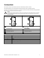
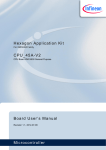
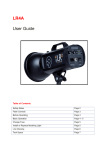
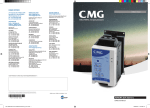
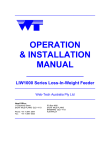
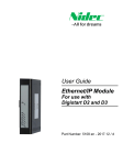
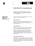
Profibus Module Instructions Important User Information Observe all necessary safety precautions when controlling the soft starter remotely. Alert personnel that machinery may start without warning. It is the installer's responsibility to follow all instructions in this manual and to follow correct electrical practice. The information contained in this manual is subject to change at any time and without prior notice. In no event will responsibility or liability be accepted for direct, indirect or consequential damages resulting from the use or application of this equipment. Installation Install the Profibus Module using the following procedure: CAUTION Remove mains and control voltage from the soft starter before attaching or removing accessories. Failure to do so may damage the equipment. 1. 2. 3. 4. 5. Remove control power and mains supply from the soft starter. Attach the module to the soft starter as illustrated. Set the module address to match the address set in the Master configuration tool. Apply control power to the soft starter. Insert the network connector and power up the module. To install the Profibus Module on the Aurora LPRB or Aurora LPRA: 1. Line up the module with the comms port slot. 2. Press the top retaining clip of the module into the soft starter chassis. 3. Press in the bottom retaining clip. CMG Aurora | Profibus Module 1106 (edition 1.0.0) 05551.C Aurora LPRA 08473.C Aurora LPRB 1 03550.A Remove the module using the following procedure: 1. Remove power from the module. 2. Remove control power and mains supply from the soft starter. 3. Disconnect all field wiring from the module. 4. Push a small flat-bladed screwdriver into the slots at the top and bottom of the module and depress the retaining clips. 5. Pull the module away from the soft starter. Configuration Import the latest .gsd file into your Master configuration tool. This file is available on the website www.cmggroup.com.au/Products/Drives/LPRA and www.cmggroup.com.au/Products/Drives/LPRB. If your Master uses on-screen icons, two graphic bitmap files are available from the CD or can be downloaded from the website. SSPM_N.bmp indicates normal mode. SSPM_D.bmp indicates diagnostic mode. NOTE The Profibus Module has a slave address range of 0 to 99. If the Profibus network fails, the module will leave data exchange mode after the network watchdog timeout period has expired. This timeout period is set at the Master configuration tool. A Communication Timeout parameter in the GSD file sets how soon after this event the soft starter will be forced into a trip state. The user can adjust the Communication Timeout parameter in the GSD file to any setting between 0 and 100 seconds. The default setting is 10 seconds. NOTE If the Communication Timeout parameter is set to 0, the current state of the soft starter will remain unchanged on a network failure. This gives the user the option of operating the soft starter via local control, but is NOT failsafe. Adjustment Before powering up the Profibus Module, set the two rotary switches so that the module address matches the address set in your Master configuration tool (the diagram shows the factory default setting for the rotary switches). ADDRESS MSD The module automatically detects the network data rate. eg MSD = 2 and LSD = 1 corresponds to address 21. LSD 2 CMG Aurora | Profibus Module 1106 (edition 1.0.0) Connection The module connects to the Profibus network via a standard 9-pin Sub-D connector. The Profibus Module can be powered either through the network cable or externally (24 VDC). Input links are required across terminals 56, 57 and 58, 57 if the Aurora LPRA soft starter is being operated in Remote mode. In Local mode, links are not required. NOTE Aurora LPRA parameter 6B selects whether the soft starter will accept Start and Stop commands from the Serial Network Master while in Remote Mode. Refer to the soft starter user manual for parameter details. Aurora LPRB Aurora LPRA 1 56 1 57 58 2 4 Aurora LPRB 3 4 1187 5.A 3 03198.B 2 Profibus Module Aurora LPRA (Remote mode) 56, 57: Stop 58, 57: Reset Profibus Module External 24 VDC supply required if not powered through bus 9-pin Sub-D connector to Profibus network External 24 VDC supply required if not powered through bus 9-pin Sub-D connector to Profibus network 9-pin Sub-D connector Pin No. Assignment 1 Shield 2 24 VDC negative (optional) 3 RxD/TxD-P 4 Not used 5 DGND 6 VP (end of bus slave only) 7 24 VDC positive (optional) 8 RxD/TxD/-N 9 DGND CMG Aurora | Profibus Module 1106 (edition 1.0.0) 3 Power Status LED (Red) and Bus Status LED (Green) OFF Power status (red) Module not powered up 2 03523.C 1 ON Module powered up and ready to go online Bus status (green) No connection, offline or data Module online and in data exchange failure exchange state NOTE If communication fails between the module and the network, the Bus Status LED will go off. When communication is restored, the Bus Status LED will come back on. NOTE When a communications failure occurs, the soft starter may trip if the Communication Timeout parameter for the network is set greater than zero. When communication is restored, the soft starter must be reset. Data Structures The GSD file contains three operating modules, supporting data I/O structures as follows: Parameter Upload/ Data Structure Basic Module Extended Module Download Module Soft Starter Control I/O on page 4 Soft Starter Monitoring I/O on page 6 Soft Starter Programming I/O on page 8 The Basic Module allows the user to start and stop the soft starter and read limited information on operating status. The Extended Module defines additional bytes allowing the user to read soft starter operating data such as actual motor current and motor temperature. The Parameter Upload/Download Module allows the user to read and write soft starter parameter values (only applicable to Aurora LPRA soft starters). Soft Starter Control I/O Data Structure Master > Slave control word is structured as follows: Byte 0 Bit 7 Bit 6 Bit 5 Bit 4 Quick stop Reserved Reserved Reserved Byte 1 Bit 7 Bit 6 Bit 5 Bit 4 Reserved Reserved Reserved Reserved 4 Bit 3 Bit 3 Reset Bit 2 Motor set Bit 2 Reserved Bit 1 Reserved Bit 0 Reserved Bit 1 Reserved Bit 0 Fwd run CMG Aurora | Profibus Module 1106 (edition 1.0.0) Quick stop bit When Fwd run bit changes from 1 to 0: 0 = stop action will be a soft stop (as selected on the soft starter). 1 = stop action will be a quick stop (ie coast to stop). NOTE The Quick stop bit must be set to 0 before the soft starter can perform a start. Motor set bits (Aurora LPRA only) Selects which parameter set to use when starting: 0 = selected from soft starter remote input (programmable input must be set to 'Motor Set Select') 1 = soft starter primary motor set (ensure soft starter programmable input is not set to 'Motor Set Select') 2 = soft starter secondary motor set (ensure soft starter programmable input is not set to 'Motor Set Select') 3 = reserved NOTE Ensure that the programmable input is not set to Motor Set Select before using this function. Slave > Master status word is structured as follows: Byte 0 Bit 7 Bit 6 Bit 5 Bit 4 Ramping Local Byte 1 Bit 7 Bit 6 Bit 5 Bit 4 Reserved Reserved Reserved Reserved Bit 3 Bit 2 1 Motor current (% FLC) Bit 1 Bit 0 Bit 3 Warning Bit 1 On Bit 0 Ready Bit 2 Fault 1 Motor current (% FLC) represents current as a percentage of the set motor FLC. A maximum value of 63 represents 200% FLC. To convert this value to a readable percentage, divide by 0.315. Ready is set when the soft starter is ready to start the motor. On is set when the soft starter is starting, running or soft stopping the motor. Warning is set when the soft starter detects a warning condition. Fault is set when the soft starter has tripped. Ramping is set when the soft starter is starting or soft stopping the motor. Local is set when the soft starter is set to Local mode. CMG Aurora | Profibus Module 1106 (edition 1.0.0) 5 Soft Starter Monitoring I/O Data Structure Master > Slave output byte is structured as follows: Byte 2 Operating data request (Data request numbers 1 to 14) Slave > Master input bytes, in response to an operating data request, are structured as follows: Byte 2 Echo data request number Byte 3 Bits 7 to 1 Reserved Bit 0 = 1: Invalid data request number Byte 4 Data value - high byte Byte 5 Data value - low byte NOTE An invalid data request number will result in the Invalid data request number bit being set = 1. Data values are defined as follows: Data Request Data Value High Byte Number 0 1 Soft starter product type code: 4 = Aurora LPRB 9 = Aurora LPRA 2 Trip/Warning code 3 Average current (high byte) 1 Motor 2 temperature 4 5 Reserved 6 7 8 2 9 2 10 2 11 12 13 14 15 1 Data Value Low Byte Reserved Soft starter software version number Soft starter status Average current (low byte) Motor 1 temperature Percentage power factor Power (kW) Power (kVA) Average voltage L1 current L2 current L3 current L1 voltage L2 voltage L3 voltage Reserved Motor temperature is calculated using the soft starter thermal modelling. 2 For models LPRA-0430C and smaller this value will be 10 times greater than the value displayed on the keypad. Input bytes for data request numbers 6 and 7 are defined as follows: Bit 7 Bit 6 Bit 5 Bit 4 Bit 3 High Byte Power scale factor Low Byte Power low byte Bit 2 Bit 1 Power high nibble Bit 0 Powerscale functions as follows: 0 = multiply Power by 10 to get W 1 = multiply Power by 100 to get W 2 = Power is represented in kW 3 = multiply Power by 10 to get kW 6 CMG Aurora | Profibus Module 1106 (edition 1.0.0) NOTE Data request numbers 5 to 14 are only valid for Aurora LPRA starters. Aurora LPRB starters will return zero values. Soft starter status The low byte data value of data request number 2 reports soft starter status. Bits 0 to 3 function as follows: Value (decimal) Soft Starter Status Bits 0 to 3 0 Unknown (communication error between module and soft starter) 1 Ready to start (waiting) 2 Starting (soft starting) 3 Running (running – full voltage at the motor) 4 Stopping (soft stopping) 5 Not ready (restart or thermal delay and Run simulation) 6 Fault (tripped) 1 Menu or Logs Menu open (cannot start) 7 1 Jog Forward (slow speed) 8 1 Jog Reverse (slow speed) 9 1 Only available on Aurora LPRA soft starters. Bits 4 to 7 function as follows: Bit Number Function Bit 4 Set if positive phase sequence detected (Bit 6 must = 1) Bit 5 Set if average current exceeds Motor FLC setting Bit 6 Set after first start once phase sequence has been confirmed Bit 7 Set if a communication failure occurs between module and soft starter CMG Aurora | Profibus Module 1106 (edition 1.0.0) 7 Trip Codes Data request number 2 high byte indicates the soft starter trip or warning code. Details are as follows: Trip Trip Name Aurora Aurora Code LPRB LPRA 1 Excess start time 2 Motor overload (thermal model) 3 Motor thermistor 4 Current imbalance 5 Frequency (Mains supply) 6 Phase sequence 7 Instantaneous overcurrent 8 Power loss/Power circuit 9 Undercurrent 10 Heatsink (starter) overtemperature 11 Motor connection 12 Input A trip/Auxiliary Trip A 13 FLC too high/FLC out of range 14 Unsupported option (function not available in inside delta) 15 Starter communication (between module and soft starter) 16 Network communication (between module and network) 17 Internal fault/error 23 Parameter out of Range 26 L1 phase loss 27 L2 phase loss 28 L3 phase loss 29 L1-T1 shorted 30 L2-T2 shorted 31 L3-T3 shorted 32 Motor 2 overload (thermal model) 1 Time-overcurrent (Bypass overload) 33 35 Battery/clock 36 Thermistor circuit 255 No trip 1 For Aurora LPRA, time-overcurrent protection is only available on internally bypassed models. Soft Starter Programming I/O Data Structure The Soft Starter Programming I/O Data Structure allows the user to upload (read) and download (write) soft starter parameter values over the network. Master > Slave output bytes are structured as follows. Bit 7 Bit 6 Bit 5 Bit 4 Bit 3 Bit 2 Bit 1 Bit 0 Byte 3 Parameter number to read/write Byte 4 Write Read Reserved Reserved Reserved Reserved Reserved Reserved parameter parameter Byte 5 High byte parameter value to write to soft starter/ zero data values for read Byte 6 Low byte parameter value to write to soft starter/ zero data values for read Slave > Master input bytes are structured as follows. Bit 7 Bit 6 Bit 5 Bit 4 Bit 3 Bit 2 Bit 1 Bit 0 Byte 6 Echo parameter number Byte 7 Write Invalid Invalid access parameter parameter Reserved Reserved Reserved Parameter access level denied value number Byte 8 High byte parameter value read from soft starter Byte 9 Low byte parameter value read from soft starter 8 CMG Aurora | Profibus Module 1106 (edition 1.0.0) Parameter access level Parameter access level is defined as follows: 0 = Read only 1 = Operator (Aurora LPRA parameter groups 1~10) 2 = Supervisor (Aurora LPRA parameter groups 15 and 16) NOTE This operating module only functions with Aurora LPRA soft starters. Profibus Diagnostic Telegram and Flag The Profibus Module supports external diagnostics. The following telegram will be sent to the Master if the soft starter trips or if a parameter is changed at the soft starter. Diagnostic Telegram Data Structure Byte 0 User diagnostic length (Always set = 3) Byte 1 Trip code Byte 2 Changed parameter number (Aurora LPRA only) Profibus Trip Code When the soft starter trips, a diagnostic flag is set at the Master and the trip code is reported in Byte 1. When the soft starter is reset, the diagnostic flag and trip code data are reset = 0, provided the trip condition does not still exist (refer to Soft Starter Monitoring I/O Data Structure on page 6 for trip codes). Changed Parameter Number If a parameter is changed via the keypad, the affected parameter number is reported in Byte 2. When the Master reads or writes the changed parameter, Byte 2 is reset = 0. A changed parameter number does not set a diagnostic flag. Profibus Freeze Mode The Profibus Module supports Freeze Mode. In Freeze Mode, inputs are only updated with new data from the soft starter when another Freeze action is carried out. An Un-Freeze action returns the Profibus Module to normal operation. Profibus Sync Mode The Profibus Module supports Sync Mode. In Sync Mode, commands to the soft starter are not processed until another Sync action is carried out. An Un-Sync action returns the Profibus Interface to normal operation. Profibus Clear Mode If the Master sends a global Clear command, the Profibus Module will send a Quick Stop command to the soft starter. CMG Aurora | Profibus Module 1106 (edition 1.0.0) 9 Specifications Enclosure Dimensions ................................................................................... 35 mm (W) x 157 mm (H) x 90 mm (D) Weight ............................................................................................................................................... 250 g Protection ............................................................................................................................................ IP20 Mounting Spring-action plastic mounting clips (x 2) Connections Soft starter ................................................................................................................... 6-way pin assembly Contacts ............................................................................................................................... Gold flash Network ................................................................................................................................... DB9 female External power supply ................................................................................... 2-way removable screw type 2 Maximum cable size ............................................................................................................... 2.5 mm Settings Network address Setting .................................................................................................. MSD and LSD rotary switches Range ....................................................................................................................................... 0 to 99 Data rate Setting ............................................................................................................................... Auto-detect Range .................................................................................................................. 9.6 kb/s ~ 12.0 Mb/s Power Consumption (steady state, maximum) .......................................................................... 35 mA at 24 VDC Reverse polarity protected Galvanically isolated Certification C ................................................................................................................................. IEC 60947-4-2 CE .................................................................................................................................. IEC 60947-4-2 Profibus International ...................................................................................................... 10 CMG Aurora | Profibus Module 1106 (edition 1.0.0) CMG Aurora | Profibus Module 1106 (edition 1.0.0) 11 www.cmggroup.com.au Tel: +61 (0)3 9237 4000 Fax: +61 (0)3 9237 4010 Sales: 1300 888 853 Support: 1800 676 722 SOUTH AFRICA ASIA PACIFIC Sales: +27 (0)11 4531930 www.cmggroup.co.za Sales: +65 863 3473 www.cmggroup.com.sg È710-12542-00AmKËÍ NEW ZEALAND Sales: 0800 676 722 www.cmggroup.co.nz 12 CMG Aurora | Profibus Module 1106 (edition 1.0.0)