1
AccuRange AR1000™ Laser Distance Sensor
AccuRange AR1000H™ Laser Distance Sensor w/ Heater
User’s Manual
Rev. 1.7
For use with AR1000™ and AR1000H™
1/12/2010
Acuity
A product line of Schmitt Industries, Inc.
2765 NW Nicolai St.
Portland, OR 97210
www.acuitylaser.com
Limited Use License Agreement
CAREFULLY READ THE FOLLOWING TERMS AND CONDITIONS BEFORE OPENING THE
PACKAGE CONTAINING THE PRODUCT AND THE COMPUTER SOFTWARE LICENSED
HEREUNDER. CONNECTING POWER TO THE MICROPROCESSOR CONTROL UNIT
INDICATES YOUR ACCEPTANCE OF THESE TERMS AND CONDITIONS. IF YOU DO NOT
AGREE WITH THE TERMS AND CONDITIONS, PROMPTLY RETURN THE UNIT WITH
POWER SEAL INTACT TO THE DEALER FROM WHOM YOU PURCHASED THE PRODUCT
WITHIN FIFTEEN DAYS FROM DATE OF PURCHASE AND YOUR PURCHASE PRICE WILL
BE REFUNDED BY THE DEALER. IF THE DEALER FAILS TO REFUND YOUR PURCHASE
PRICE, CONTACT SCHMITT INDUSTRIES, INC. IMMEDIATELY AT THE ADDRESS SET
OUT BELOW CONCERNING RETURN ARRANGEMENTS.
Schmitt Industries, Inc. provides the hardware and computer software program contained in the
microprocessor control unit. Schmitt Industries, Inc. has a valuable proprietary interest in such
software and related documentation ("Software), and licenses the use of the Software to you
pursuant to the following terms and conditions. You assume responsibility for the selection of
the product suited to achieve your intended results, and for the installation, use and results
obtained.
License Terms And Conditions
a.
b.
c.
d.
e.
You are granted a non-exclusive, perpetual license to use the Software solely on and in
conjunction with the product. You agree that the Software title remains with Schmitt
Industries, Inc. at all times.
You and your employees and agents agree to protect the confidentiality of the Software.
You may not distribute, disclose, or otherwise make the Software available to any third
party, except for a transferee who agrees to be bound by these license terms and
conditions. In the event of termination or expiration of this license for any reason
whatsoever, the obligation of confidentiality shall survive.
You may not disassemble, decode, translate, copy, reproduce, or modify the Software,
except only that a copy may be made for archival or back-up purposes as necessary for
use with the product.
You agree to maintain all proprietary notices and marks on the Software.
You may transfer this license if also transferring the product, provided the transferee agrees
to comply with all terms and conditions of this license. Upon such transfer, your license will
terminate and you agree to destroy all copies of the Software in your possession.
Procedures for Obtaining Warranty Service
1. Contact your Acuity distributor or call Schmitt Industries, Inc. to obtain a return
merchandise authorization (RMA) number within the applicable warranty period.
Schmitt Industries will not accept any returned product without an RMA number.
2. Ship the product to Schmitt Industries, postage prepaid, together with your bill of sale
or other proof of purchase. your name, address, description of the problem(s). Print the
RMA number you have obtained on the outside of the package.
This device has been tested for electromagnetic emissions and immunity and has
been found to be in compliance with the following directives for class A equipment:
EN 61000-6-2:2002
EN 55011:2000
This device complies with part 15 of the FCC Rules. Operation is subject to the
following two conditions:
(1) This device may not cause harmful interference, and (2) this device must accept
any interference received, including interference that may cause undesired
operation.
Note: This equipment has been tested and found to comply with the limits for a Class A
digital device, pursuant to part 15 of the FCC rules. These limits are designed to provide
reasonable protection against harmful interference when the equipment is operated in a
commercial environment. This equipment generates, uses, and can radiate radio
frequency energy and, if not installed and used in accordance with the instruction manual,
may cause harmful interference to radio communications. Operation of this device in a
residential area is likely to cause harmful interference in which case the user will be
required to correct the interference at his or her own expense.
This manual copyright © 2009, Schmitt Industries, Inc.
AR1000 User’s Manual
Rev 1/10
i
User’s Manual for the
AR1000™ Series Laser Distance Sensor
Rev. 1.7
For use with AR1000 and AR1000H
Table of Contents
1.
INTRODUCTION ...............................................................................................................................................1
1.1.
GENERAL OVERVIEW ..................................................................................................................................1
1.2.
DEFINITION OF TERMS .................................................................................................................................2
1.3.
QUICK START INSTRUCTIONS ......................................................................................................................2
1.3.1.
Mounting................................................................................................................................................2
1.3.2.
Serial Data Wires ..................................................................................................................................3
1.3.2.1.
RS232 Model.....................................................................................................................................3
1.3.2.2.
RS422 Model.....................................................................................................................................3
1.3.3.
Analog Output Signals ...........................................................................................................................3
1.3.4.
Alarm Signal ..........................................................................................................................................3
2.
GENERAL DESCRIPTION...............................................................................................................................4
2.1.
2.2.
2.3.
2.4.
2.5.
2.6.
2.7.
3.
INSTALLATION AND CHECKOUT...............................................................................................................7
3.1.
3.2.
3.2.1.
3.2.2.
3.3.
3.4.
3.5.
3.5.1.
3.5.2.
4.
PRINCIPLES OF OPERATION .........................................................................................................................4
MECHANICAL DIMENSIONS .........................................................................................................................4
INSTALLATION.............................................................................................................................................5
LASER SAFETY ............................................................................................................................................5
SENSOR MAINTENANCE...............................................................................................................................6
SENSOR SERVICE .........................................................................................................................................6
SENSOR SPECIFICATIONS .............................................................................................................................6
MOUNTING ..................................................................................................................................................7
CABLING .....................................................................................................................................................7
Standalone Cabling ...............................................................................................................................8
Serial Connection to a Host Computer ..................................................................................................8
POWER ON ..................................................................................................................................................9
VERIFYING OPERATION ...............................................................................................................................9
TROUBLESHOOTING.....................................................................................................................................9
Serial Communications Check...............................................................................................................9
Sensor Output Check ...........................................................................................................................10
SIGNAL AND POWER INTERFACE............................................................................................................11
4.1.
SENSOR CABLE WIRE COLORS AND FUNCTIONS .......................................................................................11
4.1.1.
Power Supply (Orange, Blue) ..............................................................................................................11
4.1.2.
Shield (Clear).......................................................................................................................................12
4.1.3.
Serial Communications (Green, Yellow, Black, Violet) .......................................................................12
4.1.4.
Analog Output (Blue, Red)...................................................................................................................12
4.1.5.
Alarm Output (White) ..........................................................................................................................13
4.1.6.
Laser Trigger (Brown).........................................................................................................................14
AR1000 User’s Manual
Rev 1/10
ii
SERIAL INTERFACE OPERATION.............................................................................................................15
5.
5.1.
5.1.1.
5.1.2.
5.2.
5.2.1.
5.2.2.
5.3.
5.4.
5.4.1.
5.4.2.
5.5.
5.5.1.
5.5.2.
5.5.3.
5.5.4.
5.5.5.
6.
SERIAL HARDWARE INTERFACE ................................................................................................................15
Communications Protocol ...................................................................................................................15
Baud Rate (BR) ....................................................................................................................................16
SERIAL DATA OUTPUT (SD, SF)................................................................................................................16
ASCII Output Format (SDd , SDh or SDs) ..........................................................................................16
Serial Data Units or Scale Factor (SFx.x)...........................................................................................17
ERROR CODES ...........................................................................................................................................17
LASER ON AND LASER OFF (LO, LF).......................................................................................................18
Laser ON (LO).....................................................................................................................................18
Laser OFF (LF) ...................................................................................................................................18
DISPLAYING, CONFIGURING AND RESETTING PARAMETERS (PA, PR, AS, TP) .........................................18
Displaying current settings (PA) .........................................................................................................18
Resetting sensor settings (PR) .............................................................................................................19
Autostart configuration (ASxx) ............................................................................................................19
Temperature Display (TP) ...................................................................................................................19
Command Display (ID)........................................................................................................................19
ANALOG OUTPUT OPERATION (RB, RE, SE)..........................................................................................21
6.1.
6.2.
6.3.
7.
SETTING THE ANALOG RANGE BEGINNING POINT (RB) ..............................................................................21
SETTING THE ANALOG RANGE END POINT (RE) .........................................................................................21
SETTING THE ERROR MODE (SE0, SE1 OR SE2) .......................................................................................21
ALARM OUTPUT OPERATION (AC, AH, AW, SE)...................................................................................22
7.1.
7.2.
7.2.1.
7.2.2.
7.3.
7.4.
7.5.
8.
SET THE ALARM START (COMMENCE) POINT (ACX)...................................................................................22
SET THE ALARM HYSTERESIS (AHX) .........................................................................................................22
Positive alarm hysteresis .....................................................................................................................22
Negative alarm hysteresis....................................................................................................................22
SET THE ALARM WINDOW (AW)................................................................................................................23
EXAMPLE OF ALARM OUTPUT CONFIGURATION .........................................................................................23
ERROR MODE BEHAVIOR FOR THE ALARM OUTPUT (SE0, SE1 OR SE2) ...................................................24
PERFORMANCE OPTIMIZATION ..............................................................................................................25
8.1.
8.1.1.
8.1.2.
8.1.3.
8.1.4.
8.1.5.
8.1.6.
8.2.
8.3.
8.4.
8.4.1.
8.5.
8.6.
8.7.
9.
MEASUREMENT MODES ............................................................................................................................25
Distance Tracking Mode (DT) .............................................................................................................25
Close-range Distance Tracking (DS)...................................................................................................25
10 Hz Distance Tracking (DW)............................................................................................................25
50 Hz Distance Tracking (DX) ............................................................................................................25
Hardware Trigger Mode (DF).............................................................................................................26
Take Single Sample (DM) ....................................................................................................................26
AVERAGING FUNCTION (SAX) ..................................................................................................................26
SET MEASUREMENT TIME (STX)...............................................................................................................26
SET ZERO POINT (OFX).............................................................................................................................27
Set current distance to Zero (SO) ........................................................................................................27
FILTER MEASUREMENTS (RMX Y.Y Z) ......................................................................................................27
SET HEATER ON TEMPERATURE (HOX)....................................................................................................28
SET HEATER OFF TEMPERATURE (HFX)...................................................................................................28
TRIGGER MODE OPTIMIZATION .............................................................................................................29
9.1.
DESIGNATING TRIGGER MODE (DF) .........................................................................................................29
9.2.
SETTING A TRIGGER DELAY AND EDGE (TDX Y) .......................................................................................29
9.3.
TRIGGERING AUTOSTART (TMX Y) ...........................................................................................................29
9.3.1.
Example 1: Triggering Autostart .........................................................................................................30
9.3.2.
Example 2: Triggering Autostart)........................................................................................................30
10.
SERIAL COMMAND QUICK REFERENCE .........................................................................................31
AR1000 User’s Manual
Rev 1/10
iii
AR1000 User’s Manual
Rev 1/10
iv
1.
Introduction
This section is a guide to getting started with the AR1000 and this manual. The AR1000 has a
number of configurable parameters, but many applications can use the sensor in its default factory
configuration.
The recommended order for reading the manual is:
•
General Overview – Gives a brief understanding of the sensor operation.
•
Operating Guidelines – Provides a few important safety tips.
•
Definition of Terms – An aid for proper communication.
•
Quick Start Instructions – This should provide the information necessary to connect the
sensor and verify its operation, either with a serial terminal program at 9600 baud, or by
connecting the current loop or Alarm Output interface.
•
General Description – Gives important laser, operation, mechanical, and mounting
information.
•
Installation and Checkout – Tailor the application. Use the other chapters for reference:
Signal and Power Interface – how to hook everything up
Serial Interface Operation – modes, formats, bias
Analog Output Operation – current loop, voltage, scaling
Alarm Output Operation – alarm settings
Performance Optimization – Sample Rate, Background Elimination, Exposure control
AR1000 Command Set – explains all commands for customizing the application
1.1.
General Overview
The AR1000 is a time-of-flight rangefinder that measures distance using a laser beam, a
photodiode, and a microprocessor. The rangefinder works based on comparative phase
measurement by emitting modulated high-frequency light which is diffusely reflected back from
the target with a certain shift in phase. This return signal is compared with a reference signal.
From the amount of phase shift, a resulting distance is determined with great accuracy. The
maximum range measurement for the device is 500 feet (150 m) using special reflective targets.
On normal surfaces, the maximum range is 120 feet (30 m). The Class 2 visible laser diode
makes it simple to aim the rangefinder. Speed and accuracy performance vary depending on
target surface reflectance. The AR1000 technical data sheet specifies sensor performance
standards.
A variety of configuration settings can be selected via the serial port. The complete list of
settings is found in the AR1000 Command Set chapter and each setting is discussed in detail in a
specific operation chapter.
The Sample Rate can be specified and the sensor has maximum capability of 50 samples per
second. Sampling may be turned on and off. It can even be triggered using an input signal wire or
a serial command.
Measurement output can be in the form of serial data (RS232 or optional RS422), Analog Output
(4-20mA current loop). Special order sensors include Profibus®, or SSI interfaces. Those
interface configurations are not discussed in this manual. Contact Acuity for details.
AR1000 User’s Manual
Rev 1.7 1/10
1
Do not point the sensor at any person, particularly a person’s eyes or face.
Do not attempt to disassemble the sensor or loosen any screws. Improper disassembly will
destroy the optical alignment of the sensor and necessitate factory repairs.
Do not operate the sensor in areas where the sensor case is exposed to direct sunlight for
extended periods or where the air temperature is more than 50°C (122°F) or less than -10°C
(14°F).
Don’t allow fast temperature variations during sensor operation.
Avoid excessive vibration and shocks. The sensor contains securely mounted but precisely
aligned optical components.
Do not operate the sensor if the lens is fogged or dirty.
Do not scratch the lenses on the front face of the sensor. Keep the lenses clean with expert
optical procedures. The lenses are glass with an anti-reflection coating. Avoid the use of organic
cleaning solvents.
Do not touch the lenses with bare fingers. The oils are very difficult to remove.
Operate only with DC supply voltages up to 30 volts.
1.2.
Definition of Terms
Sensor – The complete AR1000 measurement device.
Target – The object of measurement. The relative distance from the sensor to the target is
measured by the sensor.
Laser, Laser beam – This bright light is emitted from the sensor, reflected from the target, and
collected by the camera lens.
<Range> – The maximum relative distance measurable by the sensor.
Range – 1. <Range>, 2. The region over which the target can be measured. At the near end of the
range the sensor measures zero. At the far end of the range the sensor measures its
maximum value (its Range value).
1.3.
Quick Start Instructions
This will get the sensor running in its factory default configuration.
Only one output type (Serial or Analog) is needed to indicate sensor operation.
1.3.1. Mounting
Caution: be sure that the laser will not cause an eye hazard.
Quick suggestion: Lay the sensor on the floor or a table. It may need to be held in place with
a clamp or a weight. Orient the laser so that the laser is not obstructed. Use a piece of paper
such as a business card to insert into the beam to use as a measurement target. The laser
should be aimed at a target such that the distance from the reference point to the target can be
meausured.
Mount the sensor in such a way that the case is not twisted or warped. Use four screws
through the ¼” (6.6 mm) mounting holes on the sides of the mounting flanges.
Attach the cable’s 12-pin connector to the plug on the rear of the sensor.
AR1000 User’s Manual
Rev 1.7 1/10
2
Connect the orange (Supply +) and blue (Ground) wires of the sensor cable to a 10 to 30 volt
DC power supply (or use the power supply if the sensor came with one).
1.3.2. Serial Data Wires
The serial connection is required to set up a unit for operation.
1.3.2.1.
RS232 Model
Connect the RS232 wires to a 9 pin D-SUB male connector that can be plugged into a
COM port of a PC (RS232): Grey (Ground) to pin 5, Green (Transmit) to pin 2, and
Yellow (Receive) to pin 3. See section 3.2.2.
1.3.2.2.
RS422 Model
Connect the RS422 wires to a RS422 adapter connected to a PC COM port. See section
3.2.2.
Start a HyperTerminal program on the PC and set it for that COM port at 9600 baud, 8 bit, 1
start, parity: none, 1 stop, no flow control.
To view distance measurements type SF1000<Enter>DT<Enter>. The sensor will report its
present measurements six times per second in millimeters. If a target surface is placed in the
measurement range of the sensor, the screen should display distance information. The
distance is measured from the start of the measurement range. If there is no target in the
measurement range, the sensor will output an error code. If there is no output, the sensor may
be set to a different baud rate.
1.3.3. Analog Output Signals
Quick suggestion: connect a DVM (digital volt meter) to the wires: Blue to Common, Red to
mA input. Assign the Range Beginning (RB) and Range Ending (RE) parameters to the
desired lengths (in meters). Type DT to begin the Distance Tracking mode. The output is a
4-20mA current loop. The meter should read near 4 mA when a target is placed in the laser
beam near RB and 20 mA near RE.
1.3.4. Alarm Signal
Quick suggestion: connect the alarm signal wire (white) to a 1K resistor in series with an
LED, anode to the resistor, cathode to ground (gray).
The default action is: Alarm will go active (LED lights) if a target is measured at a distance
greater than 1000mm (but less than 100m).
AR1000 User’s Manual
Rev 1.7 1/10
3
2.
General Description
The AR1000H is a laser diode based distance measurement sensor for ranges up to 118 feet (30m) on
regular surfaces and up to 500 feet (150 m) using a reflective target. The accuracy is generally
specified with a linearity of +/- 0.08 inches (2mm). Linearity will vary depending on temperature and
surface reflectivity of the target surface. The AR1000H unit version has an on-board heater for cold
use in cold environments.
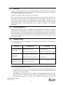
± 2 mm for white surfaces, (+15 °C ... +30 °C)
± 3 mm for natural surfaces, (+15 °C ... +30 °C)
± 4 mm at 0.1 ... 0.5 m range in DS mode, (+15 °C ... +30 °C)
± 5 mm over full temperature range (-40 °C ... +50 °C)
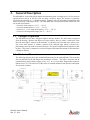
2.1.
Principles of Operation
The AR1000H uses the time of flight of light to measure distance. The laser beam is projected
from the housing’s aperture and shines on a target surface, where it creates a small spot. From
there the laser light is scattered in all directions. A collection lens is located in the sensor to the
side of the laser aperture. It collects a portion of the reflected light, which is focused on a
photodetector and converted to an electrical signal. The signal is amplified and symbolizes a shift
in phase. This phase is compared to a reference signal to determine the amount of shift and hence
a change in distance..
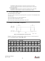
2.2.
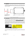
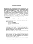
Mechanical Dimensions
The following diagram shows the mechanical dimensions for the small AR1000. The sensor has
four 6.6 mm holes on the side flanges for mounting to a fixture. The cable is for power and all
communication (serial, analog, trigger, power, etc.). It is a 12-pin M18 flange-mount connector
(Binder series 723). The outer case of the sensor is extruded aluminum with powder-coated paint
for corrosion resistance.
AR1000 User’s Manual
Rev 1.7 1/10
4
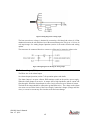
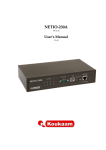
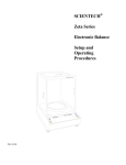
2.3.
Installation
The AR1000 sensor is typically installed by affixing the sensor to a machined bracket with bolts
through the four mounting holes in the sensor. Their location is shown in the mechanical drawing
above. The laser should be aimed at a target such that the distance from the reference point to the
target can be meausured.
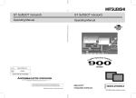
LENS
Laser strikes distant target and
measures the distance based on
the laser reflection returned to
the collection lens.
Figure 1 Zero distance reference point
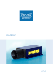
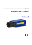
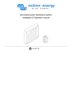
2.4.
Laser Safety
Caution: This laser device should not be aimed at the human eye. Installers of laser sensors
should follow precautions set forth by ANSI Z136.1 Standard for the Safe Use of Lasers or by
their local safety oversight organization. The AR1000 is a class 2 laser product as stipulated in
IEC 60825-1/DIN EN 60825-1:2001-11 and a class II product under FDA 21CFR. In the event of
accidental, short time laser exposure, the human eye is sufficiently protected by its own aversion
response (blinking). This natural reflex may be impaired by medication, alcohol and drugs.
Although the product can be operated without taking special safety precautions, refrain from
directly looking into the laser beam. Do not direct the laser beam at other people to avoid
potential eye hazards.
Figure 2 AR1000 laser safety labels
The laser safety classification reflects worst case situations. User settings or maintenance cannot
increase the level of laser radiation. Do not attempt to loosen any screws or open the sensor
housing.
AR1000 User’s Manual
Rev 1.7 1/10
5
2.5.
Sensor Maintenance
The AR1000 sensor requires little maintenance from the user. The sensor lens should be kept
clean of dust buildup as a part of regular preventative maintenance. Use compressed air to blow
dirt off the window or use delicate tissue wipes. Do not use any organic cleaning solvents on the
sensor. If your sensor does not function according to specifications, contact Schmitt Industries,
Inc. Do not attmept to loosen any screws or open the sensor housing.
2.6.
Sensor Service
The AR1000 sensor is not user-serviceable. Refer all service questions to Schmitt Industries, Inc.
Do not attempt to loosen any screws or open the sensor housing.
2.7.
Sensor Specifications
Go to http://www.acuitylaser.com/pdf/ar1000-data-sheet.pdf
AR1000 User’s Manual
Rev 1.7 1/10
6
3.
Installation and Checkout
3.1.
Mounting
Mount the sensor in such a way that the case is not twisted or warped. Using three hard points
along the front and back edges or a slightly compliant mounting system are the best methods. Do
not clamp or squeeze the sensor case excessively. If the case is distorted, the sensitivity and
accuracy of the sensor may be affected.
3.2.
Cabling
The AR1000 has a multipurpose cable with solder tail wires. The standard cable length is 6.6 feet
(2 m) and longer cable lengths are available. Connection and termination according to the
instructions is essential for correct sensor operation. Read the wire descriptions in Section 4.1for
connection information.
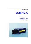
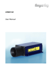
Connect the cable’s 12-pin connector (Binder series 423) to the plug (Binder series 723) on the
back cover of the AR1000 sensor. Be sure to tightly secure the connection.
Figure 3 Back cover with 12-pin plug and pin arrangement
Figure 4 Interface cable
AR1000 User’s Manual
Rev 1.7 1/10
7
3.2.1. Standalone Cabling
To use the AR1000 without a serial connection to a host computer, the only connections
necessary are the power and ground wires, the analog output wires, and optionally the alarm
output wire connecting to your data display, recording, or control equipment. See Signal and
Power Interface (section 4) for wire connections. In its default configuration, the AR1000
does not measure data on power-up.
In 4-20mA analog output mode, the best accuracy and linearity for the current loop is
obtained with a 500-ohm load to current loop return at the measurement point. An out-ofrange current indicates a sensor measurment error.
The alarm output wire can be used to connect to control equipment.
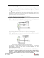
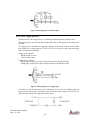
3.2.2. Serial Connection to a Host Computer
RS232: A 9-pin serial D-sub serial connector can be attached to the serial output wires to
connect the AR1000 directly to an IBM-PC compatible 9-pin serial port.
Figure 5 Wiring configuration for 9-pin connector for RS232 serial communications
RS422: An RS422 adapter must be used to connect the AR1000 to an IBM-PC compatible
conputer. The RS422 wires are as follows:
Figure 6 Wiring configuration for RS422 serial communications
For testing use a terminal emulation program such as the Windows® HyperTerminal.
HyperTerminal is included in most versions of Microsoft Windows. To access
HyperTerminal, follow these links:
START > PROGRAMS > ACCESSORIES > COMMUNICATIONS > HYPERTERMINAL
After naming the connection and choosing an icon, choose the COM port that the AR1000 is
connected to. In the next configuration screen, set to 9600 baud, 8 bits, no parity, 1 stop bit
and no flow control to communicate with a sensor in the default configuration.
AR1000 User’s Manual
Rev 1.7 1/10
8
3.3.
Power On
Connect a 15 volt power supply to the power and ground lines of the sensor cable. See Signal and
Power Interface (section 4) for wire connections. Only the power and ground need be connected
for operation in addition to the serial interface.
Caution: be sure that the laser will not cause an eye hazard.
When power is applied the laser beam will be emitted from the laser aperture near the large lens
of the AR1000. The laser beam will be bright red when viewed against a white surface. The
sensor will not transmit measurement readings until a measurement mode is selected. To begin
measuring in Distance Tracking mode, type DT<Enter>. Distance readings will scroll down the
Hpyerterminal window and the default units are be in meters. See section 5.1 for command
information.
3.4.
Verifying Operation
In DT (distance tracking) mode, the AR1000 transmits approximately 6 samples per second at
9600 baud over the serial signals, and transmits measured distance over the current loop output at
the same update rate. The actual measurement speed will depend upon the selected measurement
mode and the reflectance of the target surface. The current loop should put out 4 mA at the near
end of the measurement range, and 20 mA at the far end. Check either, or both, signals to verify
basic sensor operation.
3.5.
Troubleshooting
The sensor displays simple error indications using its function display LEDs. Trouble shooting
steps are shown below:
Symptom
No laser light and no
sample data
Serial port not
responding
Error code (Exx) is
transmitted on serial
port
Possible Cause
Correction
Sampling is turned off
Turn Sampling on
Power supply voltage is too low
Check power supply input voltage
Power supply voltage is too low
Check power supply input voltage
Baud rate incorrect or unknown
See section 3.5.1
See Error codes section 5.3.
3.5.1. Serial Communications Check
If no information is received over the serial port, check the power supply and serial wire
connections. The sensor may be in a configuration that prevents serial communication, such
as being set at the wrong baud rate.
Type PR<Enter> to reset the sensor to the factory defaults (including 9600 baud rate). If the
sensor’s baud rate is unknown, then the PR<Enter> command must be issued from the
hyperterminal program while set at each of the AR1000’s possible baud rates until the
AR1000 User’s Manual
Rev 1.7 1/10
9
AR1000 accepts the command and sets the baud rate to 9600. The possible baud rates are
2400, 4800, 9600, 19200, and 38400.
3.5.2. Sensor Output Check
If the sensor output value is in error, check that the sensor and target are stationary and stable,
that the target is at least 4 inches (0.1 m) from the sensor’s lens, and that the laser beam is
hitting the target.
The distance offset setting may alter the values output by the sensor. Reset the sensor to the
factory default to remove its effect.
The sensor may need to warm up for 5-10 minutes before reaching full accuracy. Leave it on
for a few minutes and re-check the sensor accuracy.
AR1000 User’s Manual
Rev 1.7 1/10
10
4.
Signal and Power Interface
The AR1000 has a multipurpose cable (sensor cable) with solder tail wires. Connection and
termination according to the instructions is essential for correct sensor operation. Read the wire
descriptions for connection information.
Figure 7 AR1000 multipurpose cable with 10 conductors plus shield and corresponding pin arrangments
4.1.
Sensor Cable Wire Colors and Functions
The tables below shows the wiring on systems ordered without power supplies.
Wire
Brown
Red
Orange
White
Grey
Blue
Clear
Pin
C
D
G
H
J
L
Function in All Modes
External Trigger Input (3V to 24 V)
Analog output (4-20 mA current loop)
Supply Voltage +15V (10- 30 VDC)
Alarm Output
Ground (serial)
Ground (Power supply common return)
Shield
The serial communications wires can be used for RS232 or RS422.
Wire
Yellow
Green
Black
Violet
Grey
Pin
B
A
E
F
J
Function in Selected Serial Mode
RS232 models
RS422 models
RxD – Receive Data
RX– : Receive Data –
TxD – Transmit Data
RX+ : Receive Data +
TX- : Transmit Data TX+ : Transmit Data +
Ground (serial)
4.1.1. Power Supply (Orange, Blue)
The Blue wire is the Power Supply Common return, also named Ground. It carries the return
current for the power supply and the analog signals.
The Orange wire is the Power Supply Input to the sensor. The sensor requires +10 VDC
power at 125 mA. The Analog Output uses an additional current up to 25 mA.
AR1000 User’s Manual
Rev 1.7 1/10
11
Power supplies from 10 VDC to 30 VDC may be used. Higher voltages will result in
excessive current drawn by the over-voltage protection circuitry and may cause permanent
damage. Voltages less than 10 VDC may result in inaccurate measurement readings. With
the use of the on-board heater, the AR1000 sensor uses 24 W of power at 24 VDC.
4.1.2. Shield (Clear)
The un-insulated wire is the cable and case shield and is connected to ground inside the
sensor. It should also be connected to ground at the power supply end of the cable.
4.1.3. Serial Communications (Green, Yellow, Black, Violet)
RS232 and RS422 modes are compatible with the associated ANSI standards.
See Serial Interface Operation (section 5) for information on commands and data.
RS232: RS232 is normally used for slower speeds and shorter distances of communications.
A standard 9-pin D-SUB RS232 serial female connector can be built to interface with an IBM
or compatible computer using connection the pins below.
Color
Green
Yellow
Gray
n/c
Pin
2
3
5
1, 4, 6
n/c
7, 8
Trasmit data from sensor
Receive data to sensor
Signal ground reference
DCD, DTE, DCE – These three signals can be tied together to satisfy
some PC signal requirements for hardware handshake.
CTS, RTS – These two signals can be tied together to satisfy some PC
signal requirements for hardware handshake.
RS422: RS422 is normally used for faster speeds and longer distances of communications.
Two wires, usually twisted together, carry each differential (noise-immune) signal. There are
no standard PC connections. A special adapter is required to connect to a PC using RS422.
Color
Green
Yellow
Voilet
Black
Gray
Receive data to sensor (+)
Receive data to sensor (-)
Trasmit data from sensor (+)
Trasmit data from sensor (-)
Signal ground reference
4.1.4. Analog Output (Blue, Red)
The Blue wire is the return signal for the Analog Output. It is connected to ground inside the
sensor and should not be connected to ground outside the sensor. Inadvertently connecting it
to ground may cause a reduction in accuracy of the analog output. The analog signal for
distance is a 4-20 mA current loop. Sensor error signaling can be configured to output either
3 mA or 21 mA.
In Current Loop mode the Red wire delivers a current proportional to the measured distance.
AR1000 User’s Manual
Rev 1.7 1/10
12
Figure 8 Wiring Diagram for Analog output
The best conversion to voltage is obtained by connecting a 500-ohm load resistor (1/4 Watt
minimum) between the red and blue wires at the measurement point. This gives a 2 volt to 10
volt output range. See Analog Output Operation (section 6) for mode selection and scaling
options.
The sensor may be connected directly to a meter or a filter may be inserted to reduce noise.
Figure 9 Wiring Diagram for filtering the Analog output
4.1.5. Alarm Output (White)
The White wire is the Alarm Output.
See Alarm Output Operation (section 7) for operation options and details.
The Alarm Output is an open collector PNP transistor switch to the positive power supply.
When the Alarm Output is not active, its output will be high impedance and no current will
flow through it. When the Alarm Output is active (On) it can source up to 500mA of current.
The load for the output should be connected to ground (Blue wire). The voltage on the Alarm
wire must not exceed the limits of the Power Supply connection voltages (orange and blue
wires), or excessive current may flow into the sensor and cause damage.
AR1000 User’s Manual
Rev 1.7 1/10
13
Figure 10 Wiring diagram for Alarm Output
4.1.6. Laser Trigger (Brown)
The Brown wire is the Trigger input. It is normally left unconnected to enable the laser.
The trigger input is used with the DF measurement mode or TM trigger mode setting in the
AR1000.
The trigger input is intended for triggering a distance measurement with an external signal
that is applied as a voltage between 3 V and 24 V. The user specifies a delay time and trigger
edge for measurement initiation.
Trigger level is defined:
HIGH: Switch is closed.
LOW: Switch is open.
Trigger edge is defined:
Rising edge: Switch closes, input voltage transitions from LOW to HIGH.
Falling edge: Switch opens, input voltage transitions from HIGH to LOW.
Figure 11 Wiring diagram for Trigger Input
If a switch is used, the input may need a debouncing circuit to prevent multiple triggers or
triggers on the wrong edge. This input circuit can be used with a supply from 10V to 30V
(The 1K resistor limits the voltage at the sensor input).
AR1000 User’s Manual
Rev 1.7 1/10
14
5.
Serial Interface Operation
5.1.
Serial Hardware Interface
The serial port hardware is installed either as RS232 (order sensor p/n AP1000232) or RS422
(order sensor p/n AP1000422). The installed serial port hardware can only be selected at the time
of purchasing the AR1000 sensor. The serial port allows full-duplex operation.
5.1.1. Communications Protocol
Serial port communication is required to configure the AR1000 for operation. The easiest
way to commnicate is by using a PC with an RS232 communication port and a terminal
emulation program. The communications protocol is in ASCII format.
Before an operating session begins, users should configure the AR1000 sensor with
parameters that meet the particular measuring site conditions and requirements. All valid
settings will be preserved when the AR1000 sensor is turned off and restored when turned
back on. They can only be replaced with new value entries or changed back to their default
values by communication through the serial port. Below is a short view of the commands
accepted through the AR1000 serial protocol:
Command
ID
DT
DS
DW
DX
DF
DM
TP
SA
SD
ST
SF
SE
AC
AH
AW
HO
HF
RB
RE
RM
TD
TM
BR
AS
OF
Description
Online Help menu
Starts distance tracking
Starts distance tracking 7 m
Starts distance tracking on white target at 10 Hz
Starts distance tracking on white target at 50 Hz
Starts remote-triggered single distance measurement (single shot)
Starts single distance measurement (single shot)
Queries inner temperature
Queries / sets floating average value (1 ...20)
Queries / sets output format (decimel/hex)
Queries / sets time to measure (0...25)
Queries / sets scale factor
Queries / sets error mode (0, 1, 2)
Queries / sets alarm start point
Queries / sets alarm hysteresis
Queries / sets alarm width
Queries / sets heater temperature ON value
Queries / sets heater temperature OFF value
Queries / sets beginning of range (4 mA)
Queries / sets end of range (20 mA)
Queries / sets removal of measured value
Queries / sets trigger delay
Queries / sets trigger mode
Queries / sets baud rate
Queries / sets autostart
Queries / sets offset
AR1000 User’s Manual
Rev 1.7 1/10
15
Command
SO
LO
LF
PA
PR
Description
Sets current distance as offset
Turns laser on
Turns laser off
Displays all parameter values
Resets all parameters to standard values
5.1.2. Baud Rate (BR)
The Baud Rate is selectable via the serial interface and it requires the host device to change
its own Baud Rate after commanding the sensor to change.
The following Baud Rates are provided (with corresponding serial command):
2400
BR2400<Enter>
4800
BR4800<Enter>
9600
BR9600<Enter>
(default)
19200
BR19200<Enter>
38400
BR38400<Enter>
5.2.
Serial Data Output (SD, SF)
The Serial Data Format units, and errors are selectable using the Serial Output Control command.
Serial data is transmitted from the AR1000 as 8 data bits with no parity and 1 stop bit. The
sample data sent represents calibrated distance readings.
Available formats are decimal and hexadecimal
Output units are determined by the scaling factor. The nominal units (scaling factor = 1) is
meters.
Adjustable offset modes are Unbiased, Zero-Based, and Offset-Based.
5.2.1. ASCII Output Format (SDd , SDh or SDs)
The factory default setting for output format is decimal (d)
SD selects between ASCII decimal (d) with distance only, hexadecimal (h) output or ASCII
decimal (s) with both distance and signal strength formats of measured value data. SD affects
all commands that output a distance value.
Decimal Notes:
Decimal (d) output values are based on units of meters (m) multiplied the scale factor SF.
Decimal output has an optional (-) sign, at least one digit before the decimal point, three
digits after the decimal point, and is followed by <CR><LF> (carriage return and line
feed characters).
Decimal (s) output values are xxx.xxx yyyyyy where x is the distance and y is the signal
strength. The range for the signal strength is between 0 ... 999999 and the values depend
on the measurement mode (DT, DS, etc.).
Due to the different calculation algorithms used in the different measurement modes, the
signal strength for a given distance and target surface may be different.
AR1000 User’s Manual
Rev 1.7 1/10
16
The minimum value of 000001 can be reached before the sensor reports an E15 error (see
Error Codes Section 5.3). A maximum signal strength value of 99999 may be reached
before the sensor becomes overloaded with ambient light and reports an E17 error.
Hexadecimal Notes:
Hexadecimal output values are calculated on units of millimeters (mm) multiplied by the
scale factor SF.
Hexadecimal output has a leading space, six hexadecimal digits, and is followed by
<CR><LF> (carriage return and line feed characters).
Negative distance values are output in two’s complement notation.
Hexadecimal output values are limited to six hex digits. A number requiring more than
six digits will be clipped and output only the lower six digits. The clipped number could
therefore exibit an incorrect sign as well as incorrect values. Use the SF command to
keep the output values between hex 800000 (decimal -8388608) and hex 7FFFFF
(decimal 8388607).
Examples:
Distance = 4.996 m, SF1
dec: 4.996
hex: 001384 (hex code for 4996 (mm))
Distance = 4.996 m, SF10
dec: 49.960
hex: 00C328 (hex code for 49960 (4996 mm x scale factor 10))
5.2.2. Serial Data Units or Scale Factor (SFx.x)
The default setting for units is meters (SF1). The output is not labeled.
The AR1000 is capable of reporting data in any units because the user can set a scale factor.
To convert the units to feet, the scale factor would be 3.28084 feet / meter.
Scale factor
Significant digit
Output
SF1
SF3.24084
SF1000
SF3937
0.001 m
0.01 feet
1 mm
0.01 inch
12.345
4.860
12345
39.37
Unit of
Measure
meter
feet
millimeter
inch
5.3. Error Codes
The AR1000 will automatically generate error codes in the ASCII output stream. Some of these
errors may also be represented through the analog and alarm output functions. See the sections
for Current Loop Output and Alarm Output for error handling in those output modes.
Below is a list of the error codes that may be transmitted over the serial output.
Code Description
Remediation
Sensor slow to respond due to low
Use brighter targets or reflective sheeting..
E15 reflectivity or min. range <3.9 in.
Ensure min. range >3.9 in. (0.1m)
(0.1m)
E16 Too much target reflectance
Use darker targets or reflective sheeting
AR1000 User’s Manual
Rev 1.7 1/10
17
Code
E17
E18
E19
E23
E24
E31
E51
E52
E53
E54
E55
E61
E62
E63
E64
Description
Remediation
Reduce ambient light at target and minimize
shiny surfaces
Too much ambient light (sun)
DX mode: measured distance greater
than specified target range
DX mode: target speed > 10 m/s
Temperature below 14°F (-10 °C)
Temperature below 140°F (60 °C)
Faulty memory hardware, EEPROM
error
Check measurement path for obstacles
Reduce relative motion speed of target
Increase ambient temperature to 14°F (-10°C)
Reduce ambient temperature to 140°F (60°C)
Reset parameters. If it persists, contact
technical support
Reduce ambient light. If it persists, contact
High ambient light or hardware error
technical support
Faulty laser diode
Contact technical support
EEPROM parameter not set (ex: Verify the Scale Factor (SF) is not zero.
division by zero)
Contact technical support
Hardware error (PLL)
Contact technical support
Hardware error
Contact technical support
Invalid serial command
Verify command set
Hardware error or Parity error in
Verify Parity = NONE in serial interface
serial communication settings
Check time of emitted signals in application
SIO Overflow
software. Integrate delay on transmission if
necessary
Check format of serial interface: 8 data bits, 1
Framing - error SIO
stop bit, NO Parity (8N1)
5.4. Laser ON and Laser OFF (LO, LF)
5.4.1. Laser ON (LO)
This command turns the laser beam on. This function can be useful for aiming the laser at a
target. The sensor does not measure in this mode.
5.4.2. Laser OFF (LF)
This command turns the laser beam off. The sensor does not measure in this mode.
5.5. Displaying, Configuring and Resetting Parameters (PA, PR, AS, TP)
As the AR1000 sensor is configured for your needs, it may be helpful to view the settings that are
saved in the sensors EEPROM. The PA allows users to view those settings in an online report
through the serial communications interface. The PR command resets all settings to factory
defaults.
5.5.1. Displaying current settings (PA)
The PA command PA<Enter> will display the current settings. An example is shown below:
average value[SA].................1
display format[SD]................d
measure time[ST]..................0
scale factor[SF]..................1
error mode[SE]....................1
AR1000 User’s Manual
Rev 1.7 1/10
18
ALARM center[AC]..................20
ALARM hysterese[AH].............. 0.1
ALARM width[AW]...................10
heating on[HO]....................3
heating off[HF]...................12
distance of Iout=4mA [RB].........15
distance of Iout=20mA [RE]........25
remove measurement [RM]...........0 0 0
trigger delay, trigger level[TD]..0 0
trigger mode, trigger level[TM]...0 1
baud rate[BR].....................9600
autostart command[AS].............ID
distance offset[OF]...............0
5.5.2. Resetting sensor settings (PR)
Typing PR<Enter> will restore the AR1000 to factory default settings.
5.5.3. Autostart configuration (ASxx)
Factory default setting is ID
Autostart defines which function will be carried out when the AR1000 is powered on.
Possible entries are those delivering a measured value on the output side, an ID command or
the command for turning the laser on (LO).
For example, if ASDT<Enter> has been commanded, the AR1000 sensor will begin with
distance tracking after power-up.
Note that the Autostart setting will not operate at power-up if Trigger Mode is ON (TM1 x)
and the trigger condition is not met.
5.5.4. Temperature Display (TP)
The TP<Enter> command displays the AR1000’s internal temperature in Celcius. This may
be helpful information if the sensor will be installed in environments which exceed the
temperature specification for the unit (-10 to 60°C)
5.5.5. Command Display (ID)
The ID<Enter> command displays the AR1000’s command set in the following format.
AR1000 User’s Manual
Rev 1.7 1/10
19
ID[Enter].....................show this list
DT[Enter].....................distance tracking
DS[Enter].....................distance tracking 7m
DW[Enter].....................distance tracking with cooperetive target (10Hz)
DX[Enter].....................distance tracking with cooperetive target (50Hz)
DF[Enter].....................distance measurement with external trigger
DM[Enter].....................distance measurement
TP[Enter].....................internal temperature [C]
SA[Enter] / SAx[Enter]........display/set average value [1..20]
SD[Enter] / SDd[Enter]........display/set display format [d/h]
ST[Enter] / STx[Enter]........display/set measure time [0..25]
SF[Enter] / SFx.x[Enter]......display/set scale factor
SE[Enter] / SEx[Enter]........display/set error mode [0/1/2]
0..Iout=const., ALARM=const.
1..Iout: 3mA @RE>RB, 21mA @RE<RB, ALARM: OFF@AH>0, ON@AH<0
2..Iout: 21mA @RE>RB, 3mA @RE<RB, ALARM: ON@AH>0, OFF@AH<0
AC[Enter] / ACx.x[Enter]......display/set ALARM center
AH[Enter] / AHx.x[Enter]......display/set ALARM hysterese
AW[Enter] / AWx.x[Enter]......display/set ALARM width
HO[Enter] / HOx[Enter]........display/set temperature of heating on [ -40*C ... +70*C]
HF(Enter] / HFx[Enter]........display/set temperature of heating off[ -40*C ... +70*C
RB[Enter] / RBx.x[Enter]......display/set distance of Iout=4mA
RE[Enter] / REx.x[Enter]......display/set distance of Iout=20mA
RM[Enter] / RMx y.y z[Enter]..remove measurement
TD[Enter] / TDx y[Enter]......display/set trigger delay [0..9999ms] trigger level [0/1]
TM[Enter] / TMx y[Enter]......display/set trigger mode [0/1] trigger level [0/1]
BR[Enter] / BRx[Enter]........display/set baud rate [2400..38400]
AS[Enter] / ASd[Enter]........display/set autostart command [DT/DS/DW/DX/DF/DM/TP/LO/ID]
OF[Enter] / OFx.x[Enter]......display/set distance offset
SO[Enter].....................set current distance to offset (offset = - distance)
LO[Enter].....................laser on
LF[Enter].....................laser off
PA[Enter].....................display settings
PR[Enter].....................reset settings
AR1000 User’s Manual
Rev 1.7 1/10
20
6.
Analog Output Operation (RB, RE, SE)
The analog output uses two wires. The output is Red and the return is Blue. The return wire is the
power supply ground. The current loop output is always on.
The analog output is updated with each sample measured. The analog output will deliver a current
which increases linearly from 4 mA at the range beginning point to 20 mA at the range end point.
Best accuracy and noise immunity is obtained by connecting a 500 Ohm resistor to the current return
wire at the measurement point. For connection details, see section 0
6.1.
Setting the analog range beginning point (RB)
The default setting for RB is 1000 (1000 meters is beyond the allowable range of the AR1000)
The parameter units for RB are dictated by the scale factor (SF). See section 5.2.2
The RB, range beginning command, sets the location of the point that is assigned 4 milliamps in
the current loop output. The range beginning point can be set to any distance within the sensor’s
natural measurement range. RB may be greater or less than RE.
6.2.
Setting the analog range end point (RE)
The default setting for RE is 2000 (2000 meters is beyond the allowable range of the AR1000)
The parameter units for RE are dictated by the scale factor (SF).
information about scale factors (SF).
See section 5.2.2 for
The RE, range end, command sets the location of the range ending point sometimes referred to as
the end of the measurement range. The range ending point is assigned 20 milliamps in the current
loop output. The range ending point can be set to any distance within the sensor’s natural
measurement range. RE may be greater or less than RB.
6.3.
Setting the Error Mode (SE0, SE1 or SE2)
The default setting is SE1
The AR1000 can be configured to output analog signals for special error conditions that
correspond to Error Messages E15, E16, E17 and E18 (See Error Messages section 5.3 for more
information).
SE0<Enter> will cause the AR1000 to output and hold the last valid measurement
SE1<Enter> will cause the sensor to output 3 mA if RE>RB and 21 mA if RE<RB
SE2<Enter> will cause the sensor to output 21 mA if RE>RB and 3 mA if RE<RB
The SE command also affects the Alarm output. See section 7.5
AR1000 User’s Manual
Rev 1.7 1/10
21
7.
Alarm Output Operation (AC, AH, AW, SE)
The alarm output uses the white wire in the basic configuration.
Alarm output is also referred to as digital switching output. Users of the AR1000 laser sensor may
wish to monitor the position of an object and receive an alarm if it moves beyond set distance limits.
To do this, users establish parameters of a measurement window using commands AC alarm
commence, AH alarm hysterisis and AW alarm width. The range subject to monitoring begins at AC
and ends at AC+AW. The alarm output transition hysteresis can be set via parameter AH.
The alarm output is updated with each sample measured.
7.1.
Set the alarm start (commence) point (ACx)
The default setting for AC is 1000 (1000 meters is beyond the allowable range of the AR1000)
The units for AC are dictated by the scale factor (SF). See section 5.2.2 for information about
scale factors (SF).
AC sets the beginning of the distance range, for which the alarm output will be turned active. The
length of this active range can be set using the AW parameter.
7.2.
Set the alarm hysteresis (AHx)
The default setting for AH is +0.1
Hysteresis is used to keep the Alarm output state from toggling rapidly near an alarm boundary
becasue the sensor’s measurement ‘noise’ is causes the value to bounce across the boundary.
Hysteresis sets a boundary deadband to keep the Alarm output more stable. The Alarm output is
not allowed to change state as long as the measurement stays within the deadband.
The units for AH are dictated by the scale factor (SF). See section 5.2.2 for information about
scale factors (SF).
AH allows you to make parameter settings for the output transition hysteresis at the beginning
and the end point of the active range of the alarm output.
The mathematical sign of AH is used to set the logic level (HIGH or LOW) of the Alarm state.
Positive sign (“+”): active range is HIGH-active. No sign setting means positively-signed
Negative sign (“-“): active range is LOW-active.
7.2.1. Positive alarm hysteresis
In the case of a positive AH, the output switches
with increasing distance:
from LOW to HIGH if the distance is found to be greater than (AC+AH/2).
from HIGH to LOW if the distance is found to be greater than (AC+AW+AH/2)
with decreasing distance:
from LOW to HIGH if the distance is found to be smaller than (AC+AW-AH/2).
from LOW to HIGH the distance is found to be smaller than (AC-AH/2).
7.2.2. Negative alarm hysteresis
In the case of a negative AH, the output switching pattern will be the opposite of positive.
with increasing distance:
AR1000 User’s Manual
Rev 1.7 1/10
22
from HIGH to LOW if the distance is found to be greater than (AC+AH/2).
from LOW to HIGH if the distance is found to be greater than (AC+AW+AH/2)
with decreasing distance:
from HIGH to LOW if the distance is found to be smaller than (AC+AW-AH/2).
from HIGH to LOW the distance is found to be smaller than (AC-AH/2).
7.3.
Set the alarm window (AW)
The default setting for AW is 100000
The units for AW are dictated by the scale factor (SF). See section 5.2.2 for information about
scale factors (SF).
AW sets the length of the active range, beginning at AC.
AW is always equal or greater than “0” (zero).
AW is always equal or greater than |AH| (absolute value of AH)
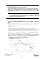
7.4. Example of alarm output configuration
Figure 12 Alarm output behavior with AH+ and AH-
Example: A moving object is monitored within a window of 10 m to 11 m with a hysteresis of
0.2 m. The commands would be: AC10 AH0.2 AW1
Increasing distance (meters)
9.8
9.9
10.0
10.1
10.2
…
11.0
11.1
11.2
11.3
+AH
L
L
L
H
H
H
H
L
L
H
-AH
H
H
H
L
L
L
L
H
H
H
Decreasing distance (meters)
11.3
11.2
11.1
11.0
…
10.2
10.1
10.0
9.9
9.8
+AH
L
L
L
L
H
H
H
H
H
L
-AH
H
H
H
H
L
L
L
L
L
H
AR1000 User’s Manual
Rev 1.7 1/10
23
7.5.
Error Mode behavior for the alarm output (SE0, SE1 or SE2)
The factory default setting is SE1
The AR1000 alarm output can be configured to output different alarm outputs for special error
conditions that correspond to Error Messages E15, E16, E17 and E18 (See Error Messages
section 5.3 for more information).
SE0<Enter> will cause the AR1000 to alarm and hold the output state from the last valid
measurement.
SE1<Enter> will force the following behavior
AH: ALARM=LOW
-AH: ALARM=HIGH
SE2<Enter> will force the following behavior
AH: ALARM=HIGH
-AH: ALARM=LOW
The SE command also affects the Analog output. See section 6.3
AR1000 User’s Manual
Rev 1.7 1/10
24
8.
Performance Optimization
8.1.
Measurement Modes
The AR1000 will not begin measuring and outputting distances until the user selects a
measurement mode. Once initiated, the distance reading will be output on both the serial and
analog lines.
Users may select among several modes that will optimize the sensors’ speed or accuracy
performances for the specific measuring application.
8.1.1. Distance Tracking Mode (DT)
The Distance Tracking mode is a versatile measuring mode that gives priority to the quality
(accuracy) of the measurement rather than a specific measuring rate. In this mode, the actual
sampling time will vary depending on the reflectivity (amplitude of the returning light signal)
of the target. Darker targets may cause longer measuring times.
The minimum time to measure is 160 ms (6Hz), the maximum time is 6 s. If the measuring
signal fails to reach a specified quality within six seconds, an error message is output (see
Error codes 5.3). The time to measure may also be limited by setting the ST parameter to a
desired value.
8.1.2. Close-range Distance Tracking (DS)
The Close-range Distance Tracking mode should be used when measuring varied target
surfaces between 20 to 275 inches (0.5 to 7 m) because it gives better speed performance.
The time to measure may also be limited by setting the ST parameter to a desired value.
8.1.3. 10 Hz Distance Tracking (DW)
The 10 Hz Distance Tracking mode can be selected when working with a cooperative target.
A cooperative target is a target surface with high diffuse reflectivity. Examples of
cooperative targets include white surfaces (paper, paint, etc.) or special reflective targets
(contact technical service). Cooperative targets return strong signals to the AR1000 sensor
and minimize the time required to perform internal algorithms.
In addition to requiring a cooperative target, there may not be jumps in measured distance
greater than 6.3 in. (160 mm) per sample period. The target should not move faster than 5.2
ft/sec (1.6 m/sec).
8.1.4. 50 Hz Distance Tracking (DX)
The 50 Hz Distance Tracking mode can be selected when working with a cooperative target.
A cooperative target is a target surface with high diffuse reflectivity. Examples of
cooperative targets include white surfaces (paper, paint, etc.) or special reflective targets
(contact technical service). Cooperative targets return strong signals to the AR1000 sensor
and minimize the time required to perform internal algorithms.
In addition to requiring a cooperative target, there may not be jumps in measured distance
greater than 6.3 in. (160 mm) per sample period. The target should not move faster than 13
AR1000 User’s Manual
Rev 1.7 1/10
25
ft/sec (4 m/sec). For higher rates of measurement, preceding measured values will be
included in the process to calculate a currently measured value.
8.1.5. Hardware Trigger Mode (DF)
This serial command enables the Trigger input to cause single sample to be measured and
outputs to be generated. The time to measure may also be limited by setting the ST parameter
to a desired value. The maximum suggested trigger is 3.5 Hz (with ST1).
See section 9.2 for Trigger Delay and Edge command (TD) parameters.
Turn the Trigger Mode off when using DF (TM0 x – see section 9.3).
8.1.6. Take Single Sample (DM)
On receipt of this command, a single sample to be measured and outputs is generated. The
time to measure may also be limited by setting the ST parameter to a desired value.
This command does not change any configuration settings.
8.2. Averaging Function (SAx)
Factory default setting is 1.
The SA function commands the sensor to output the average value of the previous 1 to 20
measured values (parameter x has allowed values of 1..20).
Calculation is based on this formula.
8.3. Set Measurement Time (STx)
Factory default setting is 0. This setting affects DT, DS, DF and DM measurement modes.
The ST command allows users to manually set the sample period for the AR1000.
The time required for the AR1000 to take a measurement depends on the selected measurement
mode. Generally, the poorer the surface reflectance of a target, the longer the AR1000 will take to
determine its distance. For example, if error message E15 is output because of poor reflectance
and insufficient time to measure, the ST setting should be increased.
Available ST value range: 0 to 25
x=0
Measurement time is automatic depending on returned signal. The smallest time
possible for attaining a quality measurement is used. The minimum sample
period with ST0 is 240 ms and the maximum sample period is 6 seconds..
x = 1..25 Measurement time is set approximately to:
x * 240ms for DT mode
x * 150ms for DS mode
One use for the ST command is to reduce the data volume or rate by increasing the time per
measurement.
AR1000 User’s Manual
Rev 1.7 1/10
26
8.4. Set Zero Point (OFx)
Factory default setting is 0 (the sensor’s natural zero point)
The OF command allows users to manually set a zero point anywhere relative to the sensor’s
natural zero point. The commanded zero point can be a negative number. The parameter units for
OF are dictated by the scale factor (SF). See section 5.2.2 for information about scale factors
(SF).
8.4.1. Set current distance to Zero (SO)
The SO command performs a distance measurement and saves the measured reading as an
offset value with inverted mathematical sign (OF).
8.5. Filter Measurements (RMx y.y z)
Factory default setting is 0 0 0
Do not use this command when the AR1000 is used to control equipment as it may cause
hazards!
RM is intended to facilitate settings for a range of expected distance values. Values which are
found to be outside of this expected range will be corrected until matching the most recently valid
measured values.
RM is only used in DT mode.
The command’s format consists of three parameters which are separated by space (20h).
x designates the number of preceding measured values that will be evaluated in the case of nonconforming measurement. A maximum of ten preceding measured values can be evaluated.
y defines the range of permissible values. If this range is exceeded in negative or positive
direction, the respective measured value will be corrected accordingly.
z stands for the number of values that are out of the permissible value range (out of tolerance
values). In the event of out-of-tolerance values arriving in succession, the most recently corrected
value will be included in the correction process for the next out-of-tolerance value.
The maximum allowed number of out-of-tolerance values is100.
Example: RM3 0.5 1 (x=3, 2y=1, z=1).
Actual
AR1000 User’s Manual
Rev 1.7 1/10
Limit
27
Corrected
8.6. Set Heater ON Temperature (HOx)
This parameter is only available in the AR1000H laser sensor.
Factory default setting is 3 (corresponding to 3°C)
The HO command determines the low temperature below which the AR1000H sensor’s internal
heater will automatically turn on. A temperature sensor inside the AR1000H monitors the internal
temperature of the device and compares it to the HOx value. If the measured internal temperature
is less than HOx, the heater will be activated. The range of permissible values for the Heater ON
setting is -40 to 70°C
To query the Heater ON temperature without making changes, type HO [enter]
8.7. Set Heater OFF Temperature (HFx)
This parameter is only available in the AR1000H laser sensor.
Factory default setting is 12 (corresponding to 12°C)
The HF command determines the High temperature above which the AR1000H sensor’s internal
heater will automatically turn off. A temperature sensor inside the AR1000H monitors the
internal temperature of the device and compares it to the HOx value. If the measured internal
temperature is greater than HFx, the heater will be de-activated. The range of permissible values
for the Heater ON setting is -40 to 70°C
To query the Heater OFF temperature without making changes, type HF [enter]
AR1000 User’s Manual
Rev 1.7 1/10
28
9.
Trigger Mode Optimization
Trigger mode is only available in the standard AR1000 and NOT available in the AR1000H (heater)
sensor version.
The AR1000 can operate with a hardware trigger that has been connected according to the diagram in
Section 4.1.6. To operate with an external trigger, the AR1000 must be configured in the Trigger
Measurement Mode (DF). See Section 8.1.5 for details about this measurement mode. The Trigger
Delay (TD) and Trigger Mode (TM) functions should only be used in the Hardware Trigger Mode
(DF).
9.1.
Designating Trigger Mode (DF)
DF mode allows a measurement that is triggered by an external trigger pulse. Initially, after
selecting this mode, the operator does not receive any response. As soon as the trigger pulse has
been detected, the AR1000 will send data and update the digital and/or analog output. See TD
(section 9.3) to select the trigger delay and edge.
Note that if TM is on (TM1 x) then the trigger does not always produce the measurement output
in the DF mode. Set TM0 x prior to using DF mode.
9.2.
Setting a Trigger Delay and edge (TDx y)
The factory default setting is 0 0
The Trigger Delay (TDx y) consists of two parameters which are separated by space (20h).
x (0..9999) delay time in milliseconds from trigger edge until measurement is performed.
y (0:falling, 1:rising)
trigger level.
Example:
TD1000 0<Enter>
In the given example, the delay time is set to 1000 ms and the trigger is set to the falling
edge (HIGH to LOW transition).
9.3.
Triggering Autostart (TMx y)
The factory default setting is 0 1.
The Triggering Autostart function allows users to set the hardware trigger to initiate the auto-start
command (set via parameter AS. See Section 5.5.3).
TMx y uses two parameters which are separated by a space (20h).
x (0:no autostart trigger, 1:autostart trigger ON)
y (0: trigger on LOW, 1: trigger on HIGH)
Triggering occurs via the external trigger input. All starting modes which are selectable via AS
can be launched and stopped by external triggering. These are:
DS, DT, DW, DX, DF, DM, TP, LO, and ID.
Normally for triggering, the trigger input must be held in the active state until completion of the
function. If the trigger is in the active state when the TM1 x command is issued, then the function
will activate.
Note that ASDF is not reliable in TM mode, use ASDM instead.
AR1000 User’s Manual
Rev 1.7 1/10
29
9.3.1. Example 1: Triggering Autostart
The Autostart function has the parameters ASDT
The Trigger Autostart has the parameters TM1 1
Trigger signal = High; DT is performed.
Trigger signal = Low; DT is stopped.
Figure 13 Triggering Autostart Low to High
9.3.2. Example 2: Triggering Autostart)
The Autostart function has the parameters ASDM
The Trigger Autostart has the parameter TM1 0
Trigger signal=High; no change in state.
Trigger signal=Low; DM active, i.e. one measurement is triggered.
Figure 14 Triggering Autostart High to Low
AR1000 User’s Manual
Rev 1.7 1/10
30
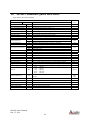
10. Serial Command Quick Reference
Type <Enter> after each command.
AR-1000 Configuration Data Settings (Serial)
Command Name
Serial Command
Online help menu
Distance tracking mode
Close-range distance tracking
10 Hz distance tracking
50 Hz distance tracking
Trigger mode
Take single sample
Temperature display
Averaging function
ASCII output format
Set measurement time
Scale factor
Error mode for Alarm Output
Alarm start point
Alarm hysteresis
Alarm window
Heater ON temperature
Heater OFF temperature
Zero point for Analog output
Span point for Analog output
Filter measurements
Trigger delay for DF mode
Setting a Trigger mode
ID
DT
DS
DW
DX
DF
DM
TP
SAx
SDd
SDh
STx
SFx.x
SE0
SE1
SE2
ACx
AHx.x
AWx.x
HOx
HFx
RBx
REx
RM x y.y z
TDx y
TMx y
Serial Code / Function
Displays serial command menu
Self-adjusting sample period. 6 Hz max
Self-adjusting sample period for ranges < 7 m
10 Hz sampling rate to cooperative target with short movements
50 Hz sampling rate to cooperative target with short movements
External hardware trigger causes a sample to be executed
Serial command to take a single distance reading
Displays AR1000 internal temperature °C
X is an integer 1 to 20. Calculates a floating average
Decimal output
Hexadecimal output
Manually set the sample period 1 to 9999 ms; 0 = self-adjust
Used to obtain output in units other than meters.
Hold last valid measurement
Alarm Low to High
Alarm High to Low
The location where the alarm output activates
Behavior of alarm
Sets the active range for the alarm output
Sets the temperature below which the heater activates (AR1000H only)
Sets the temperature above which the heater de-activates (AR1000H only)
Sets the distance for 4 mA
Sets the distance for 20 mA
Filters z readings outside the window of y.y after evaluating x readings
x = trigger delay (0..9999 ms). y = trigger edge (1:rising, 0:falling)
Delay for x with y edge
2400
BR2400
4800
BR4800
9600
BR9600
19200
BR19200
38400
BR38400
Baud rate
BRx
Autostart configuration
ASx
Configures which modes and parameters will become active after power up of
AR1000
Set zero point
OFx
Sets zero point for serial output with a user-entered number
Set current distance to zero
Turn laser on
Turn laser off
Display current settings
Reset to factory default
SO
LO
LF
PA
PR
Takes a single sample and assigns it the zero point
Turns on laser
Turns off laser
Shows the current parameter settings
Returns all sensor settings to factory default
AR1000 User’s Manual
Rev 1.7 1/10
Factory
Default
31
SA1
SDd
ST0
SF1
SE1
AC1000
AH0.1
AW100000
HO3
RB1000
RE2000
RM0 0 0
TD0 0
TM0 1
BR9600
ASID
(online
menu)
OF0