1
User's
Manual
PR201/UZ005
Power Monitor
Communication Functions
IM 77C01C01-11E
IM 77C01C01-11E
3rd Edition
Blank Page
Introduction
This user's manual describes the communication functions of the Power Monitor and provides
information on how to create communication programs.
The Power Monitor uses the following communication protocols:
1)
2)
3)
4)
Communication protocol for YOKOGAWA´s Power Monitor.
MODBUS communication protocol
PC link communication protocol
LON communication protocol
The Power Monitor cannot communicate with a higher-level device that does not use a communication
protocol the above.
You are required to understand the communication specifications of higher-level devices, as a
background knowledge, in regard to their communication hardware, language used for creating
communication programs, and so on.
* Higher-level devices: PCs, PLCs (sequencers), graphic panels, and others
FD No. IM 77C01C01-11E
1st Edition: Feb. 2001 (YG)
3rd Edition: Jun. 2004 (YK)
All Rights Reserved. Copyright © 2001. Yokogawa Electric Corporation
IM 77C01C01-11E
i
Documentation Conventions
■ Symbols
The following symbols are used in this manual.
● Symbols used in the main text
NOTE
Draws attention to information that is essential for understanding the operation and/or features of the
product.
TIP
Gives additional information to complement the present topic and/or describe terms specific to this
document.
See Also
Gives reference locations for further information on the topic.
● Symbols used in figures and tables
[NOTE]
Draws attention to information that is essential for understanding the operation and/or features of
the product.
[Tip]
Gives additional information to complement the present topic and/or describe terms specific to this
document.
[See Also]
Gives reference locations for further information on the topic.
■ Description of Displays
(1) Some of the representations of product displays shown in this manual may be exaggerated,
simplified, or partially omitted for reasons of convenience when explaining them.
(2) Figures and illustrations representing the controller’s displays may differ from the real displays in
regard to the position and/or indicated characters (upper-case or lower-case, for example), to the
extent that they do not impair a correct understanding of the functions and the proper operation and
monitoring of the system.
NOTE
In this manual, “PT” is used for the same meaning to Voltage Transformer(VT).
ii
IM 77C01C01-11E
Notices
■ Regarding This User's Manual
(1) This manual should be passed on to the end user. Keep this manual in a safe place.
(2) Read this manual carefully to gain a thorough understanding of how to operate this product before
you start using it.
(3) This manual is intended to describe the functions of this product. Yokogawa Electric Corporation
(hereinafter simply referred to as Yokogawa) does not guarantee that these functions are suited to
the particular purpose of the user.
(4) Under absolutely no circumstance may the contents of this manual, in part or in whole, be
transcribed or copied without permission.
(5) The contents of this manual are subject to change without prior notice.
(6) Every effort has been made to ensure accuracy in the preparation of this manual. Should any errors
or omissions come to your attention however, please contact your nearest Yokogawa representative
or our sales office.
■ Regarding Protection, Safety, and Prohibition Against Unauthorized Modification
(1) In order to protect the product and the system controlled by it against damage and ensure its safe
use, make certain that all of the instructions and precautions relating to safety contained in this
document are strictly adhered to. Yokogawa does not guarantee safety if products are not handled
according to these instructions.
(2) The following safety symbols are used on the product and/or in this manual.
● Symbols used on the product and in this manual
CAUTION
This symbol on the product indicates that the operator must refer to an explanation in the user's
manual in order to avoid the risk of injury or death of personnel or damage to the controller. The
manual describes how the operator should exercise special care to avoid electrical shock or other
dangers that may result in injury or loss of life.
Protective Grounding Terminal
This symbol indicates that the terminal must be connected to ground for safety use prior to operating
the equipment.
Functional Grounding Terminal
This symbol indicates that the terminal must be connected to ground for good function prior to
operating the equipment.
● Symbol used in this manual only
WARNING
Indicates that operating the hardware or software in this manner may damage it or lead to system
failure.
IM 77C01C01-11E
iii
■ Force Majeure
(1) Yokogawa does not make any warranties regarding the product except those mentioned in the
WARRANTY that is provided separately.
(2) Yokogawa assumes no liability to any party for any loss or damage, direct or indirect, caused by
the use or any unpredictable defect of the product.
(3) Be sure to use the spare parts approved by Yokogawa when replacing parts or consumables.
(4) Modification of the product is strictly prohibited.
(5) Reverse engineering such as the disassembly or decompilation of software is strictly prohibited.
(6) No portion of the product supplied by Yokogawa may be transferred, exchanged, leased or sublet
for use by any third party without the prior permission of Yokogawa .
iv
IM 77C01C01-11E
PR201 and UZ005 Power Monitors
Communication Functions
IM77C01C01-11E 3rd Edition
Contents
Introduction ................................................................................................................. i
Documentation Conventions .................................................................................... ii
Notices ....................................................................................................................... iii
1.
Communications Overview ........................................................................ 1-1
1.1
1.2
1.3
Overview ......................................................................................................... 1-1
Interface Specifications ................................................................................... 1-1
Setup of RS-485 communication .................................................................... 1-2
1.3.1 Setup Procedure of RS-485 communication ........................................... 1-2
1.3.2 Wiring for RS-485 Communication ........................................................ 1-2
(1) Wiring to a Personal Computer ......................................................... 1-3
(2)Wiring to a PLC (Sequencer) or Graphic Panel ................................ 1-3
1.3.3 Setting Communication Parameters ........................................................ 1-4
(1) Setting Communication Protocols ..................................................... 1-4
(2)Setting Station Number....................................................................... 1-4
(3)Setting Communication Speed ........................................................... 1-4
(4)Setting Higher-level Device Communication Parameters ................. 1-5
1.4 Setup of LON Communication ....................................................................... 1-6
1.4.1 Wiring to a Personal Computer ............................................................... 1-6
1.4.2 Setting Node Number .............................................................................. 1-6
1.4.3 Setting up LON Communication Using an Individual Network Management Tool........... 1-6
2.
Communication Dedicated to Power Monitors ........................................ 2-1
2.1
2.2
2.3
2.4
3.
System Configuration ......................................................................................
Communication Specifications .......................................................................
Commands and Responses ..............................................................................
List of Commands ...........................................................................................
MODBUS Communication ......................................................................... 3-1
3.1
Overview .........................................................................................................
3.1.1 Configuration of Messages ......................................................................
3.2 Communication with Higher-level Device .....................................................
3.2.1 List of Function Codes ............................................................................
3.3 Error Check .....................................................................................................
3.3.1 ASCII Mode ............................................................................................
3.3.2 RTU Mode ...............................................................................................
3.4 Responses from Slaves ...................................................................................
3.4.1 Responses to Normal Messages ..............................................................
3.4.2 Responses to Abnormal Messages ..........................................................
3.5 Commands .......................................................................................................
3.5.1 Function Code 03: Readout of D Registers ............................................
IM 77C01C01-11E
2-1
2-1
2-2
2-4
3-1
3-2
3-3
3-3
3-4
3-4
3-4
3-5
3-5
3-5
3-6
3-6
3.5.2
3.5.3
3.5.4
4.
Function Code 06: Writing to a Single D Register ................................ 3-7
Function Code 08: Loop-back Test ......................................................... 3-8
Function Code 16: Writing to Multiple Data-retaining D Registers ...... 3-8
PC Link Communication ............................................................................ 4-1
4.1
Overview ......................................................................................................... 4-1
4.1.1 Configuration of Commands ................................................................... 4-2
4.1.2 Configuration of Response ...................................................................... 4-3
4.2 Communication with Higher-level Device ..................................................... 4-4
4.3 Response Error Codes ..................................................................................... 4-5
4.4 List of Commands ........................................................................................... 4-6
4.4.1 BRD Reads I relays on a bit-by-bit basis. ........................................... 4-7
4.4.2 BWR Writes data into I relays on a bit-by-bit basis. .......................... 4-8
4.4.3 BRR Reads I relays on a bit-by-bit basis in a random order. ............ 4-9
4.4.4 BRW Writes data into I relays on a bit-by-bit basis in a random order. ..... 4-10
4.4.5 BRS Specifies I relays to be monitored on a bit-by-bit basis. ......... 4-11
4.4.6 BRM Monitors I relays on a bit-by-bit basis. ................................... 4-12
4.4.7 WRD Reads D registers and I relays on a word-by-word basis. ...... 4-13
4.4.8 WWR Writes data into D registers and I relays on a word-by-word basis. ...... 4-14
4.4.9 WRR Reads D registers and I relays on a word-by-word basis in random order. .... 4-15
4.4.10 WRW Writes data into D registers and I relays on a word-by-word basis in random order. ... 4-16
4.4.11 WRS Specifies the D registers and I relays to be monitored on a word-by-word basis. .... 4-17
4.4.12 WRM Monitors the D register and I relays on a word-by-word basis. ....... 4-18
4.4.13 INF Reads the model, version, and revision information. ................ 4-19
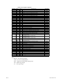
5.
Functions and Usage of D Registers and I Relays ................................... 5-1
5.1
5.2
6.
Functions and Usage of D Registers .............................................................. 5-1
Functions and Usage of I Relays .................................................................... 5-4
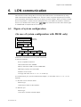
LON communication ................................................................................... 6-1
6.1
6.2
6.3
Figure of system configuration ....................................................................... 6-1
(In case of system configuration with PR201 only) ...................................... 6-1
Communication Specs. .................................................................................... 6-2
Network Variable ............................................................................................ 6-3
IM 77C01C01-11E
Chapter 1 Communications Overview
1.
1.1
Communications Overview
Overview
The Power Monitor has an RS-485 serial communication interface or LON communication interface,
through which data exchange is performed with a device such as a personal computer, PLC
(sequencer), and graphic panel.
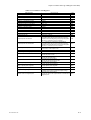
Table 1.1 Communication Protocols
Communication Standards
RS-485 communication
Communication Protocol
Power Monitor communication
PC link communication with sum check
PC link communication without sum check
LON communication
MODBUS communication ASCII mode
MODBUS communication RTU mode
LonTalk protocol
Descriptions
Communication standard used for
power monitor
With error check
Without error check
Communication using ASCII data
Communication using Binary data
Communication capable with LON
supported device
NOTE
Confirm the Model and Specifications.
1.2
Interface Specifications
Table 1.2 Communication Interface Specifications
Interface
Communication
rate
RS-485 communication
1200, 2400
4800, 9600 bps
Maximum: about 1.2 km
Station number: 1 to 31
Data length: 8 bits
Parity: No parity
Start bit: 1
Stop bit: 1
LON communication
78 kbps
Total extended length 500 m,
Maximum node length 400 m
Node number: 1 to 63,
LON standards free topology connection
IM 77C01C01-11E
Communication
distance
Descriptions
1-1
1.3
Setup of RS-485 communication
This chapter describes the procedure to set up the RS-485 communication functions and also refers to
some notes on wiring and communication parameters.
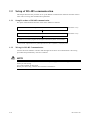
1.3.1
Setup Procedure of RS-485 communication
Set up the communication functions of the Power Monitor as follows:
Connect a higher-level device and a Power Monitor.
(See section 1.3.2.)
Set up the communication parameters of the Power Monitor.
(See section 1.3.3.)
Create communication programs for the higher-level device to perform communication.
* Create communication programs referring to the documentation of each higher-level device.
* In this manual, “higher-level devices” generically denotes PCs, PLCs (sequencers), and graphic panels.
1.3.2
Wiring for RS-485 Communication
Connect the Power Monitor controller and the higher-level device for communication. The wiring
procedures and precautionary notes are as follows.
NOTE
To avoid an electrical shock, be sure to turn off the power supply source to the equipment involved
before you start wiring.
Use crimp terminals at cable ends.
Before you start wiring, read the user's manual of each device.
1-2
IM 77C01C01-11E
Chapter 1 Communications Overview
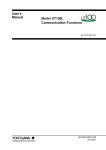
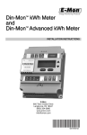
(1) Wiring to a Personal Computer
Since general personal computers cannot directly be connected to the RS-485 interface, wiring must be
provided via an RS-232C/RS-485 converter. The following figures show the wiring for 2-wire
connection.
● 2-wire connection
ML1Terminating
resistor
220Ω1/4W
PC
PR201/UZ005
PR201/UZ005
B(+)
14(+)
A(-)
13(-)
SG
15
Terminating
resistor
220Ω1/4W
RS-232C
straight cable
Communication cable
JIS Class 3 grounding
(grounding resistance
of 100Ω or less)
JIS Class 3 grounding
(grounding resistance
of 100Ω or less)
Communication cable
JIS Class 3 grounding
(grounding resistance
of 100Ω or less)
Note: ML1-■ is the converter of Yokogawa Electric Corporation. You can also use other RS-232C/RS-485 converters. Before
you use another converter, check its electrical specifications.
NOTE
Do not share the grounding wire with another controller. Doing so may result in a failure of the
controller.
Use crimp terminals at the cable ends.
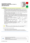
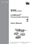
(2)Wiring to a PLC (Sequencer) or Graphic Panel
Since general PLCs (sequencers) and graphic panels have an RS-485 interface, they can be directly
connected to a Power Monitor. If your PLC (sequencer) or graphic panel has an RS-232C interface,
see subsection (1) .
PLC or graphic panel
FAM3
Terminating
resistor
220Ω1/4W
PR201/UZ005
PR201/UZ005
B(+)
14(+)
A(-)
13(-)
SG
15
Communication cable
JIS Class 3 grounding (grounding
resistance of 100Ω or less)
Terminating
resistor
220Ω1/4W
Communication cable
JIS Class 3 grounding (grounding
resistance of 100Ω or less)
Note: In the case of MELSEC (Mitsubishi Electric Corporation´s sequencer), “B” is for (–), and “A” is for (+). In the case of
Graphic panel (Digital Corporation´s), RS232/RS485 converter is needed.
IM 77C01C01-11E
1-3
NOTE
Do not share the grounding wire with another controller. Doing so may result in a failure of the
controller.
Use crimp terminals at the cable ends.
1.3.3
Setting Communication Parameters
This section describes the communication parameters and setting ranges necessary to use the
communication functions.
(1) Setting Communication Protocols
On the power monitor, select the RS-485 communication protocol supported by the higher-level
device.
RS-485 communicationprotocol setting
Power Monitor
communication
Personal computer link
communication without
check sum
MODBOS communication
RTU mode
⭈⭈⭈
,
(2)Setting Station Number
On the power monitor, set the station number. When connecting two or more power monitors to an
integrated RS-485 communication line, make sure none of the station numbers 1 to 31 is set twice.
RS-485 communicationstation number setting
SET/ENT key setting
(3)Setting Communication Speed
On the power monitor, set the communication speed by selecting the baud rate from among 1200,
2400, 4800 and 9600 bps that agrees with the communication speed set in the higher-level device.
RS-485 communicationcommunication speed setting
,
1-4
IM 77C01C01-11E
Chapter 1 Communications Overview
(4)Setting Higher-level Device Communication Parameters
Set the communication parameters of the higher-level device as shown below.
Data length: 8 bits
Parity:
None
Number of start bits: 1
Number of stop bits: 1
See Also
Section 5.3 of the IM77C01C01-01E user's manual for details on how to operate the power monitor.
IM 77C01C01-11E
1-5
1.4
Setup of LON Communication
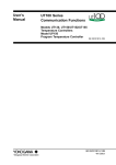
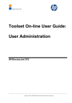
1.4.1
Wiring to a Personal Computer
•Wiring for LON communication
Communication
adapter
Personal computer
5
3
PR201/UZ005
PR201/UZ005
14
14
13
13
NOTE
LON communication does not require consideration of polarity.
1.4.2
Setting Node Number
The Node Number comes factory-set to “Self-installation.” When using the database file provided by
Yokogawa, set the node number on the power monitor. When connecting two or more power monitors to an integrated RS-485 communication line, make sure none of the station numbers 1 to 63 is set
twice.
LON communication
node number setting
SET/ENT
1.4.3
key setting
Setting up LON Communication Using an individual Network Management Tool
Change the nciconfig_mode option of the network variables to EXTERNAL before setting up LON
communication. For details on the setup procedure, see the user's manual of each individual network
management tool.
Note that the node number set in section 1.4.2 becomes void when you carry out this setup procedure.
See Also
Section 6.4 of the IM77C01C01-01E user's manual for details on the communication adapter.
1-6
IM 77C01C01-11E
Chapter 2 Power Monitor communication
2.
Power Monitor communication
Using the command/response method, you can read a variety of measured values onto your personal
computer. Readout can be achieved in two ways: reading measured values one by one or reading the
values at one time (those of measurement data items assigned in the selected parameter).
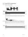
2.1
System Configuration
personal computer
Application software
RS-232C
port
RS-232C/485
converter
Termination
RS-485
Power monitor
Power monitor
Power monitor
Power monitor
Power monitor
Note: It is advisable that for the RS-232C/RS-485 converter, the ML1 from Yokogawa be used in
AUTO mode.
2.2
Communication Specifications
Transmission distance:Approximately 1.2 km maximum
(when 24AWG twisted-pair cable is used)
Connection:
Multi-drop connection of up to 32 stations, including a higher-level personal
computer
Station number:
1 to 31
Transmission method: Half-duplex
Synchronization:
Start-stop synchronization
Transmission rate:
9600, 4800, 2400 or 1200 bps
Data format:
start bi't:
1
Number of data bits:
8
Parity:
None
Number of stop bits:
1
Xon/Xoff control:
None
IM 77C01C01-11E
2-1
Communication error handling:
The power monitor discards a received command and
returns no response if the command is invalid
(ignores electrical noise and faulty commands). Any
time-out process therefore should be run at the
higher-level personal computer. Set the time-out
option to a value no smaller than one second. The
power monitor returns an error response if the
parameter or data is erroneous.
Command/response timing diagram:
Command
Response
8ms or
longer
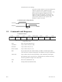
2.3
Commands and Responses
Command elements:
1 byte
2 bytes
1 byte
STX
Command
Parameter
2 bytes
Variable-length
2 bytes
1 byte
1 byte
Data
Check sum
ETX
CR
Station
number
Range of sum check
STX:
Start of Text (hexadecimal: 02)
Command:
2-byte ASCII code (DG or DP)
Parameter:
1-byte ASCII code (0 to X)
Station number:
2-byte ASCII code (01 to 1F)
Data:
Not provided at the time of data readout; provided as variable-length ASCII
code at the time of setpoint change (byte size depends on the type of parameter)
Check sum:
2-byte ASCII code (00 to FF) representing a value obtained by summing the
data within the range of sum check in a hexadecimal way and then converting
the least significant two digits to an ASCII code
2-2
ETX:
End of Text (hexadecimal: 03)
CR:
Carriage Return (hexadecimal: 0D)
IM 77C01C01-11E
Chapter 2 Power Monitor communication
Response elements:
1 byte
2 bytes
1 byte
STX
Response
Parameter
2 bytes
Variable-length
2 bytes
1 byte
1 byte
Data
Check sum
ETX
CR
Station
number
Range of sum check
STX:
Start of Text (hexadecimal: 02)
Response:
2-byte ASCII code (DG or DP)
Parameter:
1-byte ASCII code (0 to Z)
Station number:
2-byte ASCII code (01 to 1F)
Data:
Variable-length ASCII code (byte size depends on the type of parameter)
Check sum:
2-byte ASCII code (00 to FF) representing a value obtained by summing the
data within the range of sum check in a hexadecimal way and then converting
the least significant two digits to an ASCII code
ETX:
End of Text (hexadecimal: 03)
CR:
Carriage Return (hexadecimal: 0D)
An error code may appear on the power monitor in the case of a communication error. If this occurs,
read the error response by sending the parameter Z of the DG command. You can determine details
on the communication error from the content of the error response. Concurrently, the error code on
the power monitor is cleared.
IM 77C01C01-11E
2-3
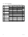
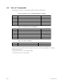
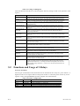
2.4
List of Commands
Table 2.1 Common command for preceding style (PR201S1.0, UZ005S2.0)
ParaDescriptions
meter
0
Measured value read-out
in block
1
2
3
4
5
6
Integrated power read-out
Optional integrated power
read-out *1
Instantaneous power value
read-out
Voltage 1 value read-out
Current 1 value read-out
Optional instantaneous
read-out
7
Optional integration start *1
8
9
Optional integration stop *1
Maximum/minimum values
initialization
Measured Maximum/
minimum values
read-out in block
Voltage 1 maximum value
read-out
Voltage 1 minimum value
read-out
Current 1 maximum value
read-out
Current 2 maximum value
read-out
A
B
C
D
E
2-4
Adaptable model
No optional measuring
Power factor measuring
Current 2 measuring
(preceding value)
(present value)
No optional measuring
Power factor measuring
Current 2 measuring
No optional measuring
Power factor measuring
Current 2 measuring
No current 2 measuring
Current 2 measuring
Response
Response
data format
data range
Data of parameter 1 to 5
Data of parameter 1 to 5 and 6 (Power factor measuring)
Data of parameter 1 to 5 and 6 (Current 2 measuring)
䊐䊐䊐䊐䊐
00000 to 99999[kWh]
䊐䊐䊐䊐䊐
00000 to 99999[Wh]
䊐䊐䊐䊐䊐
00000 to 99999[Wh]
⫾䊐.䊐䊐䊐E⫹䊊
⫾0.001E⫹2 to ⫾9.999E⫹6[W]
Response
data size
40 bytes
46 bytes
48 bytes
5 bytes
10 bytes
䊐.䊐䊐䊐E⫹䊊
䊐.䊐䊐䊐E⫹䊊
No data
䉭䊐.䊐䊐䊐
䊐.䊐䊐䊐E⫹䊊
No data
No data
No data
8 bytes
8 bytes
0 byte
6 bytes
8 bytes
0 byte
0 byte
0 byte
0.001E⫹2 to 9.999E⫹6[V]
0.001E⫹0 to 9.999E⫹6[A]
D0.500 to 1.000 to G0.500
0.001E⫹0 to 9.999E⫹6[A]
9 bytes
Data of parameter 1 to 5 and B to D
Data of parameter 1 to 6 and B to D
Data of parameter 1 to 6 and B to D
䊐.䊐䊐䊐E⫹䊊
0.001E⫹2 to 9.999E⫹6[V]
64 bytes
70 bytes
72 bytes
䊐.䊐䊐䊐E⫹䊊
0.001E⫹2 to 9.999E⫹6[V]
8 bytes
䊐.䊐䊐䊐E⫹䊊
0.001E⫹0 to 9.999E⫹6[A]
8 bytes
No data
䊐.䊐䊐䊐E⫹䊊
8 bytes
0 byte
8 bytes
IM 77C01C01-11E
Chapter 2 Power Monitor communication
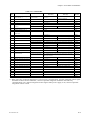
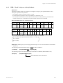
Table 2.2 Command:DG
Response
data format
Response
data range
Parameter
Descriptions
2
Instantaneous optional integrated
(preceding value)
䊐䊐䊐䊐䊐
00000 to 99999[Wh]
power read-out *1
(present value)
䊐䊐䊐䊐䊐
00000 to 99999[Wh]
Adaptable model
Response
data size
10 bytes
3
Power momentary value read-out
⫾䊐.䊐䊐䊐E⫹䊊
⫾0.001E⫹2 to ⫾9.999E⫹6[W]
9 bytes
4
Voltage 1 value read-out
䊐.䊐䊐䊐E⫹䊊
0.001E⫹2 to 9.999E⫹6[V]
8 bytes
5
Current 1 value read-out
䊐.䊐䊐䊐E⫹䊊
0.001E⫹0 to 9.999E⫹6[A]
8 bytes
6
Optional instantaneous value
No optional measuring
No data
read-out
Power factor measuring
䉭䊐.䊐䊐䊐
0 byte
D0.500 to 1.000 to G0.500
6 bytes
7
Optional integration start *1
No data
0 byte
8
Optional integration stop *1
No data
0 byte
9
Maximum/minimum values
No data
0 byte
initialization
B
Voltage 1 maximum value read-out
䊐.䊐䊐䊐E⫹䊊
0.001E⫹2 to 9.999E⫹6[V]
8 bytes
C
Voltage 1 minimum value read-out
䊐.䊐䊐䊐E⫹䊊
0.001E⫹2 to 9.999E⫹6[V]
8 bytes
D
Current 1 maximum value read-out
䊐.䊐䊐䊐E⫹䊊
8 bytes
F
Measured value read-out in block
No optional measuring
0.001E⫹0 to 9.999E⫹6[A]
Data of parameter G,2,3,4,H,J,5,K and L
Power factor measuring
Data of parameter G,2,3,4,H,J,5,K,L and 6 (Power factor measuring)
81 bytes
75 bytes
G
Integrated power read-out
䊐䊐䊐䊐䊐E⫹䊊
00000E⫹3 to 99999E⫹6[Wh]
8 bytes
H
Voltage 2 value read-out
䊐.䊐䊐䊐E⫹䊊
0.001E⫹2 to 9.999E⫹6[V]
8 bytes
J
Voltage 3 value read-out
䊐.䊐䊐䊐E⫹䊊
0.001E⫹2 to 9.999E⫹6[V]
8 bytes
K
Current 2 value read-out
䊐.䊐䊐䊐E⫹䊊
0.001E⫹0 to 9.999E⫹6[A]
8 bytes
L
Current 3 value read-out
䊐.䊐䊐䊐E⫹䊊
8 bytes
M
Measured value Max./min. values
No optional measuring
0.001E⫹0 to 9.999E⫹6[A]
Data of parameter G,2,3,4,H,J,5,K,L and B,C,D and N to T
read-out in block
Power factor measuring
Data of parameter G,2,3,4,H,J,5,K,L and 6 (Power factor measuring)
129 bytes
123 bytes
and B,C,D and N to T
N
Voltage 2 maximum value read-out
䊐.䊐䊐䊐E⫹䊊
0.001E⫹2 to 9.999E⫹6[V]
8 bytes
P
Voltage 3 maximum value read-out
䊐.䊐䊐䊐E⫹䊊
0.001E⫹2 to 9.999E⫹6[V]
8 bytes
Q
Voltage 2 minimum value read-out
䊐.䊐䊐䊐E⫹䊊
0.001E⫹2 to 9.999E⫹6[V]
8 bytes
R
Voltage 3 minimum value read-out
䊐.䊐䊐䊐E⫹䊊
0.001E⫹2 to 9.999E⫹6[V]
8 bytes
S
Current 2 maximum value read-out
䊐.䊐䊐䊐E⫹䊊
0.001E⫹0 to 9.999E⫹6[A]
8 bytes
T
Current 3 maximum value read-out
䊐.䊐䊐䊐E⫹䊊
0.001E⫹0 to 9.999E⫹6[A]
8 bytes
U
---
V
---
W
----
X
Model and specifications read-out
Y
----
Z
Error response
PR201-䊐䊐䊐䊐䊐-䉭䉭,UZ005-䊐䊐䊐䊐䊐-䉭䉭
14 bytes
䊐䊐
2 bytes
*1: When start/stop of optional integration is carried out by communication, optional integrated control signal
thereafter becomes invalid. Therefore, control of optional integration should be done either by
communication or by optional integrated control signal. When power supply is off, control of optional
integration control is reset.
IM 77C01C01-11E
2-5
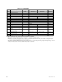
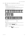
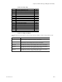
Table 2.3 Command:DP
Parameter
0
1
2
3
4
5
6
7
8
9
A
B
C
D
E
F
G
Descriptions
Set value read-out
------PT ratio setting
CT ratio setting
--------Remote reset
Integrated low-cut power
Integrated pulse unit
ON pulse width of integrated
pulse
Input scaling "L" level setting
for analog output
Input scaling "H" level setting
for analog output
Integration reset
Adaptable
model
Command
data format
No data
Command
data range
(Response *2)
Command
data size
0 byte
䊐䊐䊐䊐䊐
䊐䊐䊐䊐䊐
00001 to 32000
00.05 to 32000
5 bytes
5 bytes
No data
䊐䊐.䊐
䊐.䊐䊐䊐E⫺䊊
䊐䊐䊐䊐
00.1 to 99.9
6.667E⫺6 to 1.000E⫺1
0010 to 1270
0 byte
4 bytes
8 bytes
4 bytes
䉭䊐䊐䊐䊐(䉭:⫹or⫺)
⫺4800 to ⫹4800
5 bytes
䉭䊐䊐䊐䊐(䉭:⫹or⫺)
⫺4800 to ⫹4800
5 bytes
No data (Buffer data is RESET, too.)
0 byte
*2: The response for Set value read-out command is as follows.
PT ratio, CT ratio and Integrated low-cut power 14 bytes (no output option)
PT ratio, CT ratio, Integrated low-cut power, Integrated pulse unit and ON pulse width of integrated pulse
26 bytes (When integrated pulse output is specified)
PT ratio, CT ratio, Integrated low-cut power, Input scaling “L” level setting for analog output and Input scaling “H” level
setting for analog output 24 bytes (When analog output is specified)
2-6
IM 77C01C01-11E
Chapter 3 MODBUS Communication
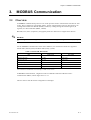
3.
3.1
MODBUS Communication
Overview
A MODBUS communication protocol is one of the protocols used to communicate with devices such
as PCs, PLCs (sequencers), and graphic panels. Via this communication protocol, these devices can
exchange data with Power Monitor (PR201, UZ005) by reading/writing the internal registers (D
registers) of a Power Monitor (PR201, UZ005).
Hereafter, PCs, PLCs (sequencers), and graphic panels are referred to as “higher-level devices.”
See Also
As to configuration of inner registers, refer to "Function and usage of D register and I relay" (Chapter
5).
For the MODBUS communication of the Power Monitor, two transmission modes are supported:
ASCII mode (ASCII system) and RTU mode (binary system).
Table 3.1 ASCII and RTU Modes
Item
ASCII mode
RTU mode
Number of data bits
7 bits (ASCII)
8 bits (binary)
Message start mark
: (colon)
Unnecessary
Message end mark
CR + LF
Unnecessary
Message length (Note 1)
2N + 1
N
Data time intervals
1 second or less
24-bit time or less (Note 2)
Error detection
Longitudinal redundancy check: LRC
Cyclic redundancy check: CRC-16
Note 1: When the message length in the RTU mode is assumed to be “N.”
Note 2: When the communication rate is 9600 bps, 1÷ 9600 × 24 sec. or less.
In MODBUS communication, a higher-level device identifies each Power Monitor with a
communication address, which ranges from 1 to 31.
The next section will discuss the configuration of messages.
IM 77C01C01-11E
3-1
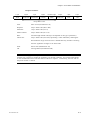
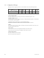
3.1.1
Configuration of Messages
Messages sent from a higher-level device to a Power Monitor consist of the following elements.
Element
Mode
Number of bytes in ASCII mode
Number of bytes in RTU mode
Start of
Message
Mark
Address
Number
(ADR)
Function
Code
Data
Error
Check
End of
Message
Mark
1
1
1
4n
2
2
None
2
2
2n
2
None
(1)
(2)
(3)
(4)
(5)
(6)
(1) Start of Message Mark
This mark indicates the start of a message. Note that only ASCII mode requires a colon.
(2) Address Number (1 to 31)
An address number is used by a higher-level device to identify which Power Monitor to communicate
with. (ID number of Power Monitor)
(3) Function Code (See subsection 3.2.1, “List of Function Codes”)
The function code specifies a command (function code) from the higher-level device.
(4) Data
This element specifies D register numbers, the number of D registers, parameter values, and so on in
accordance with the function code.
(5) Error Check
In ASCII mode carried out by the longitudinal redundancy check (LRC) system.
In RTU mode carried out by the cyclic redundancy check (CRC-16) system.
(6) End of Message Mark
This mark indicates the end of a message.
Note that only ASCII mode requires CR.
3-2
IM 77C01C01-11E
Chapter 3 MODBUS Communication
3.2
Communication with Higher-level Device
When you use a commercially available SCADA or the like or a user-created communication program,
you must be careful when specifying D register numbers contained in messages because in both cases,
you cannot use the original D register numbers as they are.
● To specify D registers
(1) When using a commercially available SCADA or the like, specify D register numbers by changing
them into reference numbers. To change them into a reference number, replace the D register number's
leading character “D” with “4”. (When using a DDE server or others, specify these reference
numbers.)
(2) In a user-created communication program, specify a D register using the hexadecimal number of
the value obtained by subtracting “40001” from the D register's reference number. (Specify this
hexadecimal number.)
Example: To specify “D0101”
• For a message using commercially available SCADA or the like, specify reference number “40101.”
• For a message in a user-created communication program, specify “0064”, the hexadecimal number
of “0100”, which is obtained by subtracting 40001 from the reference number.
3.2.1
List of Function Codes
Function codes are command words used by the higher-level device to obtain the D register
information of Power Monitor.
Table 3.2 Function Codes
Code
03
Function
Reads data from multiple D registers.
Description
Capable of reading data from a maximum of 32 successive registers from
D0001 to D0150.
06
Writes data into D register.
Capable of writing data to one register from D0001 to D0150.
08
Performs loop back test.
See subsection 5.2.3.
16
Writes data into multiple D registers.
Capable of writing data into a maximum of 32 successive registers from D0001
to D0150.
• The write function codes will not write into read-only or disabled D registers.
IM 77C01C01-11E
3-3
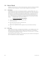
3.3
Error Check
MODBUS communication has two modes: ASCII mode which is ASCII-text communication and RTU
mode which is binary communication. These two modes use different error check methods.
3.3.1
ASCII Mode
In ASCII mode, an error check is run using the LRC method, i.e., logical redundancy check. This
mode calculates the LRC value from the same data as that of the RTU mode. That is, all blocks of a
message, from the slave address to the last data item, except the colon (:), carriage return (CR) and
line feed (LF), are converted one byte hexadecimal data and summed on a byte-by-byte basis. A
two’s complement taken from least sigfinicant two bytes of the value thus obtained equals the LRC
value. At this point, ignore any carry into the most significant digit occurring during the summing.
Example:
Calculating the LRC value when the message is
[:]303530333030363430303032[LRC][CR][LF]
[1] Change the underlined ASCII data to one-byte hex data.
→05, 03, 00, 64, 00, 02
[2] Sum up this one-byte hex data on a byte-by-byte basis.
→05 + 03 + 00 + 64 + 00 + 02 = 6E
[3] Take the two’s complement of the least significant one byte of the data thus summed up.
→92
3.3.2
RTU Mode
In RTU mode, an error check is run using the CRC-16 method, i.e., cyclic redundancy check. In this
method, all blocks of a message, from the slave address to the last data item, are concatenated in
series and the value thus obtained is divided by a predetermined 17-bit binary number. The resulting
16-bit remainder then equals the CRC-16 value.
Note that data subjected to computation is only the value given by the 8-bit block of the message and
does not include the start bit, stop bit, and parity bit.
3-4
IM 77C01C01-11E
Chapter 3 MODBUS Communication
3.4
Responses from Slaves
A power monitor receives a command message from the higher-level device. If the received
command message is found to be normal and directed at the slave address of the power monitor itself,
the power monitor concludes the content of the message to be normal. Thus, the power monitor enters
the phase of executing message processing, deciphers the content of the command message, and
processes with the message.
The power monitor does not execute message processing, however, if the received command message
is found to be abnormal. In that case, the power monitor either ignores the received message or
creates a response message telling the received message is erroneous.
After receiving a normal command message and executing a given process, the power monitor creates
and sends a response message to which error check data appropriate for the command function code of
the higher-level device is added.
3.4.1
Responses to Normal Messages
For a loop back function or a function for writing to a single register, the power monitor returns the
received command message as a response message.
For a function for writing to multiple registers, the power monitor returns part of the received
command message as the response message.
For a readout function, the power monitor adds the read data to the ends of the address number and
function code of the received command message, and returns the message as the response message.
3.4.2
Responses to Abnormal Messages
If there is any failure other than transmission errors, the power monitor returns the following response
message without executing any process:
Address number
Function code + 80H
Error code
Error check data
The following table summarizes details on the error codes.
Error code
Description
01
Function code error (nonexistent error code)
02
Abnormal register number
03
Abnormal number of registers
The power monitor does not regard it as an error even if there is any unused register among those with
consecutive register numbers specified by a read-out function; rather, the power monitor returns a
value of 0 in this case.
The power monitor returns the error code 02 if the first of specified consecutive addresses is made to
fall outside the given range by the number of registers specified, even though it was initially within
the range.
IM 77C01C01-11E
3-5
3.5
Commands
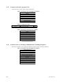
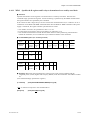
3.5.1
Function Code 03: Readout of D Registers
In the example shown here, the function reads four consecutive registers starting from the register
D0043 of the slave with the slave address 17. Take special note of the fact that the Starting D
Register Number field is set to “42”.
Table 3.3 Message Sent from Mater
Element
Contents
HEX
Start-of-message mark
Address
17
11
03 (=function code)
03
03
Starting D register number
(higher-order)
00
Example for RTU Mode
(24-bit time)
31h
31h
30h
33h
0001 0001
30h
0000 0000
0000 0011
30h
42
Starting D register number
(lower-order)
Example for ASCII mode
(Reference only)
3Ah (: colon)
2A
32h
0010 1010
41h
Number of D register
(higher-order)
00
0000 0000
30h
4 registers
Number of D register
(lower-order)
30h
04
30h
0000 0100
34h
0110 0111
42h
Error check data
=BEh
45h
End-of-message mark
3-6
0Dh(=[CR])
0Ah(=[LF])
=6751h
0101 0001
None
IM 77C01C01-11E
Chapter 3 MODBUS Communication
Table 3.4 Message Sent from Slave
Contents
Element
HEX
Example for ASCII Mode
(Reference only)
Example for RTU Mode
(Reference only)
3Ah (: colon)
(24-bit time)
Start-of-message mark
Address
17
11
03 (= function code)
03
03
31h
31h
30h
33h
Byte count
8 bytes
30h
08
38h
Higher
-order
33h
3F
46h
3F80
Lower
-order
80
Higher
-order
00
38h
30h
30h
30h
0000
Byte count for D
register status
(= number of
registers32)
Lower
-order
00
Higher
-order
3F
30h
30h
80
Higher
-order
00
0000 1000
0011 1111
1000 0000
0000 0000
0000 0000
0011 1111
46h
38h
30h
1000 0000
30h
30h
0000
Lower
-order
0000 0011
33h
3F80
Lower
-order
0001 0001
0000 0000
30h
00
30h
36h
Error check data
36h
=66h
0000 0000
0000 1110
0111 0111
=0E77h
0Dh (=[CR])
End-of-message mark
0Ah (=[LF])
None
* The D register numbers (addresses) are specified using relative addresses.
* The maximum number of D registers that are read is 32.
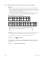
3.5.2
Function Code 06: Writing to a Single D Register
Table 3.5 Message Sent from Master
Start-of-message mark
Address
06 (= function code)
D register number (higher-order)
D register number (lower-order)
Data to write (higher-order)
Data to write (lower-order)
Error check data
End-of-message mark
* Data to write: Optional.
* Specify D register numbers (addresses)
using relative addresses.
Response from Slave
The slave returns the received command message as a response message.
IM 77C01C01-11E
3-7
3.5.3
Function Code 08: Loop-back Test
A loop-back test is used to check signal transmission.
Table 3.6 Message Sent from Higher-level Device
Start-of-message mark
Address
08 (= function code)
Diagnostic code (higher-order) fixed to 00
Diagnostic code (lower-order) fixed to 00
Data (higher-order)
Data (lower-order)
Error check data
End-of-message mark
Table 3.7 Diagnostic Codes
Diagnostic Code
00 00
Meaning
Command message return
Data
Arbitrary
Table 3.8 Message Sent from Power Monitor
Start-of-message mark
Address
08 (= function code)
Diagnostic code (higher-order) fixed to 00
Diagnostic code (lower-order) fixed to 00
Data (higher-order)
Data (lower-order)
Error check data
End-of-message mark
Data: Varies depending on the diagnostic
code sent from higher-level device.
3.5.4
Function Code 16: Writing to Multiple Data-retaining D Registers
This function enables you to change the states of D registers with consecutive addresses.
Table 3.9 Message Sent from Higher-level Device
Start-of-message mark
Address
10 (= function code)
Starting D register number (higher-order)
Starting D register number (lower-order)
Number of registers (higher-order)
Number of registers (lower-order)
Byte count
Data (higher-order)
Data (lower-order)
⭈⭈⭈⭈
Error check data
End-of-message mark
3-8
IM 77C01C01-11E
Chapter 3 MODBUS Communication
Table 3.10 Message Sent from Power Monitor
Start-of-message mark
Address
10 (=function code)
Starting D register number (higher-order)
Starting D register number (lower-order)
Number of registers (higher-order)
Number of registers (lower-order)
Error check data
End-of-message mark
* The maximum number of D registers to
which data are written is 32.
IM 77C01C01-11E
3-9
Blank Page
Chapter 4 PC Link Communication
4.
4.1
PC Link Communication
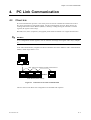
Overview
PC link communication protocol is one of the protocols used to communicate with devices such as
PCs, PLCs (sequencers), and graphic panels. Via this communication protocol, these devices can
exchange data with a Power Monitor (PR201, UZ005) by reading/writing the controller’s internal
registers (D registers and I relays).
Hereafter, PCs, PLCs (sequencers), and graphic panels shall be referred to as “higher-level devices.”
See Also
As to configuration of inner registers, refer to "Function and usage of D register and I relay" (Chapter
5).
In PC link communication, a higher-level device identifies each Power Monitor with a communication
address, which ranges from 1 to 31.
PC
Max. 1200 m; the maximum number of slave units: 31
Power Monitor (PR201, UZ005)
Figure 4.1 Connection of PC Link Communication
The next section will discuss the configuration of commands and responses.
IM 77C01C01-11E
4-1
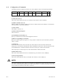
4.1.1
Configuration of Commands
Commands sent from a higher-level device to a Power Monitor consist of the following elements.
Number of bytes
Element
1
2
2
1
3
Address number CPU number Time to wait
STX (Station number)
for response Command
01
0
(1)
(2)
(3)
(4)
Variable length
2
Data corresponding
to command
Check sum
(6)
(7)
(5)
1
1
ETX CR
(8)
(9)
(1) STX (Start of Text)
This control code indicates the start of a command. The character code is CHR$(2).
(2) Address Number (01 to 31)
Address numbers are used by a higher-level device to identify which Power Monitor to communicate
with. (ID number of the Power Monitor)
(3) CPU Number
This number is fixed to 01.
(4) Time to Wait for Response
This is fixed to 0.
(5) Command (See subsection 4.4.)
Specify a command to be issued from the higher-level device.
(6) Data Corresponding to Command
Specify an internal register (D register or I relay), number of data items, Power Monitor's parameter
values, or others.
(7) Check sum
In PC link communication with sum check, the ASCII codes of the text between STX and the
checksum are converted into hexadecimal values and added on a byte basis. Then the lowermost byte
of the added results is turned into ASCII code, and its lower byte is used as the checksum.
This 2-byte space is unnecessary for PC link communication without sum check.
(8) ETX (End of Text)
This control code indicates the end of a command string. The character code is CHR$(3).
(9) CR (Carriage Return)
This control code marks the end of a command. The character code is CHR$(13).
NOTE
The control codes STX, ETX, and CR in commands are indispensable. Do not miss any of them when
you create a communication program for PC link communication. A communication failure will result
if any of them are omitted or if the order is incorrect.
4-2
IM 77C01C01-11E
Chapter 4 PC Link Communication
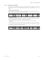
4.1.2
Configuration of Response
Responses from a Power Monitor with respect to a command sent from the higher-level device consist
of the elements shown below, which differ depending on the condition of communication − normal or
failure.
1) With Normal Communication
When communication is carried out normally, the Power Monitor returns the character string “OK”
and, in response to read commands, also returns read-out data.
Number of bytes
1
2
2
2
Variable length
2
Element
STX
Address number
CPU number:
01
OK
Parameter data
Checksum
(Station number)
1
1
ETX CR
2) In the Event of Failure
If communication is carried out abnormally, the Power Monitor returns the character string “ER” and
error codes (EC1 and EC2). (See subsection 4.3, Response Error Codes.)
• No response is made in case of an error in address number specification or CPU number
specification.
• If a Power Monitor cannot receive an ETX contained in a command, a response may not be made.
* As a measure against these situations, provide a timeout processing in the communication functions
or communication programs of the higher-level device.
Number of bytes
1
Element
STX
IM 77C01C01-11E
2
2
Address number CPU number:
(Station number)
01
2
2
(2)
3
2
ER
EC1
(EC2)
Command
Checksum
1
1
ETX CR
4-3
4.2
Communication with Higher-level Device
In PC link communication, when specifying D registers or I relays (internal registers of Power
Monitor), you can use the numbers as is. The numbers of these internal registers are in the following
format:
• D registers:
D**** (****: numeric value)
• I relays:
I**** (****: numeric value)
Higher-level devices to be connected to a Power Monitor are those capable of handling the PC link
communication protocol.
Communication with FA-M3 with UT-link module
No ladder communication program is required to communicate with FA-M3 with UT-link module
(Yokogawa PLC). The UT-link module’s function offers 3 modes, in which users can exchange data
without paying attention to the communication procedure. (For more information, see the user's
manual of UT-link module “IM 34M6H25-01E.”)
●Non-user-specifiable mode: .... Always reads the predetermined devices* of the Power Monitor
(users cannot specify devices).
• Predetermined devices* of Power Monitor: D0001 to D0022
(Since these devices* are in the read only area of Power Monitor, they cannot be written to.)
●User-specifiable mode: ........... Always reads/writes the user-specified devices* of the Power
Monitor.
●Command mode: ..................... Accesses the devices* of the Power Monitor only when necessary.
*: “Predetermined device” or “device” here denotes the internal registers of the Power Monitor (D
registers and I relays).
4-4
IM 77C01C01-11E
Chapter 4 PC Link Communication
4.3
Response Error Codes
The error codes (EC1) and detailed error codes (EC2) of response are as follows.
EC2 is no-meaning when error code (EC1) is not included in following table 4.2.
Table 4.1 Error Codes (EC1)
Error code
Meaning
Causes
02
Command error
• The command does not exist.
• Command not executable
03
Internal register
specification error
• Specified register number does not exist.
• In handling bit registers (I relays) on a word-by-word basis,
its specification is not correct.
04
Out of setting range
• A character other than 0 and 1 was used for bit setting.
• A value other than 0000 to FFFF was specified in the word
specification.
• The start address specified for data loading/saving is out of
the address range.
05
Data number error
• Specified number of bits or words is too large.
• The number of data or registers specified and the number
of parameters for them are inconsistent.
06
Monitor error
• An attempt was made to execute monitoring without
specifying any device to be monitored (BRS or WRS).
08
Parameter error
• Wrong parameter.
42
Sum error
• The sum does not match.
43
Internal buffer overflow
• Too much data was received.
44
Timeout between received
characters
• No terminal character or ETX is received.
Table 4.2 Detailed Error Codes (EC2)
Error code
(EC1)
IM 77C01C01-11E
Meaning
03
Internal register
specification error
04
Out of setting range
05
Data number error
08
Parameter error
Detailed error code (EC2)
Indicates the parameter number where an error occurred
(HEX). This is the number of a parameter in sequence that
first resulted in an error when counted from the leading
parameter.
Error in internal register
Example:
specification
↓
STX 01010WRW 02 D0043, 3F80, A0044, 0000
Parameter number 1
2
3
4
5
In this case, EC1 = 03 and EC2 = 04
4-5
4.4
List of Commands
The following are the lists of commands available in PC link communication.
Table 4.3 Bit-basis Access Commands Dedicated to I Relays
Command
Description
Number of bits handled
BRD
Bit-basis read
1 to 48 bits
BWR
Bit-basis write
1 to 32 bits
BRR
Bit-basis, random read
1 to 16 bits
BRW
Bit-basis, random write
1 to 16 bits
BRS
Specifies I relays to be monitored on a bit-by-bit basis.
1 to 16 bits
BRM
Bit-basis monitoring
—
Table 4.4 Word-basis Access Commands
Command
Description
Number of words handled
WRD
Word-basis read
1 to 64 words
WWR
Word-basis write
1 to 64 words
WRR
Word-basis, random read
1 to 32 words
WRW
Word-basis, random write
1 to 32 words
WRS
Specifies internal registers to be monitored on a word-by-word basis. 1 to 24 words
WRM
Word-basis monitoring
—
Table 4.5 Special Commands
Command
INF
Description
Reads model, version, and revision.
Number of controllers handled
—
The device names (-summary name of D register and I relay -) given as to parameter of command
have following formats.
• D register: Dxxxx (xxxx is D register number.)
• I relay: Ixxxx (xxxx is I relay number.)
4-6
IM 77C01C01-11E
Chapter 4 PC Link Communication
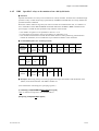
4.4.1
BRD
Reads I relays on a bit-by-bit basis.
● Function
Reads the ON/OFF statuses of a sequence of contiguous I relays by the specified number of bits,
starting at a specified I relay number.
• The number of bits to be read at a time is 1 to 48.
• For the format of response in the event of failure, see subsection 4.1.2.
• The command shown below includes the checksum function. When performing communication
without checksum, do not include the 2-byte checksum element in the command.
● Command/Response (for normal operation)
Number of
Bytes
Command
element
Number of
Bytes
Response
element
1
2
2
1
3
5
1
3
2
1
1
STX
Address
(Station
number)
CPU
number
01
0
BRD
I relay
number
Comma
or space
Number
of bits
(n)
Check
sum
ETX
CR
1
2
2
2
1
1
1
…
1
2
1
1
STX
Address
(Station
number)
CPU
number
01
OK
d1
d2
d3
…
dn
Check
sum
ETX
CR
The response parameter data is “0” when the status is OFF or “1” when ON.
dn: read data of the specified number of bits (n = 1 to 48)
dn = 0 (OFF)
dn = 1 (ON)
● Example: Reading the input overrange against full input scale of the Power Monitor with address
number 01.
The following command reads the status of I0001 at address number 01.
[Command]
[STX]01010BRDI0001, 001[ETX][CR]
The following response is returned with respect to the above command. (When I0001 is ON.)
[Response]
[STX]0101OK1[ETX][CR]
I0001 has been ON since 1 was returned.
IM 77C01C01-11E
4-7
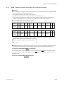
4.4.2
BWR
Writes data into I relays on a bit-by-bit basis.
● Function
Writes ON/OFF data into a sequence of contiguous I relays by the specified number of bits, starting at
a specified I relay number.
• The number of bits to be written at a time is 1 to 32.
• For the format of response in the event of failure, see subsection 4.1.2.
• The command shown below includes a checksum function. When performing communication
without checksum, do not include the 2-byte checksum element in the command.
● Command/Response (for normal operation)
Number of
Bytes
Command
element
1
2
2
1
3
5
1
3
1
1
1
STX
Address
(Station
number)
CPU
number
01
0
BWR
I relay
number
Comma
or space
Number
of bits
(n)
Comma
or space
d1
d2
Command (continued)
…
1
2
1
1
…
dn
Check
sum
ETX
CR
Write information is “0” to set OFF or “1” to set ON.
dn: write data of the specified number of bits (n = 1 to 32)
dn = 0 (OFF)
dn = 1 (ON)
Number of
Bytes
Response
element
1
2
2
2
2
1
1
STX
Address
(Station
number)
CPU
number
01
OK
Check
sum
ETX
CR
● Example: Setting the Remote reset (I0010) of the Power Monitor with address number 01 to ON.
[Command]
[STX]01010BWRI0010, 001, 1[ETX][CR]
“OK” is returned in response to the command above.
[Response]
4-8
[STX]0101OK[ETX][CR]
IM 77C01C01-11E
Chapter 4 PC Link Communication
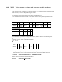
4.4.3
BRR
Reads I relays on a bit-by-bit basis in a random order.
● Function
Reads the ON/OFF statuses of the individual I relays specified in a random order by the specified
number of bits.
• The number of bits to be read at a time is 1 to 16.
• For the format of response in the event of failure, see subsection 4.1.2.
• The command shown below includes a checksum function. When performing communication
without the checksum, do not include the 2-byte checksum element in the command.
● Command/Response (for normal operation)
Number of
Bytes
Command
element
1
2
2
1
3
2
5
1
5
1
STX
Address
(Station
number)
CPU
number
01
0
BRR
Number
of bits
(n)
I relay
number
1
Comma
or space
I relay
number
2
Comma
or space
Command (continued)
…
5
2
1
1
…
I relay
number
n
Check
sum
ETX
CR
1
2
2
2
1
1
…
1
2
1
1
STX
Address
(Station
number)
CPU
number
01
OK
d1
d2
…
dn
Check
sum
ETX
CR
Number of
Bytes
Response
element
The response parameter data is “0” when the status is OFF or “1” when ON.
dn: read data of the specified number of bits (n = 1 to 32)
dn = 0 (OFF)
dn = 1 (ON)
● Example: Reading the Input overrange against full input scale (I0001) and the Remote reset
(I0010) of the Power Monitor with address number 01.
[Command]
[STX]01010BRR02I0001, I0010 [ETX][CR]
In response to the command above, the ON and OFF responses are returned for I0001 and I0010
respectively.
[Response]
[STX]0101OK10[ETX][CR]
I0001 is ON, and I0010 is OFF.
IM 77C01C01-11E
4-9
4.4.4
BRW
Writes data into I relays on a bit-by-bit basis in a random order.
● Function
Writes ON/OFF statuses in the individual I relays specified in a random order by the specified number
of bits.
• The number of bits to be written at a time is 1 to 16.
• For the format of response in the event of failure, see subsection 4.1.2.
• The command shown below includes the checksum function. When performing communication
without the checksum, do not include the 2-byte checksum element in the command.
● Command/Response (for normal operation)
Number of
Bytes
Command
element
1
2
2
1
3
2
5
1
1
1
5
STX
Address
(Station
number)
CPU
number
01
0
BRW
Number
of bits
(n)
I relay
number
1
Comma
or space
d1
Comma
or space
I relay
number
2
Command (continued)
1
1
1
…
5
1
1
2
1
1
Comm
a or
space
d2
Comma
or space
…
I relay
number
n
Comma
or space
dn
Check
sum
ETX
CR
Write information is “0” to set OFF or “1” to set ON.
dn: write data of the specified number of bits (n = 1 to 32)
dn = 0 (OFF)
dn = 1 (ON)
Number of
Bytes
Response
element
1
2
2
2
2
1
1
STX
Address
(Station
number)
CPU
number
01
OK
Check
sum
ETX
CR
● Example: Setting the Remote reset (I0010) and the Stop of optional power integration (I0014) of
the Power Monitor with address number 01 to ON and OFF.
[Command]
[STX]01010BRW02I0010, 1, I0014, 0[ETX][CR]
“OK” is returned in response to the command above.
[Response]
4-10
[STX]0101OK[ETX][CR]
IM 77C01C01-11E
Chapter 4 PC Link Communication
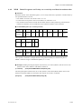
4.4.5
BRS
Specifies I relays to be monitored on a bit-by-bit basis.
● Function
Specifies the numbers of I relays to be monitored on a bit-by-bit basis. Note that this command simply
specifies I relays. Actual monitoring is performed by the BRM command after the I relay numbers are
specified with this command.
When the volume of data is large and you wish to increase the communication rate, it is effective to
use a combination of the BRS and BRM commands rather than the BRD or BRR command. If the
power supply is turned off, the specified I relay numbers will be erased.
• The number of registers to be specified at a time is 1 to 16.
• For the format of response in the event of failure, see subsection 4.1.2.
• The command shown below includes the checksum function. When performing communication
without the checksum, do not include the 2-byte checksum element in the command.
● Command/Response (for normal operation)
Number of
Bytes
Command
element
1
2
2
1
3
2
5
1
5
1
STX
Address
(Station
number)
CPU
number
01
0
BRS
Number
of bits
(n)
I relay
number
1
Comma
or space
I relay
number
2
Comma
or space
Command (continued)
…
…
Number of
Bytes
Response
element
5
2
1
1
I relay
number
n
Check
sum
ETX
CR
1
2
2
2
2
1
1
STX
Address
(Station
number)
CPU
number
01
OK
Check
sum
ETX
CR
● Example: Monitoring the Input overrange against full input scale (I0001) and the Remote reset
(I0010) of the Power Monitor with address number 01.
(This command is used simply for specifying registers.)
[Command] [STX]01010BRS01I0001,I0010[ETX][CR]
“OK” is returned in response to the command above.
[Response] [STX]0101OK[ETX][CR]
IM 77C01C01-11E
4-11
4.4.6
BRM
Monitors I relays on a bit-by-bit basis.
● Function
Reads the ON/OFF statuses of the I relays that have been once specified in advance by the BRS
command.
• Before executing this command, the BRS command must always be executed to specify which I
relays are to be monitored. If no relay has been specified, error code 06 is returned. This error also
occurs if the power supply is turned off.
• For the format of response in the event of failure, see subsection 4.1.2.
• The command shown below includes the checksum function. When performing communication
without the checksum, do not include the 2-byte checksum element in the command.
● Command/Response (for normal operation)
Number of
Bytes
Command
element
Number of
Bytes
Response
element
1
2
2
1
3
2
1
1
STX
Address
(Station
number)
CPU
number
01
0
BRM
Check
sum
ETX
CR
1
2
2
2
1
1
1
…
1
2
1
1
STX
Address
(Station
number)
CPU
number
01
OK
d1
d2
d3
…
dn
Check
sum
ETX
CR
The response parameter data is “0” when the status is OFF and “1” when ON.
dn: read data of the number of bits specified by the BRS command (n = 1 to 16)
dn = 0 (OFF)
dn = 1 (ON)
● Example: Monitoring the Input overrange against full input scale (I0001) and the Remote reset
(I0010) of the Power Monitor with address number 01.
(This command reads the statuses of the I relays specified by the BRS command.)
[Command]
[STX]01010BRM[ETX][CR]
The ON/OFF status of the I relay is returned in response to the command above.
[Response]
[STX]0101OK11[ETX][CR]
The I relay is ON.
4-12
IM 77C01C01-11E
Chapter 4 PC Link Communication
4.4.7
WRD
Reads D registers and I relays on a word-by-word basis.
● Function
Reads a sequence of contiguous register information on a word-by-word basis by the specified number
of words, starting at the specified register number.
• The number of words to be read at a time is 1 to 64.
• For the format of response in the event of failure, see subsection 4.1.2.
• The command shown below includes the checksum function. When performing communication
without the checksum, do not include the 2-byte checksum element in the command.
● Command/Response (for normal operation)
Number of
Bytes
Command
element
1
2
2
1
3
5
1
2
2
1
1
STX
Address
(Station
number)
CPU
number
01
0
WRD
Register
number
Comma
or space
Number
of words
(n)
Check
sum
ETX
CR
1
2
2
2
4
4
…
4
2
1
1
STX
Address
(Station
number)
CPU
number
01
OK
dddd1
dddd2
…
ddddn
Check
sum
ETX
CR
Number of
Bytes
Response
element
The response is returned in a 4-digit character string (0000 to FFFF) in a hexadecimal pattern.
ddddn: Read data of the specified number of words
ddddn = character string in a hexadecimal pattern
n = 1 to 64
● Example: Reading the Integrated power (uint32; lower-order 2 bytes) (D0001) and the Integrated
power (uint32; higher-order 2 bytes) (D0002) of the Power Monitor with address number 01.
[Command] [STX]01010WRDD0001, 02[ETX][CR]
The Integrated power (uint32; lower-order 2 bytes) (D0001) value (03E8(HEX)) and the Integrated
power (uint32; higher-order 2 bytes) (D0002) value (00C8 (HEX)) is returned in response to the
command above.
[Response] [STX]0101OK03E800C8[ETX][CR]
IM 77C01C01-11E
4-13
4.4.8
WWR
Writes data into D registers and I relays on a word-by-word basis.
● Function
Writes information into a sequence of contiguous registers on a word-by-word basis by the specified
number of words, starting at the specified register number.
• The number of words to be written at a time is 1 to 64.
• For the format of response in the event of failure, see subsection 4.1.2.
• The command shown below includes the checksum function. When performing communication
without the checksum, do not include the 2-byte checksum element in the command.
● Command/Response (for normal operation)
Number of
Bytes
Command
element
1
2
2
1
3
5
1
2
1
4
STX
Address
(Station
number)
CPU
number
01
0
WWR
Register
number
Comma
or space
Number
of words
(n)
Comma
or space
dddd1
Command (continued)
4
…
4
2
1
1
dddd2
…
ddddn
Check
sum
ETX
CR
Write information is specified in a 4-digit character string (0000 to FFFF) in a hexadecimal pattern.
ddddn: Write data of the specified number of words
ddddn = character string in a hexadecimal pattern
n = 1 to 64
Number of
Bytes
Response
element
1
2
2
2
2
1
1
STX
Address
(Station
number)
CPU
number
01
OK
Check
sum
ETX
CR
● Example: Writing 0380(HEX) into the PT ratio (float upper 2 bytes) (D0044) and 0000(HEX) into
the PT ratio (float lower 2 bytes) (D0043) of the Power Monitor with address number 01.
[Command]
[STX]01010WWRD0043, 02, 03800000[ETX][CR]
“OK” is returned in response to the command above.
[Response]
4-14
[STX]0101OK[ETX][CR]
IM 77C01C01-11E
Chapter 4 PC Link Communication
4.4.9
WRR
Reads D registers and I relays on a word-by-word basis in random order.
● Function
Reads the statuses of the individual registers, on a word-by-word basis, specified in a random order by
the specified number of words.
• The number of words to be read at a time is 1 to 32.
• For the format of response in the event of failure, see subsection 4.1.2.
• The command shown below includes the checksum function. When performing communication
without the checksum, do not include the 2-byte checksum element in the command.
● Command/Response (for normal operation)
Number of
Bytes
Command
element
1
2
2
1
3
2
5
1
5
1
STX
Address
(Station
number)
CPU
number
01
0
WRR
Number
of words
(n)
Register
number
1
Comma
or space
Register
number
2
Comma
or space
Command (continued)
…
5
2
1
1
…
Register
number
(n)
Check
sum
ETX
CR
Number of
Bytes
Response
element
1
2
2
2
4
4
…
4
2
1
1
STX
Address
(Station
number)
CPU
number
01
OK
dddd1
dddd2
…
ddddn
Check
sum
ETX
CR
The response is returned in a 4-digit character string (0000 to FFFF) in a hexadecimal pattern.
ddddn = character string in a hexadecimal pattern (n = 1 to 32)
● Example: Reading the Integrated pulse Characteristic (int 16 bits) (D0051) and the area for user
(D0104) of the Power Monitor with address number 01.
[Command]
[STX]01010WRR02D0051,D104[ETX][CR]
The Intergrated pulse Characteristic (int 16 bits) (D0051) value 00C8 (HEX) and the area for user
(D0104) value 0032 (HEX) are returned as the response to the above command.
[Response]
IM 77C01C01-11E
[STX]01010OK00C80032[ETX][CR]
4-15
4.4.10 WRW
Writes data into D registers and I relays on a word-by-word basis in random order.
● Function
Writes register information specified for each register into the registers specified in a random order by
the specified number of words.
• The number of words to be written at a time is 1 to 32.
• For the format of response in the event of failure, see subsection 4.1.2.
• The command shown below includes the checksum function. When performing communication
without the checksum, do not include the 2-byte checksum element in the command.
● Command/Response (for normal operation)
Number of
Bytes
Command
element
1
2
2
1
3
2
5
1
4
1
STX
Address
(Station
number)
CPU
number
01
0
WRW
Number
of words
(n)
Register
number
1
Comma
or space
dddd1
Comma
or space
Command (continued)
5
1
4
…
5
1
4
2
1
1
Register
number
2
Comma
or space
dddd2
…
Register
number
n
Comma
or space
ddddn
Check
sum
ETX
CR
Write information is specified in a 4-digit character string (0000 to FFFF) in a hexadecimal pattern.
ddddn: Repetition of register data and write information of the specified number of words
ddddn = character string in a hexadecimal pattern
n = 1 to 32
Number of
Bytes
Response
element
1
2
2
2
2
1
1
STX
Address
(Station
number)
CPU
number
01
OK
Check
sum
ETX
CR
䊉 Example: Writing 0014(HEX) into the area for user (D0104) and 0005(HEX) into the area for user
(D0105) of the Power Monitor with address number 01.
[Command]
[STX]01010WRW02D0104, 0014, D0105, 0005[ETX][CR]
“OK” is returned in response to the command above.
[Response]
4-16
[STX]0101OK[ETX][CR]
IM 77C01C01-11E
Chapter 4 PC Link Communication
4.4.11 WRS
Specifies the D registers and I relays to be monitored on a word-by-word basis.
● Function
Specifies the numbers of the registers to be monitored on a word-by-word basis. Note that this
command simply specifies the registers. Actual monitoring is performed by the WRM command after
the register numbers are specified by this command.
If the volume of data is large and you wish to increase the communication rate, it is effective to use a
combination of the WRS and WRM commands rather than the WRD or WRR command. If the power
supply is turned off, the register numbers specified will be erased.
• The number of words to be specified at a time is 1 to 24.
• For the format of response in the event of failure, see subsection 4.1.2.
• The command shown below includes the checksum function. When performing communication
without the checksum, do not include the 2-byte checksum element in the command.
● Command/Response (for normal operation)
Number of
Bytes
Command
element
1
2
2
1
3
2
5
1
5
1
STX
Address
(Station
number)
CPU
number
01
0
WRS
Number
of words
(n)
Register
number
1
Comma
or space
Register
number
2
Comma
or space
Command (continued)
…
5
2
1
1
…
Register
number
n
Check
sum
ETX
CR
Number of
Bytes
Response
element
1
2
2
2
2
1
1
STX
Address
(Station
number)
CPU
number
01
OK
Check
sum
ETX
CR
● Example: Monitoring the integrated power (uint32; lower-order 2 bytes) (D0001) and the
integrated power (uint32; higher-order 2 bytes) (D0002) of the Power Monitor with address number
01.
(This command simply specifies the registers.)
[Command]
[STX]01010WRS02D0001,D0002[ETX][CR]
“OK” is returned in response to the command above.
[Response]
IM 77C01C01-11E
[STX]0101OK[ETX][CR]
4-17
4.4.12 WRM
Monitors the D register and I relays on a word-by-word basis.
● Function
Reads the information of the registers that have been specified in advance by the WRS command.
• Before executing this command, the WRS command must once be executed to specify which
registers are to be monitored. If no register has been specified, error code 06 is returned. This error
also occurs if the power supply is turned off.
• For the format of response in the event of failure, see subsection 4.1.2.
• The command shown below includes the checksum function. When performing communication
without the checksum, do not include the 2-byte checksum element in the command.
● Command/Response (for normal operation)
Number of
Bytes
Command
element
1
2
2
1
3
2
1
1
STX
Address
(Station
number)
CPU
number
01
0
WRM
Check
sum
ETX
CR
1
2
2
2
4
4
…
4
2
1
1
STX
Address
(Station
number)
CPU
number
01
OK
dddd1
dddd2
…
ddddn
Check
sum
ETX
CR
Number of
Bytes
Response
element
The response is returned in a 4-digit character string (0000 to FFFF) in a hexadecimal pattern.
ddddn: Read data of the number of words specified by the WRS command
ddddn = character string in a hexadecimal pattern
n = 1 to 24
● Example: Monitoring the integrated power (uint32; lower-order 2 bytes) (D0001) and the integrated
power (uint32; higher-order 2 bytes) (D0002) of a Power Monitor with address number 01.
(This command reads the status of the register specified by the WRS command.)
[Command]
[STX]01010WRM[ETX][CR]
The integrated power (uint32; lower-order 2 bytes) (D0001) value 0001 (HEX) and the integrated
power (uint32; higher-order 2 bytes) (D0002) value E02F(HEX) are returned in response to the
command above.
[Response]
4-18
[STX]0101OK0001E02F[ETX][CR]
IM 77C01C01-11E
Chapter 4 PC Link Communication
4.4.13 INF
Reads the model, version, and revision information.
● Function
Reads the model code, version number, and revision number of the Power Monitor.
• For the format of response in the event of failure, see subsection 4.1.2.
● Command/Response (for normal operation)
Number of
Bytes
Command
element
1
2
2
1
3
1
2
1
1
STX
Address
(Station
number)
CPU
number
01
Response
time:
0
INF
6
Check
sum
ETX
CR
1
2
2
2
8
8
4
4
STX
Address
(Station
number)
CPU
number
01
OK
Model and
Option
(Note 1)
Version and
revision numbers
(Note 2)
0001
(Note 3)
0022
(Note 3)
Number of
Bytes
Response
element
Response (continued)
4
4
2
1
1
0001
(Note 3)
0000
(Note 3)
Check
sum
ETX
CR
Note 1: [Model • Option]
When PR201: PR201ⵧⵧⵧ
When UZ005: UZ005ⵧⵧⵧ
Contents of ⵧⵧⵧ:
First column
Phase and wiring system 1; single phase 2 wire,
2; single phase 3 wire, 3; three phase 3 wire and
4; three phase 4 wire
Second column (Reserved) no meaning
Third column Option
0; none, 1; power factor and 2; current 2
Note 2: [Version • Revision] _V**.R**
First column character (i.e. “_” in sample) indicates space.
Note 3: These are manufacture’s matter, so ignore those items.
IM 77C01C01-11E
4-19
Blank Page
Chapter 5 Functions and Usage of D Registers and I Relays
5.
5.1
Functions and Usage of D Registers
and I Relays
Functions and Usage of D Registers
Various types of data are allocated to the D registers of a power monitor. A higher-level device can
acquire data from the power monitor or control the power monitor by accessing these D registers
through MODBUS personal computer link communication.
Table 5.1 D Register Configuration
Register Number
Classification
Description
D0001-D0040
Process data
Measured values, e.g, integrated power
D0043-D0058
Parameter data
Setting condition, e.g, PT and CT ratios
D0059
Setpoint change status
Data serving as a trigger for setpoint change
D0059-D0063
Control data
Control of operations, e.g., remote reset
D0072
Setpoint change status
Switch serving as a trigger for setpoint change
D0073
Integrated value write
status
Switch serving as a trigger for writting
an integrated value
D0101-D0150
User area
Can be used freely by the user.
Others
Prohibited area
Can not be used. Reading from/writing to this area
is not guaranteed.
Table 5.2 D Register Map (1/2)
D-Reg No. Ref No.
IM 77C01C01-11E
H No.
Register Name
Read/Write
D0001
40001
0000
Integrated power (uint32; lower-order 2bytes)
Read
D0002
40002
0001
Integrated power (uint32; higher-order 2bytes)
Read
D0003
40003
0002
Optional integrated power-present send value
(uint32; lower-order 2bytes)
Read
D0004
40004
0003
Optional integrated power-present send value
(uint32; higher-order 2bytes)
Read
D0005
40005
0004
Optional integrated power-previous sent value
(uint32; lower-order 2bytes)
Read
D0006
40006
0005
Optional integrated power-previous sent value
(uint32; higher-order 2bytes)
Read
D0007
40007
0006
Instantaneous value of power (float; lower-order 2bytes)
Read
D0008
40008
0007
Instantaneous value of power (float; higher-order 2bytes)
Read
D0009
40009
0008
Voltage 1 instantaneous value (float; lower-order 2bytes)
Read
D0010
40010
0009
Voltage 1 instantaneous value (float; higher-order 2bytes)
Read
D0011
40011
0010
Voltage 2 instantaneous value (float; lower-order 2bytes)
Read
D0012
40012
0011
Voltage 2 instantaneous value (float; higher-order 2bytes)
Read
D0013
40013
0012
Voltage 3 instantaneous value (float; lower-order 2bytes)
Read
D0014
40014
0013
Voltage 3 instantaneous value (float; higher-order 2bytes)
Read
D0015
40015
0014
Current 1 instantaneous value (float; lower-order 2bytes)
Read
D0016
40016
0015
Current 1 instantaneous value (float; higher-order 2bytes)
Read
D0017
40017
0016
Current 2 instantaneous value (float; lower-order 2bytes)
Read
D0018
40018
0017
Current 2 instantaneous value (float; higher-order 2bytes)
Read
D0019
40019
0018
Current 3 instantaneous value (float; lower-order 2bytes)
Read
D0020
40020
0019
Current 3 instantaneous value (float; higher-order 2bytes)
Read
D0021
40021
0020
Instantaneous value of power factor (float; lower-order 2bytes)
Read
D0022
40022
0021
Instantaneous value of power factor (float; higher-order 2bytes)
Read
D0023
40023
0022
Voltage 1 maximum value (float; lower-order 2bytes)
Read
D0024
40024
0023
Voltage 1 maximum value (float; higher-order 2bytes)
Read
D0025
40025
0024
Voltage 1 minimum value (float; lower-order 2bytes)
Read
D0026
40026
0025
Voltage 1 minimum value (float; higher-order 2bytes)
Read
5-1
Table 5.2 D register map(2/2)
D-Reg No. Ref No.
40027
D0027
40028
D0028
40029
D0029
40030
D0030
40031
D0031
40032
D0032
40033
D0033
40034
D0034
40035
D0035
40036
D0036
40037
D0037
40038
D0038
40039
D0039
40040
D0040
40041
D0041
40042
D0042
40043
D0043
40044
D0044
40045
D0045
40046
D0046
40047
D0047
40048
D0048
40049
D0049
40050
D0050
40051
D0051
40052
D0052
H No.
0026
0027
0028
0029
0030
0031
0032
0033
0034
0035
0036
0037
0038
0039
0040
0041
0042
0043
0044
0045
0046
0047
0048
0049
0050
0051
Register Name
Voltage 2 maximum value (float lower 2 bytes)
Voltage 2 maximum value (float upper 2 bytes)
Voltage 2 minimum value (float lower 2 bytes)
Voltage 2 minimum value (float upper 2 bytes)
Voltage 3 maximum value (float lower 2 bytes)
Voltage 3 maximum value (float upper 2 bytes)
Voltage 3 minimum value (float lower 2 bytes)
Voltage 3 minimum value (float upper 2 bytes)
Current 1 maximum value (float lower 2 bytes)
Current 1 maximum value (float upper 2 bytes)
Current 2 maximum value (float lower 2 bytes)
Current 2 maximum value (float upper 2 bytes)
Current 3 maximum value (float lower 2 bytes)
Current 3 maximum value (float upper 2 bytes)
PT ratio (float lower 2 bytes)
PT ratio (float upper 2 bytes)
CT ratio (float lower 2 bytes)
CT ratio (float upper 2 bytes)
Integrated low-cut power (float lower 2 bytes)
Integrated low-cut power (float upper 2 bytes)
Integrated pulse unit Mantissa (float lower 2 bytes)
Integrated pulse unit Mantissa (float upper 2 bytes)
Integrated pulse unit Characteristic (int 16 bits)
Integrated pulse ON pulse width (uint 16 bits)
Input scaling "L" level for analog output
(float lower 2 bytes)
Input scaling "L" level for analog output
(float upper 2 bytes)
Input scaling "H" level for analog output
(float lower 2 bytes)
Input scaling "H" level for analog output
(float upper 2 bytes)
Integrated power setting (uint 32 lower 2 bytes)
Integrated power setting (uint 32 upper 2 bytes)
Remote reset
Integrated power reset
Maximum/Minimum value reset
Start of optional integrated power
Stop of optional integrated power
Read/Write
Read
Read
Read
Read
Read
Read
Read
Read
Read
Read
Read
Read
Read
Read
Read/Write
Read/Write
Read/Write
Read/Write
Read/Write
Read/Write
Read/Write
Read/Write
Read/Write
Read/Write
Read/Write
D0053
40053
0052
D0054
40054
0053
D0055
40055
0054
D0056
40056
0055
D0057
D0058
D0059
D0060
D0061
D0062
D0063
D0065
D0072
D0073
D0074
D0075
40057
40058
40059
40060
40061
40062
40063
40065
40072
40073
40074
40075
0056
0057
0058
0059
0060
0061
0062
0064
0071
0072
0073
0074
D0101
40101
0100
Area for user
Read/Write
D0150
40150
0149
Area for user
Read/Write
Status of setting change
Status of write-in integrated power
Read/Write
Read/Write
Read/Write
Write
Write
Write
Write
Write
Write
Write
Write
Write
Note:
Ref No.: For SCADA program
H No.: For user created program
float : single precision floating decimal point
uint : without sign integer
int : with sign integer
5-2
IM 77C01C01-11E
Chapter 5 Functions and Usage of D Registers and I Relays
Table 5.3 Parameters of D Registers
Parameter Name
Range and Unit
Type
Integrated power
0-99999999kWh
uint32
Optional integrated power-present send value
0-99999Wh
uint32
Optional integrated power-previous sent value
0-99999Wh
uint32
Instantaneous value of power
0 to 69999MW
float
Voltages 1-3 instantaneous values
0-9999kV
float
Currents 1-3 instantaneous values
0-9999kA
float
Instantaneous value of power factor
-0.5 to +0.5
float
Voltages 1-3 maximum values
0-9999kV
float
Voltages 1-3 minimum values
0-9999kV
float
Currents 1-3 maximum values
0-9999kA
float
PT ratio
1-32000
float
CT ratio
0.05-32000
float
Integrated low-cut power
0.1-99.9
float
Integrated pulse unit
6.667310-6 to 1.000310-1
float
Integrated pulse unit mantissa
1.000 to 9.999. Assuming the mantissa and characteristic of
an integrated pulse unit are a and b respectively, then the
parameter value must fall within the range of the integrated
pulse unit, i.e., 6.667310-6⬉a⫻10b⬉1.000310-1.
float
Integrated pulse unit characteristic
-6 to -1. Assuming the mantissa and characteristic of
an integrated pulse unit are a and b respectively, then the
parameter value must fall within the range of the integrated
pulse unit, i.e., 6.667310-6⬉a⫻10b⬉1.000310-1.
int16
Integrated pulse ON pulse width
1 to 127. This range is equivalent to 10 to
1270 ms since 1 count equals 10 ms.
int16
Input scaling L for analog output
-4800 to +4800
float
Input scaling H for analog output
-4800 to +4800
float
Remote reset
Value other than 1: Does nothing.
1: Resets the power monitor.
int16
Integrated power reset
Value other than 1: Does nothing.
1: Resets the integrated power.
int16
Maximum/minimum value reset
Value other than 1: Does nothing.
1: Resets the maximum/minimum value.
int16
Start of optional power integration
Value other than 1: Does nothing.
1: Starts optional power integration.
int16
Stop of optional power integration
Value other than 1: Does nothing.
1: Stops optional power integration.
int16
Integrated power setting
0-99999999999 kWh
int32
Status of setting change
Value other than 1: Does nothing.
1: Initializes the D register to reflect the setpoint change.
int16
Status of write-in integrated power
Value other than 1: Does nothing.
1: Writes the values of the registers D0057 and D0058 as the
integrated power.
int16
IM 77C01C01-11E
5-3
Table 5.4 Change in D Registers
(This table describes the behavior of each D register when any change is made to the parameter of the
register.)
Changed Parameter
5.2
Behavior When Parameter Is Changed
PT ratio
This change only results in the saving of the setpoint in the buffer memory of the power
monitor; no change is made to the PT ratio until the status of setting change switches to
CT ratio
This change only results in the saving of the setpoint in the buffer memory of the power
monitor; no change is made to the CT ratio until the status of setting change switches to
Integrated low-cut
power
This change only results in the saving of the setpoint in the buffer memory of the power
monitor; no change is made to the integrated low-cut power until the status of setting
change switches to 1.
Integrated pulse unit
This change only results in the saving of the setpoint in the buffer memory of the power
monitor; no change is made to the integrated pulse unit until the status of setting change
switches to 1.
Integrated pulse ON
pulse width
This change only results in the saving of the setpoint in the buffer memory of the power
monitor; no change is made to the integrated pulse ON pulse width until the status of
setting change switches to 1.
Input scaling L for
analog output
This change only results in the saving of the setpoint in the buffer memory of the power
monitor; no change is made to the analog output scaling L until the status of setting change
switches to 1.
Input scaling H for
analog output
This change only results in the saving of the setpoint in the buffer memory of the power
monitor; no change is made to the analog output scaling H until the status of setting change
switches to 1.
Status of setting change
This change initializes operating conditions with setpoints saved in the storage buffers of
the power monitor when the parameter is set to 1, so that these setpoints are incorporated
into power monitor operation.
Remote reset
This change causes the power monitor to reset itself for restart immediately after returning
a response message when it receives 1 as the setpoint.
Integrated power reset
This change causes the power monitor to reset the integrated power immediately after
returning a response message when it receives 1 as the setpoint.
Maximum/minimum
value reset
This change causes the power monitor to reset the maximum/minimum value immediately
after returning a response message when it receives 1 as the setpoint.
Start of optional power
integration
This change causes the power monitor to start optional power integration immediately after
returning a response message when it receives 1 as the setpoint. This setting change is
ignored if integration has already started.
Stop of optional power
integration
This change causes the power monitor to stop optional power integration immediately after
returning a response message when it receives 1 as the setpoint. This setting change is
ignored if integration has already stopped.
Integrated power setting
This change only results in the saving of the setpoint in the buffer memory of the power
monitor; no change is made to the integrated power setting until the status of write-in
integrated power switches to 1. No change is made to the integrated power even if the
status of setting change switched to 1, however, in the case where this parameter is set
to 0xFFFFFFFF.
Functions and Usage of I Relays
Overview of I Relays
Various types of information and control functions are allocated to the I relays of a power monitor. A
higher-level device can acquire data from the power monitor or control the power monitor by accessing these I relays through MODBUS personal computer link communication.
Table 5.5 I Relay Configuration
I Relay Number
5-4
Classification
Description
1, 2
Error information
Error related to input overranges
10-14
Control data
Control of operations, e.g., remote reset
101-164
User area
Can be used freely by the user.
Others
Prohibited area
Cannot be used. Reading from/writing to this area is not guaranteed.
IM 77C01C01-11E
Chapter 5 Functions and Usage of D Registers and I Relays
Table 5.6 I Relay Map
Relay No.
Relay Name
Read/Write
1
Input overrange against full input scale
Read
2
Input overrange against analog output scaling
Read
10
Remote reset
Write
11
Integrated power reset
Write
12
Maximum/minimum value reset
Write
13
Start of optional power integration
Write
14
Stop of optional power integration
Write
3
4
5
6
7
8
9
15
101
User area
Read/Write
164
User area
Read/Write
Table 5.7 Change in I Relays
(This table describes the behavior of each I relay when any change is made to the parameter of the
relay.)
Changed Parameter
Behavior When Parameter Is Changed
Remote reset
This change causes the power monitor to reset itself for restart immediately after
returning a response message when it receives 1 as the setpoint.
Integrated power reset
This change causes the power monitor to reset the integrated power immediately
after returning a response message when it receives 1 as the setpoint.
Maximum/minimum
value reset
This change causes the power monitor to reset the maximum/minimum value
immediately after returning a response message when it receives 1 as the setpoint.
Start of optional power
integration
This change causes the power monitor to start optional power integration
immediately after returning a response message when it receives 1 as the setpoint.
This setting change is ignored if the integration has already started.
Stop of optional power
integration
This change causes the power monitor to stop optional power integration
immediately after returning a response message when it receives 1 as the setpoint.
This setting change is ignored if integration has already stopped.
IM 77C01C01-11E
5-5
Blank Page
Chapter 6 LON communication
6.
LON communication
The read out of various setting data can be easily done without notice of communication,by using
LON communication adapter and DDE server. Also the control of optional integrated power and the
reset of maximum and minimum values can be done by personal computer. When you connect another
device except PR201 or UZ005, Network management tool ("Lon Maker for Windows" of Echelon
and so on) is needed. In this ocasion, press
+
keys within three seconds. Then monitor lights
on COMM LED in red,and sends service message.
6.1
Figure of system configuration
(In case of system configuration with PR201 only)
Personal
Computer
Application Softwaer
DDE Server
Data Base
LON Communication
Adapter
LON
Power
Monitor
Power
Monitor
Power
Monitor
Power
Monitor
Power
Monitor
F04.EPS
Instruments recommended to use for system construction:
(1) Personal Computer
PC/AT compatible instrument
CPU Pentium more than 100MHz
Memory more than 16MB 3.5 inch 1.44MB FDD
HDD empty capacity more than 6MB
Windows Version 95/98
Can equip with either one of <1> <2> <3> of Item (2)
(2) Communication port, slot and communication adapter (<4> and either one of <1> <2> <3> are
required)
<1> PCI Slot to store extension board
Echelon Type
74401 PCLTA-20/FT-10 PCI Interface
<2> RS-232C port
Echelon type
73351 SLTA-10 Serial LonTalk Adapter
IM 77C01C01-11E
6-1
<3> PCMICA Slot
Echelo Type
73200 PCC-10 PC Card Network Adaptor
78302-2 Conductor Cable Assembly
<4> Driver Soft for above <1> to <3>
Echelon Type
58030-01 Connectivity Starter Kit
(3) Application Software
Software for Microsoft Windows with DDE function (Microsoft Type Microsoft Excel, Visual
Basic or various SCADA softwares.), Echelon Type LonMaker for windows and others.
6.2
Communication Specs.
Transmit distance: Total extension 500 m, Between node max. 400 m
(When use of 22AWG twist pair cable)
Connecting mode:
• LON standrd Freetopology connection
Max. 64 node (including upper computer)
• Terminating resistor: 51 Ω (one end)
• Transformer insulation (FTT-10A)
Connecting Terminal:
3 terminals back face
A,B: Balanced type twist paircable
C: Shield
Node No.: 1 to 63
Transmit mode: Half duplex communication
Transmit speed: 78 kbps
Data format: LonTalk protocol standard
Error detect: CRC check
6-2
IM 77C01C01-11E
Chapter 6 LON communication
6.3
Network Variable
Actual communication is carried out by DDE server. By means of accessing to the Network variable
from Microsoft Windows software with DDE function, read-out of various setting values and reset of
optional integrated power and maximum/minimum values can be done from personal computer.
Variables meaning
Type declaration
Variable names
Range
Integrated power output
network output SVNT_elec_whr_f
nvoe1
00000 to 99999[kWh]
Optional integrated power present send
network output SVNT_elec_whr_f
nvoe2
00000 to 99999[Wh]
network output SVNT_elec_whr_f
nvoe3
00000 to 99999[Wh]
Integrated power value output
network output SVNT_elec_whr_f
nvoe4
00000 to 99999999000[Wh]
Instantaneous power output
network output SVNT_power_f
nvop
±0.001E+2 to ±9.999E+6[W]
Voltage 1 value output
network output SVNT_volt_f
nvov1
0.001E+2 to 9.999E+6[V]
Voltage 2 value output
network output SVNT_volt_f
nvov2
0.001E+2 to 9.999E+6[V]
Voltage 3 value output
network output SVNT_volt_f
nvov3
0.001E+2 to 9.999E+6[V]
Current 1 value output
network output SVNT_amp_f
nvoi1
0.001E+0 to 9.999E+3[A]
Current 2 value output
network output SVNT_amp_f
nvoi2
0.001E+0 to 9.999E+3[A]
Current 3 value output
network output SVNT_amp_f
nvoi3
0.001E+0 to 9.999E+3[A]
Instantaneous power factor output
network output SVNT_pwr_fact_f
nvopf
–0.500 to 1.000 to +0.500[cos ø]
Voltage 1 maximum value output
network output SVNT_volt_f
nvomaxv1
0.001E+2 to 9.999E+6[V]
Voltage 2 maximum value output
network output SVNT_volt_f
nvomaxv2
0.001E+2 to 9.999E+6[V]
Voltage 3 maximum value output
network output SVNT_volt_f
nvomaxv3
0.001E+2 to 9.999E+6[V]
Voltage 1 minimum value output
network output SVNT_volt_f
nvominv1
0.001E+2 to 9.999E+6[V]
Voltage 2 minimum value output
network output SVNT_volt_f
nvominv2
0.001E+2 to 9.999E+6[V]
Voltage 3 minimum value output
network output SVNT_volt_f
nvominv3
0.001E+2 to 9.999E+6[V]
Current 1 maximum value output
network output SVNT_amp_f
nvomaxi1
0.001E+0 to 9.999E+3[A]
Current 2 maximum value output
network output SVNT_amp_f
nvomaxi2
0.001E+0 to 9.999E+3[A]
Current 3 maximum value output
network output SVNT_amp_f
nvomaxi3
0.001E+0 to 9.999E+3[A]
Integrated power send period input
network input SVNT_elapsed_tm
nciinterval1
0 to 59[min] 0 to 59[sec]
Instantaneous value send period input
network input SVNT_elapsed_tm
nciinterval2
0 to 59[min] 0 to 59[sec]
Maximum & minimum value send
network input SVNT_elapsed_tm
nciinterval3
0 to 59[min] 0 to 59[sec]
Integrated power reset input
network input SVNT_count
nviereset
1: reset of integrated value (reset holding data too)
Optional integrated power control input
network input SVNT_count
nvicontrole2
0: Option integration stop 1: Optional integration start
Maximum & minimum value reset input
network input SVNT_count
nviresetmax
1: Maximum/Minimum value reset
Integrated power send request input
network input SVNT_count
nvireqe1
1: Integrated power send request
Optional integrated power present value
network input SVNT_count
nvireqe2
1: Optional integrated power present value send request
network input SVNT_count
nvireqe3
1: Optional integrated power preceding value send request
Instantaneous power send request input
network input SVNT_count
nvireqp
1: Instantaneous power send request
Voltage 1 send request input
network input SVNT_count
nvireqv1
1: Voltage 1 send request
Voltage 2 send request input
network input SVNT_count
nvireqv2
1: Voltage 2 send request
Voltage 3 send request input
network input SVNT_count
nvireqv3
1: Voltage 3 send request
Current 1 send request input
network input SVNT_count
nvireqi1
1: Current 1 send request
Current 2 send request input
network input SVNT_count
nvireqi2
1: Current 2 send request
Current 3 send request input
network input SVNT_count
nvireqi3
1: Current 3 send request
Instantaneous power factor send request input network input SVNT_count
Voltage 1 maximum value send request input network input SVNT_count
nvireqpf
1: Instantaneous power factor send request
nvireqmaxv1
1: Voltage 1 maximum value send request
Voltage 2 maximum value send request input
network input SVNT_count
nvireqmaxv2
1: Voltage 2 maximum value send request
Voltage 3 maximum value send request input
network input SVNT_count
nvireqmaxv3
1: Voltage 3 maximum value send request
Voltage 1 minimum value send request input
network input SVNT_count
nvireqminv1
1: Voltage 1 minimum value send request
Voltage 2 minimum value send request input
network input SVNT_count
nvireqminv2
1: Voltage 2 minimum value send request
Voltage 3 minimum value send request input
network input SVNT_count
nvireqminv3
1: Voltage 3 minimum value send request
Current 1 maximum value send request input
network input SVNT_count
nvireqmaxi1
1: Current 1 maximum value send request
Current 2 maximum value send request input
network input SVNT_count
nvireqmaxi2
1: Current 2 maximum value send request
Current 3 maximum value send request input
network input SVNT_count
nvireqmaxi3
1:Current 3 maximum value send request
value output
Optional integrated power previous sent
value output
periodical input
send request input
Optional integrated power previous value
sent request input
IM 77C01C01-11E
6-3
Buffer type
Buffer Type
Application input buffers
Application output buffers
Application priority output buffers
Network input buffers
Network output buffers
Network priority output buffers
Receive transaction buffers
Transmit transaction buffers
TOTAL USED
6-4
Default Count
15
3
2
11
5
2
16
2
56
Default Size
22
20
20
66
42
42
13
28
253
IM 77C01C01-11E
YOKOGAWA ELECTRIC CORPORATION
Network Solutions Business Division
2-9-32, Nakacho, Musashino-shi, Tokyo, 180-8750 JAPAN
Phone: +81-422-52-7179 Facsimile: +81-422-52-6793
Sales Branch Offices
Tokyo, Nagoya, Osaka, Hiroshima, Fukuoka
YOKOGAWA CORPORATION OF AMERICA
Headquaters
2 Dart Road, Newnan, GA. 30265-1094 U.S.A.
Phone: +1-770-253-7000 Facsimile: +1-770-251-0928
Sales Branch Offices / Texas, Chicago, Detroit, San Jose
YOKOGAWA EUROPE B. V.
Headquaters
Databankweg 20, 3821 AL Amersfoort THE NETHERLANDS
Phone: +31-334-64-1611 Facsimile: +31-334-64-1610
Sales Branch Offices / Houten (The Netherlands), Wien (Austria), Zaventem
(Belgium), Ratingen (Germany), Madrid (Spain), Bratislava (Slovakia), Runcorn (United
Kingdom), Milano (Italy), Velizy villacoublay(France), Johannesburg(Republic of South
Africa)
YOKOGAWA AMERICA DO SUL S.A.
Headquarters & Plant
Praca Acapulco, 31-Santo Amaro, Sao Paulo/SP, BRAZIL CEP-04675-190
Phone: +55-11-5681-2400 Facsimile: +55-11-5681-4434
YOKOGAWA ENGINEERING ASIA PTE. LTD.
Head office
5 Bedok South Road, Singapore 469270 SINGAPORE
Phone: +65-6241-9933 Facsimile: +65-6241-2606
YOKOGAWA ELECTRIC KOREA CO., LTD.
Seoul Sales office
395-70, Shindaebang-dong, Dongjak-gu, Seoul,156-010, KOREA
Phone: +82-2-3284-3000 Facsimile: +82-2-3284-3019
YOKOGAWA TAIWAN CORPORATION
Head office
17F, No.39, Sec. 1, Chung Hwa Road Taipei, 100 TAIWAN
Phone: +886-2-2314-9166 Facsimile: +886-2-2314-9918
YOKOGAWA AUSTRALIA PTY. LTD.
Head office
Centrecourt D1, 25-27 Paul Street North, North Ryde, N. S. W. 2113, AUSTRALIA
Phone: +61-2-9805-0699 Facsimile: +61-2-9888-1844
YOKOGAWA INDIA LTD.
Head office
40/4 Lavelle Road, Bangalore, 560 001, INDIA
Phone: +91-80-227-1513 Facsimile: +91-80-227-4270
LTD. YOKOGAWA ELECTRIC
Grokholskiy per. 13, Build. 2, 4th Floor, 129010, Moscow, RUSSIA FEDERATION
Phone: +7-095-737-7868 Facsimile: +7-095-737-7869