1
Contents
0. Introduction ........................................................................................................................................................... 1
1. Software structure .................................................................................................................................................11
2.Function details..................................................................................................................................................... 12
2.1 Title bar .............................................................................................................................................................. 12
2.2 Menu .................................................................................................................................................................. 12
2.2.1 File .................................................................................................................................................................. 12
2.2.1.1 New.............................................................................................................................................................. 12
2.2.1.2 Open............................................................................................................................................................. 12
2.2.1.3 Save ............................................................................................................................................................. 12
2.2.1.4 Save as ......................................................................................................................................................... 12
2.2.1.5 Load setting data .......................................................................................................................................... 13
2.2.1.6 Import master registration............................................................................................................................ 13
2.2.1.7 Export master registration............................................................................................................................ 15
2.2.1.8 Exit............................................................................................................................................................... 15
2.2.2 Setting ............................................................................................................................................................. 15
2.2.4 Help ................................................................................................................................................................ 16
2.3 Title window ...................................................................................................................................................... 17
2.3.1 Button menu ................................................................................................................................................... 18
2.4 Title setting ........................................................................................................................................................ 19
2.5 DLU registration ................................................................................................................................................ 21
2.5.1 Setting items ................................................................................................................................................... 21
2.5.2 Input and edit setting items ............................................................................................................................. 25
2.5.3 Register and abort settings .............................................................................................................................. 26
2.6 Mater registration .............................................................................................................................................. 31
2.6.1 Register name ................................................................................................................................................. 32
2.6.2 Select DLU and Block number ....................................................................................................................... 35
2.6.4 Display condition registration history............................................................................................................. 38
2.6.5 Apply filter in display item registration history .............................................................................................. 41
2.6.6 Color setting for each item ............................................................................................................................. 42
2.7 File setting ......................................................................................................................................................... 43
2.8 Option setting .................................................................................................................................................... 46
2.8.1 Download........................................................................................................................................................ 46
2.8.2 Screen display ................................................................................................................................................. 49
2.8.3 Unit/Charge Setting ........................................................................................................................................ 52
2.8.4 Management ................................................................................................................................................... 54
2.9 Value Display ..................................................................................................................................................... 67
2.10 Bar Graph ........................................................................................................................................................ 70
2.11 Display in pie graph ......................................................................................................................................... 72
2.12 Display in a Stack Graph ................................................................................................................................. 74
2.13 Display in Compare Graph .............................................................................................................................. 76
2.14 Display in Energy per unit Graph .................................................................................................................... 78
2.15 Display in Temperature/Humidity/Trend Graph ............................................................................................. 80
2.16 Temperature (Humidity/Trend) and Power Graphs ......................................................................................... 83
2.17 Graph capturing function ................................................................................................................................. 85
2.18 Favorites function ............................................................................................................................................ 88
2.19 Print function ................................................................................................................................................... 90
2.20 Print sample ..................................................................................................................................................... 91
3. Useful tips about collecting data.......................................................................................................................... 92
3.1 Type of DLU or DLL logging data files, which can be displayed on KW Watcher. .......................................... 93
3.1.1 Recognition of file type with CSV format ...................................................................................................... 93
3.2 Example of DLU logging file setup ................................................................................................................... 94
3.3 Example of DLL logging file setup ................................................................................................................... 98
3.4 In case of using FP7, FP Web-Server .............................................................................................................. 103
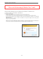
4. Please read the following if you are a Windows Vista, Windows 7, Windows 8 user. ...................................... 104
KW Watcher Operation Guide Book
0. Introduction
This manual is designed to provide instructions about the software for monitoring electrical power
(hereafter referred to as "KW Watcher") by obtaining log files from the Web Data Logger Unit (Hereafter
referred to as "DLU") , Data Logger Light (Hereafter referred to as "DLL") and FP7 and FP Web-Server.
*DLU, DLL, FP7, FP Web-Server are referred to as ‘connected device’.
[Caution]
1. This software is for monitoring current status effectively in order to achieve better energy efficiency.
No guarantee can be made for the displayed data because results could differ from the real figure due to
system error, measurement of the starting time, misalignment error of the measurement and the like
including this software.
2. This software is for internal use only to achieve better energy efficiency.
3. Refer to the each manual for usage of the connected devices.
● Operating system
OS: Microsoft® Windows XP
Microsoft® Windows Vista Business
Microsoft® Windows 7
Microsoft® Windows 8
● Windows, Excel are trademarks of Microsoft Corporation of the
United States in the United States and other nations.
● Compact Flash and CF are trademarks of SanDisk Corporation.
● Recommended specification
HDD
100MB or above
Recommended memory 98 series OS: 128MB or above, NT series OS: 256MB or above
Recommended CPU
Intel Celeron 700MHz or above (depending on OS)
Resolution
XGA (1024x768) [Caution] Excel is required to print Master Registration.
* If no graph is displayed, download Runtime (vbrun60sp6.exe) from Microsoft website.
● Notice before installation / Recommended usage
[System]
KW Watcher is designed for systems running "Web Data Logger Unit/Data Logger Light" and "EcoPOWER METER".
[No. of master registration].
Performance (display) speed may vary depending on the system environment or registry structure.
It is recommended to use this software with a registry number under 1,000.
[Overview of download]
KW Watcher downloads files with FTP (File Transfer Protocol) commands. As for the network
environment FTP commands can be used, check with your network administrator. Refer to "2.8 Option
setting" for details.
Setting file, Logging file
There is the case that a setting file or a logging file is erased by operation failure of a case and
install and uninstall of the software that a PC of the use was broken.
For an unexpected situation, I ask for backing up a setting file or a logging file.
- 1-
KW Watcher Operation Guide Book
[In case of using 64-bit PC]
It is impossible to use without Office 2010(64-bit).
In this case, follow one of the below.
1. Install Office 2010(64-bit)
2. Download “AccessDatabaseEngine_X64.exe” from the blow website and install it.
http://www.microsoft.com/ja-jp/download/details.aspx?id=13255
- 2-
KW Watcher Operation Guide Book
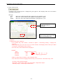
● Installation procedure and usage
With this software, operations are categorized into two major parts: “Settings” and “Data display”.
See Data display (2.9) if settings have been already configured.
(0)
Installation
(2.4)
Title setting
(2.5)
● Register DLU
(2.6)
● Register master
(2.7)
File setting
(2.8)
Option setting
(2.9)
Display data
“Settings”
Required in the first configuration or in case of modification
Marked setting by ● are required.
Others required in case of Modification in configuration.
“Display data” item
- 3-
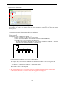
KW Watcher Operation Guide Book
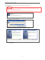
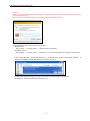
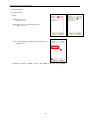
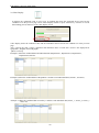
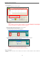
●Installation procedure (The following images are screenshots in Windows XP.)
Start setup.exe.
[Caution]
・To upgrade or change the version of KW Watcher, uninstall KW Watcher first and then reinstall it
Refer to the uninstall procedure for details.
・When you’d like to upgrade Ver.1.**, uninstall Ver.1.** before upgrade.
Select a language to use for installation.
After preparing for installation, KW Watcher Setup wizard will come up.
Click the "Next" button.
- 4-
KW Watcher Operation Guide Book
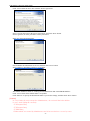
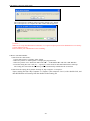
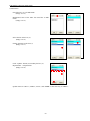
Click “Next” button to move on to software license agreement.
Select "I accept the terms in the license agreement", and click "Next" button.
Unless agreed to, no more procedures can be performed.
Input user name and organization.
Check whether the information is correct, and then click “Next” button.
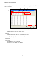
Select a folder to install the software in (if needed).
The default destination folder is “C:¥Program Files¥Panasonic-EW Control¥KW Watcher”.
Click “Next” button if the default folder is acceptable.
Click "Browse" to specify the destination folder if you need to change, and then click "Next" button.
[Caution]
In case of using by users except the Administrator, do not install the below folders.
It can’t work setting file correctly.
・「C:\Program Files」
・「C:\Program Data」
・「C:\Windows」
・Folders which are created by Administrator and it has restriction to access by users.
- 5-
KW Watcher Operation Guide Book
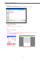
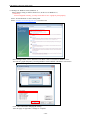
Click “Install” to continue installation.
[Caution!]
When users except the administrator install, it is required to input password of administrator’s account by
security function of OS.
Please confirm your administrator before installing. (Image of Windows 7)
- 6-
KW Watcher Operation Guide Book
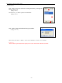
Click "Finish" after installation is complete.
- 7-
KW Watcher Operation Guide Book
● To uninstall the software
Finish KW Watcher before uninstall.
1) Use the installer package to uninstall the software
Start KW Watcher installer as before.
After preparing for installation, KW Watcher Setup wizard will come up.
Click the "Next" button.
Select "Remove", and click the "Next" button.
As the "Remove the Program" window appears, click "Remove".
The uninstallation process will begin.
- 8-
KW Watcher Operation Guide Book
[Caution!]
When users except the administrator uninstall, it is required to input password of administrator’s account by
security function of OS.
Please confirm your administrator before installing. (Image of Windows Vista)
2) To uninstall from the “Add or Remove Programs”
・Windows XP
Select “Start” -> “Control panel” -> “Add or Remove Programs”
・Windows Vista/7
Select “Start” -> “Control panel” -> “Programs” -> “Uninstall Programs” in “Programs and Features”
Select “Panasonic-EW Control KW Watcher” or “Panasonic-EW SUNX Control KW Watcher”, or
“Panasonic-ID SUNX Control KW Watcher” and click “Remove”.
A notification dialogue will pop up. Click “Yes” button to start to remove the program.
Clicking “No” button will abort the removal process.
- 9-
KW Watcher Operation Guide Book
The removal process window will pop up after clicking “Yes” button.
The removal process is complete after this window has disappeared.
[Caution!]
When users except the administrator uninstall, it is required to input password of administrator’s account by
security function of OS.
Please confirm your administrator before installing.
● How to start KW Watcher
1) Start from the “Start menu”
1. Open “Start menu” by clicking “Start” button.
2. Move the pointer to “All Programs” to display the program menu.
3. Move the pointer on to “Panasonic-EW Control ►” – “KW Watcher ►” and click “KW Watcher”.
4. Load the setting file from “File (F)” – “Open (O)” in the menu bar after KW Watcher has started up.
The setting file selected in the first start up will be automatically loaded after the second run.
2) Start from the setting file by double clicking on “My Computer” or “Explore”
Open a setting file from “My Computer” or “Explore” (file extension “.kww”) with a double click, and
then KW Watcher will start up from the double-clicked setting file.
- 10-
KW Watcher Operation Guide Book
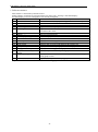
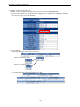
1. Software structure
This software is structured by functions below.
In this software, operations are categorized into two major parts: “Settings” and “Data display”.
See Data display (2.9) once settings have been already configured.
No.
Functions
Function Summary
1)
Menu
Provides file-related, display switching, and version-check operations.
2)
Title window
Indicates the main window of this software
3)
Title Setting
Enables title to be edited
4)
Master Registration
Registers masters to specify each DLU and Eco-POWER METER
5)
DLU Registration
Registers and controls numbers of connected DLUs, IP addresses and
accumulated file names
6)
File Setting
Sets destination folder to save files downloaded from DLU
7)
Option
Sets CO2 conversion rate
8)
Data display setting
Sets data display conditions
9)
Show Data
Displays collected data lists based on conditions set in 8)
10) Bar Graph
Displays data in a bar graph based on conditions set in 8)
11) Pie Graph
Displays tabulated data in a pie graph
12) Stack Graph
Displays data in a stack graph based on the graph in 10)
13) Compare Graph
Displays data in a compare graph based on the graph in 10)
14) Energy per unit Graph
Displays data in energy per unit graph
15) Temperature/Humidity/Trend Displays temperature/humidity/trend graph.
Graph
16) Graph capturing function
Displays saved screens in thumbnails up to 12 screens by quicksaving graph screens
17) Favorites function
Registers items specified to display graphs.
Explanation of each function is covered in the following pages.
- 11-
KW Watcher Operation Guide Book
2.Function details
2.1 Title bar
The title bar of KW Watcher shows the currently loaded setting.
An asterisk (*) will be added to the currently loaded setting if rewritten setting data is loaded, master registration is imported or the
setting file is modified after making any changes in the other settings.
(*) will disappear once the setting has been either overwritten or saved
as another setting.
2.2 Menu
It provides options for each related item to operate KW Watcher.
2.2.1 File
It enables the creating and edits setting files of KW Watcher.
The file extension of setting files is “.kww”
2.2.1.1 New
It enables the creation of new setting files.
Title setting, DLU registration, Master registration and File setting will be set as default.
2.2.1.2 Open
It opens the existing setting file.
2.2.1.3 Save
It overwrites currently loaded setting files.
2.2.1.4 Save as
It saves currently loaded setting files under different file names.
- 12-
KW Watcher Operation Guide Book
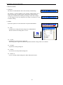
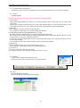
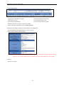
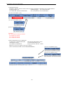
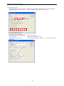
2.2.1.5 Load setting data
It loads other setting file data on to the currently loaded
setting files.
・ Title setting
・ DLU Registration
・ Master Registration
・ File Setting
・ Option Setting
Click “OK” button after checking the items to be loaded.
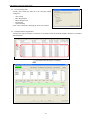
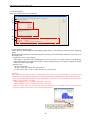
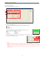
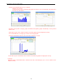
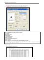
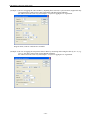
2.2.1.6 Import master registration
It enables the import of master record items in accordance with the attached template (default.csv) included
in KW Watcher.
Sample for importable format
Check data after the import is complete
- 13-
KW Watcher Operation Guide Book
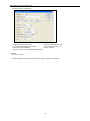
[Caution!]
‘*’ needs to be input in the first row of the 35th column (located in A35 if opened by Microsoft Excel) of the
CSV file. The import process may be cancelled due to a format error if no ‘*’ is included.
Make sure to check the import files before importing data.
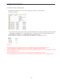
The import process may be cancelled and an error message pops up if any error is found.
Click “OK” button to see the import log. Try the import process again after correcting data according to the
log.
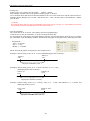
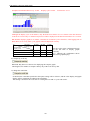
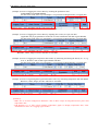
Example) Sample for import log
Example) The first row indicates the file name of the import source.
Row numbers and error details are specified from the second row.
<Common import error message>
● Format error Asterisk couldn’t be found
Check to see if an ’*’ is input in the first row of 35th column of import file.
● Some setting items are missing.
Data is missing between Item 1 and Item 5, among DLU No., or among Block No.
● Some setting items are overlapping.
There is more than one row in which the data of Item 5 are exactly the same.
Or, there is more than one row in which combinations of DLU No. and Block No. are exactly the same.
[Caution!]
Names in “TERM” (Item5) cannot be overlapped.
● Set name of items less than 50 characters.
● DLU No. is out of range. Set DLU No. between 1 and 9999.
● Number of DLU registration is more than 256.
● Block No. is out of range. Set Block No. between 1 and 300.
- 14-
KW Watcher Operation Guide Book
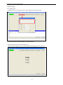
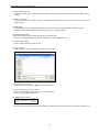
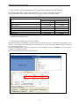
2.2.1.7 Export master registration
It enables the export of master registration of currently loaded setting file into CSV format as default.
2.2.1.8 Exit
Exit KW Watcher.
[Caution!] Please keep the followings for the temporary file of KW Watcher.
1) [.tmw] [.ldb]
When starting KW Watcher, the temporary files with setting file name [.tmw] and [.ldb] are made in the
same folder.
These 2 files are deleted automatically when exiting KW Watcher. However, when exiting forcibly by error,
they might not be deleted. It is no problem to delete these 2 files when not starting KW Watcher.
2) [DLU.log]
[DLU.log] file is the error file when connecting DLU.
It is no problem to delete this file when not starting KW Watcher.
3) CAPTURE¥(setting file name)folder¥00.bmp to 11.bmp
This folder and files are made when executing the graph capturing function.
The setting file name folder and files are deleted automatically when exiting KW Watcher. However, when
exiting forcibly by error, they might not be deleted.
If some files are saved in this folder, the files are deleted automatically when exiting KW Watcher. Do not
save files in this folder.
It is no problem to delete these folder and files when not starting KW Watcher.
4) [Import.log]
[Import.log] file is the log file to show master import error.
It is no problem to delete this file when not starting KW Watcher.
5) [Favorite.csv]
[Favorite.csv] file is the data file of favorites.
Do not delete this file as the information added to favorites is saved.
2.2.2 Setting
It shows all the settings and registration items.
Each item in the menu is exactly the same as the menu button.
2.2.3 Tool
Use it to change the language.
Restart KW Watcher after changing the language.
- 15-
KW Watcher Operation Guide Book
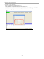
2.2.4 Help
It shows KW Watcher’s current version.
- 16-
KW Watcher Operation Guide Book
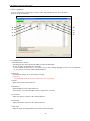
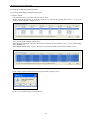
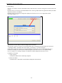
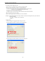
2.3 Title window
Image indicated below is the default main window of this software.
Image 2.2 Title (Main) Window
Selection box for setting files
Three different kinds of title can be shown.
No title can be shown as the default.
Selection box for setting files
If checked on “Display selection box for setting files on the title screen” in the option setting,
Folders in “save folder of the setting files displayed on the title screen” specified in the file setting will be
displayed in icon view.
Double-click any of folder icons in the selection box for the setting files to open the saved setting files.
[Caution!]
Save only ONE setting file in each folder displayed in icon view.
Folder icon will not open if there is more than one setting file or no setting file in a folder when doubleclicked.
- 17-
KW Watcher Operation Guide Book
2.3.1 Button menu
The explanation of the button menu on the main window is as follows:
Image 2.2.1 Buttons on the main window
Explanation of each button
1) “Show Data” button
Click to see the data display setting window.
(See 2.9 Data display setting)
2) “Title Setting” button
Click to see the title editing window.
(See 2.4 Title setting)
3) “DLU Registration” button
Click to see the DLU registration window.
(See 2.5 Register DLU)
[Caution!]
This button cannot be selected if "Disapprove to change DLU and master registration" is checked in
Option setting.
4) “Master Registration” button
Click to see the master registration window.
(See 2.6 Master registration)
[Caution!]
This button cannot be selected if "Disapprove to change DLU and master registration" is checked in
Option setting.
5) “File Setting” button
Click to see the file setting window.
(See 2.7 File setting)
6) “Option” button
Click to see the option setting window.
(See 2.8 Option setting)
7) “Manual download” button
It downloads manually.
8) “Download at once” button
It downloads csv files based on all the setting files stored in the folder specified in "File Setting".
- 18-
KW Watcher Operation Guide Book
2.4 Title setting
2.4.1 Change titles
It enables the user to register up to three titles displayed on the title window.
Click “OK” button to confirm changes to the title window.
Unnecessary titles can be deleted. (Image 2.3.2)
Titles set in this window are saved as the initial file and loaded in the next start-up.
Image 2.3.2 After title setting
- 19-
KW Watcher Operation Guide Book
2.4.2 Name for each item setting
Names of each item can be modified. (Image 2.3.3)
Click “OK” button to confirm after changing the names of Items 1 to 5.
Changes are reflected in the name of items shown on “Show Data”, “Master Registration” and the graph.
Items set here on the window are saved in the setting file and loaded in the next start-up.
In the default setting, they are “DIV”, “SCT”, “PRPS”, “FACI” and “TERM”.
Image 2.3.3 Setting screen
- 20-
KW Watcher Operation Guide Book
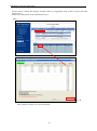
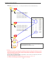
2.5 DLU registration
It sets to specify the connected device (DLU, DLL, FP7, FP Web-Server) to be tabulated.
It can be set up to 256 units.
DLU setting screen
1)
8)
2)
3)
7)
6)
5)
4)
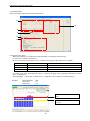
2.5.1 Setting items
1) Download check button
Checking this box skips checked IP addresses when downloading.
Be sure to make registrations after checking.
Use this button in such cases as "you want to reserve only settings although you have not set equipment."
or "you want to view a file without downloading it".
2) DLU No.
Set within the range of 1 to 9999 with no overlap.
[Caution!]
No tabulation result can be given if DLU No. isn’t set properly.
3) Name
Input name of the connected device.
4) IP address
Input IP address of the connected device.
From Version 1.10, same IP address can be registered in 2 or more.
5) User name
Input user name to connect to the connected device.
6) Password
Input password to connect to the connected device.
7) File name
Input file name of integrated data stored in the connected device.
- 21-
KW Watcher Operation Guide Book
8) Model Select
Select the connected device to download csv.files.
Items
Logger
FP7
FP Web-Server
Target
DLU or DLL
PLC FP7
FP Web-Server
[Caution!]
Refer to the each manual for the usage of each device.
Only the measured value measured by Eco-POWER METER is supported.
- 22-
KW Watcher Operation Guide Book
See file name in “Storage File Settings” window in DLU or "Logging file setup" in DLL to specify file name.
(Image 2.5.1.1)
Refer to the each manual for FP7 and FP Web-Server.
[DLU]
Image 2.5.1.1File name
Image 2.4.3 DLU registration screen
9)
Click “Register” button to save as the initial file.
- 23-
KW Watcher Operation Guide Book
[DLL]
Logging file setup
DLU registration screen
9)
9) “Return to the title window” button
・ Click “Return to the title window” button or press [F10] key to go back to the title window.
・ “title window” refers to the first main window when the software starts up.(See 2.3)
- 24-
KW Watcher Operation Guide Book
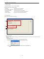
2.5.2 Input and edit setting items
1) How to input
Press Enter key or double-click the cell you wish to input data in order to
make it editable (Input mode) with a cursor ( | ) in the box.
You can also input directly.
Press Enter key or click other cells to confirm your input.
Press ESC key to cancel your input.
2) How to edit – Edit existing data
Press Enter key or double-click the cell you wish to input data into to make
the existing value highlighted in the box.
You can also modify the value by input directly into the box.
3) How to edit – Delete existing data
Press DELETE key to delete the data you wish to remove after moving to the cell.
Press DELETE key to delete a whole row after clicking row No. to select all (See image below).
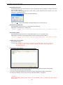
4) How to edit – Copy or move existing data
Press Ctrl + C to copy data you wish to copy after selecting cell or range.
Press Ctrl + X to cut data you wish to move after selecting cell or range.
Press Ctrl + V to paste data after moving to the row in which you wish to do so.
Copy and Move, and Paste are executed only in the relative columns.
For example, a copied name can only be pasted in the columns that have been used to store names.
Copy Sample: Copy from DLU name to file name in No.13 and paste them in No.14
↓
Move Sample: Cut data in No.13 and paste it in No.14
↓
- 25-
KW Watcher Operation Guide Book
2.5.3 Register and abort settings
Click the “Register” button to register settings.
The registration process window pops up after clicking the “Register” button. (See image below)
A window pops up to ask whether you wish to register or not if you move to other windows without register.
Setting details are registered if you click “Yes” here.
Setting details are aborted if you click “No”. And then the window disappears.
DLU registration continues after the window disappears if you click “Cancel”.
[Caution!] For using KW Watcher, set the configuration and logging file in DLU or DDL as below.
[DLU]
1) Select compact flash for storage place of logging file in “Main Unit Configuration Settings”.
(CF card is necessary to use KW Watcher.)
2) Logging File setup
File name
: Name it same as file name in DLU registration screen of KW Watcher.
(In case of setting by “DLU Setting Tool”, the file which name is [syunji] is created.)
Logging Trigger: 1hr.
Updating Trigger:
Every Day 00:00:00
No. of Records: 60000 (recommended)
No. of Generations: 60 (recommended)
* As for Logging Trigger and Updating Trigger, select from the items registered in Trigger Settings.
* To display data by 15 or 30 minutes, set the logging trigger to 15 or 30 minutes respectively.
- 26-
KW Watcher Operation Guide Book
3) Device Registration
Logging Type: Instantaneous Value
Data Format: DEC2W (No code)
Conversion: Convert
Conversion Parameter: 0.01
Unit: kWh (recommended)
Device Selection: DT100-1point
Block No.: Be sure to register consecutive number
(Device Selection, DT100 is for Eco-POWER METER.)
4) Storage File Settings for Various Action Settings in Configuration
Operation Without Enough Disk Space: Create a new file
Other settings should be initial settings.
[Caution!] When “Make [_MOD] file” and “Make [_POW] file” are unchecked, the data might be missing.
However, max version number will be exceeded, if it changes mode and turns on frequently.
5) Others
Be sure to set time.
- 27-
KW Watcher Operation Guide Book
[DLL]
Set the items in the setting software "Configurator DL" for DLL as below.
Configuration > Logging file setup
[Caution!]
・Always check "Make the destination folder name of logging file [CF].".
・Please warn him in there being a threat that logging data lack when I exclude a check to
"Make file with logging data in SRAM when power on.(_POW)" to "Make file with logging data in
SRAM when RUN to STOP.(_MOD)".
Other settings should be initial settings.
2) Logging file setup
Logging trigger No.: 15 min. cycle
Updating trigger: 0:00 of every day
Saved file number: 100
* As for Logging Trigger and Updating Trigger, select from the items registered in Trigger Settings.
* To display data by 15, 30 or 60 minutes, set the logging trigger to 15, 30 or 60 minutes respectively.
- 28-
KW Watcher Operation Guide Book
3) Logging device registration
Logging contents: Inst. Value
Data style: DEC2W(No code)
Convert when creating csv: Checked
Conversion parameter: 0.01
Unit: kWh (recommended)
Device: DT100
(Device: DT100 is for Eco-POWER METER.)
4) Others
Be sure to set time.
* For the details of each setting, refer to "Data Logger Light User's Manual".
- 29-
KW Watcher Operation Guide Book
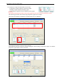
About Download error
When executing manual or automatic download, it may not be performed for any reason.
In such case, the master registration button turns red.
Moving to the DLU registration screen enables you to check on which connected device the error occurs.
(The connected device that the error occurs is highlighted in red.)
The display returns to the normal state under the following conditions.
- when measures against the error was taken and download was completed successfully after downloading
again
- when DLU registration was changed or updated
- when the setting file was switched
- when software was restarted
When the error occurs, a log file will be created in the following location.
・Windows XP
・Windows Vista/7
:C:¥Program Files¥Panasonic-EW Control¥KW Watcher¥DLU.log
:C:¥Users¥[User] ¥AppData¥Local¥VirtualStore¥Program Files¥
Panasonic-EW Control¥KW Watcher¥DLU.log
- 30-
KW Watcher Operation Guide Book
2.6 Mater registration
Master registration is needed in configuration to specify each connected device and Eco-POWER METER.
Changes (Add or Delete) are not reflected in the setting file immediately.
1)
2)
3)
4)
1) Print
・Click “Print” button to use the print function. (See 2.21 Print sample)
・It prints screens from the currently available printer. (See 2.20 Print function)
・Note that the print function does not work if the printer is not configured properly.
[Caution!] Excel is required to print the master registration.
2) Save
・Registration details for display condition are saved in CSV format.
3) Color clear (See 2.6.6)
・Clear all color settings for each item.
4) Return to the title window
・ Click “Return to the title window” or press the F10 key to go back to the title window.
- 31-
KW Watcher Operation Guide Book
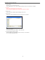
2.6.1 Register name
It registers names.
Image 2.6.1.1
①
1) Add
Image 2.6.1.2
②
Uncheck the box (1).
(Image 2.6.1.1)
Input names to be registered in the box (2).
(Image 2.6.1.2)
Image 2.6.1.3
Click “Add” button (2) to add to the list in the box (4).
(Image 2.6.1.3)
④
③
Add names in “SECT”, “PRPS”, “FACI”, and “TERM” in the same way as “DEPT”.
- 32-
KW Watcher Operation Guide Book
2) Edit names
Check the box (1) to be Edit mode.
(Image 2.6.1.4)
Image 2.6.1.4
①
Image 2.6.1.5
Image 2.6.1.6
Image 2.6.1.7
Background color of the name list turns blue in Edit
mode.
(Image 2.6.1.5)
Select the list in the box (2).
(Image 2.6.1.6)
③
Change the name in the box (3).
(Image 2.6.1.7)
②
Click “Update” button (4) to modify the box (2).
Department2 → Department3
(Image 2.6.1.8)
Image 2.6.1.8
②
④
Update names in “SECT”, “PRPS”, “FACI”, and “TERM” in the same way as “DEPT”.
- 33-
KW Watcher Operation Guide Book
3) Delete names
Click “Delete” button (5) to delete the existing name data by selecting from
the list in the box (2).
(Image 2.6.1.9)
Image 2.6.1.9
①
Check the box (1) is NOT required when DELETE.
(Image 2.6.1.9)
②
⑤
Click “Delete” button and confirm on the pop up window.
(Image 2.6.1.10)
Image 2.6.1.10
Delete names in “SECT”, “PRPS”, “FACI”, and “TERM” in the same way as “DEPT”.
[Caution!]
All the related registered data in the display items is also deleted when the name is deleted.
- 34-
KW Watcher Operation Guide Book
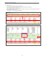
2.6.2 Select DLU and Block number
Select DLU and Block No. from the list.
1) Select DLU
Select from the <DLU> list.
Only registered DLU is displayed in the DLU list.
2) Select Block No.
Select from the <Block No.> list.
How to select Block No.
・ <Block No.> can be selected from the range of 1 to 250 in the list.
・ <Block No.> corresponds to data arrangement of logging file (csv file).
Block No.1
Block No.2 Block No.3
Block No.4・・・
Block No.
[Logging file (csv file)]
[Caution!]
Block No. is same as the registration number of logging device registration.
However, with the below case, the block No. is moved.
For DLU: Continuous block registration
For DLL: Register logging device from the top
- 35-
KW Watcher Operation Guide Book
[Caution!]
For DLL, it registers as to Image 2.6.2.2, when it saves with CSV file it push
into before position.
In case of Image 2.6.2.2, it registers No.3 without No.2, but block No. for KW
Watcher is ‘2’. If you need to avoid this, it registers to No.2 with dummy.
Image 2.6.2.1
Image 2.6.2.2
- 36-
KW Watcher Operation Guide Book
2.6.3 Display condition setting
Register each condition selected from the name registration list as a display condition.
・ If you select from DEPT list, name will be displayed in the green box of display condition setting
<Condition 1:DEPT>. (Image 2.6.3.1)
Image 2.6.3.1
・ Select the other lists for “SECT”, “PRPS”, “FACI”, “TERM”, “DLU”, and “Block No.” by the same way.
・ Click “Register” button after selecting each list to register Condition 1 to 5, DLU, and Block No.
(Image 2.6.3.2).
Image 2.6.3.2
・ Registration result can be reviewed on display condition registration history.
[Caution!]
Names in “TERM” (Item5) cannot be overlapped.
- 37-
KW Watcher Operation Guide Book
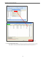
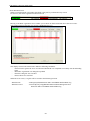
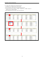
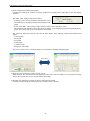
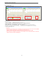
2.6.4 Display condition registration history
A list of registered display condition is displayed.
1) “Delete” button
Check delete boxes to select the item you wish to delete.
Double click the desired row or press the “SPACE” key after moving up and down with “↑”, “↓” keys to
check or uncheck the box. (Image 2.6.4.1)
Image 2.6.4.1
Also, you can check multiple rows at once.
Either drag down from the top row to the bottom row that you wish to delete or press “↓” key while holding
down “SHIFT” key.
Either RIGHT double-click or press “SPACE” key to check on all the selected rows. (Image 2.6.4.2)
Image 2.6.4.2
Click “Delete” button and confirm on the pop up window. (Image 2.6.4.3)
Image 2.6.4.3
Click “Yes” to confirm that you wish to delete.
- 38-
KW Watcher Operation Guide Book
If you wish to delete some records in the data, which is displayed in list view, the more data you select, the
longer it will take to delete, because it deletes one record after another. (Image 2.6.4.4)
Image 2.6.4.4
If you wish to delete the whole data, which is displayed in list view, no process window pops up like the
above example, because all the data is deleted at once.
All the data displayed in list view means all the registered data if no filter is applied, and all the data that
meets the filtering criteria is deleted at once if a filter is applied.
See “2.6.5 Apply filter in display item registration history”.
Window pops up when deletion is complete.
Image 2.6.4.5
- 39-
KW Watcher Operation Guide Book
2) “Edit” button
・ Click “Edit” button and it is indicated with yellow.
・ Select the display condition registration history and registered data is displayed.
・ Re-select display condition setting in 2.6.3.
・ Click “Update” button in the display condition setting to edit items on the display condition registration
history window. (Image 2.6.4.6)
・ See Image 2.6.4.7 to see the result after editing.
Image 2.6.4.6
Image 2.6.4.7
- 40-
KW Watcher Operation Guide Book
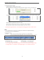
2.6.5 Apply filter in display item registration history
(1) Each item can be displayed with a filter applied.
(2) Click ▽button to select each item from the pull down menu.
(3) Apply the filter in this example to <DEPT> “Department1”, <PRPS> “Purpose1”.
Filtered items are indicated by ▼.
(4) You will return to▽ if you select “All” in the filtered list.
Image 2.6.5.1
(1)
(2)
(3)
(4)
- 41-
KW Watcher Operation Guide Book
2.6.6 Color setting for each item
It can designate color for each item.
It displays graphs with designated color for each item.
The color is set by random without the designation item when it displays graphs.
Up to 24-color can be registered for each item.
[How to register]
(1) Double-click the designated item.
(2) Color select window will appear and select
colors. (Image 2.6.6.1)
(3) After selecting color and click OK,
the back of the item will be changed with
selected color. (Image 2.6.6.2)
Image 2.6.6.1
[Caution!]
It is impossible to select colors when “Show
temperature/humidity/trend graph" is checked
on option setting.
Image 2.6.6.2
- 42-
KW Watcher Operation Guide Book
2.7 File setting
Sets the save location for files downloaded from connected device and for setting files selected on the title
screen.
Default of the save location of accumulated data files is the Log folder under the application folder (the folder
where this software is installed).
Default of the save location of setting files displayed on the title screen is set as Application folder.
(Next Page Image2.7.1)
Input directly or click “Refer” button to change the save location.
The structure of the save location of accumulated data files is decided based on the DLU No. selected in
“2.5 Register DLU” specified in this “File setting”. (See Image 2.7.2 in the next page)
Setting menu of the save location of setting files displayed on the title screen will be displayed only if
checked on “Display the selection box of the setting files on the title screen” in “2.8 Option setting”
See P.37 “Image 2.7.3 Settings examples of setting files folders displayed on the title screen”.
Available save location
(1) My Computer
Available in all directories inside My Computer.
(2) Network folders
Available in the connectable network folders displayed in My Network.
- 43-
KW Watcher Operation Guide Book
Image 2.7.1
Save location specified in File setting
ex.) C:¥Program Files¥Panasonic-EW Control¥KW Watcher¥Log
DLU0001
syunji (070901_010000_TRG).csv
syunji (070902_010000_TRG).csv
syunji(070903_010000_TRG).csv
:
syunji (070913_010000_TRG).csv
syunji (070914_010000_TRG).csv
syunji (070915_010000_TRG).csv
DLU setting
DLU0002
syunji (070901_010000_TRG).csv
syunji (070902_010000_TRG).csv
syunji (070903_010000_TRG).csv
:
syunji (070913_010000_TRG).csv
syunji (070914_010000_TRG).csv
syunji (070915_010000_TRG).csv
DLU0003
DLU9000
DLU9001
DLU No. folder is created according to DLU setting under the
folder specified in File setting.
Downloaded files are saved in this folder.
[Caution!]
Note that files accessed on a daily basis (recorded in 24 hours) can only process data for up to two
months due to the DLU setting, which sets the maximum number of generations of stored data as being
up to 60. Besides this, data covers the selected year from January to December if you select data on a
monthly basis in data display setting.
(In case of DLL, the maximum number of generations is 100. For files on a daily basis, data can be
processed for up to about three months.)
It is highly recommended to store downloaded CSV files in the PC for at least 1 year.
“0” is shown on the data display if no data exists (if files are missing).
- 44-
KW Watcher Operation Guide Book
Image 2.7.2 Settings examples of setting files folders displayed on the title screen
Folder specified in the file setting ex.) C:¥Program Files¥Panasonic-EW Control¥KW Watcher¥set
set
gas
GAS.kww
Energy per
unit
pcs.kww
Electrical
power
power.kww
Icons will be displayed
- 45-
KW Watcher Operation Guide Book
2.8 Option setting
Setup each setting in order to use KW Watcher.
Setup the blow items in option settings.
・download
:Set items related to download
・Screen display connection :Set items related to display
・Unit/Charge Setting
:Set items related to unit or charge
・Management
:Set items related to alarm threshold and keys
・Various functions
:Set items related to the other functions
2.8.1 Download
Setup each setting related to download.
1)
2)
3)
4)
1) Download setting
Either automatic download setting or manual download setting can be selected in the Download setting
options.
・ Download at start
It downloads the connected device’s stored data during start-up.
If you check it, the window shown below pops up during start-up.
Click “Yes” to start to download the stored data from the connected device.
- 46-
KW Watcher Operation Guide Book
・ Download at File open
Accumulated data in the connected device will be downloaded when opening the setting file checked
to activate this function.
Also, it will be downloaded when the system starts up when checked for this function even if not
checked on “Download at start”.
A pop-up window will appear before the download begins.
Click “Yes (Y)” to begin downloading accumulated data in the connected device.
・ Download at specified time
It downloads the connected device’s stored data at specified time.
Adjustment is available on a 5-minute basis.
[Caution!]If you’d like to update graph after downloading, check “Auto-update to display
graph”.
・ Download cyclically
It downloads the connected device’s stored data regularly in every specified period.
Adjustment is available on a 30-minute basis between 30 minutes and 180 minutes.
[Caution!]If you’d like to update graph after downloading, check “Auto-update to display
graph”.
・ “Manual download” button
It downloads manually.
[Caution!] It is highly recommended to download accumulated data from the connected
device when a file is newly opened, otherwise the latest data might not be
displayed correctly.
・ “Download at once” button
It downloads csv files based on all the setting files stored in the folder specified in "File Setting".
Only checked setting files will be downloaded.
A message "Download completion" will appear in Status if download completes successfully.
If it fails to download even one item, a message "Download failure" will appear.
[caution!]
When downloading during graph display the day (Month, Year), it update the graph display
automatically.
- 47-
KW Watcher Operation Guide Book
2) Source from Logger (DLU/DLL)
Sets the source of download in the connected device.
・CF/SD: Downloads data from a CF/SD card.
・Internal memory: Downloads data from the internal memory.
[Caution!]
・This item is not saved.
For usual operation, be sure to select "CF/SD". Select "Internal memory" for occasions such as
checking the connection. If selecting "Internal memory" for usual operation, all collected data will be
erased in case DLU becomes inoperable due to any troubles such as power failure.
・When the source is in DLL, this setting is not required.
3) Check data in Logger (DLU/DLL)
It doesn’t access the connected device during data processing if you uncheck this box.
[Caution!]
1. This item is not configured to be saved. It is automatically activated when KW Watcher starts up.
2. Generally, leave it checked under normal use conditions.
- 48-
KW Watcher Operation Guide Book
2.8.2 Screen display
Setup each setting related to screen display.
1)
2)
3)
4)
5)
6)
1) Auto-update to display graph
When checked, downloading data and updating graph display is automatically performed when displaying
graph.
Downloading and updating is automatically performed with specified download conditions at intervals set in
the display cycle.
[Applicable screens to auto-update]
Auto-update is performed when displaying the screen of current year, month and day of the following
graphs; Bar Graph, Pie Graph, Stack Graph, Compare Graph, Energy per unit Graph, Temperature Graph,
Humidity Graph, Trend Graph.
[Display cycle]
"60 min: On the hour"
"30 min: On the hour and 30 min. after the hour"
"15 min: On the hour, 15 min. , 30min. and 45 min. after the hour"
[Caution!]
Note that the latest data may not be downloaded if the clocks of the connected device and PC are not
synchronized, or depending on situations of communication and accumulating data of the connected device.
・There are the following restrictions on the auto-update to the next day, next month and next year on the
display cycle of 30 min. or 15 min..
When "Display Cycle" is "30min": Select the "1 day" tab.
When "Display Cycle" is "15min": Select the "1 day" tab.
* Unless the above tab is not selected, auto-update to the next day, next month and next year will not be
performed. ((Image below shows a case when selecting 15min.)
- 49-
KW Watcher Operation Guide Book
2) Delay time
Setting range: 0 to 5 minutes (by the minute) Default: 1 minute
This setting is available when "Auto-update to display graph" is checked.
Use it when the latest data cannot be downloaded due to the error of the clocks of PC and the connected device.
Example) When "Display cycle: 60 min." and "Delay time: 1 min.", the latest data is downloaded at 1 minute
after the hour.
[Caution!]
Note that the latest data may not be downloaded if the clocks are not correctly set, or depending on situations
of communication and accumulating data of the connected device.
3) Set the cutoff date
The cutoff date can be set for the value display and various graph displays.
Check the box of "Set the cutoff date". You can set a desired cutoff date.
For performing the value display and graph displays using the specified cutoff date, check the box of "Change
the cutoff date" on the data display window. If unchecked, the graphs are displayed in the following time frame.
・If unchecked:
Time: 0 to 23 hour
Day: 1 - 31 day
Month: 1 - 12 month
When checked, the graphs are displayed as the examples below.
Example 1) When setting "Time" to "8 - 7 hour" and displaying the data of January 1;
January 1
8:00
January 2
7:59
Displayed as the data of Jan. 1.
Example 2) When setting "Time" to "0 - 23 hour" and "Day" to "10 - 9 day",
and displaying the data of January;
February 29
January 10
23:59
0:00
Displayed as the data of January.
Example 3) When setting "Time" to "0 - 23 hour", "Day" to "1 - 31 day" and "Month" to "4 - 3 month", and
displaying the data of 2011.
April 1 2011
0:00
March 31 2012
23:59
Displayed as the data of the year 2011.
- 50-
KW Watcher Operation Guide Book
4) Show temperature/humidity/trend graph
Checking this enables the function to display temperature, humidity and trend graph on the data display
window.
Max./Min. value setting will be also available.
・Selecting "Auto" sets the maximum and minimum values
automatically for displaying temperature/humidity/trend
graph.
・Select "Max./Min. value setting" to input values in "Min. value" and "Max. value".
The minimum and maximum values specified here will be set for displaying temperature/humidity/trend
graph. The setting range is from -99999999 to 999999999.
The following functions cannot be used for the data display when showing temperature/humidity/trend
graph.
・Value Display
・Bar Graph
・Pie Graph
・Stack Graph
・Compare Graph
・Energy per unit Graph
You can use short-cut key to shift the displays of temperature, humidity and trend graph.
Ctrl+Alt+t
5) Show the select setting file window on title screen.
When checked, the selection box will be displayed on the title screen according to “save location for setting
files to show on the title screen” specified in the file setting.
6) Windows for indication of setting file names and setting file folder
Currently loaded setting file names and its save location can be checked.
- 51-
KW Watcher Operation Guide Book
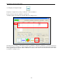
2.8.3 Unit/Charge Setting
Setup each setting related to unit and charge.
1)
2)
3)
1) Selection of the display units
Select units to display on the data display window on each data from below.
● kWh
● No unit
● Optional unit
Colors of the buttons for “Show Data” of the menu buttons for each
unit will be displayed as the image on the right.
kWh
: Green
No unit
: Light Blue
Optional unit
: Light Yellow
Preferred units including “CO2 rate” and “Charge display” can be specified if “Optional unit” is selected.
Units can be defined in up to 6 letters.
[Caution!]
・kWh unit display cannot be shown on each window if the “No unit” is selected.
・It is fixed ," Temperature Graph:℃"" Humidity graph:%" in the case of temperature / the humidity
graph.
・The indication unit becomes non-indication (effectively) when I chose an arbitrary unit by unit
indication choice.
- 52-
KW Watcher Operation Guide Book
2) CO2 rate
It changes CO2 conversion rate into preferred value.
Formula for leading total CO2 emission value displayed on each graph is as follows;
Total CO2 emission value = Total integrated electric power (or total integrated value) x CO2 conversion
rate / 1000. Total CO2 emission value can be indicated in less than 5 digits after decimal point, given no
input restriction on CO2 rate, so set the value up to less than 3 digits after decimal point for values over
0.001.
[Caution!]
・The indication unit becomes non-indication (effectively) when I chose an arbitrary unit by unit
indication choice.
3) Charge display
It toggles the converted charge display on/off on the graph display window.
Charge is calculated based on the charge rate set here in the case of displaying charge.
Time can be selected from the following three types.
・Uniformity:
・Daytime/Night:
Converts at the constant rate for 24 hours.
Converts at different rates for daytime and night.
Click "Time change" to set the hours of daytime. The rest of the hours will be
nighttime hours. (Default: Daytime: 6 to 22)
When daytime is set to "6 - 22", night is “22 – 6”.
・Summer/Other season: The period between July 1st and September 30th is summer. The other period
is other season. Time cannot be divided.
Example) July to September: JPY11
Others: JPY12
Cycle: 25th to 24th
June 25
June 30
July 24
Calculate with JPY12
Calculate with JPY 11
[Caution!]
・The indication unit becomes non-indication (effectively) when I chose an arbitrary unit
by unit indication choice.
- 53-
KW Watcher Operation Guide Book
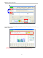
2.8.4 Management
Setup each setting related to alarm threshold and keys
1)
4)
2)
3)
5)
6)
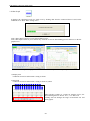
1) Integrated value alarm
When the graph data is exceeded the setting threshold, it can display alarm message.
In order to be available, check the box.
However, when the subtraction process is available, the integrated value alarm is not available.
Item
Alarm threshold
Alarm line 1
Alarm line 2
Contents
Input threshold as basis
Coefficient for alarm line 1
Coefficient for alarm line 2
Input range
0 to 99999999.99
1 ≧ Alarm line 1 value > Alarm line 2 value
Alarm line 1 > Alarm line 2 ≧ 0
According to the input alarm threshold value, it calculates the judge line by multiple coefficients for alarm
line 1 or alarm line 2.
Alarm threshold ×Alarm line 1 (Alarm line 2) = Alarm line value (round to two decimal places)
Example)
Alarm threshold
Alarm line 1
Alarm line 2
: 600
: 0.7
: 0.5
Alarm line 1 is shown at “420”.
(red)
Alarm line 2 is shown at “300”.
(yellow)
- 54-
KW Watcher Operation Guide Book
At option setting, it is value of display graph with 30 min. interval.
When the interval is 60 min., it is doubled. When the interval is 15 min., it is half value.
Example)
Display interval 60 min. : 840
Display interval 30 min. : 420
Display interval 15 min. : 210
Double
Half
When update data is exceeded alarm line 1 or alarm line 2, alarm message is blinking,
When exceeded alarm line 1
When exceeded alarm line 2
2) sound a buzzer
It sounds a buzzer when the value exceeds alarm line 1 or alarm line 2.
3) Communication time out
It set the communication time out period when it writes data to the designated registers.
When it is time out, it will retry once.
Range: 0 to 10 sec
4) DLU No., Register number, Port No.
It writes 0 or 1for the designated DLU/DLL when the value exceeds alarm line 1 or alarm line 2.
It is possible to give a notice via mail with mail sending function of DLU/DLL by using the value as a
trigger.
3 points for alarm line 1 and 3 points for alarm line 2 can be set.
When it exceeds line
When it is below the line
: It writes 1 for registers of the designated DLU/DLL.
: It writes 0 for registers of the designated DLU/DLL.
[Caution!]
KW Watcher is updated every 15 minutes (minimum). Note that when real time data is necessary.
It writes with MEWTOCOL command.
・DLU No.
Set DLU/DLL No. that is intended to be written.
When “0” or unregistered number is set, it doesn’t write.
・Register number
Set register number that is intended to be written.
Refer to the manual of DLU/DLL for the data register.
[Caution!]
Set the vacant register for the writing register.
If using register is set, it doesn’t work correctly.
- 55-
KW Watcher Operation Guide Book
・Port No.
Set the connection port number of DLU/DLL.
●Conditions to display the alarm message
When it satisfies the following conditions with check the box of “Integrated alarm” at option setting.
・Integrated value, that is updated with auto-update, is exceeded the alarm line.
・When you select time data for data kind and it displays the below graph.
Display graph, Stack Graph, Compare Graph (exclude when subtraction)
●Conditions to stop the alarm message
・When “Alarm clear” is clicked. (It displays only when you check the box of “Integrated alarm”.
・When you change display date with arrow buttons.
・When you shift to another menu.
・When you click “OK” with displaying graph regardless the setting at option setting.
・When you download data.
5) Management line
Blue line is displayed for graph of the max. electrical power.
It doesn’t write for external device. (It is only your guide.)
6) Make setting change impossible
This is the function to prevent menu button setting change not to intend.
・Password Select ‘Yes’, it is necessary to input password to change settings.
Only when the password is correct, it can be changed.
Select ‘No’, menu buttons are unable and it is impossible to change settings.
Initial: No
Only when you select ‘Yes’, set password within 8-letter
[Caution!]
Be cautions to the setting of password. The password setting is intended to prevent an unprepared setting
change, but a setting change is not possible when you forget a password.
・Password (reenter)
Input password that is set at the above.
・Select items to protect
Select from ‘Title Setting’, ‘DLU Registration’, ‘Master Registration’ ‘File Setting’ that
you protect from change settings.
Initial: No check
However, when ‘Disapprove to change DLU and master registration’ is checked
with ver.230 or before ‘DLU Registration’ and ‘Master Registration’ are checked.
When you select ‘Yes’ for password, it checks box of ‘Option’ automatically.
If you don’t use this function, select ‘No’ for password and not check all boxes for ‘Select time to
protect’.
- 56-
KW Watcher Operation Guide Book
【Download overview of KW Watcher】
KW Watcher downloads data with FTP (File Transfer Protocol) commands.
LAN
Connected
device
Downloads with FPT command
(Logging files)
PC
(KW Watcher)
* Download may not be performed because of security software (such as firewall).
In such case, check with your network administrator if FTP commands can be used.
- 57-
KW Watcher Operation Guide Book
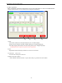
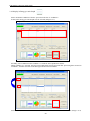
2.9 Show Data setting
Set condition for show data.
Image 2.9.1 Data display setting screen
When displaying temperature/humidity/trend graph
Operation flow
(1)Select Condition 1→ (2)Subtraction (Check as necessary.) →
(3)Select Condition 2・Subtraction (Check as necessary.) → (4)Select Data kind →
(5)Select Maximum value of graph (Set to "Manual" as necessary) →
(6)Select Time data → (7)Select Display cycle → (8)Compare by week day (Check as necessary) →
(9)Change the cutoff date (Check as necessary) → (10)Maximum value of graph (Check as necessary)
(11)Select graph display icon
[Caution!]
1. Values after the decimal point are not displayed if the integrated electrical power value of Eco-POWER
METER, includes a decimal point, exceeds 8 digits (Example:999999.99).
Values after the decimal point are displayed if the value goes down to less than 8 digits.
2. If the setting file is modified or the master record is imported, click “Show Data” button to refresh this
window since previous data is still displayed.
- 58-
KW Watcher Operation Guide Book
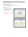
1) Display item
Multiple objects can be selected from display item 1 to 5 in the list box.
In the case of Image 2.9.2, if “Department 2” and “Department 4” of Item 1<DEPT> in condition 1 are
selected, <SECT> under the selected <DEPT> is displayed in Item 2. (Image 2.9.3)
Image 2.9.2
Image 2.9.3
2) Data kind
Select by checking the item. (Image 2.9.4)
Image 2.9.4
3) Time data
According to the kind selected in 2), the specifiable range varies.
When select Day data, time data consists of Year and Month.
Image 2.9.5
[Caution!]
Specifiable Year is for past 12 years, including this
year.
- 59-
KW Watcher Operation Guide Book
4) Maximum value of graph
・ Auto
・ Manual
Select from above. (Image 2.9.6)
You can directly input the maximum value in the box if you select manual.
Image 2.9.6
[Caution!]
Select condition 2 to display temperature graph and set the maximum value of electric power.
This setting is not available when displaying temperature graph.
Set the maximum and minimum values for temperature graph in "Show temperature/humidity/trend graph"
of the option setting window.
It is saved with setting file.
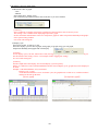
5) Display cycle
Select from 60 min, 30 min or 15 min.
Select the display cycle for the bar graph, stack graph, pie graph, energy per unit graph,
temperature/humidity/trend graph and value display.
[Caution!]
To use display cycles, 60 min, 30min and 15 min, the logging trigger of DLU (DLL) should be correctly set.
For the details of the setting, refer to "3.2 Example of DLU logging file setting".
It is saved with setting file.
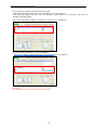
[Caution!]
For Bar Graph and Value Display, the selected display cycle has priority.
If there is a difference between downloaded data and the selected display cycle, graphs may not be displayed
in detail.
Example 1) Downloaded data: Every 60 minutes
Display cycle: 15 min.
As the downloaded data is not in 15-minute cycle, the graph shows no data at 15, 30 and 45 minutes
and shows the data on the hour.
【Power graph】
【Temperature graph】
- 60-
KW Watcher Operation Guide Book
Example 2) Downloaded data: Every 15 minutes
Display cycle: 60 min.
As the necessary data for displaying the graph in 60-minute cycle is downloaded, the graph shows
the data every 60 minutes.
【Power graph】
【Temperature graph】
Checking "Auto-update to display graph" downloads and updates graphs automatically in the specified
display cycle.
If the data in cycles of 60, 30 and 15 minutes are mixed, graphs cannot be displayed correctly.
It is recommended to use a single type of time axis for logging data.
Example) Graph that the data in cycles of 60 and 15 minutes are mixed
As the data in cycles of 60 minutes and 15 minutes are mixed, the graph is not displayed correctly.
[Caution!]
When the time of downloaded data is different from the selected display cycle, see the contents of the
display carefully.
- 61-
KW Watcher Operation Guide Book
Example) Downloaded data: Every 15 min. Display cycle: 60 min. Current time: 10:15
Although the display cycle is 60 minutes, only the data from 10:00 to 10:15 is shown as the data between
10:00 to 10:59 since only 15 minutes has passed. It will be displayed as the data for 60 minutes at 11 o'clock.
KW Watcher displays graphs in 15-minute, 30-minute or 60-minute cycles. Therefore, if the logging time of
DLU (DLL) is set to any other cycle, graphs cannot be displayed correctly.
60 min
30 min
15 min
60 min
30 min
○
×
○
○
○
○
15 min
×
×
○
KW Watcher
Display cycle
DLU/DLL
Logging cycle
Set the cycles in the combination shown
in the left table to display graphs
correctly.
("○” indicates the combination shows
the correct graph display.)
6) Compare by week day
Data kind: Day data. It is effective for displaying the compare graph.
Checking this box enables to compare data by day of the week not by date.
7) Change the cutoff date
If checked, the cutoff date specified in the option setting will be effective, and the value display and graph
display will be performed according to the cutoff date.
This setting is useful for the cases such as "closing date on 10th" or "year-end cutoff".
- 62-
KW Watcher Operation Guide Book
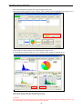
8)Max. electric power
If checked, max. electrical power is displayed by plot graph or value display with unit of 30 minutes
according to the data type.
Data type:
Time
Day
Month
: Max value of the designated date is displayed with 30 minutes cycle.
: Take max. value in the day, and it displays a plot graph for 1 month.
: Take max value in the month, and it displays a plot graph for 1 year.
Max. electrical power value
and the date, time are
displayed.
It shows the max electrical
power (upper) and average value
(lower) by changing color.
[Caution!]
It displays the below conditions.
・It is available only when “kWh” is selected at “Option -> Unit/Charge Setting -> Display unit
selection”.
・When collection cycle of csv file is ser to 15 min or 30min, it will display with 30 min cycle. When
it is 60 min, it will display for the reference.
・Twice the value of the measurement is displayed.
Example)
Time
00:00:00
00:30:00
01:00:00
Integrated electrical power
100
120-100 = 20 × 2 = 40
120
It displays graph with 40.
125
・When it is data of day or month, it will average the value.
It uses the value of 0 for averaging; therefore it may reverse the max. value and average value.
・It doesn’t select the below graphs.
“Pie Graph” “Stack Graph” “Energy per unit Graph” “Temperature Graph”
“Humidity Graph” “Trend Graph” “Subtraction”
- 63-
KW Watcher Operation Guide Book
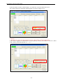
9) Subtraction 1/Subtraction 2
Checking this box performs the subtraction procedure, and performs value and graph displays.
For example, it is useful if you want to check the values calculated by subtracting any items from master
electric power.
Subtraction 1: Performs subtraction procedure for Condition 1.
Subtraction 2: Performs subtraction procedure for Condition 2.
【How to select】
Example) (1) Check "Subtraction 1" button.(A)
(2) Check "Condition 1" and select the source items.
(3) Check "Subtract condition 1" and select the items to be subtracted.(BCDE)
(4) Press the icons of "Value Display" and "Bar Graph".
The value calculated by subtracting the items selected in "Subtract condition 2" from the
items selected in "Subtract condition 1" is displayed. (F)
A
B
C
D
E
F
I demand F of non-measurement.
* Follow the same procedure if you want to set the condition 2.
To compare data, select items in Condition 2 and Subtraction condition 2 after selecting items in
Condition 1 and Subtraction condition 1 as below.
"Condition 1" - "Subtraction condition 1" = Subtraction result 1
"Condition 2" - "Subtraction condition 2" = Subtraction result 2
The results 1 and 2 can be compared.
*・The subtraction procedure is not available for the pie graph, stack graph and energy per unit graph.
・If the result of subtraction is a negative value, the bar graph is not displayed.
・Uncheck this function not to perform the subtraction procedure.
- 64-
KW Watcher Operation Guide Book
10) “Value Display” icon (Shortcut key: Ctrl+D)
It provides preview of the calculated result (See 2.10).
11) “Bar Graph” icon (Shortcut key: Ctrl+B)
It provides the calculated result in a graph (See 2.11).
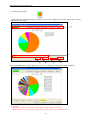
12) “Pie Graph” icon
It provides the calculated result in a pie graph (See 2.12).
13) “Stack Graph” icon
It provides the calculated result in a stack graph (See 2.13).
14) “Compare Graph” icon
It provides the calculated result in a compare graph (See 2.14).
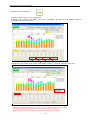
15) “Energy per unit Graph” icon
It provides data in energy per unit graph (See 2.15).
16) "Temperature Graph", "Humidity Graph" and
"Trend Graph" icons
It provides data in temperature, humidity and trend graphs.
(See 2.16).
- 65-
KW Watcher Operation Guide Book
[Caution!]
・As to missing data
When it displays graphs, the below message may be given.
This message will be given if some data are missing during the displayed period.
For example, the below conditions are considered that some data are missing.
・Communication error caused not to collect the measured value
・It set unconnected number with collection setup of DLU/DLL
・No data in the logging file.
- 66-
KW Watcher Operation Guide Book
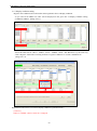
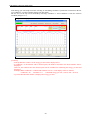
2.9 Value Display
It displays the calculated result in a list view by loading data from the connected device based on the
condition set in the previous page. Click "Value Display" button or press shortcut key "Ctrl+D" to execute
data loading process and move to the value display screen.
Image 2.10.1
Value display shows the combined value and the individual values based on the condition set in the previous
page.
Also, it shows the total, average, maximum and minimum values of each item. (Total is not displayed for
temperature, humidity and trend graph.)
【How to select】
Example 1) Show the combined data and individual data (Department 1, Department 2, Department 3,
Department4) in Item 1.
Example 2) Show the combined data of Department 1 and the serial individual data (Section 1, Section 2).
Example 3) Show the combined data of Facility 1 and the serial individual data (Term1_1, Term1_2, Term1_3
and so on).
- 67-
KW Watcher Operation Guide Book
When selecting up to condition 2 in "Show Data" and performing the value display, the total, average, maximum,
minimum values of condition 2 and the ratio to the total of condition 1 are displayed beneath the result of the
items set in condition 1.
1)
2)
3)
Image 2.10.2
7)
4)
1) Display item
Condition selected in “Show Data” setting is displayed.
2) Data kind
Condition selected in the “Show Data” setting is displayed in yellow.
3) Total integrated power [kWh] / Total CO2 exhaust [t-CO2]
It displays total integrated power and total CO2 exhaust.
4) Print screen
Click to print screen.
5) Save screen
Save the displayed graph as a image file.
You can select 3 types “BMP”, “JPG” and “PNG”.
- 68-
5)
6)
KW Watcher Operation Guide Book
6) Save CSV
Collection result is saved with csv file.
Dialogue to specify save location is displayed after clicking “Save CSV” button.
Image 2.10.3
Specify the save location.
Data is saved in CSV format.
[Caution!]
Line feeds are inserted after every 255 items.
7) File
Collection result is printed.
[Caution!]
In the value display, “Print preview(V)” and “Print(P)” from File(F) in task bar are selected.
You can check print image by selecting print preview.
It is available only value display.
[Print preview window]
- 69-
KW Watcher Operation Guide Book
2.10 Bar Graph
It displays the calculated result in a graph view by loading data from the connected device based on the
condition set in "Show Data" setting in 2.9.
Image 2.11.1
Click “Show Data” button to execute data loading process.
Click "Bar Graph" button or press shortcut key "Ctrl+B" to execute data loading process and move to the bar
graph screen.
Image 2.11.2
[Bar Graph]
[max. electric power]
1) Display item
Condition selected in “Show Data” setting is shown.
2) Data kind
Condition selected in “Show Data” setting is shown in yellow.
When selecting "30min" or "15min" for "Display Cycle", the
tabs indicating time are shown. "0-6", "3-9" and so on.
Clicking each tab changes the range of horizontal axis and
shows graphs.
- 70-
KW Watcher Operation Guide Book
3) Total integrated power
It shows the total value of tabulated integrated EP during the period specified by the “Show Data” setting
window.
4) Total CO2 exhaust
It shows the total CO2 exhaust value by calculating total integrated power and conversion rate factor in
Option setting.
5) Total charge
It calculates electricity charge based on the total integrated power and charge rate in Option setting.
It displays when charge display option is selected “Yes” in Option setting.
6) Peak integrated value
It shows the peak integrated value during the specified period.
A mark "+" is displayed under the graph to indicate the peak integrated value.
7) “Print screen” button
Click to print a hardcopy of the screen.
8) “Save” button
Click this button to pop up dialogue to specify save location.
Image 2.11.3
Specify the save location.
You can select file type from “BMP”, “JPG” and “PNG”.
9) “Screen temporary memory” button
Click to save hardcopy of the screen up to 12 screenshots.
See 2.18 Graph capturing function.
10) "Change Date" button
Press the arrow buttons located next to the date to change the date to the previous or next day (month, year).
- 71-
KW Watcher Operation Guide Book
2.11 Display in pie graph
Calculated result in multiple display conditions based on the conditions specified in “Show data” setting is
displayed in a pie graph.
Image 2.12.1 Pie graph with the names of DEPT
1)
2)
3)
4)
5)
6)
Click “By TERM” button or press shortcut key “Ctrl+5” to display pie chart with the name of TERM.
Image 2.12.2 Pie chart with the names of TERM
[Caution!]
Result shows only top 20 items and others if their series numbers exceed 20.
Display position varies depending on the number of characters of each registered name.
- 72-
KW Watcher Operation Guide Book
1) Title input
Title can be directly modified.
You can input up to 50 letters but it doesn’t be saved.
2) Select unit of total
These select buttons are indicated with the name of item setting set in title setting.
3) Color setting
Designate colors for the displayed items.
After designating the color, it will be displayed with same colors even if the date is changed.
[Caution!]
Other colors of the displayed can be designated.
You can check the designated colors on the master registration window.
4) Print screen
Click “Print screen” button to print a hardcopy of the screen.
5) Save screen
Click “Save” button and dialogue pops up to specify the save location.
Image 2.12.3
Specify save location.
You can select file type from “BMP”, “JPG” and “PNG”.
6) “Screen temporary memory” button
Click the button to save the hardcopy of the screen up to 12 screenshots.
See 2.18 Graph capturing function
- 73-
KW Watcher Operation Guide Book
2.12 Display in a Stack Graph
It displays “Bar Graph” (2.11) in a stack graph.
It displays in five categories “By DEPT”, “By SECT”, “By PRPS”, “By FACI” and “By TERM”, which are
switchable with unit of total button.
Image 2.13.1 Stack Graph
3)
1)
4)
2)
Click the list at the bottom of the window, and it displays details in each item at the time at the right.
Image 2.13.2 Build-up graph
[Caution!]
Total charge is displayed only if you select “Yes” for Charge display in option setting.
It displays the top 20 items and others if the number of items exceeds 20.
Display position varies depending on the number of letters for each name.
- 74-
KW Watcher Operation Guide Book
1) Color setting
Designate colors for the displayed items.
After designating the color, it will be displayed with same colors even if the date is changed.
[Caution!]
Other colors of the displayed can be designated.
You can check the designated colors on the master registration window.
2) Print screen
Click “Print screen” button to print a hardcopy of the screen.
3) Save screen
Click “Save” button and dialogue pops up to specify the save location.
Image 2.13.3
Specify save location.
You can select file type from “BMP”, “JPG” and “PNG”.
4) “Screen temporary memory” button
Click the button to save the hardcopy of the screen up to 12 screenshots.
See 2.18 Graph capturing function
- 75-
KW Watcher Operation Guide Book
2.13 Display in Compare Graph
It displays a comparison by setting “Condition 1” and “Condition 2”.
Firstly, select the items for condition 1 from the list.
“Compare graph” icon cannot be selected at this time. (Image 2.14.1)
Image 2.14.1 Select condition 1
Secondly, select condition 2 with check to select for condition 1. When the condition 2 is selected it processes
the selected data for condition 1. And “Compare graph” icon is activated and the data kind and the maximum
value of graph cannot be selected. When condition 2 is clicked, select status of each item shows the same status
as condition 1. (Image 2.14.2)
- 76-
KW Watcher Operation Guide Book
Image 2.14.2 Status when the condition 2 is selected
Compare graph is displayed by clicking “Compare Graph” icon after selecting condition 2 from the list.
List view at the top of the window can be switched with “Condition 1” and “Condition 2” by using “Select
condition”. (Image 2.14.3)
Image 2.14.3 Display selected condition in the condition 2
[Caution!]
Total charge is displayed only if you select “Yes” for Charge display in option setting.
- 77-
KW Watcher Operation Guide Book
2.14 Display in Energy per unit Graph
Select calculation condition of electric power from the list of “condition 1”.
At this point, Energy per unit Graph can’t be selected (Image 2.15.1).
Image 2.15.1 Selection of condition 1
Secondly, select condition 2 after condition 1 is checked. Select production volume.
When condition 2 is selected, the basic unit graph button will be activated after processing data selected in
condition 1, and then selection of the data type will become unavailable.
Image 2.15.2 Status of when condition 2 is selected
Selection status of each item when condition 2 is clicked will be the same as that of condition1 (Image 2.15.2)
- 78-
KW Watcher Operation Guide Book
Click Energy per unit Graph icon after selecting its calculating condition of production volume from the list
of “Condition 2” in order to display Energy per unit Graph.
The list view on the top can be switched by choosing “Condition 1” and “Condition 2” from the selection
condition (Image 2.15.3).
Image 2.15.3 Display the selection condition of “Condition 2”
[Caution !]
・If the production volume is 0, the energy per unit will be displayed as 0.
・If condition 2 is the number with a decimal point, the number rounded to the whole number will be
displayed.
However, the numbers after the decimal point will be included for calculating the energy per unit and
displayed.
Example) When condition 1 is 20kwh and condition 2 is 10.5, each display will be as follows;
Condition 1: 20 Condition 2: 11 Calculated energy per unit: 1.904 (1.904 = 20/10.5)
・Up to the third decimal number is displayed for energy per unit.
- 79-
KW Watcher Operation Guide Book
2.15 Display in Temperature/Humidity/Trend Graph
・Temperature Graph: It displays temperature graph.
・Humidity Graph: It displays humidity graph.
・Trend Graph: It displays selected conditions in line graph.
[Caution!]
The function and setting procedure of these three graphs are the same except for the display of units.
The following procedure is described using temperature graph as an example.
Select the item to display Temperature Graph from the list of "Condition 1".
Selection of condition 1
A maximum of 20 items (in Item 5) can be selected.
If more than 20 items are selected, a message will appear when clicking "Temperature Graph" icon and the
temperature graph display will be cancelled.
Status of when more than 20 items are selected
- 80-
KW Watcher Operation Guide Book
It displays the temperature graph calculated under different display conditions based on the condition set in
"Show Data".
Temperature Graph
[No missing data]
[With data missing]
[Caution!]
When the data from DLL are missing ('-' in csv file), it doesn’t show graph for missing data time.
1) Display condition
The condition selected in the data display setting is displayed.
2) Data kind
The condition selected in the data display setting is displayed in yellow.
- 81-
KW Watcher Operation Guide Book
3) Series data display
Clicking a series color at the bottom of the graph displays its breakdown in the explanatory area on the
right side of the graph.
[Caution!]
・Series data display is available only for time data. Series colors are not displayed at the bottom of the
graphs for month and day data. When there is no series data during the period, it displays by ‘-‘.
・When setting 15 min or 30 min for display cycle, all of data cannot be displayed all at once.
Change to the display at the time you want to check.
- 82-
KW Watcher Operation Guide Book
2.16 Temperature (Humidity/Trend) and Power Graphs
Temperature (humidity/trend) and power graph display can be superimposed.
(The following example shows the case of temperature graph, however, the procedure is the same for
humidity and trend graphs.)
(1) Select the calculating condition of temperature from the list of "Condition 1".
(2) After checking "Condition 1", select "Condition 2".
Select the calculating condition of electric power from the list of "Condition 2".
[Caution!]
For "Condition 2", be sure to select electric power data.
- 83-
KW Watcher Operation Guide Book
(3) Clicking "Temperature Graph" button after selecting "Condition 2" displays temperature and
electric power data together.
[Caution!]
・When performing auto-update of graphs, note that the graphs may not be updated simultaneously if DLU
(DLL) collects temperature (humidity/trend) data and electric power data at different times.
Setting "Delay time" in the option setting (see "12) Delay time" in "2.8 Option setting") enables to correct
the time error (up to 5 minutes).
・This setting is not necessary if you do not display temperature and power graphs together.
・The unit in the list and that shown in the right upper part of the graph is always kwh. As they cannot be
changed or hidden, be sure to select power data in "Condition 2".
【For using updated KW Watcher】
If you update KW Watcher for use, you should insert the master registration information of electric power
data into the master registration of temperature (humidity/trend) data. (The following explanation is the case
of temperature data.)
(1) Export the master registration of temperature data (see 2.1.1.7).
(2) Export the master registration of electric power data (see 2.1.1.7).
(3) Insert the master registration of power data after the exported master registration of temperature data.
* The contents of Item 5 cannot be overlapped (see page 10).
Insert the master registration of power data
after conditions of temperature.
(4) Import the edited master registration file of temperature data.
(5) If the inserted power data is not registered in DLU, make the DLU registration (see 2.5).
(6) After making those settings, select condition 1 and condition 2. Click "Temperature Graph" button to
show the superimposed display of the two graphs.
- 84-
KW Watcher Operation Guide Book
2.17 Graph capturing function
It can save graphs up to 12 by clicking “Screen temporary memory” button when each graph is displayed.
(Image 2.18.2)
Image 2.18.1 Save screenshots
Once the button is clicked, number in the box of Display the memorized screen indicated with yellow.
Image 2.18.2 After capturing graph screen once
- 85-
KW Watcher Operation Guide Book
This is the explanation to display four captured graphs side by side.
Firstly, after capturing graphs 4 times, click the yellow number button to highlight in red. (Image 2.18.3)
Image 2.18.3 After capturing graph screens 4 times
Click “Display” button to display the captured graphs. (Image 2.18.4)
It can display the captured graphs up to 12 by clicking yellow number to highlight in red.
Image 2.18.4 Display sample of 4 captured graphs
Click “Print screen” button to print the current screen.
Click “Save” button to save the current screen as image.
[Caution!]
The display of the memorized screen may be different from the actual display depending on the PC you
use. For example, a line is disappeared or letters are illegible.
- 86-
KW Watcher Operation Guide Book
Select the number to make it red like Image 2.18.5 and click “Clear the memorized screen”.
The yellow button turns off and the captured graphs are cleared. (Image 2.18.6)
Image 2.18.5 Prepare to delete captured graphs
[Caution!]
Note that click “Clear all of the memorized screen” makes all the captured graphs delete.
In this status, if graphs are captured from “Screen temporary memory”, the number in the box is filled
with a yellow in the following order: (1) → (3) ・・・ .
Image 2.18.6 Delete captured graphs
- 87-
KW Watcher Operation Guide Book
2.18 Favorites function
The settings of "Display item", "Data kind", "Maximum value of graph", "Time data", "Display cycle" and
"Compare by week day" can be registered. The registered settings can be retrieved from the next operation.
Registrable items
Click "Favorites" button to register, select or delete items.
1)
2)
3)
1) Register
Registers specified selected conditions.
Registrable items: Display item, Data kind, Maximum value of graph, Time data, Display cycle,
Compare by week day
Maximum number of registrations: 10
Maximum characters per title: 20 characters (one-byte) (It cannot be registered when no setting is made.)
Two “favorites” screens are available, which are for "Power graph" and
"Temperature/Humidity/Trend graph".
[Caution!]
Favorites cannot be registered for each setting file. Therefore, note that if favorite data registered in a
setting file is selected in another setting file (e.g. registering data in power graph and reading in energy
per unit graph), an error may occur as the conditions of the master registrations differ.
2) Select
Calls up registered conditions.
3) Delete
Deletes registered conditions.
- 88-
KW Watcher Operation Guide Book
[How to register]
(1) Input the conditions you want to register.
[Caution!]
When "Condition 2" needs to be input for graphs such as compare graph and energy per unit graph,
click "Favorites" button after inputting "Condition 2". Note that if "Condition 1" is checked again
after that, the conditions of "Condition 2" will not be registered.
(2) Press "Favorites" button to open "Favorites setup" window.
(3) Check the number you want to register.
The checked number and name will be highlighted.
(4) Input the name and press "Register" button. A confirmation message will appear.
Press "OK" button to complete the registration.
[Caution!]
・Favorites cannot be registered unless the name is input.
・The same name can be used for more than one favorite data.
[How to select/delete]
Check the number you want to select or delete. Press "Select" or "Delete" button to select or delete the
favorites.
- 89-
KW Watcher Operation Guide Book
2.19 Print function
Click “Print screen” button to print screens in each display window. (Image 2.20.1)
Image 2.20.1
Click “Print screen” button and “Printer setting and print” window pops up. (Image 2.20.2)
Image 2.20.2 Printer setting and print window
Click “Print” button to print by the currently selected printer.
Printer setting window pops up when “Property” button is clicked. (Image 2.20.3)
- 90-
KW Watcher Operation Guide Book
The window below pops up, and it can set the print setting for printers.
[Caution!]
Note that type of setting window varies depending on a printer.
Image 2.20.3 Print setting window by clicking “Property” button
[Caution!] Property of printer setting and print set by KW Watcher
Only 7 setting items can be edited in property as follows:
・Type of paper
・Paper feeding option
・Printing quality
・Color / Black and white
・Double face printing
・Page orientation (Horizontal/Vertical)
・Number of copies
Setting in the property above becomes active while KW Watcher is running.
However, setting might need to be changing each time depending on a printer type.
To activate other property settings, the print setting of the default printer needs to be configured beforehand in
the “Printer and Fax” option in the Start menu.
2.20 Print sample
Below is the sample. (Image 2.21.1)
Image 2.21.1 “Print” sample of master registration
- 91-
KW Watcher Operation Guide Book
3. Useful tips about collecting data
If the data for a given time in a CSV file is missing (0 or minus), it works as below.
Example) 15 minutes
1) For the data of 0:45:00, it needs data of 1:00:00. But the data of 1:00:00 is missing, therefore it will be
designated to the difference of 1:15:00 and 0:45:00, “12.1kWh”. (It will search the time that has data.)
2) For the data of 1:00:00, it is “-” because there are no data of 1:00:00.
3) For the data of 1:15:00, it is “6.1kWh” that is the difference of 1:30:00 and 1:15:00.
Result
Time
0:45:00
1:00:00
1:15:00
kWh
12.1
6.1
[Caution!]
・The process shown above explains about the case which the logging data is instantaneous value.
If the logging data is a difference value, the value will be calculated based on the data.
・When it searches the next data because the data is missing and the next data is after the cut off date, it stops the
search and the data will be “-”.
・In case of setting the cycle to 30 minutes or 15 minutes, the way of thinking is the same.
・For the graph for max electric power, it doesn’t search the data when the data is missing. It displays with “-”.
- 92-
KW Watcher Operation Guide Book
3.1 Type of DLU or DLL logging data files, which can be displayed on KW Watcher.
File format of DLU (DLL) supported on KW Watcher V1.11 or later is listed below (Image 3.1).
Set accumulated data files created in DLU (DLL) according to the types of display options.
Image 3.1 Type of accumulated data in CSV format
View options (example)
Type of DLU/DLL accumulated data in CSV format
Instantaneous value
Available (*1)
not available
not available
Available
Available
not available
Eco-POWER METER's integrated electrical power
Flow volume
Production volume
Temperature
Humidity
Pulse data
Difference value
Available
Available
Available
not available
not available
Available
*1 Activate “Eco-POWER METER full scale 0 kWh function” in the option setting if Eco-POWER
METER exceeds the full scale.
3.1.1 Recognition of file type with CSV format
Because KW Watcher automatically recognizes file types (instantaneous file or difference file) depending on the
contents of accumulated files created in the connected device, set the information added to headers in Layout
setting according to Image 3.1.1.
It will be instantaneous as difference value file if the accumulation content is MOMENT, and so it will be
regarded as regarded file if others.
Refer to the each manual for FP7 and FP Web-Server.
Image 3.1.1 Information added to headers
[DLL (Configuration → Logging File Setup)]
[DLL (Configuration → Logging file setup]
- 93-
KW Watcher Operation Guide Book
3.2 Example of DLU logging file setup
(Example 1) In case of displaying integrated electric power of Eco-POWER METER
1) Select "Compact flash" for "Storage Place" of "Logging File" in "Main Unit Configuration Settings".
(CF card is necessary to use KW Watcher.)
2) Trigger Settings
For creating the trigger activated in 1-hour cycle
[In case of 30-minute cycle]
[In case of 15-minute cycle]
For creating the trigger activated at 0:00 am every day
- 94-
KW Watcher Operation Guide Book
3) Logging File Setup
File name: Input the same file name as the one shown in the DLU registration screen of KW Watcher.
Logging Trigger: 1hr.
Updating Trigger: Every Day 00:00:00
No. of Records: 60000 (recommended)
No. of Generations: 60 (recommended)
[In case of 60-minute cycle]
[In case of 30-minute cycle]
[In case of 15-minute cycle]
[Caution!]
No. of records is necessary as below.
For 60 min: 24 records
For 30 min: 48 records
For 15 min: 96 records
4) Device Registration to a Logging File
Logging Type: Instantaneous value
Data Format: DEC2W(No code)
Conversion: Convert
Conversion Parameter: 0.01
Unit: kWh (recommended)
Device Selection: DT100 - 1 Point
Block No.: Be sure to register consecutive number
(Device Selection, DT100 is for Eco-POWER METER.)
[In case of 30-minute cycle]
[In case of 15-minute cycle]
- 95-
KW Watcher Operation Guide Book
5) Storage File Settings for Various Action Settings in Configuration
Operation Without Enough Disk Space: Create a new file
Movement in the stop mode: Uncheck "Make [_MOD] file" (recommended)
Other settings should be initial settings.
[Caution!]
When “Make[_MOD] file” and “Make the [_POW] file” are unchecked, data may be absence.
However please note that when it is switched mode many times or turn on and off frequently, the setting
generation might be exceeded.
6) Others
Be sure to set time.
- 96-
KW Watcher Operation Guide Book
(Example 2) In case of logging the value in DLU by counting the production value
with KW8M Eco-POWER METER
Set other items in the same way as Example 1 except for Device Registration to a Logging File.
Block No., Name, Target, Unit No. and Unit are selectable
(Example 3) In case of logging the value in DLU by inputting flow sensor (0.11/pls) into PLC
(Applicable only if programmed to count back to 0 after 999999999 with data register DT200)
Set other items in the same way as Example 1 except for Device Registration to a Logging File.
Block No., Name, Target, Unit No. and Unit are selectable
(Example 4) In case of logging the temperature data in DLU by measuring and writing the data by 0.1 °C (e.g.
if 25 °C, the data is 250) in data register DT200 with PLC
Set other items in the same way as Example 1 except for Device Registration to a Logging File.
(Example 5) In case of registering data register DT0 (Slave unit 1) by measuring temperature data with WR10
Block No., Name, Target, Unit No. and Unit are selectable
[Caution !]
・Make sure to set files configured as difference value in DLU except for integrated electric power and
temperature data.
・KW Watcher 1.11 or later version supports temperature graph. To display temperature data, select
"Instantaneous value" for "Logging Type" in DLU.
- 97-
KW Watcher Operation Guide Book
3.3 Example of DLL logging file setup
Use the setup tool "Configurator DL" to make the settings for DLL.
Following setting methods are available in "Configuration DL".
(1) Easy-setup: You only need to set a logging cycle and select connected units.
(However, it is for integrated electrical power only)
(2) Wizard: You can make settings interactively.
(3) Manual-setups: You make all the settings required for data collection manually.
This section describes the basic settings.
Refer to "Data Logger Light User's Manual" for more information.
(Example 1) This section describes the setting example to collect data of integrated electric power under the
following condition.
File update: 15-minute cycle, at 0:00:05 am
Unit No. 1
1) Trigger setup
Create two triggers for logging data and creating a new file.
Create the trigger activated in 15-minute cycle for logging data.
Create the trigger activated at 0:00 am every day for creating files.
- 98-
KW Watcher Operation Guide Book
2) Logging file setup
File name: Input the same file name as the one shown in the DLU registration screen of KW Watcher.
Logging trigger No.: 15 min. cycle
New file create timing: AM 0:00 of every day
3) Logging device registration
Communication I/F: COM2(RS485)
Device: DT100
Logging contents: Inst. value
Unit: kWh
Data Type: Register
Data style: DEC2W(No code)
Convert when creating csv: Checked
- 99-
Conversion value: 0.01
KW Watcher Operation Guide Book
4) Configuration → Logging file setup
Be sure to check "Make the destination folder name of logging file [CF]."
When “Make file with logging data in SRAM when RUN to STOP(_MOD)” and “Make file with logging
data in SRAM when power on.(_POW)” are unchecked, data may be absence.
Other settings should be initial settings.
5) Transfer the setting data to DLL after finishing all the settings.
6) Others
Be sure to set time.
(Example 2)
In case of logging the value in DLL by counting the production value with KW8M Eco-POWER METER
Set other items in the same way as Example 1 except for Logging device registration.
Register name, Unit No. and Unit are selectable.
- 100-
KW Watcher Operation Guide Book
(Example 3) In case of logging the value in DLL by inputting flow sensor (0.11/pls) into PLC (Applicable only
if programmed to count back to 0 after 999999999 with data register DT200)
Set other items in the same way as Example 1 except for Logging device registration.
Register name, Unit No. and Unit are selectable.
(Example 4) In case of logging the temperature data in DLL by measuring and writing the data by 0.1 °C (e.g.
if 25 °C, the data is 250) in data register DT200 with PLC
Set other items in the same way as Example 1 except for Logging device registration.
- 101-
KW Watcher Operation Guide Book
(Example 5) In case of logging temperature data in DLL with WR10
Set other items in the same way as Example 1 except for Logging device registration.
Register name, Unit No. and Unit are selectable.
Refer to the memory area of WR10 for setting the device value.
[Caution!]
・Make sure to set files configured as difference value in DLL except for integrated electric power and
temperature data.
・KW Watcher 1.11 or later version supports temperature graph. To display temperature data, select
"Instantaneous value" for "Logging contents" in Logging device registration of DLL.
- 102-
KW Watcher Operation Guide Book
3.4 In case of using FP7, FP Web-Server
KW Watcher is designed for check the current status of the measured value by Eco-POWER METER.
Therefore, it may not display the measured data when you use this different usage.
In case of using FP7 or FP Web-Server, csv file is downloaded from the below folder.
[FP7]
/LOG0/??????(******).csv
[FP Web-Server]
/B:/Log/??????(******).csv
※??????/****** : file name
[Caution!]
For using FP7 or FP Web-Server, caution for the below.
・Max. measurement value is 999999999 (9-digit) .
However, when you measure except the integral electrical power, measure with differential value.
(Refer to 3.1)
・Downloaded folder is fixed. (Refer to the above.)
- 103-
KW Watcher Operation Guide Book
Please read all when using by Windows Vista, 7 and 8.
4. Please read the following if you are a Windows Vista, Windows 7, Windows 8 user.
4.1 Settings for Windows Vista, Windows 7 and Windows 8
As to User Account Control
Windows Vista/Windows7 have the function of User Account Control (UAC).
It is the function to prevent from starting program that is not intended to operate or permit of users.
Even if you start software and no program is started, check the authorization in property of executed file
(KW Watcher.exe).
When you change these settings, it will be in condition to be exposed to danger in the security, please
change with your responsibility.
When users except the administrator install or uninstall, it is required to input password of administrator’s
account. Please confirm your administrator before installing. (Image of Windows Vista)
- 104-
KW Watcher Operation Guide Book
4.2 Settings for Windows Vista (Windows 7)
Please change setting as follows before use.( In the case of Windows 7)
[Caution!]
If not configured correctly, you may not be able to save a graph or print properly.
Select <Personalization> in the Control panel.
Select <Window Color and Appearance> from the items.
Personalization screen
In the setting window, select “Windows Vista Basic” and so on instead of Windows Aero.
You can save graph and print by selecting Windows Vista standard or Windows Vista classic.
Personal setting screen
Click “OK” button after changing the setting.
After the apply of appearance, settings are complete.
- 105-
KW Watcher Operation Guide Book
Revision History
Issue Date
Manual no.
Content of revision
October, 2008
December 2008
ARCT1F445E-1
ARCT1F455E-2
February 2011
ARCT1F455E-3
July 2011
ARCT1F455E-4
December 2011
ARCT1F455E-5
October 2012
ARCT1F455E-6
March 2013
ARCT1F455E-7
First edition
Add the explanation of new functions.
Energy per unit graph display
Change of optional unit
Recognition DLU file format
Display of setting files on the title screen
Modify documents and images due to the change of the
company’s name
You can change the display in English, Japanese and
Chinese.
・Add the below functions
Substruction processing
Cutoff date setting
Download at once
・Improve the below functions
Display value
Input charge rate
Skip download of DLU registration
・Add cautions when using Windows Vista/Windows7
・Add explanation for block no.
By specifications change, I deleted the explanation of IP
address input for downloading skips with a "DLU
registration" screen.
・64-bit PC is available and add the explanation
・Add the setting block number
[Add the explanation]
・Max electrical power
・Value display
・Color setting
・Alarm function
・Option setting
・Replace pictures regarding color settings.
September 2013
ARCT1F455E-8
Support FP7 and FP Web-Server
January 2014
ARCT1F455E-9
Support Windows 8
Spanish is accepted.
June 2014
ARCT1F455E-10
November 2014
ARCT1F455E-11
February 2015
ARCT1F455E-12
[Add the explanation]
・Function to protect setting change by password
・Function of maximum value of temperature graph
[Add the explanation]
・Function for short-cut key to use for shift the displays of
temperature, humidity and trend graph.
・German and Portuguese are accepted.
・Change graph images by changing the way to show
graph.
Indonesian and Vietnamese are accepted.
[Add the explanation]
・Caution for install.
- 106-
©