1
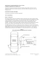
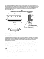
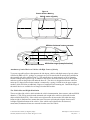
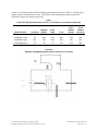
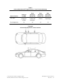
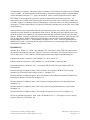
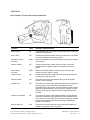
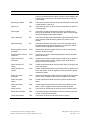
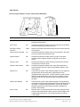
Side Impact Crashworthiness Evaluation Crash Test Protocol (Version VII) May 2014 SIDE IMPACT CRASHWORTHINESS EVALUATION CRASH TEST PROTOCOL (VERSION VI) Supporting documents for the Insurance Institute for Highway Safety (IIHS) side impact crash test program are available from the technical protocols section of the IIHS website (http://www.iihs.org/ ratings/protocols). DOCUMENT REVISION HISTORY A document revision history is provided in Appendix C. TEST CONDITIONS Impact Configuration Side impact crash tests consist of a stationary test vehicle struck on the driver side by a crash cart fitted with an IIHS deformable barrier element. The 1,500 kg moving deformable barrier (MDB) has an impact velocity of 50 km/h (31.1 mi/h) and strikes the vehicle on the driver side at a 90 degree angle. The longitudinal impact point of the barrier on the side of the test vehicle is dependent on the vehicle wheelbase. The impact reference distance (IRD) is defined as the distance rearward from the test vehicle front axle to the centerline of the deformable barrier when it first contacts the vehicle (Figure 1). The MDB alignment calculation was configured to maximize loading to the occupant compartment and allow alignment of the driver dummy head with the flat portion of the barrier face. For most vehicles, the MDB alignment also aligns the rear dummy head with some portion of the barrier. If the alignment calculation allows the flat portion of the MDB face to overlap either the front or rear tires, the impact Figure 1 Moving Deformable Barrier Alignment with Test Vehicle 2014 Insurance Institute for Highway Safety 988 Dairy Rd, Ruckersville, VA 22968. All rights reserved. Side Impact Crash Test Protocol May 2014 — 1 alignment may be modified to prevent direct loading to these structures early in the crash. To date, only one such vehicle has been tested by IIHS, the Smart Fortwo (188 cm wheelbase). Currently, there is no set alignment rule for vehicles that fall into this category, therefore impact alignment will be determined on a case-by-case basis. Manufacturers may contact IIHS for impact point determination and/or confirmation of impact point during the vehicle development process. IRD calculation: If wheelbase 250 cm, then IRD = 144.8 cm If 250 cm wheelbase 290 cm, then IRD = (wheelbase 2) + 19.8 cm If wheelbase 290 cm, then IRD = 164.8 cm The MDB is accelerated by the propulsion system until it reaches the test speed (50 km/h) and then is released from the propulsion system 25 cm before the point of impact with the test vehicle. The impact point tolerance is ± 2.5 cm of the target in the horizontal and vertical axes. The impact speed tolerance is 50 ± 1 km/h. The MDB braking system, which applies the test cart service brakes on all four wheels, is activated 1.0 second after it is released from the propulsion system. The brakes on the test vehicle are not activated during the crash test. IIHS MDB Properties The MDB consists of an IIHS deformable aluminum barrier (version 4) and the cart to which it is attached. The crash cart is similar to the one used in Federal Motor Vehicle Safety Standard (FMVSS) 214 side impact testing but has several modifications (Figure 2). The wheels on the cart are aligned with the longitudinal axis of the cart (0 degrees) to allow for perpendicular impact. The front aluminum mounting plate has been raised 100 mm higher off the ground and has been extended 200 mm taller than a standard FMVSS 214 cart to accommodate the IIHS deformable barrier element (making the mounting plate top surface 300 mm higher from the ground than the FMVSS 214 barrier). Steel plates are added as necessary to increase the mass of the cart. The MDB test weight is 1,500 ± 5 kg with the deformable element, test instrumentation, camera, and camera mount. The MDB center of gravity in the fully equipped test condition is 990 ± 25 mm rearward of the front axle, 0 ± 25 mm from the lateral centerline, and 566 ± 25 mm from the ground. The MDB roll (IX), pitch (IY), and yaw (IZ) moments of inertia are 542 kg-m2, 2,471 kg-m2, and 2,757 kg-m2, respectively. Figure 2 IIHS Test Cart with Deformable Barrier Element Attached 2014 Insurance Institute for Highway Safety 988 Dairy Rd, Ruckersville, VA 22968. All rights reserved. Side Impact Crash Test Protocol May 2014 — 2 The deformable element has a width of 1,676 mm, a height of 759 mm, and a ground clearance of 379 mm when mounted on the test cart (Figure 3). Detailed information on the IIHS barrier development and evaluation testing has been documented previously (Arbelaez et al., 2002). The IIHS deformable barrier design and performance criteria are documented in the Side Impact Moving Deformable Barrier Specification (IIHS, 2007). Figure 3 IIHS Deformable Barrier Element (all measurements in millimeters) Test Vehicle Preparation Test Vehicle Selection and Acquisition Each vehicle is inspected upon arrival at the research center. Vehicles are examined to verify that they are in satisfactory operating condition and to note defects such as prior collision damage, missing parts, maladjustments, or fluid leaks. If directly relevant to testing, such deficiencies are corrected or a replacement vehicle is procured. Some of the vehicles evaluated in the side impact test program have been used in the IIHS bumper test program. Such vehicles have been subjected to an impact on the front and/or rear of the vehicle at either 5 km/h (3.1 mi/h) to the corner or 10 km/h (6.2 mi/h) across the full width (IIHS, 2010). Any structural damage pertinent to side impact protection is repaired or replaced before the side impact crash test. Cosmetic damage is repaired at IIHS discretion. Parts are repaired or replaced as appropriate based on the judgment of professional insurance appraisers. Fluids Gasoline is removed from the fuel tank and fuel lines. The fuel tank then is filled with Stoddard solvent to 90-95 percent of useable capacity. The fuel pump is run for a short period to ensure the Stoddard solvent has filled the fuel lines. Additional fluids may be drained from the vehicle should the vehicle exceed the maximum allowable test weight. 2014 Insurance Institute for Highway Safety 988 Dairy Rd, Ruckersville, VA 22968. All rights reserved. Side Impact Crash Test Protocol May 2014 — 3 High-Voltage Batteries High-voltage batteries in vehicles with hybrid electric and full-electric drivetrains are tested in a charged state as per FMVSS 305, which specifies a maximum state of charge recommended by the manufacturer. If no recommendation is made, the battery is tested at a state of charge of not less than 95 percent of maximum capacity. Maintenance fuses are not removed, but additional precrash and postcrash precautions specified by the vehicle manufacturer are followed. Equipment will be added to the highvoltage system in accordance with manufacturer recommended procedures for monitoring electrical isolation as per FMVSS 305. Thermocouple(s) also will be attached to the high-voltage battery to detect temperature increases that may indicate a thermal runaway condition. Test Vehicle Instrumentation An aluminum instrumentation rack, which supports the test equipment, is installed in the cargo area of the vehicle. The carpeting in this area is removed to allow access to the floor. If necessary, the spare tire, accessory jack, tool compartments, and third row seats may be removed. The following test equipment is installed on the instrumentation rack located in the cargo area: 12-volt battery and monitoring system: This system supplies electrical power for the Diversified Technical Systems (DTS) data acquisition system (DAS), and a wireless bridge for DAS communication. The system weighs 35.2 kg. The wireless device for DAS-to-network communication is mounted to the outside of the vehicle and weighs 1.5 kg. A two-conductor cable connects the 12-volt battery in the instrumentation rack to the vehicle battery terminals. High-speed camera and onboard lighting power supply: This system supplies electrical power to the onboard high-speed video cameras and LED lighting. The weight of the camera/lighting power supply is 26.0 kg. Two camera mount platforms are installed on the nonstruck side of the vehicle at locations adjacent to the front and rear passenger window sills; the front and rear platforms weigh 22 and 12 kg, respectively. Three digital onboard high-speed cameras (500 frames per second), along with a camera router, are mounted on the platforms to observe dummy kinematics throughout the crash. Additionally, three LED lights are mounted inside the vehicle. The total weight of the three digital cameras, mounting hardware, camera router, cables, and lights is 19.6 kg. A plastic block containing an array of high-intensity LEDs is attached to the roof of the vehicle with sheet metal screws. Additional LEDs are placed inside the vehicle in view of the onboard high-speed cameras. A pressure-sensitive tape switch is applied to the driver side of the vehicle such that it makes first contact with the barrier during the crash. Pressure applied to this tape completes an electrical circuit that signals the start of the crash (time-zero) for the data acquisition systems and illuminates all the LEDs. If floormats are standard or offered as an option through the manufacturer or dealership, they are installed in the driver footwell and left rear passenger floorpan. The location of the vehicle precrash longitudinal center of gravity is marked with a photographic target applied to the appropriate top surface of the vehicle (Figure 4). The front passenger head restraint and passenger side windows are removed to prevent possible obstruction of camera views during the test. If the vehicle is equipped with running boards, they are removed unless they are standard equipment across the entire model line for the specific drive configuration being tested (two-wheel or four-wheel drive). 2014 Insurance Institute for Highway Safety 988 Dairy Rd, Ruckersville, VA 22968. All rights reserved. Side Impact Crash Test Protocol May 2014 — 4 Figure 4 Exterior Surface Marking Vehicle center of gravity Vehicle centerline Mid-door horizontal contour measure Impact reference distance MDB sticker target (example location) Attachment of Antiroll Device to Vehicles with High Centers of Gravity To prevent a possible rollover subsequent to the side impact, vehicles with high centers of gravity (those classified by IIHS as SUVs, pickups, or passenger vans) will be tested with an antiroll device attached to the nonstruck side of the vehicle (Figure 5). The antiroll device is made primarily of 4130 Chromoly structural tubing and weighs 42.5 kg. It attaches to the vehicle where the roofrail intersects the B-pillar and at two points on the pinch welds under the door sill. The device is designed to allow the vehicle to rotate up to 5 degrees before further rotation is countered by a spring (14.8 kN/m) in the upper support member, which will allow an additional 5 degrees of rotation before bottoming out. Detailed drawings of the antiroll device are available free of charge from the IIHS website. Test Vehicle Mass and Weight Distribution The test weight of the vehicle, which includes the vehicle instrumentation, three cameras, and two SID-IIs dummies, is 150-225 kg greater than the measured curb weight of the vehicle (as delivered from the dealer with full fluid levels). If the vehicle test weight needs to be increased to fall within the range, ballast weight is distributed in a manner that comes closest to replicating the original front/rear and left/right weight distributions of the vehicle. If the vehicle test weight needs to be decreased, nonessential, nonstructural items are removed from the rear of the vehicle. 2014 Insurance Institute for Highway Safety 988 Dairy Rd, Ruckersville, VA 22968. All rights reserved. Side Impact Crash Test Protocol May 2014 — 5 Figure 5 Antiroll Device for Tests of SUVs, Pickups, and Passenger Vans 2014 Insurance Institute for Highway Safety 988 Dairy Rd, Ruckersville, VA 22968. All rights reserved. Side Impact Crash Test Protocol May 2014 — 6 Driver Seat and Driving Control Placement The driver seat and adjustable steering controls are adjusted according to the Guidelines for Using the UMTRI ATD Positioning Procedure for ATD and Seat Positioning (Version V) (IIHS, 2004). The outboard upper seat belt anchorage point (if adjustable) is set in the full-down position, unless otherwise specified by the test vehicle manufacturer. After the driver seat has been adjusted, the latching mechanism is examined to note whether all of its components are interlocked. If partial interlocking is observed and normal readjustment of the seat does not correct the problematic misalignment, the condition is noted and the test is conducted without repairing the mechanism. The right front passenger seat is set to match the position of the driver seat. The driver head restraint (if manually adjustable) is set in the full-down position, unless otherwise specified by the test vehicle manufacturer. The head restraint height adjustment locking mechanism (if equipped) is examined to ensure the mechanism has engaged. All manually adjustable head restraint tilting mechanisms are adjusted to their full-rearward position. The driver seat manually adjustable inboard armrest (if equipped) is moved to its lowered position. For vehicles equipped with multiple locking armrest positions, the position that results in the top surface of the armrest being closest to parallel with the ground is chosen. When seats have inboard and outboard armrests, both are placed in the lowered position. Rear Passenger Seat Placement If applicable, the rear passenger seat is positioned according to the Dummy Seating Procedure for Rear Outboard Positions (IIHS, 2005). If manually adjustable, the rear passenger head restraint is set in the full-down position, unless otherwise specified by the test vehicle manufacturer. In cases where the head restraint can be lowered for stowage or positioned for non-use, it shall be set to the first usable locking position. All manually adjustable head restraint tilting mechanisms are adjusted to their full-rearward position. The rear seat manually adjustable inboard armrest (if equipped) is moved to its lowered position. For vehicles equipped with multiple locking armrest positions, the position that results in the top surface of the armrest being closest to parallel with the ground is chosen. When seats have inboard and outboard armrests, both are placed in the lowered position. Side Windows and Door Locks The nonstruck side doors are fully latched and locked, whereas the struck side doors are fully latched but not locked. However, if the vehicle is equipped with automatic locking doors that cannot be set to remain unlocked when the vehicle is in forward motion, the struck side door locks are kept in their automatic state. The front and rear driver side windows are fully raised. Transmission and Ignition The ignition is turned to its on position, and the transmission is shifted into its neutral position prior to the test. The front left tire is chocked to prevent the vehicle from moving prior to the test. 2014 Insurance Institute for Highway Safety 988 Dairy Rd, Ruckersville, VA 22968. All rights reserved. Side Impact Crash Test Protocol May 2014 — 7 Crash Dummy Preparation and Setup A 5th percentile female SID-IIs dummy is positioned in the driver seat according to the Guidelines for Using the UMTRI ATD Positioning Procedure for ATD and Seat Positioning (Version V) (IIHS, 2004). A second SID-IIs dummy is positioned in the left rear seat according to the Dummy Seating Procedure for Rear Outboard Positions (IIHS, 2005). Standard Build Level D SID-IIs (Humanetics Innovative Solutions, 2011) dummies are used for the IIHS side impact program. The dummy has been modified by removing the upper and lower shoulder rib stops on the spine box (Humanetics Innovative Solutions, Inc., part numbers 180-3369 and 180-3370). Removal of the shoulder rib stops restores the shoulder deflection to the range that was allowable in the Standard Build Level C SID-IIs. The Build Level D shoulder potentiometer (Humanetics Innovative Solutions, Inc., part number 180-3381) has been replaced with a potentiometer (Humanetics Innovative Solutions, Inc., part number 180-3382) that has a longer travel range. Photographic targets are placed on both sides of the head to mark the location of its center of gravity. The dummies used in these tests are calibrated according to 49 CFR 572 (V) after being subjected to no more than five crash tests. Additionally, the shoulder, thorax, and abdomen regions are individually recalibrated if deflections recorded during a test exceed 50 mm or if postcrash inspection reveals damage. All visible damage is repaired before the dummy is used again. The dummies and vehicle are kept in a climate-controlled area in the crash hall where the temperature is maintained at 20.0-22.2 degrees Celsius and the relative humidity at 10-70 percent for at least 16 hours prior to the test. The driver and rear passenger seat belts are fastened around the dummies. For vehicles with continuous-loop lap/shoulder seat belts, the slack from the lap portion of the driver seat belt is removed, and the webbing is pulled fully out of the retractor and allowed to retract under tension a total of four times. The lap belt slack then is removed again with a small pulling force. For vehicles with separate lap and shoulder seat belt retractors, the webbing from each is pulled fully out of the retractor and allowed to retract under tension a total of four times. Prior to the crash, the heads of both dummies are colored with grease paint to facilitate postcrash identification of impacts with the vehicle interior and/or the striking barrier face. Photography Still Photography The precrash and postcrash conditions of each test vehicle are photographed. Two precrash and two postcrash views show the side and left front quarter of the test vehicle. Additional photographs document the precrash position of the driver and rear passenger dummies. Three standard views each of the vehicle and MDB together in their postcrash positions, of the struck side of the vehicle, and of the MDB face are recorded. Additional photographs document the postcrash positions of the driver and rear passenger dummies, as well as any paint transfer areas due to dummy contact with the vehicle or MDB. Once the dummies are removed from the vehicle, both seating compartment areas are photographed as a means of illustrating vehicle intrusion. Additional photographs are taken with the struck side doors removed. High-Speed Motion Picture Photography Motion picture photography is made of the test with nine high-speed digital imagers along with real-time cameras. The coordinates and lens focal length of each offboard camera are listed in Table 1. The 2014 Insurance Institute for Highway Safety 988 Dairy Rd, Ruckersville, VA 22968. All rights reserved. Side Impact Crash Test Protocol May 2014 — 8 camera view and focal length of the onboard high-speed cameras are listed in Table 2. All high-speed imagers record at 500 frames per second. The positions of the offboard and onboard cameras are illustrated in Figures 6A and 6B, respectively. Table 1 Crash Hall High-Speed Phantom Cameras – Coordinates, Focal Points, and Settings A B Camera Position Overhead Left Side Oblique Coordinate X (cm) -16 Coordinate Y (cm) C D E F Front High Front Front Oblique (driver) Front Oblique (drv-pass) -536 -33 -18 415* 415* -33 1350 768 668 740* 740* Coordinate Z (cm) 910 149 194 250 146 146 Focal length (mm) 35 50 95 100 135 200 *Varies by vehicle size and type Figure 6A Offboard and MDB High-Speed Camera Positions in Crash Hall 2014 Insurance Institute for Highway Safety 988 Dairy Rd, Ruckersville, VA 22968. All rights reserved. Side Impact Crash Test Protocol May 2014 — 9 Table 2 Onboard High-Speed IDT Digital Cameras – Focal Points and Settings Camera Position Focal point Focal length (mm) G H I J Centered On MDB Impact from perspective of MDB Front Passenger Window Sill Oblique view of driver and passenger Front Passenger Window Sill Lateral view of driver Rear Passenger Window Sill Lateral view of passenger 10 10 16 10 Figure 6B Onboard High-Speed IDT Camera Positions 2014 Insurance Institute for Highway Safety 988 Dairy Rd, Ruckersville, VA 22968. All rights reserved. Side Impact Crash Test Protocol May 2014 — 10 MEASUREMENTS AND OBSERVATIONS Test Weight The test weight of the vehicle is measured at each of the four wheels. The vehicle is weighed with all test equipment installed (ballast weight is added to account for the driver and passenger dummies). In tests of SUVs, pickups, and passenger vans, the test weight is measured without the antiroll device attached. The front and rear axle weights are used to determine the longitudinal position of the center of gravity for the test vehicle. Impact Speed The barrier impact speed is determined by averaging two speed trap measurements. Both speed traps measure the average velocity of the barrier between 1.0-1.5 m before impact with the vehicle. The propulsion system also has an optical speed measuring device that serves as a backup to the two speed traps. This device measures the speed of the hardware attaching the barrier to the propulsion system immediately prior to barrier’s release from the propulsion system before impact. The speed is clocked over a 1 m length of vehicle travel ending 0.5 m before the barriers’s release from the propulsion system. Impact Point A threaded 0.125 inch (3 mm) rod with a sharpened tip is attached to a tapped hole in the leading edge of the MDB bumper aluminum cladding. The horizontal location of this impact striker is selected such that it contacts the vehicle structure rearward of the driver door at the point of impact. The impact striker extends 20-30 mm from the front edge of the barrier face, thus it makes first contact between the barrier and the vehicle. A 3 inch (76 mm) diameter photo target is placed on the vehicle (Figure 4) so that the tip of the impact striker is located in the center of the target during precrash vehicle positioning. At the point of impact, the striker punctures the target, thus providing an indication of the initial MDB alignment with respect to the vehicle. Vehicle Accelerations The lateral acceleration of the vehicle occupant compartment is measured (Endevco 7264B-2000 or 7264A-2000 accelerometers) at two locations on the floor, just rearward of the A- and B-pillars (nonstruck side), and recorded by the data acquisition system. Positive vehicle accelerations are to the right along the lateral axis. The data are presented filtered according to the channel frequency class (CFC) 60 as defined in SAE J211 – Instrumentation for Impact Tests (Society of Automotive Engineers (SAE), 2000). Fuel System Integrity Observations about fuel system integrity are recorded for each test. Any Stoddard fluid leaked from the fuel system within 1 minute after the impact is collected as the first sample. This typically is done by soaking up the fluid with an absorbent pad of known mass. The second sample of leaked Stoddard fluid is collected during the 5 minutes immediately following the collection of the first sample. This sample typically is collected in pans placed under the sources of identified leaks. The third sample is collected during the 25 minutes immediately following the collection of the second. The pans used to collect the second sample are replaced with clean empty pans. The volume of each sample is determined by dividing the weight of the sample by the density of Stoddard fluid (790 g/l). The elapsed time is determined using a stopwatch. The entire process is recorded with a video camera equipped with an internal timer, which displays the time in each frame. 2014 Insurance Institute for Highway Safety 988 Dairy Rd, Ruckersville, VA 22968. All rights reserved. Side Impact Crash Test Protocol May 2014 — 11 High-Voltage System Integrity Vehicles with a hybrid or full-electric drivetrain are monitored to ensure the high-voltage electrical system has not been compromised. Postcrash observations include a measure of electrolyte spillage (if any), battery retention, and electrical isolation of the high-voltage system as per FMVSS 305. Additionally, the battery temperature will be monitored to detect a rapid increase in temperature that may indicate a thermal runaway condition. Following the crash, power will be drained from high-voltage systems in a manner specified by the manufacturer. Vehicle Crush Profile and Compartment Intrusion The spatial coordinates of the test vehicle B-pillars and profile of the driver side structure are measured before and after the crash. A horizontal contour line is marked on the driver side of the vehicle at the level of the mid-door (Figure 4) and then recorded using a coordinate measuring machine (Romer CimCore Inc.). This contour line is measured after the crash using the same reference coordinate system. Precrash measures are recorded on the struck side B-pillar exterior and the nonstruck side B-pillar exterior and interior (with interior trim removed); postcrash measures are recorded on the struck side B-pillar exterior and interior (with interior trim removed). Precrash measures on the struck side B-pillar interior are not recorded due to the possibility that removal and reattachment of the interior trim could affect the deployment of roofrail-mounted head curtain airbags. A mirror image of the nonstruck side B-pillar interior vertical profile will be used to determine the relative movement of the B-pillar interior. Figure 7 shows an example of precrash and postcrash B-pillar vertical profile measures. Coordinate System Definition A right-handed, three-axis orthogonal coordinate system is used for these measures: longitudinal (front to rear is positive), lateral (left to right is positive), and vertical (bottom to top is positive). The precrash coordinate system is defined with the vehicle unloaded (no occupants) on a level floor. The plane of the ground is used to define the X-Y plane, and the two end points on the centerline of the roof are used to define the X-axis (Figure 4). Coordinates of three marked reference points on the nonstruck side vehicle structure are recorded before the crash to establish the postcrash coordinate system. 160 Figure 7 Example B-Pillar Vertical Profiles Height f rom ground (cm) 140 120 100 Mirror image of nonstruck side B-pillar interior 80 60 Mid-door height 40 Precrash 20 Postcrash 0 -100 -80 -60 -40 -20 0 20 40 60 80 Lateral distance f rom vehicle centerline (cm) 2014 Insurance Institute for Highway Safety 988 Dairy Rd, Ruckersville, VA 22968. All rights reserved. 100 Side Impact Crash Test Protocol May 2014 — 12 Dummy Kinematics and Contact Locations Both dummies are inspected in their undisturbed postcrash positions. Any damage to or unusual final resting position observed for either dummy is documented. The locations of grease paint transferred from the heads of the dummies to the vehicle interior and/or barrier face are noted and photographed. Any entrapment of the lower extremities also is documented when the dummies are extricated from the vehicle. Review of the high-speed video helps determine dummy kinematics and estimate the time after the start of the crash that various events occur. For each event, the camera that provides the clearest view of the event is used. The start of the crash is considered to be the first frame in the video from each camera in which the LEDs mounted on the roof and inside the vehicle are illuminated. The time recorded for each event is based on the number of frames elapsed from the start of the crash and the nominal operating speed of the camera. For the cameras operating at 500 frames per second, the estimate of the crash start time can be up to 2 ms late, and the event time, as determined from the film, can be early or late by 2 ms. The times of the driver and passenger side airbag deployments, full inflation, and first dummy contacts are recorded as well as any other notable events. Dummy Responses Each SID-IIs dummy is equipped with instrumentation for measuring the following: Head Tri-axial accelerations (three Endevco 7264B-2000 or 7264A-2000 accelerometers) Triaxial angular rate sensors (three DTS ARS Pro – 18k) Neck A-P shear force L-M shear force Axial force L-M moments Twist moments (Humanetics IF-205 or Humanetics 1716A load cell) Shoulder Triaxial forces (Humanetics IF-344 or Humanetics 3167 load cell) Lateral shoulder compression (Humanetics 180-3882 0.5 inch linear potentiometer) Spine T1, base of the neck, lateral acceleration (Endevco 7264B-2000* accelerometer) T4, first thoracic rib level, lateral acceleration (Endevco 7264B-2000* accelerometer) T12, first abdominal rib level, lateral acceleration (Endevco 7264B-2000* accelerometer) Chest and Abdominal Ribs (three thorax and two abdominal ribs) Struck side lateral rib accelerations (Endevco 7264B-2000 or 7264A-2000 accelerometers) Lateral rib compressions (Humanetics 180-3881 0.5 inch linear potentiometers) Pelvis Lateral acceleration (Endevco 7264B-2000 or 7264A-2000 accelerometers) Lateral acetabulum force (Humanetics IF-520 or Humanetics 3249 load cell) Lateral ilium crest force (Humanetics IF-507 or Humanetics 3228 load cell) Lower Extremities Left lower femur L-M force and L-M and A-P moments (Humanetics IF-625 or Humanetics 1914A load cell) 2014 Insurance Institute for Highway Safety 988 Dairy Rd, Ruckersville, VA 22968. All rights reserved. Side Impact Crash Test Protocol May 2014 — 13 All instruments are regularly calibrated to a known standard. Accelerometers and load cells are calibrated every 12 months. All measurements recorded from these instruments comply with the recommendations of SAE Information Report J1733 – Sign Convention for Vehicle Crash Testing DEC94 (SAE, 2000). DTS TDAS G5 data acquisition systems are used for all dummy and vehicle data acquisition. All measurements are recorded in the system random access memory with 16-bit resolution at a sample rate of 10 kHz. Signals in all channels convert simultaneously, so the time reference for different channels is not skewed. To ensure digital fidelity, all signals are filtered by an analog low-pass prefilter with a 3 kHz cutoff frequency. After the data have been downloaded from the data acquisition systems, any initial offset from zero is removed from each channel by computing the mean value for 100 data points preceding the crash event (from 50 to 40 ms before impact) for each channel and subtracting each mean from the respective data channel. With the exception of rib deflection and pelvis acceleration data, which are filtered to SAE CFC 180, all other data are digitally filtered using the frequency response classes recommended in SAE Recommended Practice J211/1 – Instrumentation for Impact Test – Part 1, Electronic Instrumentation MAR95 (SAE, 2000). All filtering and subsequent calculations are executed using DIAdem (National Instruments Corporation, 2010). REFERENCES Arbelaez, R.A.; Dakin, G.J.; Nolan, J.M.; Dalmotas, D.J.; and Tylko, S. 2002. IIHS side impact barrier: development and crash test experience. IMechE Conference Transactions: International Conference on Vehicle Safety 2002, 73-88. London, United Kingdom: Professional Engineering Publishing Ltd. National Instruments Corporation. 2010. DIAdem Ver. 2010. Austin, TX. DSP Development Corporation. 2002. DADiSP Ver. 6.0 NI NK B03. Cambridge, MA. Humanetics Innovative Solutions. 2011. User manual SID-IIs small side impact dummy (SBL D). Plymouth, MI. Insurance Institute for Highway Safety. 2004. Guidelines for using the UMTRI ATD positioning procedure for ATD and seat positioning (version V). Arlington, VA. Insurance Institute for Highway Safety. 2014. Side Impact Crashworthiness Evaluation, Guidelines for Rating Injury Measures (version III) Arlington, VA. Insurance Institute for Highway Safety. 2005. Dummy seating procedure for rear outboard positions. Arlington, VA. Insurance Institute for Highway Safety. 2007. Side impact moving deformable barrier specification. Arlington, VA. Insurance Institute for Highway Safety. 2010. Bumper test protocol (version VI). Arlington, VA. Society of Automotive Engineers. 2000. 2000 SAE Handbook, Vol. 3 – On-Highway Vehicles and OffHighway Machinery. Warrendale, PA. 2014 Insurance Institute for Highway Safety 988 Dairy Rd, Ruckersville, VA 22968. All rights reserved. Side Impact Crash Test Protocol May 2014 — 14 APPENDIX A Driver Dummy Clearance Measurement Definitions Location Code Definition of Measurement Ankle to ankle AA Taken between the center points of both ankles, after the feet are placed per IIHS protocol. Arm to door AD Horizontal measurement taken from the center point of the elbow to the first contact point of the door panel. Armrest to dummy, minimum ADM Minimum horizontal measurement taken from the vehicle armrest to the dummy. Head to A-pillar HA Horizontal measurement taken from the center of the head outboard center of gravity target to the A-pillar (not shown in figure). Hub to chest, minimum HCM Minimum horizontal distance measured from the hub to the dummy chest (not shown in figure). H-point to door HD Horizontal measurement taken from the H-point hole to the first contact point of the door panel. Head to header HH Taken from the center point between the eyes to the header directly in front of dummy. Head to roof HR Taken from the center of the outboard target to the roof edge (not the upper edge of the vehicle door), perpendicular to the longitudinal axis of the vehicle. If a tape measure is held from the target and extends below the roof, the point to measure is at the low edge of the roof line, which will make contact with the tape measure. Head to side window HS Taken from the center of the outboard target to the side window, measured horizontally and perpendicular to the longitudinal axis of the vehicle. In cases where the window is not fully up, a flat bar should be placed across the window opening to simulate the position of the window. Knee to dash, left KDL Taken from the knee pivot point to the point on the dash that is directly level with the center of the knee. continued 2014 Insurance Institute for Highway Safety 988 Dairy Rd, Ruckersville, VA 22968. All rights reserved. Side Impact Crash Test Protocol May 2014 — A-1 Location Code Definition of Measurement Knee to knee KK With the legs in a vertical plane after the feet are placed per IIHS protocol, the measurement is taken from the outside flange to the outside flange of the knees. The minimum distance is 270 mm (10.6 inches). Neck angle, seated NAS Taken from the neck when the dummy is seated across two of the “vertebral disks” of the neck. Nose to rim NR Taken from the tip of the nose to the steering wheel rim at the 12 o’clock position. Pelvis angle PA Taken from the instrumented pelvis sensor (if available) or by placing an inclinometer on the H-point bar, which is used to align the H-point with previous measurements. Rim to abdomen RA Taken from the point where the bottom of the chest jacket and the pelvis structure meet the steering wheel rim at the 6 o’clock position. Seat back angle SA Taken from the lower left corner of the driver seat back unless otherwise directed by the manufacturer, at which time it will be properly noted along with the measurement. Steering wheel to chest, horizontal SCH Horizontal measurement taken from the center of the steering wheel to the dummy chest. Steering wheel to chest, reference SCR Taken from the center of the steering wheel to the top rib guide (SID-IIs dummies). Striker to head CG, horizontal CGH Horizontal measurement taken from the head center of gravity to the driver door striker. Value is negative if the head center of gravity is forward of the striker. Striker to head CG, lateral CGL Lateral measurement taken from the head center of gravity to the driver door striker. Striker to head CG, vertical CGV Vertical measurement taken from the head center of gravity to the driver door striker. Value is negative if the head center of gravity is below the striker. Striker to H-point, horizontal SHH Horizontal measurement taken from the H-point to the driver door striker. Value is negative if the H-point is forward of the striker. Striker to H-point, lateral SHL Lateral measurement taken from the H-point to the driver door striker. Striker to H-point, vertical SHV Vertical measurement taken from the H-point to the driver door striker. Value is negative if the H-point is below the striker. Striker to knee SK Taken from the center point of the knee to the front door striker. Striker to knee angle SKA Calculated using the coordinates of the knee pivot point and the location of the driver door striker. Torso recline angle TRA Taken from the H-point to the head center of gravity. 2014 Insurance Institute for Highway Safety 988 Dairy Rd, Ruckersville, VA 22968. All rights reserved. Side Impact Crash Test Protocol May 2014 — A-2 APPENDIX B Rear Passenger Dummy Clearance Measurement Definitions Location Code Definition of Measurement Ankle to ankle AA Taken between the center points of both ankles, after the feet are placed per IIHS protocol. Arm to door AD Horizontal measurement taken from the center point of the elbow to the first contact point of the door panel. Armrest to dummy, minimum ADM Minimum horizontal measurement taken from the vehicle armrest to the dummy. Chest to seat, horizontal CS Horizontal measurement taken from the top rib guide in the chest to a point on the back of the driver seat. Head to B-pillar HB Horizontal measurement taken from the center of the head outboard center of gravity target to the B-pillar (not shown in figure). H-point to door HD Horizontal measurement taken from the H-point hole to the first contact point of the door panel. Head to head restraint HHR Horizontal measurement taken from center point between the eyes to the back side of the driver head restraint directly in front of the dummy. Head to roof HR Taken from the center of the outboard target to the roof edge (not the upper edge of the vehicle door), perpendicular to the longitudinal axis of the vehicle. If a tape measure is held from the target and extends below the roof, the point to measure is at the low edge of the roof line, which will make contact with the tape measure. Head to side window HS Taken from the center of the outboard target to the side window, measured horizontally and perpendicular to the longitudinal axis of the vehicle. In cases where the window is not fully up, a flat bar should be placed across the window opening to simulate the position of the window. Knee to knee KK With the legs in a vertical plane after the feet are placed per IIHS protocol, the measurement is taken from the outside flange to the outside flange of the knees. The minimum distance is 270 mm (10.6 inches). continued 2014 Insurance Institute for Highway Safety 988 Dairy Rd, Ruckersville, VA 22968. All rights reserved. Side Impact Crash Test Protocol May 2014 — B-1 Location Code Definition of Measurement Neck angle, seated NAS Taken from the neck when the dummy is seated across two of the “vertebral disks” of the neck. Pelvis angle PA Taken from the instrumented pelvis sensor (if available) or by placing an inclinometer on the H-point bar, which is used to align the H-point with previous measurements. Seat back angle SA Taken from the lower left corner of the rear passenger seat back unless otherwise directed by the manufacturer, at which time it will be properly noted along with the measurement. Striker to head CG, horizontal CGH Horizontal measurement taken from the head center of gravity to the rear door striker. Value is negative if the head center of gravity is forward of the striker. Striker to head CG, lateral CGL Lateral measurement taken from the head center of gravity to the rear door striker. Striker to head CG, vertical CGV Vertical measurement taken from the head center of gravity to the rear door striker. Value is negative if the head center of gravity is below the striker. Striker to H-point, horizontal SHH Horizontal measurement taken from the H-point to the rear door striker. Value is negative if the H-point is forward of the striker. Striker to H-point, lateral SHL Lateral measurement taken from the H-point to the rear door striker. Striker to H-point, vertical SHV Vertical measurement taken from the H-point to the rear door striker. Value is negative if the H-point is below the striker. Striker to knee SK Taken from the center point of the knee to the rear door striker. Striker to knee angle SKA Calculated using the coordinates of the knee pivot point and the location of the rear door striker. Torso recline angle TRA Taken from the H-point to the head center of gravity. 2014 Insurance Institute for Highway Safety 988 Dairy Rd, Ruckersville, VA 22968. All rights reserved. Side Impact Crash Test Protocol May 2014 — B-2 APPENDIX C Document Revision History Revisions to Version VII of the protocol comparted to Version VI: Explanation of dummy injury measure calculations was moved to the Side Impact Guidelines for Rating Injury Measures. The removal of the shoulder rib stops from the SID-II’s outlined. The weight of the onboard test equipment was updated. The maximum allowable test weight above measured curb weight was increased from 200 kg to 225 kg. The photography section now indicates high-speed digital imagers are now used instead of high-speed film cameras. Crash hall positions of the cameras have also been updated. Additional instruction of where to place the rear passenger head restraint in cases where it can be stowed for non-use. Revisions to Version VI of the protocol compared with Version V: IRD is now measured from front axle to barrier centerline. High-voltage systems found in vehicles with electric drivetrains are discussed in the Test Conditions and Measurements/Observations sections. Denton IDDAS DAS no longer used. SID-IIsD dummy is now being used to match the regulated version of the dummy being used by the National Highway Traffic Safety Administration. Data processing is now conducted with the DIAdem software program. Revisions to Version V of the protocol compared with Version IV: The method of determining the impact point for vehicles with very short wheelbases may deviate from the impact point defined by the impact reference distance calculation. Impact point and impact speed tolerances of ± 2.5 cm and ± 1 km/h have been added. The reference to and specifications for the IIHS low-speed bumper test program have been replaced with the IIHS bumper test program. Additional detail has been provided for the weight of the on-board cameras, data acquisition units, and the platforms used to support them. Clarification has been provided for the treatment of vehicles equipped with running boards. If a vehicle is equipped with automatic locking doors that cannot be set to remain unlocked when the vehicle is in motion, the struck side door locks are kept in their automatic state. Either Humanetics IDDAS or DTS TDAS G5 data acquisition systems may be used to record all dummy and vehicle data. Both units are being used during an interim period, after which only the TDAS G5 units will be used as part of an in-dummy data acquisition system. Revisions to Version IV of the protocol compared with Version III: The reference list reflects recent updates to the Guidelines for Using the UMTRI ATD Positioning Procedure for ATD and Seat Positioning (Version V). Precrash and postcrash vehicle crush profiles measured at the window sill and rocker panel and the door vertical profiles measured at the driver and rear passenger H-point locations have been eliminated. Precrash and postcrash crush profile measures of the moving deformable barrier (MDB) deformable element have been eliminated. 2014 Insurance Institute for Highway Safety 988 Dairy Rd, Ruckersville, VA 22968. All rights reserved. Side Impact Crash Test Protocol May 2014 — C-1 Revisions to Version III of the protocol comapred with Version II: The MDB vertical center of gravity was updated to reflect official measurements taken at an inertial measurement facility. Roll, pitch, and yaw moments of inertia also were added to the MDB specifications. Revisions to Version II of the protocol compared with Version I: In addition to postcrash photographs of the vehicle taken with the struck side doors on, photos are taken with the door skins removed, then again with the doors removed. Additional structural measures are recorded on the struck and nonstruck side B-pillar interior. In addition, the postcrash coordinate system is now reestablished using reference points that are recorded precrash. The pubic force load measurement was eliminated. 2014 Insurance Institute for Highway Safety 988 Dairy Rd, Ruckersville, VA 22968. All rights reserved. Side Impact Crash Test Protocol May 2014 — C-2