1
;
I}
•
,-J
' /
'
/
�- .:.--
-
_, ...
't-
-
0
/1,,-J
· ,
+.-
(
f' ·' j'�l.:\\y
·
� Jt;
'
;1 ; 7(-'
·
kf
''\'\
'
1,-·;n,t1r'l'lt:q
1
I
--
J.
t.--t n , ;-J
�'77G. <:_;\
de
�c;,·l
C,')
i'\c,
.
�c,
l)/
•�<12tj/(�
I.._'P�(� ,
Fcr th.:;.+' r·�l ('It e d q ciHb It i'fa·t-5"1/· d.; >�do i'
•1-t. ""Ide YVl.
Tf,c::.c: 1:)
AvLdTft,CI·t t-l1e CC:8'(i(1).1 ')''-t.) rr;<t::: r�+, c.. �if:\ - q
pc�,;,;,-T t{ I
j'' ·t Yl .v.; +h ·ry,-c,�c,... I\ \It:· !o rr·'rl t
,...,
e
t)C
c
".>
�
t'
Dcsu�AI:-:tLE AJ)J)i f/CrVS:
,
.
¢
b, 0. S.
ExT E r ) E ·D
'
TE.)<'I
5".
til):) i c
7,
Mt:·F.E
(,
PRE..C 1,:
•
"
1-1 F 1 L- E 5.
)Sti'-'\BL-.Lr.¢.
J);_r;;,/-)
tr'1J
I-:. \�,
.
(
• •
,
i I-_
_.
- ,
.I
�)t
•
I
vc �
'E
- I�
L,
'.
-·
� t·
�
;:;.. u ·' ,/17 • L
.
;,\-
>S£l'-1BLE)
t<../:
fLGI
;J �=t..� L
-
.:>
1 -
'.,.• L .,.,_� c.
l
I; I · '
I L,� I l
!)
71 �:. Pt'0C- ({1)!'11'-1 EK..
S':')
.< ,.
)TE.M
''
I
.
I
,
-
_.
l
.... ,
\rtt_..'- \
u·· .
.
c
3-.D
DI:"EN- L. 'r\i E:/Pi_A,\tES�
. '
I' 'l
' '
;-
t
I
'
... ,, t:
.... ,
;f\.\G
1�CL�
DiAGf2.AM cA f'A B; ,__, Tt L-S 7 tV�--�� r:. d 1
At� !'> '" '\B .J!Ti"t.-f f I :; j\l -- p. j- E t..t: iVl t NT Ft<Oi 1
i
o(\U�·)
E
,_,
7ti>'C f RuG k./W)M E
�
,
•.v t 1
1 y .;,\ \ ""
!C:j\1./" ;� lt�RL �A f) E t:.'lt-TRA -(/) LCt.-1 Lf) FC
� D i TCI' /sELECT: I c :r.�· {It: eFT JJ\) s S .
c·r� FuK 1 /<..A tv' C r.l\ i' i L- r f' . ( ·lc E. .L --c. K -,.-.ET E {:.)
3. VI1RI/7 Ki...E..
Y.
,
· '
·.,·j '.)G.i' 1
�'�
·�As i c
f\-1ACRC -p
P.tLCJ ATP·b�.-E
2..
(n�Y
,
!
T"/� 13 L E <) '
)
�
1
- , t. l• r L
•
.
I '
I t:::.:.
- I 1 I ':'I ',
1
:
I..
•·
•
'
,"i ...
I .
..... .
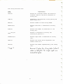
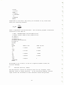
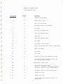
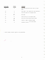
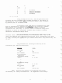
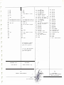
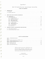
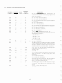
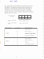
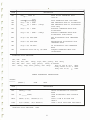
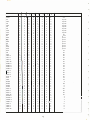
BASIC8001
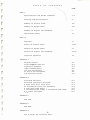
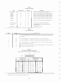
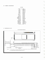
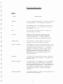
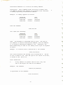
T A B L E
0 F
C 0 N T E N T S
PAGE
Introduct ion
l-2
Summary o f Commands
3- 8
E rror Me s s ages
9- l l
BASIC 8 0 0 1 Ari thme tic
12-17
BASIC 8 0 01 S trings
18- 2 0
BAS IC 8 0 0 1 Immediate Mode
21-23
BASIC 8 0 0 1 S ta tements
2 4- 4 1
BASIC 8 0 0 1 Ari thme tic Func tions
42-50
BAS IC 8 0 0 1 User Define Functions
51-53
BASI C 8 0 0 1 S tring Functions
54-55
BAS I C 8 0 0 1 Edi ting Commands
56-60
Us ing As s embly Language Routines
with BAS IC
61
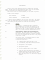
BAS IC 8 0 0 1
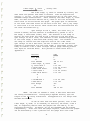
INTRODUCTION
BAS IC 8 0 0 1 is a s ingl e-user, conversational programming l anguage which
uses simple Engl i sh - type statements and fami l iar mathemat i c a l notations
BAS IC 8 0 0 1 is one of the s impl e st computer
to perform an operation.
language s to le arn and once le arned has the fac i l ity of advanced tech
niques to perform more intri cate manipulations or expre s s a problem
more e f fic iently.
BAS IC 8 0 0 1 is in inc remental compiler which provide s immediate translation
and storage of user programs be ing input.
Th is method decre a s e s the
respon se time of a RUN command and increa s e s exe cution speed.
BAS IC 8 0 0 1
h a s provi sion for a lphanumeric character string., I / 0 and string variables,
and a l lows user de fined functions and as sembl y language subroutine cal l s
from user BAS IC 8 0 0 1 programs .
BAS IC 8 0 0 1 can be run on any Intecolor 8 0 0 1, Inte color 8 0 5 1 or Compuco lor
8001 with a min imum of 8K o f user workspace.
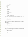
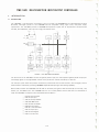
LOAD ING AND RUNNING BAS IC 8 0 0 1
BAS IC 8 0 0 1 is provided in ROM and runs l n ROM .
BAS IC 8 0 0 1 i s initi ated b y
The dialogue des cribed be low
typing the E S C key, then the W ( BAS IC ) key.
is printed .
Thi s is a once-only dialogue and do e s not o c c ur a fter an ESC
key, and E key sequenc e .
The READY me s s age is printed a fter the ESC, E key
sequence .
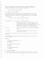
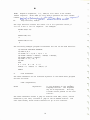
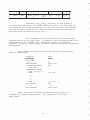
BAS IC 8 0 0 1 prints :
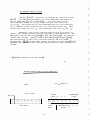
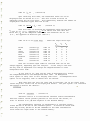
BAS IC 8 0 0 1 Vl2 /8/76 COPYRIGHT ( C )
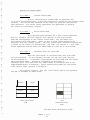
MAXIMUM
RAM
1 976 BY CHARLES MUENCH
ADDRESS ?
The user then type s the highest RAM address that he has avai lable or wants
to use and then keys a c arriage return.
2 '3 \ S�T e:.s use.o
� ce.s-535 -2@1/fSrD :=. 11 F FF HE.i<
1"\IDDLE:.. o;: (I�ST W1fVI C:Af::p: Lj5CP)�
FoR
INI\IAC..!Z:�ralN
=�'553S-If>38"/ = BFFF"'u.
One extra RAM c ard i s 4 9 1 5 1
OF �AS(C �<PcDI STIJ'TliS.
Two extra RAM c ards i s 57 3 4 3 :.(055.35- 81'JZ. = 'Df'FFhc,..,
Three extra RAM c ards i s 6 5 5 2 9 = "SS3i-b
: FFF9. \-.e.)C.
2'i7 6':\T£-S tA�El>
I
BAS IC 8 0 0 1 then prints the mes sage,
AA"t.R. �0 ( N& .AN!1�1 M$-.
READY
and waits for a command or program l ine to be typed .
I f BAS IC 8 0 0 1 has been initial ized as above but has returned to the CRT
O . S . ( by CPU Re set Key ) , then BAS IC 8 0 0 1 can be recal l ed without di sturbing
exi sting programs by typing the ESC key, then the E key .
BAS IC 8 0 0 1 w i ll
then print the me s sage READY.
..
1
If power fails , the CPU Re set key is hit or the unit i s turned o f f ,
the un it re turn s to the CRT operating mode .
If the CPU Re set key or ESC delete keys are hit , the unit leaves
BASIC 8 0 0 1 and re turns to the CRT operating mode . Any BASIC 8 0 0 1
statement program i s s aved and can later b e recalled i f BAS IC 8 0 0 1
i s re -entered b y typing ESC , E .
BAS IC 8 0 0 1 has twenty- four ( 2 4 ) key word program s ta tement s , thirteen
( 1 3) editing and command statements , eighteen ( 18 ) mathematical func tion s ,
nine ( 9 ) string func tion s and eighteen ( 18 ) two-letter error me s s age s .
With the s e command and statement capabilities , BASIC 8 0 0 1 i s extremely
simple to use and yet very vers atile and powe rful .
The next section provides an easy re ference to BASIC 8 0 0 1 c apab i litie s .
If the user i s unfamiliar with BASIC 8 0 0 1 language, then the remaining
portion of thi s manual should be studied in sequence while having a
terminal at your fingertips to run the example given .
Thi s manual
should enable the user to become very pro fi c ient in BASIC 8 0 0 1 when
fini shed .
Intelligent Sys tems Corporation and Compucolor Corporation
have a number of BASIC 8 0 0 1 programs on Floppy Tape s and are avai lable
In addition , both companies will pay for BASIC 8 0 0 1
at nominal price s .
programs that are provided o n floppy tape when properly documented and
accepted .
En j oy your self programming in BAS IC 8 0 0 1!
2
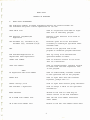
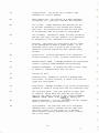
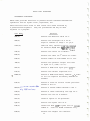
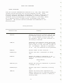
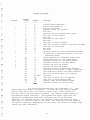
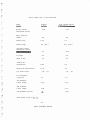
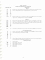
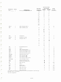
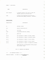
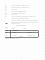
BAS IC 8 0 0 1
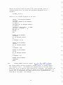
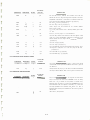
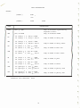
SUMMARY OF COMMANDS
1.
BAS IC 8 0 0 1 STATEMENTS
The following summary of BAS I C s tatements defines the general format for
the s tatement and give s a bri e f explanation o f its use.
DATA value list
Used in con j un ction with READ to input
data into an e xecuting program.
DEF function ( argument )
expre s s ion
Defines a user func tion to be used i n
the program.
DIM variable ( n ) , variable ( n , m ) ,
variable $ ( n ) , var iable $ ( n , m)
Re s erve s space for l i s t s and tables
according to subscripts spec i fied a fter
variable name.
END
Placed at the phy s i cal end o f the
program to terminate program e xe cution.
FOR variable=expre s s ionl TO
expre s s ion2 S TEP expre s s ion3
Sets up a loop to be e xecuted the
spe c i f ie d number of time s.
GOSUB l ine number
Used to tran s fe r control to the first
line o f a subroutine .
GOTO l ine number
Used to unconditional ly tran s fer control
to other than the next sequential l ine
in the program.
THEN
IF expre s s ion GOTO l ine number
Used to condi tionally tran s fer control
to the spec i fied l ine of the program.
INPUT l i s t
Used to input data from the terminal
keyboard , promps with "?".
INPUT " string " ; l i st
Used to input data without p romp character .
LET variable = e xpre s s io n
Used to a s s i gn a value to the spe c i fied
variabl e ( s ) .
NEXT variable
Placed at the end o f a FOR loop to
return control to the FOR statement.
ON X GOSUB l ine number l i st
Call the Xth l ine number subroutine
a fter GOSUB .
ON X GOTO line number l i s t
Branch to the Xth l ine numbe r a fter GOTO .
3
OUT I , X
Causes the X BYTE to be output to port I.
PLOT expre s s ion
Sends the one BYTE result o f the e xpression
The result must be
to the 8 0 0 1 CRT .
between 0 and 2 5 5 binary.
POKE I , X
Causes the X BYTE to be placed in memory
location 0 L I 3 2 7 6 7 .
I f I i s negative
then address is 6 5 5 3 6 + I.
PRINT l i s t
Used to output data to the terminal.
PRINT expre s s ion
Prints results of e xpre s s ion.
PRINT " string "
Prints a character s tr ing.
?
Equivalent to the word PRINT.
PRINT TAB ( x)
Used to space to the spe c i fied column .
READ var iable l i s t
Used to a s s i gn the value s l i s ted in a
DATA statement to the spe c i fied
variabl es .
REM comment
Used to insert exp lanatory comment s into
a BAS IC 8 0 0 1 program.
RESTORE
Used to reset data block pointer so the
same data can be used again.
RETURN
Used to return program control to the
statement following the l a s t e xecuted
GOSUB s tatement.
STOP
Used at the logical end of the program
to terminate execution.
WAIT X , I , J
Cause s the input port X to be read ,
exclusive OR ' ed with BYTE J , and then
AND ' ed with BYTE I.
The program will
wait unt i l the result i s zero be fore
continuing .
'/ > \ �·z_ r'�0 ·-ro J/:..."J.
GT
X >67 �o f).(, I\._ t-.\0 �\f:,
0<a . ,, 0{:/,fl � Dvr\ Vv\
11"\�>
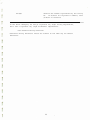
4
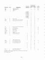
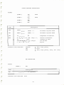
2.
COMMANDS
The fo l lowing key commands halt program execution , erase charac ters or delete
line s .
Explanation
BAS IC 8 0 0 1
CTRL/J or Line Feed
Terminate s program execut ion .
prints READY .
CTRL/M or RETURN
Must be typed to end every l ine typed
in or to indi cate the end of an INPUT .
A colon i s used to s eparate mul t iple
statements per l ine .
CTRL/K or ERASE LINE
Deletes the entire current l ine .
CTRL/L or ERASE PAGE
Era s e s the CRT screen , but doe s not
change or di s turb BAS IC 8 0 0 1 s tatements
i n any way .
CTRL/Z or CURSOR LEFT
Deletes the l a s t character entered and
echoe s a cursor l e f t .
.
The fo llowing c dfumands l is t , load , save , erase and exe cute the program currently
in core .
Explanation
Command
CLEAR
Sets the array and s tring buffers to
nul l s and zeroes .
CLEAR X
Sets space for s tr i ng variable to X
characte rs norma l l y 5 0 characters .
LIST
Prints the user program currently in
core on the l i s t output devi ce .
LIST l ine number
Print s the program from the l ine spec i
fied t o the end.
LOAD I
Does a NEW and inputs the program on track
# I from the READER input device .
LOAD ? I
Doe s not do a NEW but inputs and compares
the program on track # I with what is
existing in RAM Memory.
RUN
Executes the program in the buf fer area .
RUN l ine number
Execute s the program s tarting at l ine
number spe c i fied .
SAVE I
SA'Jt:- 1 LO�D?1.
.'·
.
��-'fy use-�u0
Outputs the program in core to track # I
o f the WRITE output device .
5
-
NEW
Era s e s the entire s torage area .
CONT
Continue s execution a fter CTRL/J i s
typed or a fter a STOP statement.
6
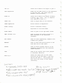
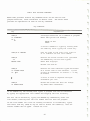
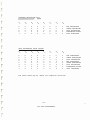
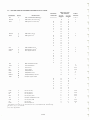
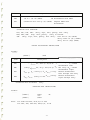
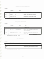
The following functions perform standard mathematical operations in BASIC 8001 .
Name
Explanation
ABS (x)
Returns the absolute value of x .
ATN (x)
Returns the arctangent of x a s an angle
in radians in the range + or - pi/2 .
CALL (x)
COS (x)
TM�
il-{\5 �
t-\U.ST BE:.
POKE.t>
IN
AT
Call the user machine language routine
at location OAOOO HEX . Arf¢tiJ= -2'i576 "".TMP
fl(JI(PI -;!1575"-=- Lo
Returns the cosine of x���ia;�� S7 � �Hr
-2�575 (t.o B�� �""c\- 245'7� (Hi lS�TE.)
:::
Returns the value of e x where e=2 . 7182 8 .
EXP (x)
FRE
(x)
1)0E.S NOT INt\.Ubl:..
INT (x)
fRE-(X�) B':11t.S �
Returns number of free BYTEs not in use .
Returns the greatest integer less than
or equal to x .
INP (x)
Returns a BYTE from input port 0
'LOG (x)
PEEK (x)
�
x
<
255 .
Returns the natural logarithm of x .
3o.rre
o,c;
\)0\( E..
\0 c.�-r; OV\5
Returns a BYTE from memory address O �x 32767
or if X is negative the memory address �
is 65536- x .
•
POS ( x)
Returns a value 0 to 7 9 current cursor
position .
Returns a random number between 0 and 1 .
SGN (x)
Returns a value indicating the sign o f x .
'\ (
SIN (x)
SPC (x)
DISTI':LACiiVe
TAB(x)
Returns the sine of x radians .
Causes x spaces to be generated .
SQR (x)
Returns the square root of x .
TAB (x)
Causes the cursor to tab to column
number x when used in a print statement .
TAN (x)
Returns the tangent of x radians .
7
The string functions are :
Explanation
Name
ASC (x$)
Returns as a decimal number the seven-bit
internal code for the first character of
string (x$ ) .
CHR$ (x)
Generates a one-cha£acter string having the
ASCII value of x .
FRE (x$)
Returns number of free string BYTES .
LEFT$ (x$,I)
Returns left most I characters o f string
(x$ ) .
LEN (x$ )
Returns the number of characters in the
string (x$) .
i>1ID$ ( x$, I , J )
Returns J characters of string (x$)
starting at position I .
RIGHT$ (x$, I )
Returns right most I characters of string
(x$) .
STR$ (x)
Returns the string which represents the
numeric value o f x .
VAL (x$)
Returns the number represented by the string
(x$ ) .
CLEAR X
Re.se.r"es X 'oytes -rot"
betC\ult
"C\\u� is sQ> �oy1es. No s;(\�\e '()put can
excee.� 9" 'lo'fte.cs.
str·m3 d.cx�o..
8
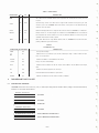
ERROR MESSAGES
After an error occurs , BASIC 8 0 0 1 returns to command level and types
READY . Variable values and the program text remain intact , but the program
cannot be continued and all GOSUB and FOR context is lost .
When an error occurs in a direct statement , no line number is printed .
Format of error messages :
Direct Statement
XX
ERROR
Indirect Statement
XX
ERROR IN
YYYYY
In both of the above examples , " XX " will be the error code . The " YYYYY"
will be the line number where the error occurred for the indirect statement .
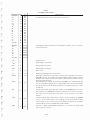
The following are the possible error codes and their meanings :
ERROR CODE
MEANING
BS
Bad Subscript . An attempt was made to reference a
matrix element which is outside the dimension of the
matrix . This error can occur if the wrong number of
dimensions are used in a matrix reference ; for instance ,
LET A ( l , l , l) =Z when A has been dimensioned DIM A ( 2 , 2 ) .
DO
Double Dimension . After a matrix was dimensioned ,
another dimension statement for the same matrix was
encountered . This error often occurs if a matrix has
been given the default dimension 1 0 because a statement
like A (I) =3 is encountered and then later in the program
a DIM A ( lOO ) is found .
CF
Call Function error . The parameter passed to a math
or string function was out of range .
CF errors can occur due to :
a) a negative matrix subscript ( LET A ( -l ) =O)
b) an unreasonably large matrix subscript (>32767 )
c) LOG-negative or zero argument
d) SQR-negative argument
e) A B with A negative and B not an integer .
f) A CALL ( X ) before the address of the machine
language subroutine has been patched in (see�9.7)
g)
calls to MID$ , LEFT$ , RIGHT$ , INP , OUT , WAIT ,
PEEK, POKE , TAB , SPC or ON . . . GOTO with an improper
argument .
9
ID
Illegal Direct . You cannot use an INPUT or DEF
statement as a direct command .
NF
NEXT without FOR. The variable in a NEXT statement
corresponds to no previously executed FOR statement .
OD
Out of Data . A READ statement was executed but all
of the DATA statements in the program have already
been read . The program tried to read too much data
or insufficient data was included in the program .
OM
Out of Memory . Program too large , too many variables ,
too many FOR loops , too many GOSUB ' s , too complicated
an expression or any combination of the above .
ov
Overflow . The result of a calculation was too large
to be represented in BASIC ' s number format . If an
underflow occurs , zero is given as the result and
execution continues without any error message being
printed.
SN
Syntax error . Missing parenthesis in an expression ,
illegal character in a line , incorrect punctuation , etc .
RG
RETURN without GOSUB . A RETURN statement was encountered
without a previous GOSUB statement being executed .
us
Undefined Statement . An attempt was made to GOTO , GOSUB
or THEN to a statement which does not exist .
/0
Division by Zero .
CN
Continue error . Attempt to continue a program when
none exists , an error occurred , or after a new l ine was
typed into the program .
LS
Long String . Attempt was made by use of the concatenation
operator to create a string more than 255 characters long .
OS
Out of String Space . Save your program on paper tape
or cassette , reload BASIC and allocate more string
space or use smaller strings or less string variables .
f\\.\..OCA"f'E. SIRING S'f>ACt
Wl'rl-\
CL.E..AR
X.
5e.� "P5·
r;i!
ST
String Temporaries . A string expression was too complex.
Break it into two or more shorter ones .
TM
Type Mismatch . The left hand side of an assignment
statement was a numeric variable and the right hand
side was a string , or vice versa ; or , a function
which expected a string argument was given a numeric
one or vice versa .
10
UF
Undefined Function . Reference was made to a user
defined function which had never been defined .
11
BASIC 8001 ARITHMETIC
I.
NUMBERS
BASIC treats all numbers (real and integer) as decimal numbers--
that is , it accepts any decimal number and assumes a decimal point
after an integer. The advantage of treating all numbers as decimal
numbers is that any number or symbol can be used in any mathematical
expression without regard to its type . Numbers used must be in the
approximate range lo- 38 <N<lo+3 8 .
In addition to integer and real formats , a third format is recognized
and accepted by BASIC 8001 . This format is called exponential or
E-type notation , and in this format , a number is expressed as a
decimal number times some power of 10 . The form is :
xxEn
where E represents "times 10 to the power of" ; thus the number is
read "xx times 10 to the power of n" . For example :
2 3 . 4E2=23 . 4*l0 2 2340
=
Data may be input in any one or all three of these forms . Results
of computations are output as decimals if they are within the range
. Ol_n_999999 ; otherwise , they are output in E format . Numbers are
stored up to 24 bits of significance . If a number with more than
24 bits is entered , it is truncated and stored as 24 bits . BASIC
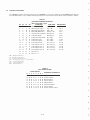
8001 handles six significant digits in normal operation and prints
6 decimal digits as illustrated below :
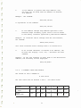
Value Typed In
Value Output by BASIC 8001
. 01
. 0099
999999
1000000
. 01
9 . 90000E -03
999999
l . OOOOOE+06
BASIC automatically suppresses the printing of leading and trailing
zeroes in integer and decimal numbers , and , as can be seen from the
preceding examples , formats all exponential numbers in the form :
( sign) x . xxxxxE (+ or -) n
where x represents the number carried to six decimal places , E stands
for " times 10 to the power of" , and n represents the exponential value .
For example :
-3 . 47021E+08 is equal to -347 , 021 , 000
7 . 26000E-04 is equal to . 00726
Floating point format is used when storing and calculating most numbers .
12
NOTE
Because core size limitations prohibit the storage of
infinite binary numbers , some numbers cannot be expressed
exactly . In BASIC 8001 , accuracy is approximately 5-�
digits , and errors in the 6th digit can occur . For
example , . 999998 as a result of some functions may be
equal to 1 . Discrepancies of this type are magnified when
such a number is used in mathematical operation .
II.
VARIABLES
A variable in BASIC 8001 is an algebraic symbol representing a number , and
i s formed by a single letter , a letter optionally followed by a single
digit or by double letters . For example :
NOTE:
VQ.v- iQ'oles
Mo.y
b�
C\
Acceptable Var1ables
l...t>f'>� "o..r�O\'o\e5
C\�e
ACC.!.PTABL. f.
I
\Jer/ Ll�1u� fol" \r.�e'"""t
B3
d.oCL.h'Y\81'\fQ-t·;O'fl I� 0.
AB
X
=-
stri n� of
8GJlP
.-£.><ci...�'Dt:.S AN�TI-\rNG
W�\Cl-\ r'!.fSt:.fV\6\.tS
A s�s 1c. coMMANI>
ol'IL.'1 2. t..E.FTMoST
otAAACTE.ft5 ARE-
S\Gf'J\F\(;ANT·
D ALE.. -::. ��
chqraders
M ar-.y
t o r"lj
Unacceptable Variables
2C-a digit cannot begin a variable .
11-numbers alone cannot form a
variable .
I
_.1
Subscripted and string variables are described in later sections . The
user may assign values to variables either by indicating the values in
a LET statement , or by inputting the values as data; these operations
are discussed in another chapter .
The value assigned to a variable does not change until the next time a
statement is encountered that contains a new value for that variable .
All variables are set equal to zero ( O ) when the RUN command i s issued .
It is only necessary to assign a value to a variable when an initial
value other than zero is required. However , good programming practice
would be to set variables equal to 0 wherever necessary . This ensures
that later changes or additions will not misinterpret values .
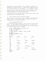
III .
SUBSCRIPTED VARIABLES
In addition to the simple variables described in the preceding section ,
BASIC 8001 allows the use of subscripted variables . Subscripted variables
provide additional computing capabilities for dealing with l ists , tables ,
matrices , or any set of related variables . In BASIC 8001 variables are
allowed from 1 to 31 subscripts .
The name of a subscripted variable is any acceptable BASIC 8001 variable
name followed by one or more integer expressions in parentheses within
the range 0-3276 7 . For example , a list might be described as A ( I) where
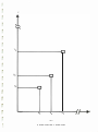
I goes from 0 to 5 as shown below :
A ( O ) , A ( l) , A ( 2 ) , A ( 3 ) , A ( 4 ) ,A ( 5 )
13
This allows reference to each of the six elements in the list , and can
be considered a one dimensional algebraic matrix as follows :
A (O)
A (l)
A (2)
A (3)
A (4)
A (S)
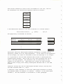
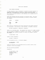
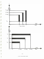
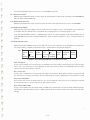
A two-dimensional matrix B ( I , J) can be defined in a similar manner :
B ( O , O) , B ( O , l) , B ( 0 , 2) , .
. , B ( I , J)
. , B ( OJ) , .
and graphically illustrated as follows :
/
B ( 0 , 0)
B ( 1 , 0)
B ( 2 , 0)
B ( 3 , 0)
B (O , l)
B ( l , l)
B ( 2 , l)
B ( 3 , l)
B (0,2)
B (l,2)
B (2 , 2)
B (3 , 2)
B (0 , 3 )
B (l ,3) "
B (2,3) 7
B ( 3 , 3 )7
I B (I ,O)
B (I, l)
B (I, 2)
B ( I , 3 ))
B ( O , J)
B ( l , J)
B ( 2 ,J)
B ( 3 , J)
( B ( I , J)
Subscripts used with subscripted variables throughout a program can be
explicitly stated or be any legal expression . If the value of the expression
is non-integer , the value is truncated so that the subscript is an integer .
It is possible to use the same variable name as both a subscripted and
unsubscripted variable . Both A and A ( I ) are val id variables and can be
used in the same program . The variable A has no relationship to any
element of the matrix A ( I) . BASIC 8001 will accept the same variable
name as both a singly and a doubly subscripted variable name in the same
program .
Character strings may also be subscripted variable arrays , and may have
the same variable name i . e . , A$ ( I) .
A Dimension (DIM) statement is used with subscripted variables to define
the maximum number of elements in a matrix . ( "Matrix" is the subscripted
variable . ) The DIM statement is discussed in a later paragraph .
14
If a subscripted variable is used without appearing in a DIM statement ,
it is assumed to be dimensioned to length 10 in each dimension ( that
is , having eleven elements in each dimension , 0 through 10) . However ,
all matrices should be correctly dimensioned in a program.
IV .
EXPRESSIONS
expression is a group of symbols which can be evaluated by BASIC 8001 .
Expressions are composed of numbers , variables , functions , or a
combination of the preceding separated by arithmetic or relational
operators .
An
The following are examples of expressions acceptable to BASIC 8001 :
String Expressions
Arithmetic Expressions
A$+B$+"ABC"
4
A7* (BI\2+1)
Not all kinds of expressions can be used in all statements , as is
explained in the sections describing the individual statements .
V.
ARITHMETIC OPERATIONS
BASIC 8001 performs addition , subtraction , multiplication , division and
exponentiation . Formulas to be evaluated are represented in a format
similar to standard mathematical notation . The five operators used in
writing most formulas are :
Symbol
Operator
OR
AND
NOT
+
*
I
"
Example
A +
A A *
AI
A 1\
B
B
B
B
B
Meaning
Logical and bitwise "OR"
Logical and bitwise "AND"
Logical and bitwise "NOT"
Add B to A
Subtract B from A
Multiply A by B
Divide A by B
Exponentiation ( Raise A to
the Bth power)
Unary plus and minus are also allowed , e . g . , the - in -A+B or the + in
+X-Y . . Unary plus is ignored . Unary minus is treated as a zero minus
the variable , e . g . , -A+B would be handled as 0-A+B .
VI .
PRIORITY OF ARITHMETIC OPERATIONS
When more than one operation is to be performed in a single formula , as
is most o ften the case , rules are observed as to the precedence of the
operators .
15
In any given mathematical formula , BASIC 8001 performs the arithmetic operations
in the following order of evaluation :
1 . Parentheses receive top priority . Any expression within
parentheses is evaluated before an unparenthesized expression .
2 . In the absence of parentheses , the order of priority is :
�-
Exponentiation (proceeds from left to right). .
b . Unary minus .
c . Multiplication and Division (of equal priority) .
d . Addition and Subtraction (of equal priority) .
e . Logical operators in the order NOT, AND , then OR.
3 . I f either 1 or 2 above does not clearly designate the order of
priority , then the evaluation of expressions proceeds from
left to right .
The expression AABAC is evaluated from left to right as follows :
1 . A/I,B
2.
step 1
( result of step l ) AC = answer
The expression A/B*C is also evaluated from left to right since multi
plication and division are of equal priority :
1 . A/B
2.
step 1
(result of step l ) *C = answer
The expression A+B*CI\D is evaluated as :
1 . CAD
step 1
step 2
2.
( result of step l ) *B
3.
(result of step 2 ) +A = answer
Parentheses may be nested , or enclosed by a second set (or more) of
parentheses . In this case , the expression within the innermost paren
theses is evaluated first , and then the next innermost , and so on , until
all have been evaluated .
In the following example :
A=7* ( (BA2+4 ) /X)
The order of priority is :
16
step 1
2.
( result o f step 1) +4
step 2
3.
( result of step 2 ) /X
step 3
4.
(result of step 3 ) *7 = A
Parentheses also prevent any confusion or doubt as to how the expression
is evaluated . For example :
A*BA.2/7+B/C*DA2
( (A*BA2 ) /7+ ( (B/C) *DA2)
Both of these formulas are executed in the same way , but the second is
easier to understand .
Spaces may be used in a similar manner. Since the BASIC 8001 interpreter
ignores spaces ( except when enclosed in quotation marks) , the two
statements :
1� LET B = DA2 + 1
l�LETB=DA2+l
are identical , but spaces in the first statement provide ease in reading.
When the statement is subsequently printed , extra spaces are ignored .
VII .
RELATIONAL OPERATORS
Relational operators allow comparison of two values and are used to
compare arithmetic expressions or strings in an IF .
THEN statement .
The relational operators are :
Mathematical
Symbol
BASIC 8001,
Symbol
Example
A
(.
B
A is equal to B .
B
A is less than B .
or = <.
A(= B
A is less than or
equal to B .
>
A) B
A is greater than B .
A) = B
A is greater than
or equal to B .
A() B
A is not equal to B .
<
�
(=
>
Meaning
�
>= or =)
'I
<>
A
�'
or)(
<
The symbol s = <, =>
, ) <. are accepted by BASIC 8001 but are converted to
(= , )= , and<.> and are shown in that form in a listing .
17
·l�t"\-�o.�;z� (,0·��. ::cp-l.oyfe po+e.Y\t;Q,J !-eYIJtt
�t-c��rf?��;-G\-f'
01P:��A---\:"� ��r,.��e; t{.... tc;-- tV'l. Gt,.,1 wa.y, t"u:�t �
A\\
\Jo_r-,o..'o\�s
-"'-f-J,;�
o.
Ch""B"- "'"tb C L(f) R X stc.i e me
n
BASIC
CL-Eft� X R€.-S(R.\JE-S
I.
STRINGS
X
8001
STRINGS
'G
see
'6-jT�� Fot<. ST�tNG "DATA
The previous section described the manipulation of numerical information
only; however , BASIC 8 0 0 1 also processes information in the form of
character strings . A string , in this context , is a sequence o f characters
treated as a unit . A string can be composed of alphabetic , numeric , or al
phanumeric characters . (An alphanumeric string is one which contains
letters , numbers , spaces or any combination of characters . ) A character
string can be 255 characters long . Strings cannot be typed on more than
one terminal line since a carriage return terminates the command .
II .
STRING VARIABLES
Any variable name followed by a dollar sign ( $ ) character indicates a
string variable . For example :
A$
C7$
are simple string variables and can be used , for example , as follows :
LET A$="HELLO"
PRINT A$
Note that the string variable A$ is separate and distinct from the variable
A.
In BASIC 8 0 0 1 , all control characters above control code F (or 6) are legal
within Quotes ( " ) except for the following :
Control
Control
Control
Control
III .
Code K or 1 1
Code L or 12
Code M or 1 3
Code z or 26
or
or
or
or
erase line
erase page
return
cursor left
SUBSCRIPTED STRING VARIABLES
Any list of matrix variable name followed by the $ character denotes the
string form of that variable . For example :
V$ (n)
C$ (m,n)
M2$ (n)
Gl$ (m , n)
where m and n indicate the position of the matrix element within the
whole .
The same name can be used as a numeric variable and as a string variable
in the same program with no restriction . A one- and a two-dimensional
matrix can have the same name in the same program . For example :
18
P;)- S'.
-----
A (m , n)
A$ (m, n (
A (n)
A$ (m , n )
A
A$
can a l l b e used i n the same program .
String lists and matrices are defined with the DIM statement as are
numerical lists and matrices .
IV .
STRING OPERATIONS
Concatenation
Concatenation puts one string after another without any intervening
characters . It is specified by a plus sign (+) and works only with
strings . The maximum length of a concantenated string is 255 char
acters .
For example :
1.0 READ A$ , B$ , C$
2.0 DATA " 1 1 " , " 33 " , " 2 2 "
3.0 LET D$ = A$+C$+B$
35 PRINT D$
4.0 END
RUN
1122 3 3
v.
RELATIONAL OPERATIONS
When applied to string operands , the relational operators indicate
alphabetic sequence . The comparison is done on the basis of the ASCI I
value associated with each character in the strings being compared . For
example :
55 IF A$<B$ THEN 100
When l ine 55 is executed , the first characters of each string (A$ and
B$) are compared , then the second characters of each string and so on
until the character in A$ is less than the character in B$ . Then
execution continues at line 100 . Essentially , the strings are compared
for alphabetic order . The next page contains a list of the relational
operators and their string interpretations .
In any string comparison , trailing blanks are ignored ( i . e . , "ABC" is
equivalent to "ABC " ) .
FRE.(x);:;fl\/flll.llBL£
f�E:.(x$)�AVAtL..ABlf.
TelA\...
AVAILABLE.
B'jTES oF PRoG-RAM
B';:\TcS OF
M£MO�j
MEJVlo�j.
Sn�.tNG- M£fv1oRJ.
IS
f=t:.t.(x) + f�£(><�)
19
. ..
co."'
C\clj�..tst � +ro.nrter by CLEIJ� X.
- --- ------
BAS IC
8001
Relational Operators Used With
String Variables
Operator
Example
Meaning
A$ = B$
The strings A$ and B$ are al
phabetically equal .
<
A$ ( B$
The string A$ alphabetically
precedes B $ .
')
A$) B$
The string A $ alphabetically
follows B $ .
(=
or
= (
A$< = B$
The string A $ is equivalent to
or precedes B$ in alphabetical
sequence .
>=
or
=>
A$)= B$
The string
or follows
sequence .
or><
A$() B$
The strings A$ and B$ are not
alphabetically equal .
<)
20
A$
B$
is equivalent to
in alphabetical
BASIC 8001 IMMEDIATE MODE
I . USE OF IMMEDIATE MODE FOR STATEMENT EXECUTION
It is not necessary to write a complete program to use BASIC 8001 .
Most of the statements discussed in this manual can be included in a
program for later execution or given on-line as commands , which are
immediately executed by the 8080 CPU . This latter facility makes
BASIC 8001 an extremely powerful calculator .
BASIC 8001 distinguishes between lines entered for later execution
and those entered for immediate execution solely by the presence (or
absence) of a line number . Statements which begin with l ine numbers
are stored ; statements without line numbers are executed immediately
upon being entered to the system . Thus the line :
1,0 PRINT "THIS IS A COMPUCOLOR 8001 "
produces no action at the console upon entry , while the statement :
PRINT " THIS IS A COMPUCOLOR 8001"
causes the immediate output :
THIS IS A COMPUCOLOR 8001
I I . PROGRAM DEBUGGING
Immediate mode operation is especially useful in two areas : program
debugging and the performance of simple calculations in situations which
do not occur with sufficient frequency or with sufficient complications
to j ustify writing a program .
In order to facilitate debugging a program , STOP statements can be
l iberally placed throughout the program . Each STOP statement causes
the program to halt , at which time the various data values can be
examined and perhaps changed in immediate mode. The
GO TO xxxxx
command is used to continue program execution (where
of the next program line to be executed) . GOSUB and
also be used. The values assigned to variables when
executed remain intact until a NEW , CLEAR or another
executed .
xxxxx is the number
IF commands could
the RUN command was
RUN command is
If the STOP occurs in the middle of a FOR loop , modifications cannot be
made to the section o f the program preceding the FOR.
21
When using immediate mode , nearly all the standard statements can be
used to generate or print results .
If CTRL/J or l inefeed is used to halt program execution , the GO TO XXXX or CONT
command can be used to continue execution , since CTRL J or linefeed
doe s print the number of the line where execution stopped . It is
easy to know where to resume the program.
III . MULTIPLE STATEMENTS PER LINE
Multiple statements can be used on a single line in immediate mode .
For example :
A=l : PRINT A
1
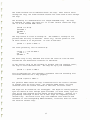
Program loops are allowed in immediate mode; thus a table o f square
roots can be produced as follows :
FOR I=l TO 10 : PRINT I , SQR ( I ) : NEXT I
1
2
3
4
5
6
7
8
9
10
READY
1
1 . 41421
1 . 7 3205
2
2 . 23607
2 . 44949
2 . 64575
2 . 82843
3
3. 16228
IV. RESTRICTIONS ON IMMEDIATE MODE
The INPUT statement cannot be used in immediate mode and such use results
in the following error message :
ID ERROR
READY
Certain commands , while not illegal , make no logical sense when used in
immediate mode . Commands in this category are DEF , DIM and DATA .
Also since user functions are not defined until the program is executed ,
function references in immediate mode cause an error unless the program
containing the definition was previously executed .
Thus , the following dialogue might result if a function was defined in
a user program and then referenced in immediate mode .
10 DEF FNA (X) = XA2 + 2*X : REM SAVED STATEMENT
PRINT FNA (l ) : REM IMMEDIATE MODE
UF ERROR
READY
22
but if the sequence of statements is :
10
RUN
DEF FNA (X)
=
XA2+2*X : REM SAVED STATEMENT
READY
PRINT FNA ( l )
3
READY
the immediate mode statement is executed .
23
BASIC 8001 STATEMENTS
A user program is composed of l ines of statements containing instructions
to BASIC 800 1 . Each line of the program begins with a line number that identi
fies that line as a statement and indicates the order of statement execution .
Each statement starts with an English word specifying the type of operation
to be performed . The statement lines are terminated with the RETURN key
which is non-printing .
I. STATEMENT NUMBERS
An integer number is placed at the beginning of each line in a BASIC 8001
program . BASIC 8001 executes the statements in a program in numerically
consecutive order regardless of the order in which they were typed .
Statement numbers must be within the range 0 to 65529 . When first writing
a program , it is advisable to number lines in increments of five or ten to
allow insertion of forgotten or additional lines when debugging the program.
All BASIC 8001 statements and computations must be written on single line ;
they cannot be continued onto a following line . However , more than one
statement may be written on a single line when each statement after the
first is preceded by a colon ( : ) . For example :
a
1� INPUT A , B , C
is a single statement line , whereas
2� LET X=ll : PRINT
X,Y,Z:
IF
X=A
THEN 1�
is a multiple statement line containing three statements : LET , PRINT , and
IF . Most statements may be used anywhere in a multiple statement l ine ; ,
exceptions are noted in the discussion of each statement . Only the first
statement on a l ine can (and must) have a line number .; It should be re
membered that program control cannot be transferred to'a statement within a
line , but only to the first statement of a line .
I I . REMARK STATEMENT
It is often desirable to insert notes and messages within a user program .
Such data as the name and purpose of the program , how to use it , how
certain parts of the program work , and expected results at various points
are useful things to have present in the program for ready reference by
anyone using that program.
The REMARK or REM statement is used to insert remarks or comments into a
program without these comments affecting execution . Remarks do , however ,
use core area which may be needed by an exceptionally long program .
The REMARK statement must be preceded by a line number and may be used
anywhere in a multiple statement line . The message itself can contain
24
8001
any printing character on the keyboard .
BAS IC
complete l y i gnores
anything on a l ine fol lowing the letters REM .
( The l ine numbe r of a REM
statement c an be used in a GOTO or GOSUB s tatement , see sect ions pertaining
Typical REM s tatements
to destination of a j ump in the program execution . )
are shown be low :
10
11
III .
REM- THIS PROGRAM COMPUTES THE
REM- ROOTS OF A QUADRATIC EQUATION
THE ASS IGNMENT STATEMENT - LET
The LET s tatement a s si gn s a value to the spec ified variable ( s ) .
general format of the LET statement i s :
LET var iable
The
e xpre s s ion
whe re vari able is a numeric or string var iable and e xpre s s ion is an
arithmet i c or string e xpre s s ion . All items in the s ta tement mus t be
either string_or numeric ; they cannot be mixed .
The word LET is optional .
The LET s tatement doe s not indicate algebra ic e qual ity , but performs
calc ulations within the e xpre s s ion ( if any) and a s s i gn s the value to the
variable .
The meaning of the e qual ( = ) s ign should be clarified .
In algebraic
However , in BAS IC
( and
notation , the formula X=X+l i s meaningl e s s .
mos t computer language s ) , the e qual s i gn des ignate s replacement rather
than e qua l i ty .
Thus , thi s formula is actua l l y trans l ated :
"add one to
the c urrent value of X and s tore the new result back i n the s ame variable
Whatever value has previous ly been a s s igned t o X w i l l be combined
X".
An e xpre s s ion such a s A=B+C instructs the computer to
with the value
The
add the value s of B and C and s tore the re sult in a third variable A .
variable A is not being evaluated in terms of any previously a s s i gned value ,
Therefore , if A has been a s s i gned any value
but only in terms of B and C .
prior to i t s use in this s tatement , the old value is los t ; it is i n s tead
replaced by the value B+C .
8001
1.
E xample :
IV .
X-=�=� -::.qg i.s oot e'lQ� u"lect {cr �:.'\8 J ':1 =9SJ 2-=-q� . : Y"ll\1�er; � t ;s
e\laluc:.ted \ o3 ·1 c� lly where, we fest ,f �;:;z::.�g qnc\ C\SS I�:)Y' rQ.S u lf -to X.
.
LET X= 2
As s 1gns the value 2 to the variable X.
LET X=X+l+Y
Adds
to the c urrent value of X then adds the
value of Y to the result and a s s i gn s that value
to X .
1
THE DIMEN S ION STATEMENT - DIM
The DIMen s io n statement i s used to define the maximum numbe r of element s
i n a matr i x .
The DIM s tatement i s of the form :
DIM variable ( n ) ,
variable ( n ,m) ,
variable$ ( n ) ,
variabl e $ ( n , m )
where variables specified are indicated with the ir maximum s ubsc ript value ( s ) .
25
For example :
l� D I M X ( 5 ) I Y ( 4 , 2 ) I A ( l� , 1�)
1 2 DIM A4 ( l�� ) I A$ ( 2 5 )
Onl y integer cons tants ( such as 5 o r 5 0 7 0 ) c an b e used in D I M statements
to de fine the size o f a matrix . Variables cannot be used to spe c i fy the
Any number of matrices c an be de fined in a s i ngle D I M
bounds o f arrays .
s tatement a s long a s the ir repre sentations a r e s eparated b y commas .
The first element o f every matrix i s automatically a s sumed to hav2 .:1 ·:ub
script o f zero.
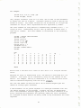
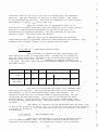
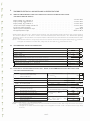
Dimensioning A ( 6 , 1 0 ) sets up room for a matrix with 7
Thi s ze ro element is i llustrated in the fol lowing
rows and l l co lumn s .
program :
l�
2�
3�
4�
5�
6�
7�
8�
9�
RE M - MATRIX CHECK PROGRAM
D I M A ( 6 , 1�)
FOR I=� TO 6
LET A ( I I� )
I
FOR J=� TO l�
LET A ( � , J ) = J
PRINT A(I , J) ;
NEXT J:PRINT : NEXT I
END
RUN
�
l
2
3
4
5
6
1
�
�
�
�
�
�
2
�
�
�
�
�
�
3
�
�
�
�
�
�
4
�
�
�
�
�
�
5
�
�
�
�
�
�
6
�
�
�
�
�
�
7
�
�
�
�
�
�
8
�
�
�
�
�
�
9
�
�
�
�
�
�
1�
�
�
�
�
�
�
READY
Not i c e that a variable has a value of z ero unti l i t i s a s s igned another
value .
Whenever an array i s dimens ioned ( n , m) , the matrix i s allocated m+l , n+l
elements . Core space can be conserved by using the Oth element o f the
matrix .
For example , DIM A ( 5 , 9 ) dimensions a 6 x 1 0 matrix which would
then be re ferenced beginning with the A ( O , O ) element.
The s i z e and number of matrices which can be defined depend upon the
amount of s torage space avai labl e .
A D I M stateme�t can be placed anywhere in a mul tiple statement l ine and
can appear anywhere in the program . A matrix c an only be dimen s ioned
onc e . D I M statements need not appear prior to the first re ference to an
array , although D I M s tatements are generally among the first s tatements
o f a program to allow them to be easily found if any alte rations are l ater
required .
26
All arrays spe cified in DIM s t a t e ments are a llocated spa ce when the RU N
command is exe cu t e d .
V.
PLOT S TATEM ENT
The PLO T S ta t e ment is used t o output the 8 b it BYTE v a lue of an expr e s s ion
The general f or mat of the
t o the CRT S cr e e n .
PLOT S t a t e me n t is :
10 PLOT expre s s ion
The expr e s s ion can be any combinat ion of varia b le s which will eva l uate
t o a p os itive v a lu e be tween 0 and 2 5 5 .
The f ol l owing exa mp le wil l p lot a p oint on the CRT S cr e e n at L ocat ion
80 , 96
10
20
30
40
( X, Y ) :
X=80
Y=96
PLOT 2
REM ARK THE 8001 PLOT MOD E COD E
PLOT X
PLO T Y
PLOT 255
:
REMARK PLOTS POINT AT 80,
As an other exa mp le ente r :
T 71D : P L OT 71
o (,8.. P LOT b� : 1'\.0
f'I..OT�: \'l.OT67: 'I>\. T
PLOI
F1'PJC'tl t. t= G
f,S':
PLOT 6 5
A
�i.� D� � MSIC. 'J)o£.5
READY
It
96
REM AR KS THE 8001 PLOT MOD E ESC APE CODE
can be s ee n that
MOl
(t..F=)(C.RJ S€ !WEEN
( s in ce 6 5 is the de cima l ASC II va lue f or A)
PL.OTS.
PLOT 6 5
is the s a me a s PRI N T "A";
VI.
PRINT S TATEM ENT
The PRINT s tate me n t is u s e d t o output data t o the t e r mina l .
The g e n e r a l
f or ma t of t h e PRINT s tate me nt is :
l)
PRINT lis t
The lis t is
opt ion a l and
can contain expr e s s ion s ,
Whe n u s e d with ou t the lis t ,
2 5 PRINT
;:-"
l:lo�S.
cau s e s a b la n k line t o be
�.,.-
text s t r ing s ,
or b oth .
the PRINT sta te men t :
E'-1\<;.�1 'J"\.ISI S\1:.1� 'S>OvJN •
output on the 8001 CRT S cr e e n
( a car r ia g e r e turn/
line f e e d operat ion is pe r f or med) .
2)
PRINT Expre s s ion
PRINT s tate me n t s can b e u s e d t o per f or m ca lcu lat ions and p r in t r e s u lt s .
Any expre s s ion wit h in the lis t is eva luated b e f or e a va lue is p r in te d .
For e x a mp le :
27
r----- - -
--
1 0 LET A=l : LET B=2 : LET C= 3+A
2 0 PRINT
3 0 PRINT A+B+C
RUN
7
READY
All numbers are printed with a pre ceding and fo l lowing blank spac e .
The PRINT statement c an be used anywhere in a mult iple s tatement l ine .
For example :
1 0 A= l : PRINT A : A=A+S : PRINT : PRINT A
print s the fo l lo wing on the terminal when executed :
l
6
READY
Notice that the terminal per forms a carriage return/l ine feed at the end
Thus the first PRINT sta tement outputs a l and
of each PRINT s tatement .
a carriage re turn/line feed ; the se cond PRINT s tatement the blank l ine ;
and the third PRINT s tatement , a 6 and another carriage return/line feed .
3)
PRINT S trings
The PRINT s tatement c an be used to print a me s s age or string of characters ,
either alone or togethe r with the evaluation and printing o f numer i c value s .
Characters are i ndic ated for print ing by enc los ing them in double quotation
mark s .
For example :
1 0 PRINT " TIME ' S UP "
20 PRINT " NEVERMORE "
RUN
TIME ' S UP
NEVERMORE
READY
As another example , cons ider the fol lowing l ine :
4 0 PRINT " AVERAGE GRADE I S " ; X
which prints the fol lowing ( where X is equal to 8 3 . 4 ) :
AVERAGE GRADE I S 8 3 . 4
28
When a character s tring i s printed , only the characters between the
quotes appear ; no leading or trail ing spaces are added .
Leading and
trail ing spa c e s c an be added within the quotation marks u s ing the key
board space bar ; space s appear in the printout exac tly as they are typed
within the quotation mark s .
When a comma separate s a text str ing from another PRINT l i s t i tem , the
item i s printed at the beginning of the next ava i lable print zone .
Thus ,
S emicolons separat ing text strings from other i tems are ignored .
the previous examp l e could be expre s sed a s :
4 ,0 PRINT " AVERAGE GRADE I S " X
and the same printout would re sul t .
A comma or semic o lon appearing a s
the l a s t i tem o f a PRINT l i s t always suppre s s e s t h e c arriage return/l ine
feed operation .
BAS I C 8 0 0 1 does an automatic carriage return/line feed i f a s tring i s
pr int ing past column 8 0 .
4)
Use o f " , " and " ; "
BAS IC 8 0 0 1 cons iders the 8 0 0 1 CRT S c reen to be divided into ten zon e s o f
eight spaces each .
When a n item in a PRINT s tatement i s fo llowed b y a
comma , the next value to be printed appears in the next ava i l able print
zone.
For example :
1.0 LET A=3 : LET B=2
2 ,0 PRINT A , B , A+B , A* B , A-B , B -A
When the pre c eding l ine s are executed , the fol lowing i s printed :
3
2
5
1
6
-1
Notice each character i s 8 spaces from the next charac te r .
Two commas toge the r in a PRINT s tatement c ause a print zone to be skipped .
For example :
1 .0 LET A=lj LET B=2
2,0 PRINT A , B , , A+B
RUN
1
2
3
READY
I f the l a s t item in a PRINT statement is fol lo wed by a comma , no carriage
return/l ine feed is output , and the next value to be printed ( by a later
PRINT s tatement ) appe ars in the next available print zone .
For example :
29
1 0 A= l : B=2 : C=3
2 0 PRINT A, : PRINT B : PRINT C
RUN
2
l
3
READY
I f a tighter packing o f printed value s is desired , the semicolon
character can be used in place o f the comma. A semicolon cause s no
further spaces to be output other than the leading and tra i l ing space
automatically output with each number . A comma caus e s the print head
to move at least one space to the next print zone or po s s ibly perform
The fol lowing example shows the e ffects
a carriage return/l ine feed .
o f the s emicolon and comma .
1 0 LET A= l/ B=2/ C= 3
2 0 PRINT A ; B ; C ;
3 0 PRINT A+l ; B+l ; C+l
4 0 PRINT A , B , C
RUN
l 2 3 2 3 4
3
l
2
READY
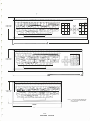
The fol lowing example demons trates the use of the formatting characters ,
and ; with text string s :
1 2 0 PRINT " STUDENT NUMBER" X , " GRADE = " G ; " AVE .
1 3 0 PRINT " NO . IN CLAS S = " N
= "A;
could cause the following to b e printed ( a s sumi ng calculations were done
prior to l ine 1 3 0 ) :
S TUDENT NUMBER 1 1 905 0
5)
GRADE = 8 7 AVE .
8 5 . 4 4 NO . I N CLAS S
26
PRINT S tatement - TAB Function
The TAB func tion is used i n a PRINT statement t o wr ite spaces to the spec
i fied co lumn on the output devi ce.
The co lumn s on the output devic e s are
numbered l to 8 0 .
The form o f the command is :
PRINT TAB ( x )
where ( x ) i s the column number i n the range 0 - 2 5 5.
( I f X exceeds 8 0 ,
however , every other consecutive l ine is tabbed unt il the number o f
spac e s to b e output i s l e s s than or equal to 8 0 ) .
I f the column number
spe c i fied i s greater than 2 5 5 or negative , an error me s s age is printed
as fo llows :
CF ERROR
READY
30
If (x)
used.
i s non- integer , only the integer portion o f the number i s
I f the co lumn number ( x ) speci fied i s l e s s than or equal to the
current column numbe r , the TAB function has no e ffect.
VII .
INPUT STATEMENT
The INPUT s tatement i s used when data i s to be input from the terminal
keyboard during program exe cution. The form of the s tatement i s :
l)
INPUT l i s t
where l i st i s a l i s t o f variable name s separqted by comma s.
For example :
l � INPUT A , B , C
causes the computer to paus e during execution , print a ques tion mark ,
The
and wait for input of three numeric values separated by commas.
value s are input to the computer by typi ng the RETURN key .
If too few values are entered , BAS IC 8 0 0 1 prints another ? to indic ate
that more data i s needed.
I f too many values are typed , the exc e s s
data o n that l ine i s ignored and the me s s age below i s printed but program
s t i l l continues.
The values entered in re sponse to the INPUT s tatement
cannot be continued on another l ine and are terminated by the RETURN
key.
Values mus t be s eparated by comma s , i f more than one value i s
input o n the s ame l ine .
When the re are several value s to be entered via the INPUT s tatement ,
it i s he lpful to print a me s s age explain ing the data needed .
For
example :
l � PRINT " YOUR AGE I S " ;
2 � INPUT A
2)
INPUT " string " ; l i s t
The INPUT statement c a n a l so contain quoted s trings .
could be wri tten :
10
The above example
INPUT " YOUR AGE I S ? " ; A
Note that when a quoted s tring i s inc luded i n a INPUT statement , the
normal ? is not printed as a prompt characte r , and i f de s i red , mus t
be included a s shown within the quote s above .
Thi s feature al lows BAS IC 8 0 0 1 to be programmed to handle f i l l - in-the
forms type of appl ication s .
31
VII I.
DATA STATEMENT
The DATA statement is used in conjunction with the READ statement to
enter data into an executing program . One statement is never used
without the other . The form of the statement is :
DATA value list
where the value list contains the numbers or strings to be assigned to
the variables listed in a READ statement . Individual items in the value
list are separated by commas ; strings must be enclosed in quotation
marks .
For example :
15_0 DATA 4 , 7 . 2 , 3 , "ABC"
17_0 DATA 1 , 34E-3 , 3 . 17311
The location of DATA statements is arbitrary as long as they appear in
the correct order; however , it is good practice to collect all DATA
statements near the end of the program.
When the RUN command is executed , BASIC 8001 searches for the first DATA
statement and saves a pointer to its location . Each time a READ statement
is encountered in the program , the next value in the data statement is
assigned to the designated variable . If there are no more values in that
DATA statement , BASIC 8001 looks for the next DATA statement .
IX.
READ STATEMENT
A READ statement is used to assign the values listed in a DATA statement
to the specified variables . The READ statement is of the form :
READ variable list
The items in the variable list may be simple variable names or string
variable names and are separated by commas . For example :
1_0 READ A , B$ , C ( l)
2_0 DATA 12 , " 12 " , . 12E2
Since data must be read before it can be used in a program , READ statements
generally occur near the beginning of the program . A READ statement can be
placed anywhere in a multiple statement line .
If there is no data available in the data table for the READ to store , the
out o f data message below is printed :
OD. ERROR IN xxxxx
�
/Items
in the data l ist in excess of those needed by the program ' s READ
statements are ignored .
\
32
X . RESTORE STATEMENT
The RESTORE statement causes the program to reuse the data from the
first DATA statement and is of the form :
RESTORE
For example :
3,0 RESTORE
causes the next READ statement following line 30 to begin reading data
from the first DATA statement in the program , regardless of where the
last value was found .
A further example of .the use of RESTORE follows :
15 READ B , C , D
55 RESTORE
6,0 READ E , F , G
8,0 DATA 6 , 3 , 4 , 7 , 9 , 2
1,0,0 END
The READ statements in lines 15 and 60 both read the first three data
values provided in line 80 . ( I f the RESTORE statement had not been
inserted before line 60 , then the second READ would pick up data in
line 80 starting with the fourth value . )
Since the values are being read as though for the first time , the same
variable names may be used the second time through the data , i f desired .
To skip unwanted values , replacement , or dummy , variables may be inserted .
For example :
1 REM - PROGRAM TO ILLUSTRATE USE OF RESTORE
2,0 READ N
2 5 PRINT "VALUES OF X ARE : "
3,0 FOR I=l TO N
4,0 READ X
5,0 PRINT X ,
6,0 NEXT I
7,0 RESTORE
185 PRINT
19,0 PRINT " SECOND LIST OF X VALUES "
2,0,0 PRINT "FOLLOWING RESTORE STATEMENT : "
2 1,0 FOR I=l TO N
22,0 READ X
2 3,0 PRINT X ,
24,0 NEXT I
33
250 DATA 4 , 1 , 2
251 DATA 3 , 4
3 00 END
RUN
VALUES OF X ARE :
l
3
4
2
SECOND LIST OF X VALUES
FOLLOWING RESTORE STATEMENT :
2
4
l
3
READY
The second time the data values are read , the first X picks up the
value originally assigned to N in line 20 , and as a result , BASIC
prints :
4
l
2
3
To circumvent this , a dummy variable could be inserted to pick up and
store the first value . This variable would not be represented in the
PRINT statement , so the output would be the same each time through
the l ist .
XI . GOTO STATEMENT
The GOTO statement is used when it is desired to unconditionally transfer
to some line other than the next sequential line in the program. In
other words , a GOTO statement causes an immediate jump to a specified
line , out of the normal consecutive line number order of execution . The
general format of the statement is as follows :
GOTO line number
The line number to which the program jumps can be either greater or less
than the current line number . It is thus possible to jump forward or
backward within a program .
For example ,
10 LET A=2
20 GOTO 50
30 LET A=SQR (A+l4 )
50 PRINT A , A*A
RUN
causes the following to be printed :
2
4
When the program encounters line 20 , control transfers to line 50 ; line
50 is executed , control then continues to the line following line 50 .
Line 3 0 is never executed . Any number of lines can be skipped in either
direction .
34
When written as part of a multiple statement line , GOTO should always
be the last statement on the line , since any statement following the
GOTO on the same line is never executed . For example :
ll� LET A=ATN (B2) : PRINT A : GOTO 5�
XII . IF-THEN , IF-GOTO STATEMENTS
The IF-THEN statement is used to transfer conditionally from the normal
consecutive order of statement numbers , depending upon the truth of some
mathematical relation or relations . The basic format of the IF statement
is as follows :
THEN
IF expression rel . op . expression
line number
GOTO
where expression is an arithmetic or string expression .
Expressions cannot be mixed ; both must be string
or both must be numeric . Numeric comparisons are
handled as described in the ARITHMETIC Section . String
comparisons are performed on the ASCII values of
the strings as described in the STRING Section .
rel . op .
is one of the operators described in the ARITHMETIC
Section .
line number
is the line of the program to which control is
conditionally passed .
If the value of the expression is true , control passes to the line number
specified .
If the value of the expression
ment in sequence .
lS
false , control passes to the next state
Examples :
l� IF A=B THEN 2� : PRINT "A B"
15 STOP
2� PRINT A+B
l� IF A < ) l� GOTO 2� : PRINT A
15 STOP
2� D=A+B*C
l� IF A$<B$ THEN 2� : STOP
2� PRINT A$
XII I . FOR-NEXT STATEMENTS
FOR and NEXT statements define the beginning and end of a loop . (A loop
is a set of instructions which are repeated over and over again , each time
35
being modified in some way until a terminal condition is reached . )
The FOR statement is of the form :
FOR variable = expressionl TO expression2 STEP expression]
where
variable
must be a nonsubscripted numeric variable .
expression
is an arithmetic expression which may be non
integer .
The variable is the index ; expressionl is the initial value ; expression2 ,
the terminal value and expression] , the increment value .
For example :
15 FOR K=2 TO 2 0 STEP 2
causes the program execution of the designated loop as long as K is
less than or equal to 20 . Each time through the loop , K is incremented
by 2 , so the loop is executed a total of 10 times . When K=20 , program
control passes to the line following the associated NEXT statement .
The index variable must be unsubscripted , although a common use of such
loops is to deal with subscripted variables using the control variable
as the subscript of a previously defined variable . The expressions in
the FOR statement can be any acceptable BASIC 8001 expression .
The NEXT statement signals the end of the loop which began with the
FOR statement . The NEXT statement
of the form :
lS
NEXT variabl�
where the variable is the same variable specified in the FOR statement .
Together the FOR and NEXT statements define the boundaries of the
program loop . When execution encounters the NEXT statement , the computer
adds the STEP expression value to the variable and checks to see i f the
variable is still less than or equal to the terminal expression value .
When the variable exceeds the terminal expression value , control fall s
through the loop to the statement following the NEXT statement . Note
the variable is not necessary since when a NEXT statement is encountered
it is assumed it is for the appropriate FOR loop variable .
If the STEP expression and the word STEP are omitted from the FOR state
ment , +l is the assumed value . Since +l is a common STEP value , that
portion of the statement is frequently omitted .
The expressions within the FOR statement are evaluated once upon initial
entry to the loop . The test for completion of the loop is made after
each execution of the loop . ( I f the test fails initially , the loop is
still executed once . )
36
The index variable can be modified within the loop . When control falls
through the loop , the index variable retains the value used to fall through
the loop .
The following is a demonstration of a simple FOR-NEXT loop . The loop
is executed 10 times ; the value of I is 11 when control leaves the loop ;
and + 1 is the assumed STEP value :
1�
2�
3�
4�
FOR I=l TO 1�
PRINT I
NEXT I
PRINT I
The loop itself is lines 10 through 30 . The numbers 1 through 10 are
printed when the loop is executed . After I=lO , control passes to line
40 which causes 11 to be printed . If line 10 had been :
1� FOR I = 1� TO 1 STEP -1
the value printed by line 40 would be � 1� FOR I = 2 TO 44 STEP 2
2� LET I = 44
3� NEXT I
The above loop is only executed once since the value of I=44 has been
reached and the termination condition is satisfied .
If the initial value of the variable is greater than the terminal value ,
the loop is still executed once . The loop set up by the statement :
1� FOR I = 2� TO 2 STEP 2
will be executed only once although a statement like the following will
initialize execution of a loop properly :
1� FOR I=2� TO 2 STEP -2
For positive STEP values the loop is executed until the control variable
is greater than its final value . For negative STEP values , the loop
continues until the control variable is less than its final value .
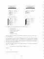
FOR loops can be nested but not overlapped . The depth o f nesting depends
upon the amount of user storage space available ( in other words , upon the
size of the user program and the amount of RAM available) . Nesting is a
programming technique in which one or more loops ar� completely within
another loop . The field of one loop (the numbered lines from the FOR
statement to the corresponding NEXT statement , inclusive) must not cross
the field of another loop .
37
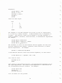
ACCEPTABLE NESTING
TECHNIQUES
UNACCEPTABLE NESTING
TECHNIQUES
Two Level Nesting
�
FOR Il = 1 TO 10
[ FOR I2 = 1 TO 10
NEXT I2
[ FOR I3 = 1 TO 10
NEXT I3
NEXT Il
FOR Il = 1 TO 10
FOR I2 = 1 TO 10
NEXT Il
NEXT I2
Three Level Nesting
FOR I l
FOR I2
[FOR I3 =
NEXT I3
[ FOR I4 =
NEXT I4
NEXT I2
NEXT I l
1 TO 10
1 TO 10
1 TO 10
FOR Il
FOR I2
[FOR I3 =
NEXT I3
[ FOR I4
NEXT I4
NEXT Il
NEXT I2
1 TO 10
=
1 TO 10
1 TO 10
1 TO 10
1 TO 10
An example of nested FOR-NEXT loops is shown below :
5 DIM X ( 5 , 1,0)
1.0 FOR A=l TO 5
2.0 FOR B=2 TO 1.0 STEP 2
3.0 LET X (A , B) = A+B
4.0 NEXT B
5.0 NEXT A
55 PRINT X ( 5 , 1,0)
When the above statements are executed , BASIC 8001 prints 15 when line
55 is processed .
It is possible to exit from a FOR-NEXT loop without the control variable
reaching the termination value . A conditional or unconditional transfer
can be used to leave a loop . Control can only trans fer into a loop which
had been left earlier without being completed , ensuring that termination
and STEP values are assigned .
Both FOR and NEXT statements can appear anywhere in a multiple statement
line . For example :
1.0 FOR I=l TO 1.0 STEP 5 : NEXT I : PRINT " I= " ; I
causes :
I=ll
to be printed when executed .
38
XIV. GOSUB AND RETURN STATEMENTS
A subroutine is a section of code performing some operation required
at more than one point in the program. Sometimes a complicated I/0
operation for a volume of data , a mathematical evaluation which is too
complex for a user-defined function , or any number of other processes
may be best performed in a subroutine .
More than one subroutine can be used in a single program, in which
case they can be placed one after another at the end of the program
( in line number sequence ) . A useful practice is to assign distinc
tive line numbers to subroutines ; for example , if the main program
uses line numbers up to 199 , use 200 and 300 as the first numbers of
two subroutines .
Subroutines are usually placed physically at the end of a program
before DATA statements , if any . The program begins execution and
continues until it encounters a GOSUB statement of the form:
1 ) GOSUB line number
where the line number following the word GOSUB is that of the first
line of the subroutine . Control then transfers to that line of the
subroutine . For example :
5,0 GOSUB 2,0,0
Control is transferred to line 200 in the user program . The first
line in the subroutine can be a remark or any executable statement .
Having reached the line containing a GOSUB statement , control trans
fers to the line indicated after GOSUB ; the subroutine is processed
until BASIC 8001 encounters a RETURN statement of the form :
2 ) RETURN
which causes control to return to the statement following the original
GOSUB statement . A subroutine must always be exited via a RETURN
statement .
Before transferring to the subroutine , BASIC 8001 internally records the
next sequential statement to be processed after the GOSUB statement ;
the RETURN statement is a signal to transfer control to this statement .
In this way , no matter how many subroutines there are or how many times
they are called , BASIC 8001 always knows where to transfer control next .
The following program demonstrates the use of GOSUB and RETURN .
1
1,0
2,0
3 ,0
4,0
REM - THIS PROGRAM ILLUSTRATES GOSUB AND RETURN
DEF FNA (X) = ABS ( INT (X) )
INPUT A , B , C
GOSUB 1,0,0
LET A=FNA (A)
39
5�
6�
7�
8�
9�
1��
11�
12�
13�
14�
15�
16�
17�
18�
185
19�
2��
2�5
2�7
21�
9��
LET B=FNA (B)
LET C=FNA (C)
PRINT
GOSUB 1��
STOP
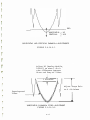
REM - THIS SUBROUTINE PRINTS OUT THE SOLUTIONS
REM - OF THE EQUATION : AXA2 + BX + C = �
PRINT "THE EQUATION IS "A " *XI\2 + B"*X + "C
LET D=B*B - 4 *A*C
IF D<)O THEN 17�
PRINT " ONLY ONE SOLUTION . . . X " -B/ ( 2 *A)
RETURN
IF D(� THEN 2��
PRINT " TWO SOLUTIONS . . . X = " ;
PRINT ( -B+SQR (D) ) / ( 2*A) ; " ) AND ( " ; ( -B-SQR (D) ) / ( 2 *A)
RETURN
PRINT " IMAGINARY SOLUTIONS . . . X= ( " ;
PRINT -B/ ( 2 *A) " , " SQR ( -D) / ( 2 *A) " ) AND ( " ;
PRINT -B/ ( 2 *A) " , " ; -SQR ( -D) / ( 2*A) " ) "
RETURN
END
II
Subroutines can be nested ; that is , one subroutine can call another
subroutine . If the execution of a subroutine encounters a RETURN
statement , it returns control to the line following the GOSUB which
called that subroutine . Therefore , a subroutine can call another
subroutine , even itself . Subroutines can be entered at any point
and can have more than one RETURN statement . I t is possible to trans
fer to the beginning or any part of a subroutine ; multiple entry points
and RETURN ' s make a subroutine more versatile . Up to 20 levels of
GOSUB nesting are allowed .
X.V . END STATEMENT
'The END statement is the last statement in a BASIC program and is of
the form :
END
The line number of the END statement must be the largest line number
in a given program , since any lines having line numbers greater than
that of the END statement are not executed ( although they are saved
with the SAVE command) .
The END statement is optional . When an END statement is executed ,
program execution stops ahd the READY message is printed .
X.VI . STOP STATEMENT
The STOP statement can occur several times throughout a single program
with conditional j umps determining the actual end of the program . The
STOP statement is of the form :
90 STOP
40
and causes :
BREAK IN 90
READY
to be printed when executed .
This signals that the execution of a program has been terminated and
BASIC 8001 is able to accept further input .
41
BASIC 8001 FUNCTIONS
ARITHMETIC FUNCTIONS
BASIC 8001 provides functions to perform certain standard mathematical
operations such as square roots , logarithms , etc .
These functions have three or four letter call names followed by
a parenthesized argument . They are pre-defined and may be used
anywhere in a program .
Function
Call Name
ABS (x)
Returns the absolute value of x .
ATN (x)
Returns the arctangent o f x a s an
angle in radians in range + or -pi/2 .
CALL (x)
CALL the user , machine lan g�age pro �ram
. 0A000 Hex . AfP<I{J - 'SI'\ V -_ -2L\!> 7b
at locatlOn
ACPrP I Lo
-2 "\ 5'7
::.
:;
5
M�i!.. " 1-1� = - 2."\ 57 1.\
COS (x)
Returns the cosine of x radians .
EXP (x)
Returns the value o f eX where e=2 . 71828 .
FRE (x)
Returns number of free BYTES not in use .
INT (x)
Returns the greatest integer less than
or equal to x , ( INT ( - . 5 ) =-l) .
INP (x)
Returns a BYTE from input port O<x(255 .
LOG (x)
Returns the natural logarithm of x .
PEEK (x)
Returns a BYTE from memory address �x�32767
or if x is negative the memory address is
65536i'X .
POS (x)
Returns a value of current cursor positions
between 0 and 79 .
RN D
( x)
SGN (x)
qJt\e(
l(\'\0 n i.-' M\,e,("f1,
�o\ -roo c;.oo\)
Gf'o\'j
.
..
V..X.��\\\�
Returns a random number between 0 and l .
Returns a value indicating the sign o f x .
SIN (x)
Returns the sine o f x radians .
SPC (x)
Causes x spaces to be generated .
SQR (x)
Returns the square root of x .
TAB (x)
Causes the 8001 CRT to space over to column
number x . Valid in PRINT statement only .
TAN (x)
Returns the tangent of x radians .
42
-
The argument x to the functions can be a constant , a variable , an
expression , or another function . A square bracket cannot be used as
the enclosing character for the argument x , e . g . SIN [x] is illegal .
Function calls , consisting of the function name followed by a paren
thesized argument , can be used as expressions or as elements of
expressions anywhere that expressions are legal .
Values produced by the functions SIN (x) , COS (x) , ATN (x) , SQR (x) , EXP (
and LOG (x) have six significant digits .
I.
Sine and Cosine Functions , SIN (x) and COS (x)
The sine and cosine functions require an argument angle expressed in
radian measure . If the angle is stated in degrees , conversion to
radians may be done using the identity :
(radians>
(degrees) * (pi/180)
In the following example program, 3 . 14159 is used as a nominal value
for pi . P is set equal to this value at line 20 . At l ine 40 the
above relationship is used ( in the expression within the LET statemer
to convert the input value into radians .
1 0 REM - CONVERT ANGLE (X) TO RADIANS , AND
ll REM - FIND SIN AND COS
20 LET P = 3 . 14159
25 PRINT "DEGREES " , "RADIANS " , "SINE " , "COSINE"
3 0 INPUT X
4 0 LET Y = X*P/180
60 PRINT X , Y , SIN (Y) , COS (Y)
70 GOTO 30
RUN
COSINE
SINE
RADIANS
DEGREES
?0
l
0
0
0
?10 ·
. 173648
. 984808
. 174533
10
?20
. 939693
. 34202
. 349066
20
?30
. 866026
.5
. 52 3598
30
?360
6 . 28318
-5 . 24310E-06 l
360
?45
. 707107
. 785398
. 707106
45
?90
l . l2352E-06
l
l . 5708
90
?RETURN
READY
43
Arctangent Function , ATN (x) ; 'l'angent Function , TAN (x)
II .
The arctangent function returns a value in radian measure , in the range
+pi/2 to -pi/2 corresponding to the value of a tangent supplied as the
argument (X) .
In the fol lowing program , input is an angle in degrees . Degrees are
then converted to radians at line 40 .
At line 70 the tangent value , Z , is supplied as argument to the ATN
function to derive the value found in column 4 of the printout under
the label ATN (X) . Also in line 70 the radian value of the arctangent
function is converted back to degrees and printed in the fifth column
of the printout as a check against the input value shown in the first
column .
1� LET P= 3 . 14159
2� PRINT "SUPPLY AN ANGLE IN DEGREES "
25 PRINT "ANGLE" , "ANGLE" , "TAN (X) "ATAN (X) "ATAN (X)
26 PRINT " (DEGS) " , " (RADS ) " , , , " (DEGS) "
3� INPUT X
4� LET Y = X*P/18�
5� LET Z = TAN (Y)
7� PRINT X , Y , Z ,ATN ( Z ) ,ATN (Z) *l80/P
85 PRINT
9� GOTO 3�
RUN
SUPPLY AN ANGLE IN DEGREES
ATAN (X)
ATAN (X)
TAN (X)
ANGLE ANGLE
(DEGS )
(DEGS ) (RADS )
?�
�
�
�
II ,
?45
45
III .
II ,
. 785398
. 999999
. 785398
45
?1�
. 174533
10
? ( RETURN)
READY
. 176327
. 174533
1�
I
I
Square Root Function , SQR (x)
This function derives the square root of any positive value as shown
below.
1.0 INPUT X
2� LET X SQR (X)
3� PRINT X
4� GOTO 1�
RUN
? 16
4
?1.0�
1�
?1���
44
31 . 6228
?12 3456789
11111 . 1
?17
4 . 12311
?25E2
50
?1970
44 . 3847
? (RETURN)
READY
IV.
Exponential Function , EXP (x)
The exponential function raises the number e to the power x . EXP is
the inverse of the LOG function . The relationship is
LOG ( EXP (X) ) = X
The following program prints the exponential equivalent of an input
value . Note that the output values derived below are used as input to
.the LOG function .
1 0 INPUT X
20 PRINT EXP (X)
40 GOTO 1 0
RUN
?4
54 . 5981
?10
22026 . 5
?9 . 421006
12345
?4 . 60517
1 00
?25
7 . 20049E+l0
? ( RETURN)
READY
V.
Logarithm Function , LOG (x)
The LOG function derives the logarithm to the base e of a given value .
In the following program at line 20 , the LOG function is used to
convert an input value to its logarithmic equivalent .
1 0 INPUT X
2 0 PRINT LOG (X)
30 GOTO 10
RUN
?54 . 598 15
4
?22026 . 47
10
45
?12345
9 . 42101
?100
4 . 60517
? . 720049Ell
25
? (RETURN)
READY
Logarithms to the base e may easily be converted to any other base
using the following formula :
where a represents the desired base . The following program illustrates
conversion to the base 10 .
l REM - CONVERT BASE E LOG TO BASE 10 LOG .
5 PRINT "VALUE" , "BASE E LOG" , "BASE 10 LOG"
15 INPUT X
17 PRINT X ,
20 PRINT LOG (X) ,
40 PRINT LOG (X) /LOG ( l0)
50 GOTO 15
60 END
RUN
BASE lfO LOG
BASE E LOG
VALUE
?4
1 . 38629
4
. 60206
?250
5 . 52146
2 . 39794
250
?5
1 . 6 0 944
5
. 69897
?60
l . 77815
4 . 09434
60
?100
4 . 60517
2
100
? (RETURN)
READY
attempt to do a LOG ( O) or LOG of a negative number causes the
CF error message .
An
VI .
Absolute Function , ABS (x)
The ABS function returns an absolute value for any argument value .
Absolute value is always positive . In the following program, various
input values are converted to their absolute values and printed .
46
lYJ' INPUT X
2YJ' LET X ABS (X)
3YJ' PRINT X
4YJ' GOTO lYJ'
'RUN
?-35 . 7
35 . 7
?2
2
?25ElYJ'
2 . 5YJ'YJ'YJ'YJ'E+11
?lYJ'5555567
l . YJ'5556E+YJ'8
?lYJ' .. 12345
10 . 1234
?-44 . 555566668899
44 . 5556
? (RETURN)
READY
VII .
Integer Function , INT (x)
The integer function returns the value of the greatest integer not
greater than x . For example :
PRINT INT ( 34 . 67 )
34
PRINT INT ( -5 . 1)
-6
The INT of a negative number is a negative number with the same or
larger absolute value , i . e . , the same or smaller algebraic value .
For example :
PRINT INT (-23 . 45)
-24
PRINT INT ( -14 . 39 )
-15
PRINT INT ( -11)
-11
The INT function can be used to round numbers to the nearest integer ,
using INT (X+ . 5 ) . For example :
PRINT INT ( 34 . 67+ . 5)
35
PRINT INT (-5 . 1+ . 5 )
-5
47
INT (x) can also be used to round to any given decimal place or
integral power of 10 , by using the following expression as an
argument :
(X*lOtD + . 5 ) /lO D
where D is an integer supplied by the user .
l� REM - INT FUNCTION EXAMPLE
15 PRINT
2� PRINT "NUMBER TO BE ROUNDED :
25 INPUT A
4� PRINT "NO . OF DECIMAL PLACES : "
45 INPUT D
6� LET B INT (A*lOAD + . 5) /l�A D
7� PRINT "A ROUNDED
B
8� GOTO 15
9� END
RUN
II
=
=
II
NUMBER TO BE ROUNDED :
?55 . 65842
NO . OF DECIMAL PLACES :
?2
A ROUNDED 55 . 66
=
NUMBER TO BE ROUNDED :
?78 . 375
NO . OF DECIMAL PLACES :
?-2
A ROUNDED l��
=
NUMBER TO BE ROUNDED :
?67 . 38
NO . OF DECIMAL PLACES :
?-1
A ROUNDED 7�
=
NUMBER TO BE ROUNDED :
? (RETURN)
READY
VII I .
Random Number Function , RND (x)
The random number function produces a random number , or random number
set , between 0 and l . The numbers are reproducible in the same order
after ESC , E key i f X�O for later checking of a program . The argument (x)
is not used and can be any n��er ( it cannot be a string expression) ; it
serves only to standardize all BASIC 8001 function representations . The
form RND is not legal . For example :
48
10 REM - RANDOM NUMBER EXAMPLE .
25 PRINT "RANDOM NUMBERS :
30 FOR I l TO 15
40 PRINT RND ( l) ;
50 NEXT I
60 END
RUN
RANDOM NUMBERS :
. 1002 50 . 50438 . 964813 . 0267824 . 886627 . 388094 . 636444 . 56912 3 . 839019 . 720021
. 306121 . 209046 . 285553 . 599886 . 958221 . 744055 . 1793 5 1 . 460434 . 452117 . 433291
. 985412 . 27376 . 522186 . 701146 . 246246 . 590584 . 777801 . 45 7448 . 450592 . 30797
=
READY
To obtain random digits from 0 to 9 , change line 40 to read :
40 PRINT INT ( lO*RND ( l ) ) ,
and run the program again . This time the results will be printed
as follows :
RUN
RANDOM NUMBERS :
8
9
5
4
8
4
9
l
5
5
5
5
9
8
READY
It is possible to generate random numbers over a given range . I f
the open range (A , B) i s desired , use the expression :
(B-A) *RND ( l ) +A
to produce a random number in the range A<n<B .
The following program produces a random number set in the open range
4 , 6 ( the extremes , 4 and 6 , are never reached) .
10
20
30
40
50
60
REM - RANDOM NUMBER SET IN OPEN RANGE 4 , 6 .
FOR B l TO 15
LET A ( 6-4 ) * RND ( l) +4
PRINT A,
NEXT B
END
=
=
RUN
4 . 20054 . 59266 5 . 929624 . 20985 5 . 773255 . 54026 5 . 272884 . 76248 5 . 678045 . 25946
4 . 612245 . 33046 4 . 571104 . 26695 5 . 916445 . 69965 4 . 358705 . 54721 4 . 904235 . 65021
4 . 197085 . 09034 5 . 044374 . 82533 4 . 492495 . 61408 5 . 555604 . 41632 4 . 901185 . 01508
READY
49
7
NOTE : Negative arguments , i . e . , RND ( -x) will start a new random
number sequence . While RND (0) will always generate the last random
number . RNl>(-x) w ; lj o.\w"y s re�-\-�rT the S <l\ M � r � t'\ d o m 1'\LA VVI� r s e,tueY) c e !
IX.
Sign Function , SGN (x)
The sign function returns the value 1 if x is a positive value , 0
i f x is 0 and -1 if x is negative . For example :
PRINT SGN ( 3 . 42 )
1
PRINT SGN ( -42 )
-1
PRINT SGN (23-2 3 )
0
The following example program illustrates the use of the SGN function .
10 REM-SGN FUNCTION EXAMPLE .
20 READ A , B , C
2 5 PRINT " A = "A , " B = "B , " C = "C
W PRINT "SGN (A) ="SGN (A) , "SGN (B) ="SGN (B) ,
40 PRINT "SGN (C) ="SGN (C)
5 0 DATA -7 . 32 , . 44 , 0
60 END
RUN
A = -7 . 32 B = . 44 C = 0
SGN (A) =-1 SGN (B) =1 SGN (C) =0
READY
X.
Call Statement
The CALL statement can be inserted anywhere in the BASIC 8001 program
and has the form :
CALL (expression)
Where
is the argument to the assembly
language routine . The argument
may be an expression . This may
include values passed to the use1
routine .
expression
The CALL statement causes a j ump to location AOOO HEX , which , unless
modified by the user , contains a jump to the CF ERROR routine . The
user must modify these three locations to go to his routines .
50
BASIC 8001 FUNCTIONS
USER DEFINED FUNCTIONS
In some programs it may be necessary to execute the same sequence of
statements or mathematical formulas in several different places .
BASIC 8001 allows definition of unique operations or expressions and
the calling of these functions in the same way as the square root or
trig functions .
These user-defined functions consist of a function name : the first
two letters of which are FN followed by a third or a fourth letter .
For example :
legal
illegal
FNA
FNAA
FNAl
FNA$
FN2
Each function is defined once and the definition may appear anywhere
in the program . The defining or DEF statement is formed as follows :
DEF FNa ( argument)
=
expression (argument)
where a is a variable name . The argument may consist of a dummy variable
and the number of arguments is l imited to one variable . The expression
may contain other program variables not among the argument variable .
For example :
10 DEF FNA ( S ) = SA2
causes a later statement :
2� LET R = FNA (4 ) +1
to be evaluated as R=l7 . As another example :
5� DEF FNB (A) = A+XA2
6� Y=FNB ( l4 )
causes the function to be evaluated with the current value o f the
variable X within the program.
The two following programs
Program #1 :
l�
2�
3�
4�
5�
DEF FNS (A) = AAA
FOR I=l TO 5
PRINT I , FNS ( I )
NEXT I
END
51
Program #2 :
l�
2�
3�
4�
5�
DEF FNS (X) = XI\X.
FOR I=l TO 5
PRINT I , FNS ( I)
NEXT I
END
cause the same output :
RUN
l
2
3
4
5
l
4
27
256
3125
READY
The argument in the DEF statement can be seen to have no significance ;
it is strictly a dummy variable . (A DEF statement with no arguments is
illegal . ) The function itself can be defined in the DEF statement in
terms of numbers , variables , other functions , or mathematical expressions .
For example :
l� DEF FNA (X)
2� DEF FNB (X)
3� DEF FNC (X)
XI\2+3*X+4
FNA (X) /2 + FNA (X)
SQR ( X+4) +l
The statement in which the user-defined function appears can have that
function combined with numbers , variables , other functions , or mathe
matical expressions . For example :
4� LET R = FNA (X+Y+Z) *N/ (YA2+D)
A user-defined function cannot have several arguments , as shown below :
25 DEF FNL (X , Y , Z) = SQR (X� + YA2 + ZA2 )
will cause an error
SN ERROR IN 25 .
READY
When calling a user-defined function , the parenthesized arguments can be
any legal expressions . The value of each expression is substituted for
the corresponding function variable . For example :
l� DEF FNZ (X) =XA2
2� LET A=2
3� PRINT FNZ ( 2+A)
line 30 causes 16 to be printed .
52
If the same function name is defined more than once , then the last
definition will be used . The program below
l�
2�
3�
4�
DEF FNX ( X) =XA2
DEF FNX ( X) =X+X
LET A=5
PRINT FNX (A)
will cause 10 to be printed .
The function variable need not appear in the function expression as
shown below :
10 DEF FNA (X) 4 +2
20 LET R FNA ( lO) +l
30 PRINT R
40 END
RUN
7
=
53
BASIC 8001 FUNCTIONS
STRING FUNCTIONS
Like the intrinsic mathematical functions (e . g . , SIN , LOG) , BASIC 8001
contains various functions for use with character strings . These
functions allow the program to concatenate two strings , access part of
a string , determine the number of characters in a string, generate a
character string corresponding to a given number or vice versa , search
for a substring within a larger string , and perform other useful
operations . The various functions available are summarized in the
following table .
String Functions
Meaning
Function code
ASC (x$ )
Returns the seven-bit internal code for the
one-character string (x$) as a decimal num
ber . If the argument contains more than
one character , then the first character in
the string is returned .
CHR$ (x)
Generates a one-character string having the
ASCII value of x where x is a number greater
than or equal to 0 and less than or equal to
255 . For example : CHR$ (65) is equivalent
to "A" . Only one character can be generated .
FRE (x$)
Returns number of free string BY', , .
LEFT$ (x$ , I)
Returns left most I characters of string
(x$ ) .
LEN (x$)
Returns the number of characters in the
string x$ ( including trailing blanks ) . For
example :
PRINT LEN (A$ )
26
MID$ (x$ , I , J)
Returns the string of characters in position
I through J in x$ .
RIGHT$ (x$ , I)
Returns right most I characters of string
(x$ ) .
STR$ (x)
Returns the string which represents the
numeric value of x as it would be printed by
a PRINT statement but without a leading or
trailing blank .
54
VAL ( x $ )
Re turn s the numbe r r e p r e s ented by the s t r i ng
x$ .
I f x$ does not repr e s ent a numb e r ,
� �alue i s returned .
In the above exampl e s , x $ and y $ r e pre sen t any l egal s t r i n g e xpr e s s i on s ,
and I and J r epre s ent any legal a r i thmet ic expr e s s i o n s .
U s e r - D e f i n e d S t r ing Fun c t i on s
Cha r a c te r s t r ing fun c t i o n s c an not b e written i n the same way a s nume r i c
func t i o n s .
'·
55
then
BASIC 8001 EDITING COMMANDS
BASIC 8001 provides several key commands which can be used to halt
program execution , erase characters or delete lines . The below table
provides an explanation of each of the key commands .
Key Commands
Key
CTRL/J
or LINEFEED
or -1-
Explanation
Interrupts execution of a command or program .
BASIC 8001 prints the message
BREAK IN XXX
READY
A control command is typed by holding down
the CTRL key while typing the letter key .
CTRL/M or RETURN
Must be typed to end every line typed in
or to indicate the end of an INPUT .
CTRL/K
·or
ERASE LINE
Deletes the entire current line (provided
the RETURN key has not been typed) .
BASIC 8001 displays :
Erased line and CR.
CTRL/Z
or CURSOR LEFT
or (:--
Deletes the last character typed and echoes
as a cursor left on the terminal . Snaces
as well as characters or control cc .es may
be erased .
A colon is used to separate multiple
statements per line .
CTRL/L
or ERASE PAGE
Erases CRT screen but does not change
any BASIC 8001 statements .
If the RETURN key has already been typed , a program line can be corrected
by typing the appropriate line number and retyping the line correctly .
The line can be deleted by typing the RETURN key immediately after the
line number ; removing both the line number and line from the program.
If the line number of a line not needing correction is accidentally typed ,
the cursor left key (CTRL Z ) may be used to delete the number ( s ) ; then the
correct number can be typed . Assume the line :
56
l� IF A>5 GO TO
23�
is correct . A l ine 15 is to be inserted , but :
l� LET
is typed by mistake . The correction is made as follows :
l� LET� .. + 4-5 LET X=X-3
Line 10 remains unchanged , and line 15 is entered .
Following an attempt to run a program , error messages may be output
on the terminal indicating illegal characters or formats , or other
user errors in the program. Most errors can be corrected by typing
the l ine number ( s) and the correction ( s ) and then rerunning the pro
gram. As many changes or corrections as desired may be made before
runs .
The following editing commands are entered in immediate mode and
terminated by the RETURN key . These commands are used to erase a
program in RAM , and list , punch or run a program .
I.
NEW COMMAND
The NEW command clears current contents of the storage area set up
by BASIC 8001 . This deletes any commands , programs , arrays , strings
or symbol s currently stored by BASIC 8001 .
NEW should be used before entering a new program from the terminal
keyboard to be sure no old program lines will be mixed into the new
program and to clear out the symbol table area .
Example :
NEW
READY
l� READ A
clears the storage area and inserts the program being input at the
keyboard.
II.
LIST COMMAND
The , LIST command prints the user program currently in core on the
terminal .
A part of a program may be listed by typing LIST followed by a l ine
number . This causes that line and all following l ines in the program
to be listed .
57
Type CTRL/J or linefeed key to halt the listing . BASIC 8001 returns
to the READY message when the current line is finished .
The lines listed may differ slightly from those entered because :
l . Certain characters while acceptable to BASIC 8001 are stored
in a standard manner .
Character
Typed
=(
=>
> (
Character
Stored
<=
>=
< >
2 . Literals are stored to 24 bits of accuracy . Those with more
than 24 bits are truncated to 24 bits .
3 . Although literal storage is 24 bits , output is truncated to
6 decimal digits .
4 . Literals are output in standard BASIC 8001 format , regardless of
how they were input ; for example ,
10 LET X=3 . 0+1 . 000000l
20 PRINT X-E7
LIST
10 LET X=3+l
2 0 PRINT X-l . 00000E+07
5 . Spaces in the input program are ignored , except within
strings and REM statements . The LIST command prints the
program with a space inserted to separate the key word and
the line number . The listed program is therefore easier
to read .
Example :
LIST 100
Lists line 100 and all remaining lines in the program .
III .
.SAVE COMMAND
The SAVE command outputs the program in RAM to the specified device .
The form of the command is :
SAVE A
The format of the program output by the SAVE command is exactly the
same as that stored in RAM memory . It may be recalled by the same
file name using the LOAD command .
58
IV.
RUN COMMAND
After the user program is entered into
typing the command
RAM ,
it can be executed by
RUN
and the RETURN key .
The program is scanned ; arrays are created in core and then the program
is executed . Any appropriate error messages are printed and when the
END or STOP statement is encountered , execution halts and a message is
printed .
After execution , the variables used in a program remain accessible for
use in immediate mode until a NEW, CLEAR or another RUN command is
executed .
V.
CLEAR COMMAND
The CLEAR command clears the contents of the user array and string
buffers . This command is generally used when a program has been exe
cuted and then edited . Before it is rerun , the array and string buffers
are set to zeros and nulls by the CLEAR command to provide more core .
These buffers will be filled again when the RUN command is executed .
Example :
ljO A=ljO
2j0 PRINT A
CLEAR
READY
RUN
ljO
READY
VI .
CLEAR X COMMAND
The CLEAR X performs the same function as CLEAR without the argument ,
but the Argument X reserves X locations for string variables which are
required in string calculations . Normally this is 50 locations unless
changed by CLEAR X command .
VII .
CONTINUE COMMAND
Continues program execution after a Control J or l ine feed is typed or
a STOP statement is executed . You cannot continue after any erro4 after
modifying your program or before your program has been run .
59
One of the main purposes of CONT is debugging . Suppose at some point
qfter running your program , nothing is printed . This may be because
your program is performing some time-consuming calculation , but it may
be because you have fallen into an " infinite loop" . An infinite loop
is a series of BASIC 8001 statements from which there is no escape .
The BASIC 8001 will keep executing a series of statements over and
over until you intervene or until power to the unit is cut off . I f
you suspect your program is in an infinite loop , type in a Control J
or l ine feed . The line number of the statement BASIC 8001 was executing
will be typed out .
After BASIC 8001 has typed out READY , you can use PRINT to type out
some of the values of your variables . After examining these values ,
you may become satisfied that your program is functioning correctly .
You should then type in CONT to continue executing your program where
it left off , or type a direct GOTO statement to resume execution of
the program at a different line .
You could also use assignment (LET) statements to set some of your
variables to different values . Remember , if you line feed or Control
J your program and expect to continue it later , you must not get any
errors or type in any program lines . If you do , you won ' t be able to
continue , and get a "CN" ( continue not) error . It is impossible to
continue a direct command . CONT always resumes execution at the next
statement to be executed in your program when Control J or line feed
was typed .
VII I .
LOAD I COMMAND
LOADS the program named I f�om the 8001 CPU operating system Reader
Input port speci fied by the I/0 BYTE at location 9F90 HEX , see the
CPU O . S . Manua l . A new command is automatically done before the
LOAD I command is executed . When finished loading the READY command
will appear as usual . I f the unit can ' t find the file on the floppy
tape , then an error message should appear .
IX .
LOAD? I COMMAND
Does same as LOAD I except that a NEW command is not performed and
BASIC 8001 does a word-by-word comparison of file I with the program
already existing in RAM memory . If they are the same , then READY
appears , else
VERIFY FAILURE
READY
will appear .
This should always be used after saving a program with the SAVE I
command to ensure that it was saved correctly and can be reloaded
without error .
60
.
. ........ . .
.
..
....
, ....... .
... · ·- ·· -
USING ASSEMBLY LANGUAGE
ROUTINES WITH BASIC
BASIC 8001 has a facility which allows experienced 8080 assembly
language programmers to interface their own assembly language
routines to BASIC 8001 . This facility permits the user to add
functions to BASIC 8001 which can operate directly on special
purpose peripheral devices . This section describes in some detail
the internal characteristics of BASIC 8001 during the execution of
a BASIC 8001 program , and is intended to serve as a programming
guide for the creation of such user-coded assembly language functions .
This material assumes the user is familiar with 8080 assembly
language . For additional information on this subj ect , refer to an
assembly language programming manual on the 8080 CPU .
The CALL statement is used to reference these assembly language
routines from the BASIC 8001 program.
h'�se rn b ly L n n�r-• n �) e.
,-,nJ ?Ci � S o. c � 1.1 e m e ni.s .
lo
call
left) )!b '1"'.,\ �<loo .-lo,<- , by iecD
, 'to fhe
nns ; c t> co�c � ""-' (M" I t :r ly X �� 2, "'t , h JI.�
J (f) .Ii\J P <A T X
2f!) /1 -: CA LL (X)
J'l(�
{llt•IE3<Zl ? g 1 N ·:;- X, 19
.
,
,--.
--.
Lj(J) &o TO if/J
§" r-vt<f!. - 2L45 759 ¢ : po ;< e.. - 2� 5 7 4 ;� I 'J b
f)SS£M B L :) t.. /1/ll& i.-1/J&E.. PRCXJf-.�
)-_�;}pi
CALL
Mo V
2 5AEr�
Ai
£
Rtc:
M Di.J 8 11
X P. (}
� G �.'t- X ·, .,
·D,£
f�o:'V'J \3/3 S tC
p ·-- .:. :r • ct •'"n
:
AT �-.oGATi D I'>J 2� f> 2 ,-i E..� . I.AJ ·, I I
"�'\"'-'<! c:f X' ; fit,� ThO!. '!), E. rej ' .ste r.
CA i..L u\! G-
�..:l't -+1-.�
.
I
R.:. ,J: std ,-.
'
11
.J"M P 2C 53 H
\
-
-
My ·t e ·J r �cr�
J @
2{])
Po l< t
IN
P l-i\
- 24 5 751 ¢ :
>(
3 (1) F oR I � i 10 l lP lPW
y (D
Fo r� I -:: I 10
q9
E N1)
s-q; GoTo 2Jb
B CPCP(])
Ba>CP 3
''PJ (lJ(P '1
B <P(£)5
•·
i ebCPIJ ;
P o i< E.
f} ;: Cf) t.L (.x} N £ KT ,'
A :: 2 �(x ) : N IZ- .XT
·
CA i... l- ·?_�i A ?..... i-IE.x
Mo v
X R/1 ,
J"' M l"'
B
A
...
£
2 C 5 3,'1E.. :x
CA i� L 2. S'A 2 Hl;.lC
B CV tp 3 M o -..J � A , £.
p C N NP
- 2L\ ) 7 L/
...
1 70
'PR.I N'T"
X ; /1
Pf� ; N 'l X; A
tilt C 'D f:) 2 2.. 5
43
AF
C 3 53
a.c
The Co111pucolor
8001 CR
TAB LE
0F
C
0
NT E N T S
PAGE
PART l
1- 3
Specifications and RS232C Interface
Start-Up and Initialization
\
4
Summary of Control Codes
5-6
Summary of Escape Codes
7-8
Summary of Graphic P lot Submodes
9
CRT Refresh Memory
10
PART 11
Keyboard
11
Detail of Control Codes
12-18
Details of Escape Codes
19
Details of Graphic Plot Submodes
25- 3 6
Light Pen Operation
37
APPENDIX A
Keyboard Layout
Intecolor@800l Code Set
Input Flow Diagrams
Input Command Delays
CCI Code Assignments
Jl and J2 Pin Assignment
I/0 Connector Layout
A- 1
A-2
A- 3
A-4
A-5
A-6
A-7
APPENDIX B
Plot Mode Functions
Plot Mode Characters and Codes
X Point Plot and Y Point Plot
XY Incremental Point Plot Movements
X and Y Bar Graph Modes
X Incremental Bar Graph, Y Incremental Bar Graph
X0Y0Vector Plot Mode
APPENDIX
B-1
B-2
B- 3
B-4
B- 5
B-6
B-7
c
TMS 5501
APPENDIX D
TMS 8080
APPENDIX E
How to Align the Intecolor®8001 .
J
PROPRIETARY STATEMENT
This document , submitted in confidence ,
contains proprietary information which
shall not be reproduced or transferred
to other documents or disclosed to others
or used for manufacturing or any other
purpose without prior written permission
of Intelligent Systems Corp .
@ 1975
PART I
SPECIFICATIONS
Introduction
The Intecolor® 8001 is an eight color intelligent CRT data terminal
designed as a replacement for teletypes and black and white CRT data terminal s .
It is a self- contained , desk top unit which offers , with the use of a modern ,
two-way data communications over common voice telephone lines or teletype
compatible current loops . It can also be used in the stand alone mode as a
complete desk top computer if equipped with the proper options .
Basic System Specification
Power :
Temperature :
105-125 volts , 60HZ , 250 watts
Option 11 : 205-250 volts , 50-60 HZ
+l0 °C to +40 °C operating
-30 ° C to +70 °C storage
Humidity :
0 to 95% non-condensing
Package Size
Desk Mount
Version :
17 1/2 " high
19 3/8 " wide
22 1/2 " long
Keyboard
Dimensions :
3 1/4 " high
14 l/16 " wide
Weight :
85 pounds
Screen
Size :
19 " diagonal measure
186 sq . inch screen area
4x3 aspect ratio
Display
Are a :
120 sq. inches
( 12 . 0 " wide x 10 . 0 " high)
Character
Format :
80 characters per line , 25 lines per page
Option 16 : 80 characters per line ,
48 lines per page
Character
Style :
64 ASCII Characters , 5x7 dot matrix
within a 6x8 dot pattern
Option 0 3 : 32 Graphic Characters , 6x8 dot matrix
Option 17 : 64 Graphic Characters , 6x8 dot matrix
1
X
5 l/2 " deep
Standard Interface
Standard I/0 Ports
The standard Intecolor 800 1 has two input ports .
One port , Jl , is an asynchronous serial RS 2 32C I/0 , or if Option
07 is installed, a serial 20 rna current loop I/0 . The other port , J2 ,
accepts parallel input data from the keyboard and provides an 8 bit parallel
output. The Intecolor �� 8001 is furnished with a crystal clock and provides
a keyboard selectable baud rate of normal 110 , 150 , 300 , 1200 , 2400 , 4800 ,
and 9600 baud , or a high speed option of 880 , 1200 , 2400 , 9600 , 19 , 200 ,
38 , 400 , and 76 , 800 baud .
The serial input port is furnished without parity checking so
that when in the Plot Mode , or CCI Mode , eight data bits can be received .
The signals for the standard RS 232C I/0 ports are shown on
page 3 and on Jl and J2 in Appendix A7 .
Pin 2 of the Keyboard J2 connector signals the Data communications
equipment that the terminal has received a byte and is processing the last
byte received . The Unit ' s input port has a one byte buffer . So for maximum
speed , the communications equipment can send the next byte as soon as it
has detected the high to low transition on pin 2 . The wave form is shown
below :
3 . 5V
Approx . 70 MICRO SECONDS
0
Next byte may be sent after high
to low transition .
2
•
w
CA
CB
AB
CD
Request to Send
Clear to Send
Signal Ground
Data Terminal Ready
4
5
7
20
*DCE - Data Communication Equipment
BB
Received Data
3
Connected to Pin l also
Signals the DCE* that the data
terminal is ready to transmit
ON=+V=Ready
OFF=-V=Not Ready
NA
From ISC to DCE*
RS2 32C INTERFACE
Not required by ISC
Conditions the DCE* for Transmission
Always +V i f terminal is on
" l " = Mark= - v
" 0 " = Space= +V
From DCE* to ISC
From ISC to DCE*
From DCE* to ISC
-
" l " = Mark= v
" 0 " = Space= +V
From ISC to DCE*
BA
Transmitted Data
2
Connect to Chassis Ground and
Pin 7 also
NA
AA
Protective Ground
Comments
Direction
l
Nomenclature
Signal Line
Pin #
'!I
START-UP AND INITIALIZATION
Introduction
BEFORE ATTEMTPING TO OPERATE YOUR INTECOLOR@ 800l , IT IS
SUGGESTED THAT THIS SECTION BE READ AND UNDERSTOOD . The power switch
( SWl) is located in the lower rear panel portion of the CRT case . Also
located on this panel are the various input and output port connections .
These are shown in Appendix A8 . Connection diagrams are shown in Appendix
A7 .
Power
Plug the line cord into a l20VAC-60HZ outlet ( 2 30VAC-50 -60 HZ
with Option ll) .
When the power switch is pushed up the terminal is
in the operating state . After the switch is turned on , a 60 second warm
up periQa is required before operating the terminal . The unit will come
up in the initialized state , S 0 .
Initialized State - S 0
The unit will always come up in t�e initialized state-S 0 when
power is turned on after being off for at ·{east 30 seconds .
In State S0 the following conditions are true :
A. Visible foreground color white
B . Vis ible background color black
C . Reverse field flag "0"
D. Vis ible A7 bit "0" (unless otherwise noted)
E . Plot Bit "0"
F . Page Mode Operation ( unless otherwise noted)
G. Terminal Mode Local (unless otherwise noted)
H. Baud Rate 9600 with one stop bit ( unless otherwise noted)
I . Write left to right with visible cursor
J.
Blind foreground color red
K. Blind background color black
L. Blind A7 Bit "0"
M. Blind Plot Bit "0"
N. Blind Cursor at home or top left corner of screen .
=
=
=
=
=
=
After the above conditions have been set , the cursor is moved
to the home position which is the top left hand corner of the screen , and
the position of the first character of the first line . The screen will
clear by an Erase Page command which effectively makes all 2000 ( 3840 with
80 character x 48 line option) characters ; spaces ( 20 HEX ) which are white , non
blinking ( 07 HEX) . The unit is now ready to accept commands from the keyboard
the serial input if connected .
or
Convergence and Purity
The units convergence and purity may need adj usting when initially
received . Allow at least a 30 minute warm before setting the final convergence .
See Appendix C for convergence alignment .
4
-
.
SUMMARY OF CONTROL CODES
FOR INTECOLOR 8001
@)
0
NULL ( control
has no effect.
1
PROTECT ( control A) has no effect .
2
PLOT ( control B )
3
CURSOR XY ( control C) enters X-Y cursor address mode for either
vis ible cursor or blind cursor.
4
FREE ( control D)
5
FREE ( control E) not used - has no effect .
6
CCI ( control F)
7
BELL ( control G) provides a 150 rns tone . [Co"'\'""o"'!o -\
enters graphic plot mode ( see plot subrnodes) .
not used - has no effect .
the next character which follows provides the 8 bit
visible status word .
HOME ( control H) moves the cursor to top left corner of display .
8
TAB ( control I)
9
causes cursor to advance to next column - the tab
columns are every 8 characters .
causes the cursor to move down one line .
10 - LINE FEED ( control J)
11
PI\�
-
ERASE LINE ( control K) causes the cursor to return to beginning of line
and causes the complete line to be erased .
12 - ERASE PAGE ( control L) causes the complete screen to be erased and
the cursor moves to the horne pos ition .
13
14
-
-
RETURN ( control M)
causes the cursor to move to the beginning of the
line it presently is on .
A7 ON ( control N)
turns the A7 bit flag on . f'Lo·T B IG (_ Jf.fT £ RS f
BLINK/A? OFF ( control O)
15
16 - BLACK KEY ( control P)
17 - RED KEY ( control Q)
sets either foreground or background to color black .
sets either foreground or background to color red .
18 - GREEN KEY ( control R)
19 - YELLOW KEY ( control S)
20 - BLUE KEY ( control T)
21
-
turns the blink bit and A7 bit off .
sets either foreground or background to color green .
sets either foreground or background to color yellow .
sets either foreground or background to color blue .
VIOLET KEY ( control U) sets either foreground or background to color violet.
5
22 - CYAN KEY ( control
23
sets either foreground or background to color cyan .
V)
- WHITE KEY ( control W) sets either foreground or background to color white .
24 - XMIT ( control X)
causes data to be transmitted from the visible cursor
to the end of page or until FF/00 is found in Refresh
RAM .
25
-
CURSOR RIGHT ( control Y) causes the cursor to move right l position .
26 - CURSOR . LEFT ( control
Z)
causes the cursor to move left l position .
27 - ESC ( control L ) provides an entry to the escape code table- must be
followed by one or more codes for proper operation .
28 - CURSOR UP ( control " ) causes the cursor to move up one line .
29 - FG ON/FLAG OFF ( control :J )
30
31
sets the flag bit off .
- BG ON/FLAG ON ( control 1\ ) sets the flag bit on .
-
BLINK ON ( control -
sets the blink bit on .
6
SUMMARY OF ESCAPE CODES
FOR INTECOLOR 800 1
5 BIT CODE
*
*
*
*
*
*
*
*
*
*
FUNCTION
LETTER
0
@
Visible cursor mode
l
A
Blind cursor mode
2
B
Plot via color pad
3
c
Transmit cursor X , Y pos ition
4
D
Not used
5
E
Re-entry to BASIC 8001
6
F
Sets full duplex mode
7
G
Not used
8
H
Sets half duplex mode
9
I
Not used
10
J
Set write vertical mode
ll
K
Sets roll up and write left to right mode
12
L
Sets local mode
l3
M
Not used
14
N
Not used
15
0
Re-entry to the CPU operating system
16
p
Initializes and trans fers control to
the CPU operating system
l7
Q
18
R
19
s
20
T
Transfer control to the text editor
21
u
Insert one l ine
22
v
Delete one l ine
23
w
Initializes and transfers contro� to
BASIC 8001
�
Character insert mode
Baud rate selection mode
A7 on l s top bit , A7 off 2 stop bit
Transfer control to the 8080 assembler
=
7
5 BIT CODE
LETTER
FUNCTION
24
X
Sets page mode and write left to right
mode
25
y
Test mode - fill page with next character
26
z
Set write down on 45 degree mode
27
c
Not used
28
"\
Sets write up on 45 degree mode
29
30
31
=r
I\
Set unit up for Block receive mode
Causes a j ump to address 9FA0H
Trans fer control to the CRT mode
* Must include certain option to be operational
8
SUMMARY OF GRAPHIC PLOT SUBMODES
FOR INTECOLOR
RS-232 INPUT
CODE
8001
NORMAL KEY
BOARD CODE
PLOT
SUBMODE
OPTIONAL
FUNCTION
KEYBOARD CODE
F 15
255
Plot Mode Escape
Control ?
254
Character Plot
Control
253
X Point Plot
Control
F 13
252
Y Point Plot
Con tro 1 ..t:._
F 12
251
X-Y Incremental Point Plot
Control
F ll
250
x
Control
F
249
Y of X Bar Graph
Control 9
F 9
248
X max of X Bar Graph
Control
F
247
Incremental X Bar Graph
Control 7
F 7
246
Y 0 of Y Bar Graph
Control 6
F 6
245
X of Y Bar Graph
Control 5
F 5
244
Y max of Y Bar Graph
Control 4
F 4
243
Incremental Y Bar Graph
Control 3
F 3
242
x
0
Vector Plot
Control 2
F 2
241
Y0 Vector Plot
Control 1
F l
240
Incremental Vector Plot
Control 0
F 0
0
of X Bar Graph
>
8
SUMMARY OF INCREMENTAL DIRECTION CODES
FOR INTECOLOR 800 1
A
If BIT l
Direction
Value
=
Xl
A7 A6
+
80
40
t1 X2
A Yl
As A4
+
20 10
A 3 A2
+
4
8
9
I
A Y2
A l Ao
+
2 1
F 14
10
8
CRT REFRESH MEMORY LAYOUT
The 2 0 0 0 [384 Q]
characters for di splay are s tored in a 4 0 9 6
word RAM memory beginning at 32 , 7 6 8 ( 8000 HEX) and ending a t
.
( 9DFF HEXj]
The first word i s the
36 , 7 6 7 ( 8F9F HEX) [4 0 , 44 7
zero characte r s tored as the A bit and then the 7 b i t ASC I I code
7
The s e cond word is the compos ite s tatus for thi s characte r .
( A to A0 ) .
6
I t i s composed o f Plot Character B i t ( A ) , Foreground B l ink ( A6 ) , B ack
7
ground c olor code ( A 5 , A4 , A 3 ) , and Fore ground color code ( A , A 1 , A0 ) .
2
*
[8 19 4]
The re fore , e ach screen character requi res two 8 b i t words i n
memory , ( the s creen character and the character ' s compos i te s tatus ) .
The
RAM memory location 8FAO HEX [9FA
to 8FFF HEX � FFF HE� are used for
s cratch pad s torage s .
Memory location 8FBO fj FBO HE � and 8FB 1 [9 FB
are the locat ions of the Curs or character pos i tion and line number
respective ly .
Wi th the Ro ll Mode ( Option 1 5 ) memory location 8FB2 9FB
provides the number o f l i nes that the home pos i t ion has been shi f te d or
ro l l ed .
�
(! ndicates
*
value for 48 Line Syste
U
C: :)
�
lA
REFRESH MEMORY WORD FOR ONE CHARACTER
( EVEN + 1 )
ODD
EVEN
A S C I I Code
BLINK
B IT
A? bit
A
7
A
6
A
5
A
4
A
3
A
2
A
l
A
I
o
I
A
7
PLOT
BIT
PLOT B ITS
10
I
:
A
6
B
G
A
5
A
FOREGROUND
COLOR
R
4
A
A
3
BACKGROUND
COLOR
I
B
2
A
G
l
A
o
R
Seer-e+-�
(/)$
¢ 1
""
a
c..� OJ.r Q.c\-e t t" :
o\ the ��-:\ "'-\'·" �
z 3
b
J CP I "P q 't"'
,,
l
c.
s
t.j S"" b 7 8' q A B
d
t
e
u
.f g h
"
u>
X
\
:1
j
=
k
<: l> E- P
L
1 'M
l
•
}
n
,-1
0
)
•
/ I
1
& ' ( ) l+ ' 3(fl tlJ i 2 3 l'f s b ? � � : ; i< :: >
4CP [@ A "B C 1> E � IG H I .:r K L M N o
50 r Q. R- s ,.. u " w x, v z rt , :� �
)
....
6fb - a 'o c J e � � � ; � k 1 l m ' .,
7fP f' ct r s t 1.4 � w ')( � z � : } ,..., 1j"
g�
-a 1; c ld e � �� -h i :r 11< ' i 'm 'n 0
C(@ _£_ 19. r "'5 � u " w lX � i! f T � 1 \Sf l
! .. :tt �$ % & ' ( I ) lt'_ -t- '
/ I
Arb
RS to� 'n�W ;s r("·� �-red
Bt'P -d! f 2. 3 I� 5 G l7 ! g! CJ .. ; I< :: > ? > J \G LE..Tf£
o�� \ ines , 'oottom \-:o.�� oV\ ev e Vl \·, .f\e� .
C $ @ -� -"B lC11> E f: IG I\-\ I r %( t.. M N D
�\ .,;es'
1>CP ? Q. fl.. S T U V \N X � 1� [ ' ] " - .J sC\�� A.SCI-:t:. ci,.,C\('O.C;\£("" r('·l r.-\-s n�0�
.
;o
\oc'{"\\\v"e.
'oj
on\/
c\i1fe c \"'�
"' \, <:. c\ e. f I� h i j
E�
�n o e �e oo.1s �CP +o 'l f � 1 & LE ITE RS.
!==(]) f '(_ t 5 t �A 'I \A\
y z \� 1 �
'
C ch'\ 3ir t�Mcte.& e X'-\-f"o. ch(Xc-o.c"\-e. rS by
1> \oT\'; n� s om e \ ette. c- 1-o-ps w',� cLff�reflt
\e<t\e c- �otto wtS . . .co.l'\�o1 \of-\"� ps � i\� -\-o�S'·
:;;. $
.
•
$
%
•
7
"'
,
-
....
\x
....
•
1
. . •
k�1 ,.i �·
�
PART
II
o r>
1
\-
----�-_J
Keyboard
The Intecolor 8001 has a detachable keyboard which presents
the standard ASCII four level code . ( See Appendix A - 1 for keyboard layouts )
The keyboard keys are optically encoded by means of phototransistors , a
light source and shutters attached to the keys . There are no switches
to wear out and the unit is RFI free . The Keyboard does not provide
two key rollover .
CPU Reset
The CPU Reset key provides a reset signal to the 8080 CPU .
Its primary function is to allow the operator to regain control of the
terminal i f the software the customer has installed gets hung in an
endless loop . If the reset is operated properly the bell will issue a
short beep upon the release of the key . If automatically forces the
terminal to the S 0 s tate . That is , j ust as if the power had been turned
off and then back on . If additional RAM memory is ins talled thi s memory
area is not cleared, but the scratch RAM area within the CRT Refresh RAM
card is c leared .
Control Key
The control key must be held down while the proper alpha numeric key
is depressed if a control function is desired. The control functions are either
color coded or have its desired results engraved dh top of the key . Those keys
which have a name enclosed within a ( ) parentheses indicate that they are also
s tandarized escape codes . The escape codes only require that the ESC key
be depressed then the (
) parentheses key desired ,
Shift Key
The shift key must be held down while the proper alpha numeric key
is depressed i f a shifted function is desired . Note that both the control and
shift key must be held down to generate certain codes from the keyboard using
the alpha numeric keys . See Appendix A-2 for the keyboard code set.
11
DETAIL OF CONTROL CODES
All of the display commands can be entered either through the
serial input port or the keyboard. The keyboard input port has the highest
priority of all inputs or outputs . The eight bit Intecolor 8001 code
set as shown in Appendix A-2 must be used for the serial input port . The display
control commands are a subset of the 32 ASCII control code set , and a flow
diagram of these commands is shown in Appendix A- 3 .
With some display commands , such as the Graphic Plot Mode ,
delays may be experienced at the higher baud rates . A chart for these
delays is shown in Appendix A 4 .
The Intecolor(j) 8001 display commands has been expanded by
an additional 32 commands via the ESC , character sequence as shown in
Appendix 5 . The terminal employs two input pointer flags , one for the
keyboard and one for the RS2 32C input . Each flag may point to a
different Mode of operation and thus the terminal can act di fferently
from the keyboard as compared to the RS2 32 input . ( See blind cursor
operation Code 1 on page 19 . )
Code �
Null
(Control
@)
Has no. 'effect upon the display
Code 1
Protect
'( Control A)
Not presently implemented so it has no effect upon the
unit .
Code 2
Graphic Plot Mode
(Control B)
(Option 0 2 )
The general Graphic Plot Mode i s entered by a
binary code 2 or a Control Code B . ( See Appendix B) . I t should be
noted that the XY Plot Mode is also entered at the same time . If a
plot mode other than XY Point Plot is desired , the next word that fol lows
should then be a binary code from 240 to 255 . These codes represent
the various plot submodes as shown in the summary of Graphic Plot Submodes .
An additional feature is available to allow a graphic plot to
be erased by simply setting the Flag bit on before entering the plot mode .
This causes an XOR function to exist when plotting . Therefore , if you
plot the same point , bar or vector twice , the second time erases the
originaL
Once in the general Plot Mode , any of the plot submodes
may be entered by sending the corresponding code to the terminal . When
this code is received , a flag internal to the terminal , known as PLOFL ,
is set placing the terminal in the appropriate plot submode . It should
be noted that in many of the plot submodes , PLOFL is automatically set to
a different value upon completion of the operation of that submode causing
the terminal to enter a new submode . This is done to make coding and
operation of the terminal in the various plot functions easier for the
operator . The various submodes and their interactions are explained in
detail in Appendix B .
12
Code 3
Cursor X-Y ( Control C)
The visible cursor may be positioned any where on the
screen simply by sending a 3-word sequence beginning with 03 . The
next two words that follow determine that X character position ( 0-79 )
and y line position ( 0-24) for 25 line unit or [9-4.7] for 48 line unit .
Both X and Y values must be in binary form with the range indicated .
The cursor home position (i . e . , the top left hand corner) is position 0 ,
while the bottom right hand corner is ( 79 , 24) or (j9 , 4i] .
0
If the cursor is positioned at X 80 binary ( 50 HEX) then the cursor will
disappear . But i f a character is typed it will be positioned at the
beginning of the line specified by Y + l , the cursor then reappears in
character position l . Any cursor command will automatically force the
cursor to reappear at the proper position in relation to character position
0 , line Y + l .
=
I f the cursor X values i s 8 1 binary ( 5 1 HEX) o r larger then
the CRT ignores this as the visible cursor X values and sends the
unit into the blind cursor addressing mode . Once in the blind cursor
X-Y addressing mode three ( 3) additional words must be sent . They are
blind cursor X value , blind cursor Y value , and the blind status word .
The blind X value must be in the range of 0- 79 and the blind Y value
must be in the range of 0- 24 or [9 -4fJ . The blind status word must
be in the s ame format as required in the CCI mode ( control F) See the next
page ,
.
l'
The bl ind A7 bit wi ll be set on by sending from 1 28 binary to
255 binary ins tead of 81 binary when going from the v�sible cursor
X , Y mode to the bl ind cursor X , Y mode . The Blind .A7 bit will be set off
anytime a binary number between 81 and 127 is used to get int.o the bl ind
X , Y mode .
It should be noted that the X and Y cursor values received
are masked to 0-127 and 0- 31 lQ-6:f] respectively . Then , i f the value is
still out of range , the X value has 80 subtracted and the Y values has 2 5
��] subtracted .
When exiting from the blind cursor X-Y mode the terminal is
left in the blind cursor mode for what ever input device caused the
mode to be entered . That is if after CPU reset is operated t.he keyboard
causes the bl ind cu.r sor XY to be addressed then the keyboard will be
left in the blind cursor mode while the RS232 serial is $till in the
visible cursor mode .
Code 4
EOT
(Control
D)
Has no effect upon the display
Code 5
(Control E)
Has po effect upon the display
l3
- --- ------
Code 6
CCI
( Control F)
When this code is received the system accepts the next
eight bit word from the serial input as the new composite status for the
characters which follow . See CRT Refresh Memory Section .
The first three bits represents the Foreground Color with
RedF=A0 , GreenF =A 1 , and Blue =A 2 . The next three bits represent the
Background Color ( optional) with RedB=A 3 , GreenB=A4 , and BlueB =A 5 . The next
bit , A5 is the Blink bit for the Foreground Color and the last bit , A 7 is Plot
Character bit which causes the display to interpret the ASCI I word as a 2x4 plot
array .
Code 7
"*
Bel;L
( Control G)
When this code is received a tone will sound for about 150 MS .
5"'\o.)' 5
CC\ n
"1'd BAS I.C pv-oq "" m re�� s ott) €-N D,
s e 4 +o t n c. ot" et.t'se +<=> v-. t. d. ...t r o.. t i o t'\ .
on �
be.
Code 8
�
Home
or
1 N p (..{
(Control H)
r. . . s a
0\
When this code is received the cursor moves to 0 , 0 or the
top left hand corner of the screen .
Code 9
Tab
( Control I )
When this code i s received the cursor moves horizontally
to the next tab position . The tab positions are fixed and are at
every eight positions from zero .
Code 10 Line Feed
( Control J)
When this code is received the cursor moves down one line .
This is the only code used for cursor down .
Code 11 Erase Line
( Control K)
When this code is received a carriage return is initiated and
the characters from the beginning to the end of the line are replaced with
spaces and have the same color and status as the present visible CCI
status . The cursor is always positioned at the beginning of the line .
Code 12 Erase Page
( Control L)
When this code is received the complete screen is replaced
with spaces that have the. same color and composite status as the present
visible CCI status . The cursor always returns to the Home position . The blind
cursor is also positioned at home .
Code 13 Carriage Return
( Control M)
When this code is received , the cursor returns to the beginning
of the line that it presently is on .
14
f o op
Code 14 !::._7 On
( Control N)
Upon receiving this code , the characters which are to be
displayed have A 7 forced to a " 1" . This bit is used to allow 2X
character s izes for 48 line units . This effectively doubles the number of
displayable character types from 128 to 256 .
(Control 0 )
!::._7 OFF
When this code is received the characters which follow have
A 7 set to "0" ( i . e . , opposite to !::._7 On as above) and also have the
Blink bit , A6 of the composite status for the character set to " 0 "
( i . e . , the opposite o f Blink-On per Code 3 1 . )
Code 15 Blink
-
-
There are eight color keys
Code 16 to 2 3 or Color Keys
Black
Red
Green
Yellow
Blue
Magenta
Cyan
White
( Control
(Control
( Control
(Control
( Control
( Control
( Control
( Control
P)
Q)
R)
S)
T)
U)
V)
W)
Code
Code
Code
Code
Code
Code
Code
Code
16
17
18
19
20
21
22
23
A2
Al
Ao
0
0
0
0
l
1
1
1
0
0
l
1
0
0
0
1
0
1
0
1
0
1
J.
1
When one of these eight codes is received then one of two
things happens , depending upon the Flag bit . I f the Flag is off then
the key that is depressed will change the composite status to that
Foreground Color code .
If the Flag is on , then the key that is depressed will change
the compos ite status to the Background Color code . If Background
Color option is used , then it will display that color . If Background Color
option is not supplied , then no effect wi ll be noticed .
Note that when the plot via color pad is selected , one of the eight color
select keys will select one of the eight plot blocks . The plot option 2 is installed
See Escape B section for details .
Code 24 Transmit
( Control X)
Whenever control X is received the terminal starts transmission
from the visible cursor present position to the end of the screen , or
until it detects a FF , �� Hex sequence in the Re fresh memory .
The transmission sequence is terminated by a carriage return ,
either �D Hex or 8D Hex at the customer option . It should be noted that
there may be many �D Hex or 8D Hex imbedded in the data transmission
since these are legal words in the refresh memory .
15
The transmission sends each 8 bit word in memory in
sequence . That sequence is the ASCII character , then the status o f that
character , followed by the next ASCII character and then its status until
the FF , �� sequence is detected .
The best way to have this data sent back to the terminal
is via the ESC ] or block receive mode .
Code 25 Cursor Right - ( Control Y)
any information .
Moves the cursor right one character without destroying
( Control
Code 26 Cursor Left
any information .
Z)
Moves the cursor left one character without destroying
Code 27 Escape
(Control [ )
The E scape command effectively expands the control code
set by 32 additional code capabilities . This requires at least a two
code sequence ( ESC , letter) which then performs a given function . At
present only 26 of the 32 additional command capabilities have been
enab led . These commands are given in the following table . ( For Detail see
the Escape Code Section) .
SEE ESCAPE CODE TABLE
Page 17
16
ESCAPE CODE TABLE
OPTIONS
*
*
*
*
*
*
*
*
*
*
*
DECIMAL
CODE
0
1
2
3
4
5
6
7
8
9
10
11
12
13
14
15
16
17
18
19
20
21
22
23
24
25
26
27
28
29
30
31
LETTER
@
A
B
c
D
E
F
G
H
I
J
K
L
M
N
0
p
Q
R
s
T
u
v
w
X
y
z
C
"
:J
A
( ESC)
FUNCTION
Visible Cursor Operation
Blind Cursor Operation
Plot Via Color Pad
Transmit Cursor X , Y Position
Not Used
Re-Entry Control to BASIC 800 1 system
Sets Unit to Full Duplex
Not Used
Sets Unit to Half Duplex
Not Used
Sets Unit to Write Vertical
Sets Unit to Rol l up Mode & write Left to Right
Sets Unit to Local Mode
Not Used
Not Used
Re-Entry control to the CPU Operating System
Initializing & Transfers Control to the CPU
Operating System
Allows Operation in Character Insert Mode
Allows Selection of 1 of 7 Baud Rates
Trans fers Control to the 8080 Assembler
Trans fers Control to the Text Editor
Inserts one line ( 80 blanks )
Deletes one line ( 80 blanks )
Trans fers Control to BASIC 800 1 Software
Sets Unit to Write Left to Right & Page Mode
Test Mode-Fills Screen with Next Character
Sets Unit to Write Down on 45 Degrees
Not Used
Sets Unit to Write Up on 45 Degrees
Sets Unit to Block Receive Mode
Causes a Jump to Ram Address 9FA�H
Trans fers Control to the CRT Mode
The letters are presented for easy reference ; i . e . , ( full
duplex mode requires ESC , F sequence) . It should be noted that the Escape
control codes can be any 8 bit value so long as the 5 least significant
bits are correct for the operation desired . The terminal simply masks off
the undesired higher order bits . The Keyboard and RS2 32C input port has
separate and independent Flags which determine some of the CRT modes .
Therefore , the Keyboard may be in the character input mode while the RS232
input may be in the Plot mode or vise vers a . The input port and the Keyboard
can operate completely independently of each other . See Details of Escape Codes
section for more information .
17
Code 28 Cursor Up
information.
( Control '\. )
Moves the cursor up one line without destroying any
This is effectively the opposite of a Line Feed operation .
Code 29 Flag Off -
( Control:J )
When this code is received the Reverse Field flag is
set to "0 " . Effects the special character codes (96 to 127 ) and the
color codes ( 16 to 2 3 ) .
Code 30 Flag On
( Control /\ )
When this code is received the Reverse Field flag is
the color
Effects
the special character codes (96 to 127)
set to one .
;
and
the
plot
modes
.
codes ( 16 to 2 3)
Code 31 Blink On
( Control
When this code is received the Blink bit A 6 of the
composite status is set to a " 1 " .
This bit is turned off when the Blink-Protect-Off key
is operated ( see Code 15 ) .
Code 32 to 95 - Numbers and Letters
These provide the standard printing ASCII Upper Case
characters , punc:: t uations and numbers . See Appendix A-2 for code set of the
the Intecolo � 800 1 .
Code 96 to 127
Special Characters
These codes provide either 32 special characters ( such as
lower case ASCII characters) or 64 special characters . The 64 special characters
are actually two groups of 32 special characters . A group is selected depending
upon the condition of the Flag bit . If the flag bit is off then the codes are not
changed when they are placed in the CRT refresh RAM . If the flag bit is on then
these codes have 96 subtracted from them before they are replaced in the CRT
refresh RAM. Therefore they are mapped into 0 to 31 within the CRT refresh memory .
18
DETAILS OF ESCAPE CODES
@
or Code
Visible Cursor Mode
0
This is the terminal ' s normal mode of operation and
it is also the startup state . A received character is placed at the visible cursor
location . The cursor then advances to the right one position awaiting the
next character . All normal cursor operations are applicable to placing
the cursor at a different location .
A or Code l
Blind Cursor Mode
This optional mode provides for a dual cursor operation .
That is , normally the host computer will operate in the blind cursor
mode and the keyboard in the visib le cursor mode . The two modes wil l
not interact with each other . There i s also a blind status which may be
different than the visible status . The only blind cursor movements allowed are
a subset of the cursor X-Y positioning . See Code 3 or control c . This mode
allows operation without delay for ASCII TEXT at rates up to 38 . 4 K Baud .
B or Code 2
Character Plot Via Color Pad
When the plot option is installed then this plot mode
will be available . It will normally be used via the color pad , but can
be used without it. It provides a mix between the Plot Mode and the normal
ASCII Character Mode . Instead of responding as described in
Character Plot , this mode uses only eight codes to intensify each of the
eight blocks within a character . These intensi fying codes are the normal
color select codes ( Control P through W) .
This option normally uses the color select pad on the keyboard .
The pad is arranged as shown below .
Black
Blue
Red
Magenta
Green
Cyan
Yellow
White
Color Selection
Pad
One
Character Plot
Aray
One Plot Block Selected by Green
Figure 2 . 5 . 6 . 1
19
From the above it is easy to see the one to one
correspondence between the 2x4 color select pad and the 2x4 character
plot blocks . Thus , this mode is designed especially for use by the
keyboard to simplify the drawing of graphs or the correcting of graphs .
Once in this mode a block at the top right hand corner of the cursor
present position can be intensified by pushing the top right hand corner
key in the color select pad , ( in this case the blue key or Control T or
Code 20) . Once that plot block has been intensified , any other plot
block at that same character location can also be intensified since the
cursor does not automatically advance . If the blue key was to be pushed
the second time , then the already intensified plot block will be
extinguished. This effectively allows any one plot block to be erased .
After all desired plot blocks have been either intensified or extinguished ,
the cursor may be conventionally moved without escaping from this
special text and character plot mode . In fact , all of the control codes
are effective while in this mode except the color select control codes ,
and any of the ASC I I Text characters can be entered and displayed . Any
code that requires a two key or more sequence ( such as cursor X-Y , CCI ,
and ESC) will terminate the mode . It should be noted that the ASCII
Character when entered and displayed advances the cursor as previously
done in the vis ible mode , but the plot blocks ( generated by the color
pad) do not advance the cursor . Therefore , when a character position has
been used to display plot blocks a cursor command must be given to
advance the cursor to the next character position .
C or Code 3
Transmit Cursor X , Y
When this code i s selected the terminal sends out the
following 7 word sequence :
0 3 , X , Y , 06 , Status , ASCII Character , CR.
The X and Y values represents the cursor position on the screen . The
status is the status of the ASCI I character at that cursor location . The
CR may be either a 0D or an 8D HEX at the customer request .
Thi s sequence of transmission is the same that the light pen
would provide if the unit is so equipped .
E or Code 5
Re-Entry to BASIC 8001
Return to BASIC 8001 without destroying the BASIC 8001
source program wh ich is in Ram memory .
F or Code 6
Full Duplex Mode
When this mode is selected then the Keyboard characters
are only sent to the RS2 32C serial port . They are not proc�ssed by the
terminal . Therefore , once the unit is put in the full duplex mode via
the keyboard , then the only "normal " way the mode can be · changed to
local or half duplex is via the RS232C serial port . There are two other
ways that have been provided to regain local control . One way is to
operate the CPU Reset key on the Keyboard , which wil l initialize the
terminal as if power has been j ust turned on . The other way is to
20
operate the break key on the keyboard . When this is done a break of 150 MS
will be transmitted on the RS2 32C serial port , and the terminal will be
forced into the hal f duplex mode .
H or Code 8
Half Duplex Mode
When this mode is selected then the keyboard
characters are not only processed by the terminal but are also sent to the
RS2 32C serial port .
J or Code 10
Write Vertical Mode
This effects the visible cursor mode only and causes
the terminal to enter characters vertically one below the other. All
other cursor movements are possible via the cursor mode . After a character
is entered the cursor is moved down one character awaiting the next
character . Upon reaching the last line the next character wi ll be on
the top line , i . e . wrap around occurs .
K or Code 11
Roll Mode ( option 15 ) Write left to right
When this mode is selected the terminal wi ll cause a page
up when the last line has been filled . All 48 line units roll two lines at a
while 25 line units roll only one line . Note the plot mode and blind cursor
only work in non-roll mode . This mode also sets the visible .c ursor to write
right .
Local Mode
L or Code 12
rol l
time
mode
left to
When this mode is selected then the keyboard characters
are displayed on the terminal , but they are not sent to the RS2 32C serial
port . In this mode the RS2 32C serial input port can receive data or change
this mode . The terminal can be made to transmit out of the RS2 32C port ,
while in the local mode by typing Control X or ESC C .
0 or Code 15
Re-Entry to CPU Operating System Mode
Causes the same result as Code 16 below but does not
reini tialize the I/0 Byte or the second RS2 32C channel Baud rate .
P or Code 16
Initialize CPU Operating System Mode
When this optional mode is selected the terminal enters
into the CPU Operating System. It then obeys all the commands that
are allowed in the CPU Operating System. See the CPU Operating System Manual .
Q or Code 17
Character Insert Mode
Once in this mode the CRT acts exactly like the normal
visible cursor system for all control commands except for those requiring
a 2 or more character sequence ( such as Cursor XY , CCI , and ESC) .
When any character is typed or received via the RS2 32C input , it is inserted
within the line at the cursor present position and every character
21
after the cursor to the end of the line is shifted right one character
position. The last character on the line is lost forever . The cursor
is also advanced one position . The ab ove is true except for control codes ,
and "Delete " or ( shift
) keys ( code 127) .
1
1
When the "delete " key is depressed or code 127 is
received via the RS2 32 input port then the character at the cursor present
position is deleted and all characters to the end of the line are
shifted left one character position . The last character on the line
becomes a space . The cursor does not advance .
When the "ESC" key is depressed then the character
insert-delete mode is terminated after the second character is selected . The
terminal then normally returns to the visible character mode .
R or Code 18
Baud Rate Selection Mode
When this mode is entered the unit then accepts the
next character as one of seven baud rates . It does this by looking at
only the first three bits . Therefore , any 8 bit character that has the
desired 3 lower order bits will do . Normally the keyboard numbers l to
7 are used . The baud rates and the corresponding numbers are indicated in
the table below :
l
2
3
4
5
6
7
Normal Baud llO
Rate
150
300
1200
2400
4800
9600
880
1200
2400
9600
19 , 200
Number
High Speed
Baud Rate
38 , 400 76 , 800
The unit is initialized with power up at normally 9600
baud , with one stop bit . This initialized baud rate can be specified by
the customer at any of the fourteen above rates when ordered . It
should be noted that only in certain modes (blind cursor mode) can the
38 , 400 Baud be used with delays . In no case can 76 , 800 Baud be used
without delays . The unit may be ordered with either normal baud rates
or with the High Speed Baud rates . The two different rate systems cannot
be mixed.
The number of stop bits will be determined when the baud rate
is set by the condition of the A7 flag . If A7 was on before the rate is selected ,
if A7 was off before the rate is selected 2 stop bits
1 stop bit is selected;
are selected .
s
or Code 19
8080 Assembler Mode
When this optional mode is selected the terminal enters
into the 8080 Assembler Mode . It then obeys all the commands that are
allowed in the 8080 Assembler . At present this option is not availab le .
22
r
Text Editor Mode
T or Code 20
When this optional mode is selected the terminal enters
into the Text Editor Mode . It then obeys all the commands that are
allowed in the Text Editor. At present this option is not available .
U or Code 21
Insert Line Mode
When thi s mode is selected the cursor moves to the
beginning of the line it is presently on and this line and all lines to
the end of the page is shifted down by one line . Then a new line
of 80 spaces ( or blanks ) are inserted with the cursor
remaining at the beginning of that new line .
Normally the cursor wi ll be at the beginning of the
line to be inserted when this mode is used . After a line has been inserted
the terminal returns to the normal visible character mode .
V or Code 22
-
Delete Line Mode
When this mode is selected the cursor moves to the
beginning of the line it is presently on and this line is deleted. All
lines to the end of the page are shifted up by one l ine . Then a new
line of 80 spaces ( or blanks ) are inserted at the bottom of the page .
The cursor wi ll remain at the beginning of the l ine that had been deleted.
After a line has been deleted the terminal returns to the normal visible
character mode .
W or Code 2 3
BASIC 800 1 Language Mode
When this optional mode is selected the terminal enters
into the BAS IC 800 1 Language mode . It then obeys all the commands that
are allowed in Basic 800 1 . See the "BASIC 800 1 Manual " .
X or Code 24
Page Mode Write Left to Right
When this mode is selected the terminal wi ll not roll
up when the last line has been filled , but wi ll begin at home again . The
terminal is also placed in the write left to right mode . This is the
normal power up mode . This mode affects all modes that use the visible
cursor . The blind cursor and plot modes wi ll only operate in the page mode .
Y or Code 25
TEST Mode
When this mode is selected the next character that follows
causes the complete screen to be filled with that character . Note use ESC ,
Y,
for a convergence test pattern .
23
Z or Code 26
Write Down 45 Mode
When this mode is selected the terminal will place
the character at the present visible cursor and will then cause a cursor
right followed by a line feed to occur . Therefore , the next character
entered will be to the right and down one position from the previous
character . When the bottom of the page is reached the next character
will appear on the top of the screen , i . e . , wrap around occurs .
C:
or ESC or Code 27
No Effect Code
Performs a return to visible character mode .
� or Code 2 8 - Write Up 45 Mode
When this mode is selected the terminal will place the
character at the present visible cursor and will then cause a cursor right
followed by a cursor up to occur . Therefore , the next character entered
will be to the right and up one position from the previous characters .
When the top of the page is reached the next character will appear on
the bottom of the screen , i . e . , wrap around occurs .
:J
or Code 29
Block Receive Mode
Causes the unit to enter into the block receive mode .
Uses the blind cursor to position the data . Looks for a (FF) , ( 00)
HEX sequence to terminate back to the visible cursor mode . Note thi s
is same format a s when control ( x) or page transmit is requested . Note
page transmit starts at visible cursor and ends at end of page or when
an ( FF) , ( 00 ) HEX sequence is found .
A
or Code 30
Jump to RAM 9FA�H
When this code is received the CRT O . S. branches to
location 9FA�H . Therefore , the user must patch into RAM address 9FA�H
a j ump to his program .
or Code 3 1
Trans fers Control to the CRT Operating System
When this code is received , the unit is forced to the
CRT O . S . mode . If Option 34 , the CPU O . S . , is also installed , then a
message will be printed saying :
YOU ARE NOW IN THE 8001 CRT MODE
24
DETAIL OF GRAPHIC PLOT SUBMODES
Code 2
( Control B)
Graphic Plot Mode
( Option 02)
The general Graphic Plot Mode is entered by a
binary code 2 or a Control Code B . ( See Appendix B) . I t should be
noted that the XY Plot Mode is also entered at the same time . I f a
plot mode other than XY Point Plot is desired , the next word that follows
should then be a binary code from 240 to 255 . These codes represent
the various plot submodes as shown in the summary of Graphic Plot Submodes .
An additional feature is available to allow a graphic plot to
be erased by simply setting the Flag bit on before entering the plot mode .
This causes an XOR function to exist when plotting . Therefore , i f you
plot the same point , bar or vector twice , the second time erases the
original .
Once in the general Plot Mode ,· any of the plot submodes
may be entered by sending the corresponding code to the terminal . When
this code is received , a flag internal to the terminal , known as PLOFL ,
is set placing the terminal in the appropriate plot submode . It should
be noted that in many of the plot submodes , PLOFL is automatically set to
a different value upon completion of the operation of that submode causing
the terminal to enter a new submode . This is done to make coding and
operation of the terminal in the various plot functions easier for the
operator. The various submodes and their interactions are explained in
detail in Appendix B .
In addition to being able to enter the plot submodes
from the general Plot Mode , any plot submode may be entered from any other
plot submode with the exception of the Character Plot Mode .
25
--
Colors may be defined on a character by character basis only
and the color of an individual plot block as well as all other intensi fied
plot blocks within a character will be the most recent color defined when
a new block is intensi fied in that character. To change a color , it is
required that the Plot Mode or plot submode be terminated , the color
changed , and the Plot Mode be re-entered .
The character grid is made up of 80 characters wide by 25 �sJ
lines high . The 0 reference point for all plotting i s always the lower
left corner . Each character i s further broken up into 2 blocks wide
by 4 blocks high which then causes the plot grid to be 160 blocks
wide by 100 (}.9� b locks high . All plot submodes operate on this size grid
and have the same reference point . Positive direction is considered up
and to the right and negative direction is considered down and to the left .
All plot submodes and the general Plot Mode are terminated
or exited by the binary code , 255 . Whenever this code is received ,
the modes are terminated and must be re-entered as described above .
Appendix B-2 gives a convenient summary of the codes
required to enter the Plot Mode and the various plot submodes as well as
the status of PLOFL before and after each operation and the ranges of each
operation .
Plot Mode
Escape
( 255 binary)
This code is used to exit from the Plot Mode or any
of . t he plot submodes . The control " ? " or Fl5 is used to escape from
the Plot Mode from the Keyboard.
Character Plot
( 254 binary)
The Character Plot is entered by a 254 after the general
Plot Mode , " 2 " or Control Code B , is entered . From the Keyboard use
Control " > " or Fl4 . It may also be entered directly from any of the
other plot submodes . After entering the Character Plot , the next word
will be treated as a plot character except for code 255 binary or ( FF)
hexadecimal ( i . e . all eight bits are " l ' s " ) . See Appendix BThe general Plot Mode and the Character Plot terminate
upon receipt of a 255 code . The above procedure must be repeated after
a 255 code terminates the Plot Mode and the plot submodes .
Other plot submodes may not be entered from the Character
Plot . To enter other plot submodes , the Character Plot must be terminated ,
the general Plot Mode entered and the plot submode entered with its associated
code .
26
The procedures for entering and exiting the Character
Plot are shown below .
Code
Function
Plot Mode
Character Plot
Plot Character l
2
254
0 to 254
Plot Character n
Plot Escape
0 to 254
255
The Character Plot causes the 6 wide by 8 high dot
matrix to be divided into 8 blocks organized 2 blocks wide by 4 blocks
high . Each block consists of a sub-dot matrix o f 3 dots wide by 2 dots
high . Each block may b e individually intensified by defining the bit
(one of eight bits ) associated with the block in the plot character .
Bits may by 110Red11 together for a combination of blocks in a plot character ,
creating a form o f graphics for plotting data or drawing diagrams .
Large characters may also be created by utilizing the blocks of several
character positions to create a large 5x7 dot matrix .
X Point Plot
(binary 253)
The X Point Plot is automatically entered upon receipt
of the general Plot Mode code , binary code 2 , or Control Code B . It
also may be entered directly from any of the other plot submodes except
or Fl 3 . Af ter
Character Plot . From the Keyboard use Control
entering the X Point Plot , the next word defines the X value
of the block that is desired to be plotted See Appendix BThe X value in this mode may range from binary 0 to 159 and all other
values will cause 160 to be subtracted and the resultant value of X to
be computed .
11
=
11
The X Point Plot may be terminated by code 255 which
causes the general Plot Mode to be terminated also . Any of the other plo
submodes may be entered directly from the X Point Plot by simply entering
the appropriate plot submode codes which range from binary 240 to 254 .
It should be noted that this mode does not cause a
block to be intensified , but only causes the X value to be defined . Once
the X value is sent , the terminal is automatically placed in the Y Point
Plot mode . Thus , the next code sent wi ll be the Y value , which may range
from binary 0 to 99 [Q- 191] . Upon receipt of the Y value , a plot block
will be intensified on the CRT screen at the X value and Y value intersection .
The terminal is then automatically placed in the X Point Plot mode and the
next word sent wil l be interpreted as an X value .
Therefore , once in the X Point Plot mode , new
blocks may be defined by s imply sending X values and Y values consecutively ,
without the necess ity of re-entering the X or the Y Point Plot modes .
27
The procedures for entering and exiting the X Point Plot mode are shown
below :
Function
Code
Plot Mode*
X l Value
Y 1 Value
2
0 to 159
0 to 99 ( 0- 19 1 )
xn Value
Yn Value
Plot Escape
or
Plot Submode
0 to 159
0 to 99 (0-191)
255
or
240 to 2 54
* Automatically X Point Plot mode also
NOTE : SEND Code 253 between X , Y data sets if necessary
for timing considerations . See Appendix A-4 for delays .
The X Point Plot in conjunction with the Y Point Plot
allows any block on a 160 wide by 100 ( 192 for 48 Line) high block
matrix to be positioned to and intensified . If the new block is within
a character position that is a previously intensified ASCII character , then
the ASCII character is replaced completely by the new block and its
associated color .
Y Point Plot
(binary 252)
The Y Point Plot is entered by a binary 2 52 code
after the general Plot Mode is entered . See Appendix BFrom the Keyboard use Control 11 < 11 or Fl2 . It may also be entered
directly from any of the other plot submodes except Character Plot
(binary 254) . It is more commonly entered automatically from the X
Point Plot mode . After entering the Y Point Plot , the next word defines
the Y value of the block that is desired to be plotted and causes the
block to be intensi fied in accordance with the Section on (binary 253) . The Y
value in this mode may range from binary 0 to 99 ( 0- 19 1 ) and all larger
values will cause 100 ( 19 2 ) to be subtracted from the new value of Y to
be calculated .
Upon receipt of the Y value , the X Point Plot is
automatically entered by the terminal . The X value of the next b lock to
be plotted may then be sent as explained in the Section on (binary 253) .
The Y Point Plot is terminated by Code 255 which causes
the general Plot Mode to be terminated also . Any of the other plot submodes
may be entered directly from the Y Point Plot by simply entering the appropriate
plot submode codes which range from binary 240 to 254 .
28
Therefore , once in the Y Point Plot mode , new points
may be defined by s imply sending X values and Y values consecutively
without the necessity of re-entering the X or the Y Point Plot modes . The
procedures for entering and exiting the Y Point Plot mode are shown below :
Function
Code
Plot Mode
Plot Submode
y l Value*
x 2 Value
y 2 Value
2
252
0 to 99
0 to 159
0 to 99
Xn Value
Yn Value
Plot Excape
or
Plot Submode
0 to 159
0 to 99
255
or
240 to 254
* Plots point using whatever previous X
Value left in memory .
NOTE : Send Code 253 between X , Y data sets i f necessary for
timing considerations . See Appendix A-4 for Delays .
XY Incremental Point Plot
(binary 25 1 . )
The XY Incremental Point Plot is entered by code 2 5 1
after the general Plot Mode i s entered . From the Keyboard use Control
11 ; 11
or Fll . It may also be entered directly from any of the other plot
submodes , except Character Plot . After entering the XY Incremental Point
Plot mode , the next word defines the next two increments as shown in
Figure below . This word may have a range from binary 0 to 2 39 s ince binary
240 to 255 is used for the plot submode codes .
b7
I
b6
b5
/).
A Xl
j
yl
Plot
Block l
b4
b3
I
b2
29
I
A- y 2
A X2
Plot
Block 2
..
bl
bo
b
b
n+l
n
0
0
1
l
0
1
0
1
No Change
Positive Increment
Negative Increment
No Change
n= 0 , 2 4 , 6
I
If b 0 through b 3 are "O"s , then the plot block will
not print but will increment one increment according to the coding of
b 4 through b 7 . This allows the user to easily "skip" a plot increment
by plotting with an invisible block .
It should be noted that the XY Incremental Plot mode
does not automatically trans fer the terminal to any other plot submode
upon receipt of an incremental change word ,but remains in the XY
Incremental Plot mode ready to receive another incremental change word .
Therefore , a series of incremental movements may be made by sending
consecutive incremental change words .
The XY Incremental Plot mode may be terminated by code
255 which causes the qene:�:al Plot Mode to be terminated also . Any of the
other plot submodes may be entered directly from the XY Incremental Point Plot
by simply entering the appropriate plot submode codes which range from binary 240
to 254 .
.•
The procedures for entering and exiting the XY
Incremental plot mode are shown below :
Function
Code
Plot Mode
or
Plot Submode
XY Incremental
Point Plot
Incremental Change
Word l
2
or
240 to 253
251
0 to 2 39
Incremental Change
Word n
Plot Escape
or
Plot Submode
0 to 239
255
or
240 to 254
NOTE : Send code 251 between XY incremental point words
if necessary for timing considerations . See Appendix A-4 for Delays .
30
X
Bar Graph ,
X0
Value
(binary 250)
The X Bar Graph , X0 Value is entered by a binary 250
code after the general Plot mode is entered. From the Keyboard use
Control " : " or FlO . It may also be entered from any of the other plot
submodes except Character Plot . After entering the X Bar Graph , X0 Value
Mode , the next word sent defines the X0 Value or the left horizontal
start block of the horizontal bar graph . The graph grid is referenced
to the lower left hand corner of the face of the CRT . The X0 may range
in value from 0 to 159 and all other values have 160 subtracted and the
new value calculated for X0 •
Upon receipt of the X0 Value , the value of X 0 is
stored in memory and the terminal is automatically placed in the X
Bar Graph , Y Value mode (binary 249) . The terminal is now ready to
receive the next eight bit word as the Y position of the bar graph .
Upon receipt of the Y value , the terminal is then automatically placed
in the X Bar Graph , X Max Value mode (binary 248) . The terminal is
now ready to receive the next eight bit word as the X Max Value .
Upon receipt of the X Max Value , the bar is drawn on the CRT and the
terminal is placed back into the X Bar Graph , Y Value mode (binary 251)
ready to receive a new Y value to begin the bar graph drawing process
over again as outlined above . This process is shown below and in
Appendix B .
Function
Code
Plot Mode
or
Plot Submode
X Bar Graph , X 0 Value
X 0 Value Word 1
Y Value Word 1
X Max Value Word l
y Value Word 2
X Max Value Word 2
2
or
240 to 253
250
0 to 159
0 to 99 ( 0 - 191)
0 to 159
0 to 99 ( 0- 191)
0 to 159
Value Word n
Max Word n
Plot Escape
or
Plot Submode
0 to 99 ( 19 1)
0 to 159
255
or
240 to 2 54
y
X
NOTE : Use Code 2 5 1 between Y value , X max Value data sets
for timing considerations . Timing delays depends directly upon the
length of the bar being intensi fied . See Appendix A-4 for delays both
minimum and max1mum.
As can be seen from the above process , once in the
Bar Graph , X0 mode , it is necessary to send only two words , Y and X
Max, to completely define other bar graphs with the same x0 in the
horizontal direction . As before , any of the submodes can be entered
independently . After the first bar graph sequence , additional bar graphs
can be described by a new Y position for the graph and a new X Max
X
31
,
I
Value for the graph . The bar is drawn after the
using the original value of X0 •
X
Max Value is received
Any of the other plot submodes may be entered directly
from the X Bar Graph , entering the appropriate plot submode codes which
range from binary 240 to 254 .
This mode allows bar graphs in any color or multiple
colors to be drawn with a width as small as one plot b lock wide or
areas under curves may be easily filled in .
X
Bar Graph , Y Value
(binary 249 )
The X Bar Graph , Y Value is entered by a binary 249
code after the general Plot Mode is entered . From the Keyboard use
Control " 9 " or F9 . It is more commonly entered from the X Bar Graph ,
x0 Value automatically , and may also be entered from any of the other
plot submodes except Character Plot (binary 254) . After entering
the X Bar Graph , Y Value mode , the next word sent defines the Y
or vertical position of the horizontal bar graph being drawn . The
Y value may range from binary 0 to 99 ( 0 to 191) and all other values
will have 100 ( 19 2 ) subtracted from it and the new value calculated for
the Y value .
Upon receipt of the Y value word , the value of Y is
s tored in memory and the terminal is automatically placed in the X Bar
Graph, X Max Value mode , as explained more completely in the Section on
(binary 248) .
Any of the other plot submodes may be entered directly
from the X Bar Graph , Y Value mode by simply entering the appropriate
plot submode codes which range from binary 240 to 254 .
X
Bar Graph ,
X
(binary 248)
Max Value
The X Bar Graph , X Max Value is entered by a binary
248 code after the general Plot Mode is entered . From the Keyboard use
Control " 8 " or F8 . It is more commonly entered from the X Bar Graph , Y
Value automatically , and may also be entered from any of the other plot
submodes except Character Plot. After entering the X Bar Graph , X Max
Value mode , the next word received defines the X Max horizontal point of
the horizontal bar graph being drawn . The X Hax Value may range from
0 to 159 and all other values wi ll have 160 subtracted from it and the
new value calculated for X Max Value .
Upon receipt of the X Max Value word , the bar graph
is drawn in the predefined color on the face of the CRT according to the
The terminal
X0 and Y value s tored in memory from previous operations .
is then automatically placed in the X Bar Graph , Y Value mode , binary 249 ,
for the beginning of a new bar graph as more completely explained in the
Section on (binary 248) .
Any of the other plot submodes may be entered directly
from the X Bar Graph , X Max Value mode by simply entering the appropriate
32
plot submode codes which range from binary 240 to 254 .
X Incremental Bar Graph
(binary 24 7 )
The X Incremental Bar Graph is entered by a binary 247
code after the general Plot Mode is entered . From the Keyboard use
Control " 7 " or F7 . It may also be entered from any of the other plot
submodes except Character Plot . After entering the X Incremental
Bar Graph mode , the next word sent defines the next two horizontal and
vertical increments for two horizontal bar graphs . Thus , one may
position a bar graph each side of the present location and add or
subtract an increment to the bar graph previous ly defined . The coding
and composition is the same as explained in the Section on (binary 251) . An example
is shown in Appendix B-6 .
Y
Bar Graph ,
Y0
Value
(binary 246 )
The Y Bar Graph , Y0 Value is entered by a binary 246
code after the general Plot Mode is entered. From the Keyboard use
Control " 6 " or F6 . It may also be entered from any of the other plot
submodes except Character Plot . After entering the Y Bar Graph , Y0 Value
mode , the next word sent defines the Y0 or the vertical start point of the
vertical bar graph being drawn . The range of the Y 0 word is 0 to 99
( 0-191) and all other values have 100 ( 192 ) subtracted and will have the
new value calculated for Y 0 Value .
All other operations are identical as explained in the
s ection on (binary 250) , X Bar Graph , Xo Value except that Y Bar Graph , X Value
and Y Bar Graph , Y Max Value are applicable for drawing vertical bar
graphs . An example is shown in Appendix B-5 .
Y
Bar Graph , X Value
(binary 245)
The Y Bar Graph , X Value is entered by a binary 245
code after the general Plot Mode is entered. From the Keyboard use
Control " 5 " or F5 . It is more commonly entered from the Y Bar Graph ,
Y 0 Value automatically , and may also be entered from any of the other plot
submodes except Character Plot . After entering the Y Bar Graph , X Value
mode , the next word sent defines the X , or horizontal position of the
vertical bar graph being drawn . The X Value may range from 0 to 159 and
all other values will have 160 subtracted and will have the new value
calculated for the X value .
All
Section on binary 249 ,
and Y Bar Graph , Max
graphs . An example is
Y
Bar Graph ,
other
X Bar
Value
shown
Y
operations are identical as explained in the
Graph , Y Value except that Y Bar Graph , Yo Value
are applicable for drawing vertical bar
in Appendix B-5 .
Max Value
·
(binary 244)
The Y Bar Graph , Y Max Value is entered by a binary
244 code after the general Plot Mode is entered . From the Keyboard use
Control "4 " or F4 . It is more commonly entered from th e Y B a r G r aph , X
33
Value automatically , and also may be entered from any of the other
plot submodes except Character Plot . After entering the Y Bar Graph ,
Y Max Value mode , the next word received defines the vertical Y Max point
of the vertical bar graph being drawn . The Y Max Value may range from
binary 0 to 99 ( 0- 191) and all other values wi ll have 100 ( 19 2 )
subtracted and wil l have the new value calculated for Y Max Value .
All other operations are identical as explained in the
Section on (binary 248) , X Bar Graph , X Value , except that Y Bar Graph , Y 0 Value
and Y Bar Graph , X Value are applicable for drawing vertical bar graphs .
An example is shown in Appendix B-5 .
Y Incremental Bar Graph - (binary 243)
The Y Incremental Bar Graph is entered by a biriary 243
code after the general Plot Mode is entered . From the Keyboard use Control
" 3" or F 3 . It may be entered from any o f the plot submodes except Character
Plot. After entering the Y Incremental Bar Graph mode , the next word sent
defines the next two horizontal and vertical increments for two vertical
bar graphs .
All other operations are identical as explained in the
Section on (binary 247) , X Incremental Bar Graph except for the mode being
applicable for drawing vertical bar graphs . An example is shown in Appendix
B-6 .
(binary 242)
Vector Mode X0Value
The Vector Mode is entered by a binary 242 code after
the general Plot Mode is entered . From the Keyboard use Control "2 "
or F2 . It may be entered from any of the plot submodes ex�ept Character Plot .
After entering the Vector Mode , X0 Value , the next word defines the X0
Value point of the vector being drawn .
The Vector Mode requires the two end points to be
defined ( i . e . X0 Y 0 and x 1 Y 1 ) . The x 1 , Y 1 values should previously be
defined by way of the X , Y Point Plot Mode .
Upon receipt of the X0 Value the terminal is automatically
placed in the Vector Y0 Value Mode (binary 241) . The terminal is now ready
to receive the next eight bit word as the Y 0 Vector Value . Upon receipt
of the Y0 Value the terminal then determines the best straight line fit between
x0 , Y0 and x 1 , Y 1 using the plot blocks .
The terminal will then revert to
the Vector Mode X0 value (binary 242) , ready to receive the new x0 Value
for another vector . The process is shown below and in Appendix B-7 .
34
Code
Function
2
Plot Mode
or
X point Plot submode
x l Vector point l
Y l Vector point l
Xo Vector plot submode
Xo Vector point l
253
0 to 159
0 to 99 (_19 1)
242
0 to 159
Yo Vector point
0 to 99 (191)
l
0 to 159
0 to 99 [191)
Xo Vector point N- l
Yo Vector point N- 1
0 to 159
0 to 99 (_191)
255
Xo Vector point N
Yo Vector point N
Plot Escape
or
Plot Submode
240 to 254
NOTE : Send code 242 between Y0 vector point and Xo vector point
words if necessary for timing considerations . See Appendix A-4 for
delays .
Vector Mode Y Value
(binary 241)
The Y0 vector is entered by binary 241 code after the
general Plot Mode is entered.
From the keyboard use Control " l "
or F l . This mode i s more commonly entered automatically from
the X0 Vector mode . After entering the Y0 Vector mode , the next word
defines the Y0 value of the vector being drawn . There is no restriction on
Y0 with respect to Y 1 except it must be in the range of 0 to 99 (191) . Upon
receipt of the Y0 value a vector is drawn from X 1 , Y 1 to X0 , Y 0 , with
the new X 1Y 1 now at the old X0Y0 • If the next vector has a X 1Y 1 value
X0Y0 old , then only the new X0Y0 need be sent . This would effectively draw
a vector from the present X0 Y0 position to the new X0Y0 point . See
Appendix B- 7 .
(binary 240)
�0 �0 - Incremental Vector Mode
The X0-Y 0 incremental vector mode is entered by a binary
240 code after the general plot mode is entered . From the keyboard use control
0 or F0 .
It may also be entered from any of the other plot submodes
except Character Plot . After entering the incremental vector mode , the next
word sent defines the increments in X0 , Y0 , x 1 and Yt point values for the
vector from x 1Y 1 to X0Y0 . This word may have a range from binary 0 to 2 39
s ince binary 240 to 255 are used for the plot submode codes .
"
"
Referring to the section on (binary 251) , XY Incremental Point Plot
it can be seen that there is one two bit element availab le for each of the
4 points ( i . e . x0 , Y0 , x 1 and Y 1 ) . The 4 X , 4 Y 1 refers to the increment in
X 1 , Y 1 of the vector and the � X 2 , AY 2 refers \ o the increment in X0 , y0 of the
vector .
35
b7
b6
b5
b4
b3
b2
bl
bo
x 1+l
x 1- 1
Y 1+l
Y 1- l
X0+l
x0-l
Y0+l
Y0 - l
Therefore , if b 4 and b 5 are both l or both � then no
increment will take place . If either half of the word is all zero then the
corresponding X , Y will be changed but no vector will be drawn . This allows
the user to easily " skip " points . The only time a vector will be drawn is
when both halfs of the word are non zero .
The incremental vector plot mode does not automatically
transfer control to any other mode . It remains in this incremental mode until
terminated by a plot submode code . Therefore a series of incremental
movements in both X0 , Y0and X 1Y 1may be made by sending consecutive incremental
change words .
The procedure for entering and exiting the XY Incremental plot
mode are shown below :
Function
Code ·
Plot Mode
or
Plot Submode
Incremental Vector
Plot Mode
Incremental change
in x 1 , Y 1 , X0 , Y0
Word l
2
or
240 to 253
240
Word N
Plot. Escape
or
Plot Submode
0 to 2 39
255
or
240 to 254
0 to 2 39
NOTE : Send code 240 between incremental vector words i f
necessary for timing considerations . See Appendix A-4 for input
Delay Times .
36
LIGHT PEN OPERATION (Option 28)
The Intecolor 800 1 Light Pen is designed to move the cursor on
the screen of the terminal by simply pointing to the desired location on the
screen and touching with the forefinger the touch-sensitive end of the l ight
pen. The touch sensitive end of the light pen acts as a switch or button .
To effect operation of the light pen , the pen is simply pointed to
the desired location on the screen . Either the standard lense or the long range
lense may be used in the same manner . When the desired location is reached ,
the forefinger is placed on the touch-sensitive end of the pen and held
on the pen until the cursor on the screen resides at the location the pen
is pointing to . As long as the finger is kept on the pen the cursor will
follow the pen to any location .
When the cursor is at the desired location , lift the forefinger from the
tip of the pen and the following 7 word sequence will be transmitted to the Jl
RS2 32 output port .
03
X
y
06
Status
ASCII or
Special
Character
80
Cursor X-Y ( See Code 3)
X Cursor Coordinate
Y Cursor Coordinate
CCI (See Code 6)
Status Character ( See Appendix A-6 )
Carriage Return
Notice that this sequence is not transmitted unless the
finger first touches the end of the pen in the touch sensitive area and is
effected when the finger is lifted from the end of the pen .
Note that a blue flood is normal operation and occurs every
time the touch sensitive end of the pen is touched by the forefinger and
will repeat at a 2cps rate until the finger is lifted .
37
APPENDIX A
,
I I
I I
:.·::IR��T(
I �!ESCIAPE lc�:I:, !t�aAslIc)�J I !��TIu� �':�I��� :I 1�I 1 I;�:::,I � TAIl J:��l���:J�cJ�5 �l NULLr�J�f��I·
LI
E
N
I
1
FEED I RETURN I
r
I I �
1 I
I' I 'I
I
r
)
r
l
1
r - - T-
....,
r
I
I
I
I
I
I
I
I
I
I
I
-.-
- ,. - - - r
I
I
,
I
I
I
I
I
-
I
-
---r
I
I
I
-.-
r
r
I
I
I
I
-,
I
0
"
6 ROWS • 5.906
11
a
5 ROWS " 5.156
E
w
R
T
u
y
I
XWIT 'CURSO
X OR] LI(DELNE) ] PLOT l l7 CHI]
HI
F
T
S
I 1-l l
I
Z
I
Y
X
C
V
B
0
N
I
r-
T
I
"
5 ROWS •5.156 M
8
9
4
5
6
I
2
3
-
0
1 � \:·\71
FG ON
BLACK BLUE FLGOFI
RED � FLGBG ON
GREEN CYAN BLIONNK
ELL.aO WHITE PLOTOFF
ON
A1
WITH OPTION 8 AND 32
14-4 -------
6 ROWS z5.906
[
(<il
p
7
I
i
l
i
I
T
-,
l
� � ! :· :
Ii
1I
-r
'
21.010
i
1 - r
r
1
-
r---,
I
I
�l·:.·.�· IR���/
I �l•scAPEI lc�J:,I IIBA�IICll I �·�I"� I���1�I '7I ll;�:�:,I I� T IB � I I � r[gJ�f�;,
L
� �:�3�� o�c!�l � l l l RETURN I
I
E
H
LL
T
I CTRL I P: r··:·ll rcuoI c;I ·� I : I � ·���· I���·I i I OELETf��· I·R···I
XWIT sooRI PLOT A
I SHIFT 1- � X Y LINE) I I T l � � I > � � j J
I
I
1
1
I
I
I
Z
X
I
IOEL
C
V
I
0
���
[
E
D
I
*
ON
B
BLACK BLUE :� g;
N
sHIH
M
I
J
WITH OPTION 22
�------ 18 . 385 " ----------------------------------------------------�
--.
I
I
6 ROWS
•
5.906
5 ROWS " 5.156
"
"
I
I
I
T
..,
I
I
r
I
I
I
'
I
I
-
,
I
I
r
I
"T
1
I
-
TI
I
r
I
I
T
I
I
I
(INS I TAl JBLINK�t(CPU ,J NULL
ESCAPE C(IH�NSR)I. haAstcJII l ·ta·A�u·)ol IJ (ET�EX�Tl JI (T£ST)J
y I LI�E l I I AT 3FFlOP �YS)I
I
L
I
w
E
I
r
--,
I
@)
I
[
--,
I
I
T
I
I
I FEEDLINE I RETURN l
NOTE : IF
16
FUNCTION KEYS ARE REQUIRED THEN
THEN A SIXTH ROW OF KEYS ARE ADDED
AS SHOWN DOTTED.
A- 1
KEYBOARD LAYOUTS
A K it - - c:::c HR ~(c) : ? c, c$
~~lfi ~"NC'f'O~ ,,
2)~
/2&,
12.5
,..,
{
C'7 ?•
J
z~ 1S"b ?.stc'PS
27 t 5'5" HAL f
'
2S f5 3 ?
}
253
2~ .
I
1-z~ 252
'
12."3 2.5!
z (lo..,er Ce>.5 ~ . 5~ cu ~ Lf f T
f4'2. 25'CD
t
_J
~f !59 !C..,NK oN·
.3~ \ !58' ?
1
#
127 25 5.
C$
C
$
C
1
~7 2.2 5"
'1~ 224
0. (lowe .- cts't)\\52 ~
23 tJ5"l r LOT W~/ti£
,
,, 22 2
"
'15 _e~3
~ > 2~ I
.]
~l 2t3
\
'11 21 ~
9~
z
t
A(u~ .
'~ 192. @
'?
'3 tq
'2 \qep
bf
;
,)g !
:
'J7 Jg5' 9
'iS
1.\7
~
~
~~ (/)
17 1
S
~b /7~ •
qs 73 -
~~ 72. '
~3 17{
~2 7m
+
:t
~l 69 )
16
'"\~
7!1 17 '
38 bb &
(
~7
/b 5%
~ b~ $
35 b3 :t;
3"\ 162
:>3 t;;
13 IY l Cu~ LEPT
H
5Cf l 8 7
II
!
I c; ?
CHfH~ACrERS
Plo T SM I!L '?.$
1'1 f42 f>LDT LARGE. Cl-fflRACTf:J
:;
\"\(D lif:AS~ ¢HOME. .
13~ f.~f)SE.
CI..I~So~
LE.F/.
138' CU.RSD£ 001.\) f'..i I LIN £ .
LtNE. 1
,,
q \s7iA B ( 1)
t /3bCltR5o~ ~oM£.
7 13.5' BEEP ~ffP ?
g
' d)'t All> 01'1 ~£b
1
~ .1133 HALT
'I ' t32. MLT
2 .
~~ Y2. PA&-i.
3(!) ·:=:-.=~"
3 :13.11
?.
• . 129
--.!1 6,3 ?
!271
li!.b ,..,
+t
Re~'\;
o.\\ ~\M 5 \;ke. 128 <j~eti\e r.
,J
2.\$"'
Zl '1
M~Gf.N't'~~ 21 3
:: 2l 2
8t.~t
L(lj PL oT Bc.Aei<.
c.o.se!f J'i3
14
~~ . 88 (
~
e.('
J
>
g
C'jAr..J ::
/4 5" ?t. OT 42.£.-p
~7
#
i upper CC\Sef h
r3
WJ.tl~ '!
46
(
2
{:5
}5'(l) ,LoT C~ftN
2.l I ~9 PLOT MAGEWU/
zll I yg F'Lor ~ l.U£
~~ JtjJ ~LO\ ~fU..Ow
f'L .Or G~t!N
J~ J
:4'"2.
~E l.~!.Q
G ~e£1\S
REP
e t.~CK
:: 21 \
.: 2 I <1>
:: 2/P'J
~ 2~ 8
1~
.N01"
AS CI I f
0.
0
0
A
•
G�Ee� :
0
0
0
0
0
SHIFT
.
�lf
4
(Qi,
0
0
0
4
o
.
f!
0
0
\
ASCII .f.-oM
0
SHIFT *
@ TO
0
0
I
12
_
sHin *
� TO
0
7
1
0
i
P
0
0
I
... c....
11'" \
SPA1:
0
0
A
coNT-SHIFT coNT - SHIFT CONT-sHIFT
@l TO
P TO_
II T O ?
0
0
0
9
� \\1.
0
CONT
0 TO ?
I�'P (l) non-s1"'\n� "'1"d key\so4rd.
CONTROL
FO · FI5
0
0
c
SHIFT
FO·FI 5
0
0
15
14
24
CURsO-R
RIGHT
1.
.
4
39
3B
36
OFF
�
BUN
S
\5
CR
2
CURSOR
P
SPACE
3
1
·
o
BLINK
7
.
4
43
ND ON
FOREG
FLAG
OF
45
29
F
S'6 2B
�
LIN 64"
CURSORFEED u ·
LEn
�
1a
a ,26 ·
42
.
ERASS,
E C
LINE':
tS3 z.s '2.
TAB
HOME
-
N
.
WHI TE
C
-
.
YELLOW
. TRANSMIT
23
1S"I
BELL
2
20
REO
GREEN
Ill.
.JS..{D
CCI
. ,'"'.,
PLOT
MOD
I b
I
PROTECf
ERA
PAGE
12
!
II
9
B
1
5
BLACK
ldl'l
+
(
a
...$\
#
11
·
I
·
·
63
·
6o
6
55
{.$'
I
4
:
·
I CP'l
;
.
...
<
·
11
o
68
76
'11. 12
.,,
.
�
"'- 66
... I Z.
Gt,
Z
.... .
54-
52
50
I
,
'1
92
8B .
87
86
8�
82
'
C
-+lta
Y
X
W
V
o8
.•
m/
.
I/GI2
k/
.
1/G
.
ol
v/G-
--
1/.
/
d
c/53
.
b/G
IO
L
1 04
99
!18
alGI
.
•n.
'IGO
124
123
,
x
/024
G -3
y/ Zl
7.:1..7
o/GI9
rlGI
q/GI7
Jt 2
1/G2B
I
(/G27
.
y/125
1.
2lL
·"
liB
3
GI
.
.
A- 2
INTECOLOR 8 0 0 1 CODE SET
L
�
'
C
u.
...,
r,
.
"
M
L
K
I
H
G
F
...
0
C
I
A
_
148
1\
J
'
C
z
Y
X
W
V
T
S
1#
••
R
4
2
lit
1H
67
IM-
1414
163
162
I
•
-
'
+
*
)
(
'
a
$
#
"
...
_
•
...
.
,
...
191
8B
IB5
6
5
.
.
+8'.
?
>
=
<
;
:
9
8
fO.
�
u
[
1\
m •
Fl4
Fl3
Fl2'
Fll
'i
F9 -'
ll
FB )(
F 7"
F6�
F5
F3 S
Fz l,
Fl
FO
Flo
I�
· II
'f'UZ
4
3
2
I
..
0
+U1.
7
I84
113
IB2
IBI
176
223
222
21B
2
2
22
209
Fl
Fl4
Fl
Fl2
Fll
Flo
F9
FB
F7
F6
F5
F
F3
FZ
Fl
FO
0
Fl4
Fl3
Fl2
Fll
FlO
F9
FB
F7
F6
F5
F4
F3
F2
Fl
FO
BREAK
(FI5)
239
238
237
236
235
234
233
232
231
230
229
22B
227
226
225
224
Fl4
Fl3
Fl2
Fll
FlO
F9
FB
F7
F8
F5
F4
Fl
FO
I Fl�
lz88.
2�4
21!2
251
280
I
I
I
I2�3
I
249
I
2.4B
I
247
I
245
I
I248
244
I
2.42
240
I
I241
I F2
F3
I243
FO-FI5
�LOT [ICAf'l
CHA� l'l.OT
X - �OINT PLOT
Y - �INT l'l.OT
INCREMENTAL PLOT
X-Y
Xo - X IAII
Y - X IIM
Xm ·X lA�
INC�EMENTAL X IIAII
Yo - Y lA,.
X - Y BAR
Ym - YBAR
INCREMENTAL Y lA�
Xo VECTOR PLOT
Yo VECTOR PLOT
Xo -Yo
INCREMENTAL VECTOII
*
7
COLUMNS S AND
WILL BE TRANSLATED TO COLUMNS
AND I RESPECTIVELY IN THE CIIT U'IIUH
RAM IF THE FLAG ON HAS BEEN SET BEFORE ENTERING THESE CODE S . THEY WILL THEN AP�[AJI
AS THE SECOND GROUP OF 64 CHARACTERS IF THAT OPTION IS SUPPLIE D .
NOTE : THE TERMINAL ACCEPTS ALL 80 TO BF HEX CODES FROM THE KEYBOARD AND �EASSIQNS THill
F0 TO FF HEX WHEN IN THE PLOT MODE , UNLESS THE OPTIONAL KEYS ARE INSTALLED. THEIIEI'OII[
WITHOUT THE FUNCTION KEYS THE KEYBOARD CAN PLOT IN A RANGE OF • TO 17� ,
156
155
0
1�
II!2
�
-
Q
�-
. 150
..
�
� -- I§Q____
CONT- SHIFT
FO - FI5
0
OPTIONAL FUNCTION KEYS
,
l ·�1
P/.8 .. J. �, +l"l
-\� L �I i"ll2.l +A•
tZS
)�1
1)1;.,{1{I1 l'l�
.
.
� 12o8
I
� 1
161 . '"!111 •ill
49 �����85 +'"
1 �·
5IL zaRI33 1"j
I'Z.'\ J
"lg·r._j�lI 11 :LlS.�
�
1
+'"I
:+"f
l
+''I
"�
l
_Il
�'
-T�.
+�I
�
T"l
112.
�
'11
,
.,.
j
•
I
146
2 q-\�1e 2.td�_(\�
17B
1�I ,�'4 \�2. 114 �·
1!. · l210
I
...
�
"'"
"
'i
l
+'Btl I ofl61
I � �I147 "1{1.1 �I179 +1\'Z� 211
�u;;��E
3
3
67 ,;
,,5 lb� 115
211
. 35 (\' 51
i'},"fj-�HZ�� F41
4
1
1180
4 :Tii.B
a.pl
J 12L +\{,
l'\'L. j''f I1 8 1� J. �I +l�
;.\, '2ll.I ,�-�1:
1 +pet
'f j
- - I213
8 7�
I ... ,�102 rt," I ��·1: "'1-·-+1'1 �� ..-uz.-II.. 14
1: -..I -t-��
1J ....
)
6 _,,2 -·
"'4
1.l
+"�
_,� · 1t4'· I �Cfl
+"'I
+Iiiii
+'ll:f'r.lo3
'I r�7 t· U\ l. +'"I 1"(611 � L. 215
'
7
IIP3
l�t;'
·� - ·- 1 'tf)� +"Z.I +'' I +�
- �I +''I �1 +ll2 1�
f> 1�J '2.U
1216
';c,
•"
40
�
I�
�� ' I -t) ""l 9 'ZI +" I I·
I
r.
·
""
�
""'"-1
� -tit� J 11
� \7 1 tffS �7 1'3 n l37 89 Zff 1os l�'tI 1t1 �
+,,I110 ....."IIB8 +ttz1
I
2.wI
10 _l
�
� 1'\\'Z.I +''4 I ··�j. l (.+""] +''I171_,_
*"'L_!
ISS 7 �1'1I l�7 59 '75. 75 -3� 91 lJj liif :Z.3,.
187 \l� 1219
st\�
� �.1 +'''i ot\iJJ .. � J.� I +1'1 .�,1 ��� 220
�I4 J
I�
t'\IP I .2.cl'f1 1'7
Z�
11
��
� ii
i
+•q
n
·'M
.''
t
9 . +()�� .:1 +$$�. ]
3
1
ihl.
1221
173
77 1'4• 93 lt5 109 l�� 12� a),
IB�_.
13
157
� I 61
�' I190 ... � 1
�
17
� � �·�
�
�
'Jill
\
0 TO
Gl
0
0
0
0
0
?
to �e.t
tLf'f. 16 �� 32_q� 48
NULL
CONTROL
P TO _
0
0
0
G'-EEN :
c�to.,ned f"roiY\ \ct1�"�_..t\ .
ASCII cort"ee,.;o n cot\StOl�S.
0
0
0
0
RED: vq\uts
0
0
0
'
•
7 0
0
0
0
0
0
J
CONTROL
@ TO
J 3
0
0
A5
A4
0
A6
0
0
o
2
A7
AO
0
6
3
AI
0
0
0
4
HEXADECIMAL
5
0
0
0
0
A2
0
0
0
A3
G
4 0
2
0
..."'
�)(
:l
r-
:i
7
j Ptotjalinkj BB I BG \ BR j FB \ FG-� F�>:
.I
• •
•
• •
• •
Ct-\APJ\t\€.� 'f> l.ACU 4 £ NT G I V E. S
le'e
li • •
Bo,C,�ER$
• •
• • • • •
• •
8
D
W I TH I N
IHE. 6 lC g'
DOD
I
I
!
I
l.E.FT t
-
Bolro M
MIJ TF-. 1 X'
I
I
•
\
I
l
I
��
.'
m. �
tD Bii �
1-rffi
'
Hm
itlt:t
I
f.lW
�
�
I
I
r:tn
:!:t:ttl �
'<-'-- .' "i:l::H
.
I
I
SEE
FIGURE 2 . 6 . 3 . 1
CONTROL CODE 2
PLOT MODE
OPTION
64 ASCII
CHARACTER
CODES
WORDS **
t
OR GO TO G31
-
NORMALLY FOLLOWED
BY A COLOR CODE
CONTROL CODE 30
REVERSE FIELD
ON *
* THIS CODE DOES NOT REQUIRE
ANY FOLLOW - O N CODE
BY A COLOR CODE
OR G O T O G31
NORMALLY FOLLOWED
B I T I S NOT MASKED O F F AT
CUSTOMER REQUEST
A -3
2 N D 32
SPECIAL
CHARACTERS
I
CONTROL CODE 29
REVERSE FIELD
OFF *
THIS I S VALID O N LY IF THE A7
ONE OF 32
ESCAPE CODES
SEE SECTION 2.5.20
CONTROL CODE 27
ESC
I
INPUT C ODE FLOW DI AGRAM
ONE OF 256
COLOR A N D
BLINK STATUS
ONE OF 16
CURSOR MODES
SEE FIGURE 2 . 6
CONTROL CODE 6
C C I MOVE
I
1 S T 32
SPECIAL
CHARACTERS
I
CHARACTER
CODES
32 SPECIAL
ANY ONE OF
FIRST 128 INPUT
CODES
ANY ONE OF
2 N D 128 1NPUT
CODES t
CONTROL CODE 3
CURSOR X-Y
MODE
-
2 5 6 INPUT
CODES
ANY ONE OF
* * SEE SECTION 2 . 6 .7 FOR
DEFIN ITION OF THE 8 BITS
OF THE STATUS WORD
ALL OTHER
CONTROL
CODES
IF ONE OF
32 CONTROL
CODES
Delay Times are in Milliseconds
High Speed Option
Mode
Normal
Blind Cursor
Character Store
. 278
. 231
. 46
. 40
Most Control
Codes
Erase Line
1.2
1 . 45
*
.l
Erase Page
16 ( 30 )
Visible Cursor
Character Store
Left-Right
. 51
. 4 30
2X Char
. 59
. 50
°
. 75
. 63
Insert 8 0
Characters
4 . 82
4.0
4 . 34
3.6
down
@ 45
Delete
80
Characters
X , Y Point Plot
. 40 ,
. 63
14
. 33 ,
XY Increment
2 points
1.2
l.O
100 Element
X Bar Graph
5 . 45
4 . 53
100 Element
Y Bar Graph
3 . 28
2 . 73
100
Element Vector
34
-
*48L Delay time in
A-4
INPUT COMMANDS DELAYS
(27)
28 . 3
*
. 53
STANDARD INTECOLORR
8001
A7
A6
As
A4
A3
A2
Al
0
0
0
0
0
0
0
l
0
0
0
0
0
0
0
0
0
0
0
0
0
0
0
0
0
0
0
l
0
0
0
l
RED FOREGROUND
GREEN FOREGROUND
BLUE FOREGROUND
FOREGROUND BLINK
PLOT CHARACTER
l
0
0
0
0
l
0
0
Ao
WITH BACKGROUND COLOR OPTION
A
0
0
0
0
0
0
0
l
7
A
0
0
0
0
0
0
l
0
6
A
0
0
0
0
0
l
0
0
s
A
0
0
0
0
l
0
0
0
4
A
3
0
0
0
l
0
0
0
0
A
2
0
0
l
0
0
0
0
0
A
0
l
0
0
0
0
0
0
l
A
o
l
0
0
0
0
0
0
0
RED FOREGROUND
GREEN FOREGROUND
BLUE FOREGROUND
RED BACKGROUND
GREEN BACKGROUND
BLUE BACKGROUND
FOREGROUND BLINK
PLOT CHARACTER
The above codes may be " ORed " for compo s i te functions
A- S
CCI CODE ASS IGNMENTS
\
:4
2ND
4
Jl
�:1
2 0 M A C U R R E N T LOOP OPTIONAL
��'
I/0
EIA
RS232C
SERIAL RS - 232C
1
r:
J3
1
3
1
25
NOTES :
KEYBOARD
J2
(
)
O R EQU IVA L E N T -
- A M P 205202 - 4
CRIMP SOCK ETS FOR
RECEPTACLE CONNECTORS
J l AND J 2 PIN AS S I GNMENTS
A-6
@
ALL CHAS S I S MOUNT CONNECTOR P I N A N D SOCKET N UM B E R S ARE
F RO M THE REAR OF THE INTECOLOR
8001 CHAS S I S .
S H OWN AS VIEWED
ISC P. N. 6 0 0 0 46
O R EQUIVALENT -
O R EQUIVALENT - A M P 205201 - 5
CRIMP P I N S F O R PLUG
CONNECTORS
- A M P 205208 - I
- BELDEN 17258B
ISC P. N . 600040
I S C P. N . 6000 5 2
I S C P.N . 1 0036
1
ISC P. N . 600044
J2 ( 2 5 P I N PLUG )
AC POWER C O R D
OR EQUIVALENT . O R EQUIVALENT -
- A M P 205207 - I
J I ,J3 {EIA,2!5 P I N RECEPT. )
MAT I N G PLU GS a RECE PTACLES FOR R E AR C H ASSIS CONN ECTORS :
(2)
R E C E I V E M O D E . P I N N U M B E RS A R E F O R STA N DA R D E I A R S - 23 2 C , 2 5 P I N , C H A S S I S MOU N T P LU G .
J I - S E R I A L RS - 2 3 2C E I A A N D C U R R E N T LO O P A R E NOT S I M U LTANEO U S LY AVA I L A B L E I N
�
AC POWER
FUSE
D
(I)
Tl
1
14
POWER
fONl
�
SW I
\
5.
CB
6.
7.
B.
11.
9.
RX Response Control
RX Responce Control 1 0 .
11.
12.
TTL TX
9.
10.
14 .
14.
16 .
17.
19.
20.
19.
CD
Control
7.
IN SA
IN 6A
Shift
6.
]
12 .
23.
IN 5B
11.
IN 6B
22.
Key Trigger
IN 7B
RX ACK
OUT OA
2.
4 7 0 oluns to + 1 2V
21.
CLT+
NOt
U sed
1--1.7 .
,,.-
OUT "fA
IN
10.
oc
9.
IN lC
21.
IN 2C
B.
IN 3C
20.
IN 4C
7.
IN 5 C
19.
I N 6C
6.
IN 7C
Cic
Ic
3 . OUT. 2c
2 . OUT
14 .
OUT
1 5 . _OUT 3c
4.
OUT
OUT 5c
24 .
2nd RS 2 3 2 TX
Bell
11.
2nd TTL TX
- Key ACK
22.
2nd RS 2 3 2 RX
12 .
+ 1 2V
23.
- 1 2V
22.
22.
1 3 . CPU RESET
1 . S N -Key Inturr .
23 .
23.
25 .
+ 5V
25 . +5V
24.
23.
lB .
GND
lB.
25 .
25 .
21 .
1.
CLT-
4c
16.
5 . OUT oc
1 7 . OUT 7c
1 3 . CPU RESET
OUT 4A
1 6 . ·· ouT SA
5 . OUT 6A
20.
Key Data B 5
Key Data B6
1 4 . OUT 1A
3 . OUT 2A
15 . OUT 3A
4.
l B . CLR-
lB .
IN 4A
RX Response . Control
RX Response Control
15.
17 .
20.
1- 4
I N 7A
IN 4B
TX I so lator input
15 .
16.
Bits
AB
TTL TX
13 .
13 .
IN 2A
IN 3A
19.
CLR+
12.
ey
Data
B.
21.
4 7 0 oluns to + 1 2V
5.
6.
7 . AB
B.
9.
BB
3.
4.
r
IN OA
IN lA
10 .
1 . AA
2 . BA
1 . AA
2 . BA
3 . BB
4 . Cl'.
GND
SN - EXT Intur r .
An external j umper
is required from
pin 1 2 to pin 1 3 .
A 2 . 2K o lun reg i s te r
i s required from
'
pin 3 to pin 4 .
OPTIONAL
STANDARD TTY
2 0MA Current Loop-
E lA RS 2 3 2 6
J3
Jl
OPTIONAL :
SERIAL INPUT/OUTPUT
PARALLEL INPUT/OUTPUT
AND 2nd P S 2 3 2C
A-7
1 / 0 conne c tor
\
I
APPENDIX B
FUNCTION
•
CHANGE P L O F L TO •
RANGE FROM =
TO •
NEXT WORD =
8 (SAM E )
0
239
10
0
1 0 0 091]
Yo VALUE
Y BAR GRAPH
9
8
X INCREMENTAL
BAR GRAPH
X
Y
I yl
2
2
(-1 0 )
(-9 )
SETS PLOFL TO =
TWO 'S COMPLEMENT
I
24 6
I (SAME)
254
0
247
I
N/A
N/A
N/A
BINARY CODE =
CHANGE PLOFL TO
RANGE FROM =
TO •
•
CHARACTER PLOT
•
PLOT CHARACTER
PLOT ESCAPE
FUNCTION =
NEXT WORD
N/A
I
•
0
SETS PLOFL TO
(-2 )
(- I )
X
I
254
TWO'S COMPLEMENT .
I
255
BINARY CODE =
II
0
159
X VALUE
Y BAR GRAPH
10
(- I I )
I
245
3
0
159
X VALUE
2
B- 1
10
0
1 o o 0 9 1)
Y MAX VALUE
Y BAR GRAPH
II
(-12 )
244
2
0
1 o o Q.9J]
Y VALUE
X-Y POINT PLOT
3
(-4 )
252
•
(2)
4
(- 5 )
I
251
1 2 (SAM E )
0
239
Y INCREMENTAL
BAR GRAPH
i:> X L:>yl 6X2 6Y2
I
12
(-13)
I
243
4 (SAM E )
0
239
I NCREMENTAL
X-Y PLOT
6X 1 L:>Y1 L:>X2 L:>Y2
PLOT MODE FUNCT I ONS
X-Y P O I N T PLOT
2
(-3)
I
253
SETS PLOFL
CONTROL C O D E B
OR
P LO T MODE
0
14
259
0
Xo VALUE
VECTOR
13
(-14)
I
242
6
VECTO R '
2
0
191
Yo VALUE
1
-
15
0
239
I N CR E MENTAL
X-Y VECTOR
L:> X l L:>YI L:> Xo L:>Yo
15
( -1 6 )
14
(- 1 5 )
I
240
I
241
8
0
1 59
X M A X VALUE
X BAR GRAPH
7
(- B )
I
24 B
7
100 0 9 1)
0
1 59
Y VALUE
X BAR GRAPH
6
(-7 )
I
249
Xo VALUE
X BAR GRAPH
5
(-6 )
I
250
0 1 HEX
0 Q 0 0 0 0 0
10 HEX
1
0 0 0 1 0 0 0 0
0 2 HEX
0 0 0 0 0 0
2 0 HEX
1 0
0
0
1 0 0 0 0
0
04 HEX
0 0 0 0 0
4 0 HEX
1 0 0
0 1 0 0 0 0 0 0
80 HEX
0 8 HEX
1 0 0 0 0 0 0 0
0 0 0 0 1 0 0 0
B- 2
Note :
E a ch o f the above codes may be " ORed " f or compos ite
symbo l s .
PLOT MODE CHARACTERS AND CODES
y
Yz
yl
0,0
B- 3
X POINT PLOT AND
Y
POINT PLOT
\.
y
�x 1 �Y 1 (1010)
S t art
0 , 0 Movement
an d
Coding Examp le
(00 10) 2
.6. Y--+1
(1010)
.6.X• 0
.6-X•-1
�Y- - 1
(0101)5
10
� X=+ 1 (1001)
�Yc- 1
(OOOl) i
cy
Movement Pos s ib i lit ies
B-4
XY INCREMENTAL POINT PLOT MOVEMENTS
y
y
0,
x
Y
x
l
BAR
n
x
2
�X
GRAPH
Yz
_. X
0,0
B- 5
X AI\10 Y BAR
GRAPH MODES
y
1
6Y2
,...,
+
II
>-<
,...,
,...,
I
II
+
II
+
>-<
II
>-<
>-<
�
�
+
II
X
X
1
1
,...,
,...,
6X 3
,...,
+
6Y 3
6X4
6Y 4
1
II
X
0
Y I n cr em en t a l Bar Graph
y
6X3
S t ar t
1- l
I
X= + l , Y = - 1
/::,Y 3
6 X4
l:', Y 4
1
1
+ 11 X = = l , Y = - 1
l+ l
X= + 1 , Y= - 1
..
�---....-+--.
X= + l , Y= - 1
___,
.._
...__.
_
_
_
0,0
X
0
X I nc r emen t a l Bar G raph
App end i x B6
X I NC REMENTA L BAR GRAP H , Y I NCREMENTAL BAR G RAPH
• c.___..,_
�
X
y
xz , Y z
2 T h i s v E c t o r d r awn b y
s en d b i r, a ry s en d ing xz , y z
Y'2
Yo
1 L ine d r awn f rom x l , y l
t o x o , Y o a t X o , Yo w i t h
x l , Y l now equa l t o o l d
xo , Yo
0,0
X
B- 7
x
0
Y
0
Vec tor P lot Mode
APPENDIX C
App endix C
TMS 5 5 0 1 Mu lti func t ion I npu t/Out p ut Contro l l er
TAB L E O F C O N T E NTS
1.
2.
I NT R O D U C T I O N
1.1
Descri pt i o n
1 .2
Sum mary of Operat i o n
.
.
.
2
3
OP E R AT I O N A L A N D F U N CT I O N A L DESC R I PT I O N
2.1
I nterface S i g n a l s
2.2
TMS 5501 Commands
6
8
2.2.1
R e a d Rece iver B u ffer
9
2.2.2
R e a d Exte r n a l I n put L i nes
9
2.2.3
R e a d I nterrupt Add ress
9
2 . 2.4
Read T M S 5 5 0 1 Status
2.2.5
I ssue D i screte Com m a nds
10
2.2.6
L o a d R ate R eg i ster
11
2 . 2.7
Load Trans m i tte r B u f f e r
12
2.2.8
Load Output Port
12
2.2.9
L o a d M a s k Regi ster
12
2 . 2 . 1 0 Load Ti mer
3.
.
9
n
12
TMS 5 5 0 1 E L E CT R I C A L A N D M EC H A N I C A L SPEC I F I CA T I O N S
3.1
Abso l u te M a x i m u m R ati ngs
12
3.2
Recommended Operat i n g C o n d i t i o n s
12
L I ST OF I L L U ST R AT I O N S
F i gu re 1
F i gu re
2
T M S 5 5 0 1 B l oc k D i agram
2
F ig u re 3
D ata B u s Assignments for T M S 550 1 Staws
F ig u re 4
D i screte Command F o r m at
10
F i gu re 5
9
D ata B u s Assignments for R ate Commands
11
F i gu re 6
Read Cyc l e T i m i n g
.
14
F i g u re 7
Write Cyc l e T i m i n g
15
F ig u re 8
Sensor/I nterrupt T i m i n g
15
.
I n formation contained i n this publi 7ation is bel i eved to be accurate
and reliable. However, responsi bility i s assumed neither for its use
nor for any i nfringement of patents or rights of others that may
resu lt f rom its use. No l i cense is granted by i mplication or otherwise
u nder any patent or patent right of Texas I nstru ments or others.
Copyright © 1 975
Texas I nstru ments I n corporated
C-1
TMS 5 5 01
1.
I N T R O D U CT I O N
1 .1
D E SC R I PT I O N
M U LTI F U N CTI O N I N PUT/ O UTPUT C O NTROLLE R
The T M S 5 5 0 1 is a m u l t ifu nction i n p u t/output c i rcu i t f o r use with T l 's T M S 8080 CPU . I t i s fabr icated w i t h t h e same
N-channel
s i l i co n -gate
process
as the TMS 8080 and has compa t i b l e t i m i n g , s i g n a l l e ve l s , and power s u p p l y
t::J
SYNC C E
req u i re m e n t s . The T M S 5 5 0 1 prov ides a TMS 8080 m icroprocessor system with an asy nchronous com m u n ications
i nterface , data I /0 buffers, i nterr u pt control l og i c , and interval timers.
INT
AO A3
XI
CONTROL
4
00 07
F I G U R E 1 -TMS 5501
BLOCK
D I AG RAM
The 1 /0 sect i o n of the TMS 5 50 1 contains an e ight-bit paral le l i nput port a n d a separate e ight-bit para l le l output po rt
with storage register. F i ve progra m m a b l e i nterval timers provide t i me i nterv a l s from 64 /.lS to 1 6 .32 m s .
T h e i nterrupt system al l ows t h e processor t o effective ly com m u n i cate with the i nterva l ti mers, exte r n a l sign a l s , a n d the
co m m u n i ca t i o n s i n te rface by pro v i d i n g T M S 8080-com pati ble i nterrupt logic with m a s k i n g capa b i l ity .
Data tra n sfers between the T M S 5 5 0 1 and the CPU a re carried by the da,ta bus a n d control l ed by the i nterrupt, c h i p
e n a b l e , sy n c , a n d address l i nes. The T M S 8080 uses fou r of its memory-address l i nes to sel ect one of 1 4 com m a n d s to
wh ich the T M S 5501 wi l l respo n d . T hese commands a l l ow the CPU t o :
r e a d the rece iver buffer
read the input port
read the i n terrupt address
read TMS 5501 status
issue d i screte com m ands
load baud rate regi ster
load the transm itter buffer
l oad t li e output port
load the mask register
load an i nterval t i m e r
C-2
The com m a n ds are generated by e xecuting m e mory refere n c i n g i nstructions such as M O V {register to m e m o r y ) with the
m emory address be i n g the T M S 5 5 0 1 c o m m a n d . T h i s provides a h i gh degree of f l e x i bi l ity for 1 /0 operation s.by l etting
the syst e m s progra m m er use a var iety of i nstruct i o n s .
1 .2
SUMMARY O F OPERATION
Addressin g the T M S 5501
A convenient method for addressing the TMS 5501 is to tie the c h i p e n a b l e i n p u t to the h ighest o rder address l i ne of
the C P U 's 1 6- b i t address bus and the f o u r TMS 5501 address i nputs to the f o u r l o we st order bits of the b u s . Th is, of
cou rse , l i m its the system to 32 ,768 words of memory but i n many app l i cati o n s the f u l l 65 ,536 word m e m o ry
address i n g capabi l i ty of the T M S 8080 is not required.
Co m m u n i cations F u n ctions
The co m m u n ications secti o n of the T M S 5501 i s an asy nchronous tran s m i tter a nd receiver for serial com m u n icati o n s
a n d provides the f o l l o wi n g f u ncti on s :
Progra m ma b l e bau d rate - A C P U c o m m a n d sel ects a baud rate of 1 1 0 , 1 50 , 3 0 0 , 1 200, 2 4 0 0 , 4800, or 9600 bau d .
I ncom i ng character detecti o n - The receiver detects t h e start a n d stop b i t s o f a n i n c o m i n g cha racter and p l aces the
character i n the receive buffer.
Character tran s m i ss i o n - T h e tra n s m i tter generates start a n d stop b i ts for a character rece i ved from th e CPU and
sh ifts it o u t .
Status a n d co m ma n d signa l s - V i a the d a t a b u s , t h e TMS 5 5 0 1 signa l s the status of : fram i ng e r r o r a n d o v e r r u n error
f l ags; data in the rece i ver and transm itter buffers; start a n d data b i t detectors; a n d e nd-of-tra n s m ission { b r e a k ) signals
from external e q u i p m e n t . It a l so issues break sign a l s to external e q u i pm e n t .
Data I nterface
The T M S 5 5 0 1 m oves data between the C P U and external devices through its i n te r n a l data b u s , i n p u t port, a n d output
port. When data i s present on the bus that is to be sent to an external device, a Load O u tput Port { LOP) com m a nd from
the CPU puts the data o n the XO p i n s of the TMS 5501 by latch i ng it in the output port. The data r e m a i n s in the port
u n t i l another LOP co m ma n d i s rece i ve d . When the CPU requ ires data that i s present o n the E xternal I np u t { X I ) l i nes, it
issues a command that gates the data o n to the i n ternal data bus of the T M S 5 5 0 1 a n d conse q u e n t l y o n to the C P U 's
data bus at the correct t i m e d u r i n g the CPU cycles.
I nterval T i mers
To start a countdown by any of the f ive i nterval t i m e r s , the program sel ects t h e particu l a r t i m e r by an address to the
T M S 5 5 0 1 a n d l oa ds the requ i red i n te rv a l i nto the timer v i a the data b u s . L o a d i n g th e t i m e r activates i t and it counts
down in i ncrements of 64 m i croseconds. The 8-bit counters provide i nterv a l s that vary i n d uration from 64 to 1 6 ,320
m i croseconds. Much l o n ge r i nterva l s can be generated by cascading the t i m e rs t h ro u g h softwa re. W h e n a t i m e r reaches
zero , it generates an i nterrupt t h at ty pica l l y wi l l be used to p o i n t to a s u bro u t i n e that performs a serv ici ng fu nction
such as pol l i n g a per i p h e r a l or sca n n i ng a keyboard. Load i n g an i nterval v a l u e of zero causes an i m m e d i ate i nterrupt. A
new v a l u e l o aded w h i l e the i n terval t i m e r is cou nt i n g overrides the prev i o u s v a l u e a n d the i nterval t i m e r starts cou nti ng
down the new i nterv a l . W h e n an i nterval timer reaches zero it r e m a i n s i n active u n ti l a new i nterval is l oa d e d .
C-3
Servicing I nterrupts
The TMS 5 5 0 1 p r o v i de s a TMS 8080 system with several i nterrupt co ntrol f u n c t i o n s by rece i v i n g e x t e r n a l i nterrupt
s i gna l s , generat i n g i nterrupt s i g n a l s , m as k i n g out u ndersi red i nterrupts, esta b l i sh i n g the p ri o r ity of i n te rrupts, and
generati n g RST i nstructi o n s for the TMS 8080. An external i nterrupt i s received o n pin 22 , S E N S. A n a d d i t i o n a l
external i n te rru pt c a n be received o n p i n 32, X 1 7 , if selected b y a d i screte com m a nd from the T M S 8 0 8 0 ( See
F igure 4) . The TMS 5 5 0 1 gen erates an i n terrupt when a ny of the f i ve i nterval ti mers cou nt to z e r o . I nterru pts a re a l so
generated when the rece iver buffer is loaded a n d when the transm itter buffer is e mpty .
When an i nterrupt s i g n a l i s rece i ved by the i nterrupt register f ro m a particu l ar source, a cor respo nd i ng b i t is set a nd
gated to t h e m a s k register. A p attern wi l l h ave p rev i o u s l y been set i n the mask reg i ster by a l oad-mas k-register c o m m a n d
from the T M S 8080. T hi s patter n dete r m i ne s w h i c h i nterru pts wi l l p a s s t h r o u g h t o the p r i o ri ty logic. The p r i o rity logic
a l l ows an i nterrupt to generate a n R ST i n struction to the T M S 8080 only i f there i s n o h i g h e r p r i o rity i nterrupt that
has not been accepted by the T M S 8080. The T M S 5501 p r i o r it i ze s i nte rru pts i n the order shown below:
1 st
I nterval T i m e r # 1
2nd
I nterval Timer #2
3rd
Exte r n a l Se nsor
4th
I nterval Timer #3
5th
R ece ive r Buffer Loaded
6th
T r a n s m i tter B u ff e r Emp ti e d
7 th
8th
I nterval T ime r #4
I n terval T i m er #5 or an E x te r n a l I nput ( X I 7 )
T h e h ighest p r i o r ity i nterrupt passes through t o th e i nterrupt add ress logic, w h i c h generates the RST i n struction to be
read by the T M S 8080. See T a b l e 3 f o r r e l at i o n sh ip of i nterrupt sou rces to RST i nstruct i o n s a n d F igures 6 a n d 8 for
t i m i n g r.e l at i o n s h ips.
The T M S 5 5 0 1 pro v i de s two m ethods of serv i c i ng i nterru pts; an i nterrupt-d r iv e n system o r a p o l l e d -i n te r r u pt syste m . I n
a n i nterrupt-driven system , the I NT s i gn a l o f the T M S 5501 i s tied t o the I NT i n p ut o f the T M S 8080. T h e seq u e n ce of
events wi l l be : ( 1 ) The T MS 5501
rece i ves ( o r generates)
an interrupt s ig n a l and readies the appropri ate R ST
i nstructi o n . ( 2 ) The T M S 5 5 0 1 I NT o utp ut, tied to the T M S 8080 I N T i n p u t , goes h igh s i gn a l i n g the T MS 8080 that an
i nter r u pt has occu red. ( 3 ) If the TMS 8080 is e na b l ed to accept i nterrupts, it sets th e I NT A ( i nterrupt a c k n ow l edge)
statu s bit h i gh at SY N C time of the next m a c h i n e cycle. (4) If the TMS 5501 has p r e v i o u s l y received a n i nterrupt
acknowledge - e n a b l e com m a n d f r o m t h e C P U ( see B it 3 , Paragraph 2 .2 . 5 ) , the R ST i nstruct i o n i s transfe r red to the data
bus.
I n a po l l ed - i nterrupt system , I NT i s not u sed a n d the se quence of events wi l l be: ( 1 ) The TMS 5501 receives ( o r
generates ) a n i nterru pt a n d readies the R ST i nstruct i o n . ( 2 ) The T M S 550 1 i nterrupt-pen d i n g stat u s b i t ( see B it 5 ,
Paragraph 2 .2 . 4 ) i s s e t h i gh (the i n te r rupt-p e n d i ng status bit and the I NT o u t p u t go h igh s i m u l taneous l y ) . ( 3 ) At t h e
prescri bed t i m e , the T M S 8080 p o l l s the T M S 5501 to see i f a n i nte r r u pt h a s occu rred b y issu i ng a
read
TMS 5501 -status c o m m a n d a n d rea d i n g the i nterru pt-pen d i ng b i t . (4) If the bit is h i gh , the TMS 8080 w i l l then i ssue a
read-i nterru pt-address co m m a n d , wh i ch causes the TMS 550 1 to transfer the R ST i n struction to the data b u s as data for
the i nstruct i o n be i n g execu ted by the T M S 8080.
1 .3
APPL I CAT I O N S
Co m m u n i cations Ter minals
The fu ncti o n s of the T M S 5501 m ak e i t particu l a r l y u sefu l in TMS 8080-based c o m m u n i cati o n s ter m i n a l s and gen e r a l l y
a pp l icable i n system s req u i r i n g p e r i o d i c or random serv i c i n g o f i nterrupts, generati o n o f control s ig n a l s to external
devices, buff e r i ng of dat a , a n d transm i s s i o n a n d reception of asynchronous ser i a l data. As an exam p l e , a system
configuration such as s h o wn i n F igure 2 can f u n ct i on as the cont ro l l er for a ter m i n a l that governs e mp l o y e e entrance
i nto a plant o r secur ity areas w i t h i n a p l a n t. Each term i nal i s iden tified by a central com p u te r t h ro u gh I D switches. The
central system suppl ies each term i n a l 's R A M with u p to 1 6 e m p l oyee access categor i e s appl icable to that term i n a l .
These categories are c o m p a red with a n e m p l oy e e 's badge ch aracter when h e i n se rts h i s badge i n t o t h e badge sen so r. I f a
C -4
C-5
match is not fou n d, a rej ect l ight wi l l be activated . I f a m atch is f o u n d , the term i n a l w i l l transm it t h e e m p l oy ee 's badge
n u mber and access c ategory to the c e n t r a l syste m , and a door u n l ock s o l e n o i d wi l l be activa ted for 4 seconds. T h e
c e n t r a l c o m p u t e r t h e n may take the transm i tted i nf o r m ation and record it a l o n g w i th t i m e a n d d ate of access .
T h e T M S 4 7 00 i s a 1 024 x 8 R O M that c o n t a i n s the system p rogram , a n d the T M S 4036 i s a 64 x 8 R A M t h a t serves a s
t h e stack for t h e T M S 8080 a nd sto rage for t h e access category i nfor·m ati o n . TTL c i r·cuits c o n t r o l c h i p -e n a b l e i n f o r m a t i o n
ca r r ied b y t h e a ddress b u s . S i g n a l s from the CPU gate the address b i t s from the R OM , the R A M , o r t h e T M S 5 5 0 1 o n to
t he data bus at the cor·rect t i m e i n the C P U c y c l e . T h e clock generator consists of f o u r TT L c i rcuits a l on g with a cry st a l ,
needed to m a i n ta i n a ccu rate seri a l data assem bly a n d d i sassembly with t h e central co m p u t e r .
The T M S 5 5 0 1 h a n d l es t h e a s y n c h r o n o u s s e r i a l c o m m u n ication between t h e T M S 8 0 8 0 a n d the ce ntral system a n d
g a i e s d a t a fro m t h e badge reader onto the d a t a b u s . I t a l so gates control a n d status d a t a f r o m the T M S 8 0 8 0 to the d o o r
lock a n d ba dge r·eader a n d c o n t ro l s t h e t i me thcrt the door l ock re m a i n s o p e n . The T M S 5 5 0 1 sign a l s the T M S 8080
when the badge reader o r the c o m m u n ication l i nes n�ed service. The f u n ctions that the T M S 5 5 0 1 i s to perform are
sel ected by a n a d d ress from the TMS 8080 with the h i ghest orde r address l i n e tied to the TMS 5 5 0 1 c h i p e na b l e i n p u t
a n d t h e f o u r l owest o r·de r l i nes t i e d to t h e address i n puts.
2.
O P E R AT I O N A L A N D F U N C T I O N A L D E SC R I PT I O N
Th i s deta i l e d desc r i pt i on of the T M S 550 1 consists of :
I N TE R F AC E S I G N A LS - a d e f i n i t i o n of each of the c i rcu it's e x t e rn a l connections
C O M M A N DS - the a dd ress requ ired to s e l ect each of the TMS 550 1 c o m m a n d s a n d a descr i p t i o n of the respon se to
the co m m a n d .
2.1
I NT E R F A C E S I G N A LS
The T M S 5 5 0 1 c o m m u n i cates with t h e T M S 8080 v i a f o u r address l i ne s : a ch i p e n a b l e l i ne , an e i gh t- b i t b i d i recti o n a l
data b u s , an i n te r r u p t l i ne, a n d a sy n c l i n e . I t com m u n icates with sy stem components other th a n the C P U v i a e i gh t
e x t e r n a l i n puts, e i ght ex te rn a l o u t p u t s , a ser i a l receiver i n p u t , a se r i a l transm i tter o u tp u t , a n d a n e x t e r n a l s e n s o r i np u t .
Table 1 defi nes the T M S 550 1 p i n a s s i g n m e n t s and describes t h e fu nction of each p i n .
TAB LE 1
T M S 5 5 0 1 P I N ASS I G N M E N TS AN D F U N C T I O N S
S I G N ATU R E
PI N
CE
18
D E SC R I PT I O N
I N PUTS
C h i p e n a ble-When C E is low, the TMS 5501
address d e co d i n g is i n h i bi te d , wh i c h p revents
e x e c u t i o n of a n y of the T M S 5 5 0 1 com m a n d s .
A3
17
Add ress bus-A3 t h r o u g h AO a re the l i nes th at are addressed b y the T M S 8080 to s e l e c t a particu l a r
A2
16
T M S 5 5 0 1 f u n cti o n .
A1
15
14
AO
SY N C
19
Sy nch ro n i z i ng s i gn a l -T h e S Y N C signal is issued b y t h e T M S 8080 a n d i nd i cates t h e beg i n n i n g o f a
m a c h in.e cycle a n d ava i l ab i l ity of m ach i n e statu s. Wh en the SY N C s i g n a l is active ( h igh ) , t h e
T M S 5 5 0 1 w i l l m o n i to r t h e d a t a b u s bits DO ( in terrupt a c k n ow l e d g e ) a n d 0 1 ( W O , d a t a output
f u ncti o n ) .
RCV
5
Receiver· ser i a l data i n pu t l i n e - R CV must be h e l d i n the i n active (h igh ) state w h e n not recei v i n g
data . A tran s i t i o n f r o m h i gh to l o w wi l l activate t h e receive c i rcu i t r y .
C-6
TAB L E 1 ( conti n ued)
TMS 5501 P I N ASS I G N M E NTS AND F U N C T I O N S
S I G N ATU R E
PI N
D ESC R I P T I O N
XI 0
39
External i n puts-Th ese eight exte r n a l i n p u ts are gated to the data b u s wh e n the read-exte r n a l - i n p u ts
f u n c t i o n i s a d d ressed. E x t e r n a l i n p u t n i s gated to data b u s b i t n w i t h o u t convers i o n .
I NP U TS
XI 1
38
Xl 2
37
XI 3
36
Xl 4
35
XI 5
34
Xl 6
33
Xl 7
32
SENS
22
E x te r n a l i nterrupt se nsi n g - A transition f r o m l o w to h i gh a t S E N S sets a b i t i n t h e i n terrupt
registe r , w h i c h , i f e n a b l e d , generates an i nterrupt to the T M S 8080.
OUTPUTS
xo 0
24
External outputs-These eight exte r n a l o u tputs a re d r i ve n by the c o m p l e m e n t of the outp u t
xo 1
25
regi ster; i .e . , i f output reg i ster b i t n i s l oaded w i t h a h i gh ( l ow ) f r o m data b u s b i t n b y a l oad
26
outpu t regi ster com m a n d , the external output n wi II be a l o w ( h i gh ) . The external outputs change
xo 3
27
only when a l o ad-outpu t-register f u n ct i o n i s addressed .
xo 5
29
xo 2
X0 4
28
xo 6
30
XMT
40
xo 7
31
Transm itter ser i a l data output l i ne-T h i s l i ne rema i n s h igh w h e n t h e T M S 5 5 0 1 i s not transm i tt i ng .
DATA B U S I N PUT/OUTPUT
DO
13
D ata bu s - D ata transfers between the T M S 5 50 1 a n d the T M S 8080 a re m ade via the 8-bit
D1
12
b id i recti o n a l data b u s . DO i s the LSB . D 7 i s the M S B .
D2
D3
11
10
D4
9
D5
8
D6
7
D7
6
I NT
23
I nterru pt-When active ( h i gh ). the I NT o utput i n d i cates t h a t a t l e a s t o n e of the i nter r u pt c o n d i t i o n s
h as occu r red a n d that i t s corresp o n d i n g m ask -register b i t i s set.
POW E R A N D C LO C K S
V ss
Vss
4
G r o u n d reference
V ee
2
S u p p l y v o ltage ( 5 V n o m i n a l )
VD D
3
S u p p l y v o l tage ( 1 2 V nom i na l )
¢1
20
Ph ase 1 c l o c k
¢2
21
P h a se 2 c l o c k
S u p p l y v oltage ( -5 V nom i na l )
C-7
2.2
TMS 5 50 1 C OM M A N DS
The T M S 5 5 0 1 operates as memory dev i ce for the TMS 8080 . F u nc t i o n s are i n i tiated v i a t h e T M S 8080 address b u s a n d
t he T M S 5 5 0 1 address i n p u t s . Address decod i ng t o deter m ine t h e command fu nct i o n be i n g issued i s def i n ed i n T a b l e 2.
TABLE 2
C O M M A N D A D D R ESS D E CO D I N G
When Chip E nable I s H igh
RBn
On
XIn
RST
AO
COMMAN D
F U N CT I O N
PA R A G R AP H
A3
A2
A1
L
L
L
L
R e a d rece iver buffer
R B n -> Dn
2.2.1
L
L
L
H
R ea d external i n p u ts
X l n -> O n
2.2.2
L
L
H
L
R e a d i nterrupt address
R ST -> O n
L
L
H
H
R e a d T MS 550 1 status
( Statu s )
L
H
L
L
I ssue d iscrete com m ands
See F ig u re 4
2.2.5
L
H
L
H
Load rate register
See F igure 4
2.2 .6
L
H
H
L
Load transm i tter buffer
O n � TBn
2.2.7
L
H
H
H
Load output p o rt
O n --> XO n
2 .2 . 8
H
L
L
L
Load m ask register
On ..... M R n
2 .2 .9
Load i nterval timer
->
2.2.3
On
2.2.4
Load i nterval t i mer 2
O n -> T i m e r 1
2.2.1 0
O n -> T i m e r 2
2 .2 . 1 0
Load i nterval timer 3
O n __.. Timer 3
2 .2 . 1 0
L
Load i nterval timer 4
D n -> T i m e r 4
2.2. 1 0
L
H
Load i nterval t i m e r 5
D n -> T i m e r 5
2 .2 . 1 0
H
L
No f u n c t i o n
H
N o f u n ct i o n
H
L
L
H
H
L
H
L
H
L
H
H
H
H
L
H
H
H
H
H
H
H
R e c e iv e r b u f f e r b i t n
Data b u s 1 /0 t e r m i n a l n
E xt e rn a l i n p u t term i na l n
1 1 I I A2 l ( I A 1 l I I A o l
TBn
Transmtt b u ffer b i t n
XOn
O u tp u t r e g ister b i t n
MRn
Mask register h i t n
1
1 1
( see T a b l e 3 )
TABLE 3
R ST I N STR UCTI ONS
D ATA BUS B I T
I N T E R R U PT C A U S E D BY
3
4
5
6
7
H
L
L
L
H
H
H
H
L
L
H
H I nterval T i m e r 2
H
L
H
L
H
H External Sensor
H
H
H
L
H
H I nterval T i m er 3
H
H
L
L
H
H
H
H
H
H
H
L
H
H
H Trans m i tter B uffer
H
H
H
L
H
H
H
H
I nterval T i m er 4
H
H
H
H
H
H
H
H
I nterval T i m e r 5 or X 1 7
0
1
2
H
H
H
H
H
H
H
H
H
C-8
I nterval Timer 1
Receiver B uffer
The f o l l o w i n g paragraph s d e f i n e the f u n ct i o n s of th e T M S 550 1 com m a n d s .
2. 2 . 1 Read receiver buffer
Address i n g the read- receiver-buff e r f u n ct i on causes the rece iver buffer contents to be t r a n sferred to th e T M S 8080 and
c l ea r s the rece i v e r - buffer-l oaded f l a g .
2 . 2 . 2 Read external i np u t l i nes
Addre s s i n g the read-exte r n a l - i n p uts f u nct i o n transfers the states of th e e i g h t e x te r n a l i np u t l i nes to the T M S 8080.
2.2.3 Read i nterrupt address
Addre ssi ng the read interrupt address f u nct i o n tran sfe rs the current h ighest p r i o r ity i n te r r u p t address o n to the data b u s
as r e a d d a t a . After the read operatio n i s comp leted, the correspond i n g b i t i n t h e i nterrupt reg i ster i s reset.
I f the read- i nterru pt-add ress f u n c t i o n is add ressed when there is n o i nterrupt p e n d i ng, a f a l se i nterrupt add ress wi l l be
read. T M S 5 50 1 status fu nct i o n s h ou l d be add ressed i n order to determ i ne wheth er or not an i nterrupt cond i t i on i s
pending.
2 . 2.4 Read T M S 5501 status
Addre s s i n g the read-T M S 5 50 1 -stat u s function gates the v a r i o u s status c o n d i t i o n s of the T M S 5 5 0 1 onto t h e d ata bus.
The status c o n d i t i o n s , av a i l ab l e as i n d i c ated in F ig u re 3, a r e descri bed in th e f o l l o w i ng paragraph s .
B I T:
7
6
STA RT
5
4
3
FULL
I NT R PT
BIT
BIT
P E N D I N G BU F F E R
D ET ECT
D ET ECT
XMIT
E M PTY
2
1
RCV
SE R I A L OVE R R UN
BUFFER
RCVD
E R ROR
0
F RAME
E R RO R
LOAD E D
F I G U R E 3-DATA B U S ASS I G N M E NTS F O R T M S 5501 STATUS
B i t 0, fra m i n g error
A h igh in bit 0 i n d icate s that a fram i n g error was detected o n th e l ast c h a racter rec e i ved ( e ither one o r both stop b i ts
were i n error) . The f r a m i n g e rror f l ag i s u pd ated at th e end of each ch aracter. B it 0 of the T M S 5 5 0 1 statu s w i l l r em a i n
h i gh u n t i l the n e x t v a l id c h a racter i s received .
Bit 1 , over r u n error
A h i gh i n bi t 1 i n dicates that a new ch aracter was l o aded i nto th e rece iver buffe1· before a p re v i o u s c h aracter was read
out. The ove r r u n e r r o r f l a g is c l eared each time th e read - I /O-status f u n ct i o n i s add ressed or a reset com m a nd i s i ssued.
Bit 2, seri a l received data
B it 2 m o n itors the rece iver s e r i a l data i np u t l i ne. Th i s l i ne is provided as a status i n p u t for u se in detecti n g a break a nd
for test pu rposes. B it 2 i s n o rm a l l y h igh when no data is being rece i v e d .
Bit 3, receiver buffer loaded
A h i gh in bit 3 ind i c i ates that the receiver buffer is l oaded w i th a new c h a racter. The rece i v e r - bu ffer-loaded f l ag rem a i n s
h igh u nt i l the read-rece iver-buffer fu nction i s add ressed ( at w h i ch t i m e the f l ag i s c l eared ) . The reset fu nction a l so clears
t h i s f l ag .
C-9
Bit 4, tra nsm itter buffer empty
A h igh in bit 4 i n d i cates that the transm i tter bu ffer register i s empty and ready to accept a character . N ote, h owever,
that the ser i a l transm it ter ;·egi ster m ay be in the p rocess of s h i fting o u t a ch aracter. The reset function set s the
tra n s m itter- bu ffer-em pty f l ag h i g h .
B i t 5 , i n terrupt pe n d i n g
A h igh i n bit 5 i n d i cates that o n e o r m ore of the i n terrupt cond i tions has occu red a n d the correspond i ng i nterrupt i s
e n a b l e d . T h i s b i t i s the s t a t u s of the i nterrupt s i g n a l I N T .
B i t 6 , f u l l bit detected
A h igh in bit 6 i n d i c ates that the f i rst data b i t o f a receive-data ch aracter h as been detecte d . Th i s bit rem a i n s h igh u n t i l
the e n t i re ch aracte r h a s been received o r u n t i l a reset i s i ssued and i s p rovided f o r test p u rp oses.
Bit 7, start b i t detected
A h igh in b i t 7 i n d i cates t h at the start bit of an i ncom ing data ch aracter h as bee n detected . T h i s b i t rem a i n s h igh u n t i l
the e n t i r e character h � s been rece ived o r u n t i l a reset i s i ssued and i s p rovided f o r test p u rp oses.
2 . 2 . 5 I ssue d i screte commands
Addressi n g the d i screte c o m m a n d f u nc t i o n cause s the TMS 550 1 to i nte rpret t h e data b u s i n f o r m at i o n acco r d i n g to the
fol l ow i n g desc r i p t i o n s . See F i gure 4 for the d i screte c o m m a n d format. B its 1 t h ro u gh 5 are l atched u nt i l a d i fferent
d i screte c o m m and i s received.
N O R M A L LY LOW
B I T:
7
5
6
3
4
NOT
N OT
T E ST
T EST
USED
USED
BIT
BIT
2
I N T.
AC K .
j
ENABLE
H : E n a bles i n terrupt acknowledge
L : I nh i bits i n terrupt acknowl edge
I NT. 7
SE L E CT
1
0
B R EA K
R ES E T
�
H : Reset
L L : N o action
H : Se l ects X I 7 L . Sel ects r n t e r v a l trmer 5
-
- H : L Sets X M T output l o w
...._
L .. H SeL X M T o u tpu t h igh
'
F I G U R E 4- D I SC R E T E COMMAND F O R M AT
B i t 0, reset
A h igh in bit 0 wi l l cause the fo l l ow i n g :
1)
T h e receiver buffer a n d regi ster are c l ea red to th e search m ode i n c l u d i ng the recei ver-buffe r - l oaded f l ag , the
s t a r t - b i t-detected fl ag, the fu l l- b i t-detected flag, and the overrun-error flag. The rece iver buffer i s not c l e a red and
wi l l c o n t a i n the last character rece ived.
2)
The transmitter d ata output i s set h i gh ( m a r k i n g ) . The transm itter-buffer-em pty f l ag i s set h i gh i nd icat i ng that t h e
trans m i t ter b u ffer i s ready to accept a c h a racter f r o m the TMS 8080.
3)
The interrupt r e g i ster is c l eared except for the bit corresponding to the transm i tter buffer i n te r rupt, wh i ch is set
h i gh .
4)
T h e i nt e rval t i m e r s a r e i n h i b i ted .
A low i n bit 0 causes n o act i o n . The reset fu nction h a s no affect on the output port, the exte r n a l i n p u t s , i nterrupt
ack n owl edge enab l e , the m as � register, t h e rate register, the t r a n s m i tter register, o r the transm itte r b u ffer.
C-1 0
B i t 1 , break
A l o w in bit 1 causes the transm itter data output to be reset l ow ( s paci n g ) .
I f b i t 0 and b i t 1 a re both h ig h , t h e reset f u nction w i l l overri d e .
B i t 2 , interrupt 7 select
I nterru pt 7 m ay be generated e ither by a l ow to h igh t r a n-sition of external i n p u t 7 o r by i n te r v a l t i m e r 5 .
A h igh i n b i t 2 selects the i nterrupt 7 sou rce to b e t h e tra n s i t i o n of e x t e r n a l i n p u t 7 . A l ow i n b i t 2 s e lects t h e
i n terrupt 7 sou rce to b e i nterv a l t i m e r 5 .
Bit 3 , interrupt acknowledge enable
The TMS 5 50 1 d ecodes data bus (CPU status) bit 0 at S Y N C of each m ac h i n e � y c l e to d e te r m i n e if an i n terrupt
acknowl edge i s be i ng i ssued .
A h igh i n b i t 3 e n a b l e s the T M S 5 5 0 1 to accept th e i n te r r u p t acknowl edge d e code . A l ow i n b i t 3 cau ses the T M S 550 1
to ignore the interrupt a c k n o wledge decode.
Bit 4 and bit 5 are u sed only d u r i n g testing of the TMS 550 1 . For correct system operation both bits m u st be kept l ow .
B i t 6 and b i t 7 a re not u se d a n d can a s s u m e any val u e .
2 . 2 . 6 Load rate reg i ster
Addressing t h e load-rate-regi ster f u nction causes the TMS 550 1 to l oad t h e rate regi ster from the data b u s and i nterpre1
t h e data bits ( See F ig u r e 5) as f o l l ows.
B I T:
7
6
5
4
3
2
1
0
STO P
9600
4800
2400
1 200
300
1 50
1 10
B I T ( s)
baud
baud
baud
baud
baud
bau d
bau d
f- H : O n e stop b i t
'-
L .. Two stop b 1 ts
F I G U R E 5 - D ATA BUS ASS I G N M E N TS F O R R AT E C O M M A N DS
Bits 0 th rough 6 , rate select
The rate select bits ( b its 0 th rou gh 6) are m ut u a l ly e x c l u s i v e , i . e . , o n l y one b i t m ay be h igh . A h igh in bits 0 t h ro ugh 6
wi l l select th e baud rate f o r both t h e trans m i tter and receiver c i rcu i try as d e f i n e d be l ow and i n F ig u re 5 :
B it 0
1 1 0 baud
Bit 1
1 50 baud
Bit 2
300 ba u d
B it 3
1 200 ba u d
B it 4
2400 ba u d
Bit 5
4800 baud
B it 6
9600 baud
If m o re than one b i t i s high, the h igh est rate i n d i cated wi l l res u l t . I f b i t s 0 t h ro u g h 6 are all low, both the receiver a nd
t h e t r a n s m itter c i rc u i try w i l l be i n h i bi ted .
C-11
Bit 7, stop bits
B i t 7 deter m i n e s whether one or two stop b i t s are to be u sed by both the tra n s m i tter and rece i v e r c i rc u i t r y . A h igh i n
b i t 7 selects o n e stop b i t . A l ow i n b i t 7 se lects two stop bits.
2.2.7 Load transmitter buffer
Addressi n g the l oad-transm i tter-buffer f u n ct i o n transfers the state of the data bu s i n to the transm itter buffer.
2.2.8 Load output port
Addressi ng t h e l oad-output-port fu nction tra nsfers the state of the data bus i nto the output port. T h e data i s l atched
and rem a i n s on X O 0 th rough XO 7 as the complement of the data bus u nt i l n ew data i s l oaded .
2.2.9 Load mask register
Addre ssi n g the l oad-mask-regi ste r fu nction l oads the conte nts of the data bus i nto the mask reg i ster. A h igh in data bus
bit n e n a bl e s i nterrupt n . A l ow i n h i bits the corresp o n d i ng i n ter rupt.
2.2.1 0 Load t i m e r n
Addressing the l o ad -t i m e r-n function l oads the contents of the data bus i n to th e app rop riate i nt e rv a l t i m e r . T i me
i n t e rv a l s of from 64 JlS (data bu s
=
L L L L L L L H ) to 1 6 ,320 JlS ( data bus H H H H H H H H ) a re cou nted i n 64-Jls, steps.
When the count of i nterval t i m e r n reaches 0, the bit in th e i nterrupt reg i ster that corresponds to t i m e r n i s set and
an i nterrupt i s gene rated. Load i n g a l l l o ws cau se s an i nterrupt i m m ed i at e l y .
3.
TMS 550 1 E L ECT R I CA L A N D M EC H A N I C A L S P E C I F I CAT I O N S
3.1
ABSO L U T E M AX I M U M R AT I N G S OV E R O P E R A T I N G F R E E-A I R T E M P E R ATU R E R AN G E
( U N L ESS OT H E R W I S E N O TE D ) *
Supply voltage, V ee ( see N ote 1 )
-0.3 V to 20 V
Su p p l y vol tage, V o o (see Note 1
-0.3 V to 20 V
Supply voltage, V ss (see N ote 1 )
-0.3 V to 20 V
A l l i n p u t a n d output v o l t ages (see Note 1 )
-0.3 V to 20 V
1.1 w
°
°
0 C to 70 C
°
°
-65 C to 1 50 C
Con t i n uo u s power dissipation
Operat i n g free-a i r temperature range
Storage tem peratu re range
• stresses bey o n d t h o se l i sted u n d e r " Ab so l u t e M a x i m u m R a t i n gs" m a y cau s e perma n e n t d a ma g e to t h e d e v i c e . T h i s is a stress r a t i n g o n ly
a n d f u n c t i o na l
o p e ra t i o n
of
t h e d e v i c e at
these
or
a n y o t h e r c o nd i t i o n s beyo nd those i n d i cated in t h e " R eco m m e n d ed O p e ra t i n g
C o n d i t i o ns" sect i o n o f t h i s spec i f i ca ti o n i s n o t i m p l i e d . E x p o s u re t o a bso l u t e·m a x i m u m -rated c o nd i t i o n s f o r e x t e n d e d p e r io d s m a y affect
dev i c e r e l ia b i l i t y .
NOTE
3.2
1:
U n d er abso l u t e m a x i m u m r a t i n g s vo l ta g e v a l u e s a r e w i t h respect to t h e n o rm a l l y m o st n e g a t i v e s u p p l y vo l tage, v 8 8 ( su b s t ra t e ) .
T h ro u g ho u t t h e r e ma i n de r of t h i s data s h e e t , vo l t a ge v a l u e s a r e w i t h respect to V ss u n less o t h e r w i se n o t e d .
R EC OM M E N D ED O P E R AT I N G CO N D I T I O N S
MIN
Su pply v o l ta ge . V s s
Supp!y voltage, V CC
Su pply voltage, V o o
Supply voltage , V ss
High-level input voltage , V 1 H ( a l l i nputs except clocks)
H i gh-level clock input voltage. V I H (ct>)
Low-level input voltage, V 1 L (all inputs except clocks) ( see Note 2 1
Low-level clock input vol tage . V I L (ct> ) ( see Note 21
Operating free-a i r temperature, T A
NOTE
2:
-4 .75
4.75
1 1 .4
3.3
V o o -1
-1
-1
0
NOM
-5
5
12
0
MAX
UNIT
-5.25
5.25
1 2 .6
v
v
v
v
V cc+ 1 v
V o o+ 1 v
0.8 v
0.6 v
70 o c
T h e a l gebra i c c o n v e n t i o n w h e r e t h e most n e g a t i v e l i m i t i s d e s i gnated a s m i n i m u m i s used i n t h i s speci f i c a t i o n f o r l o g i c v o l t a ge l e v e l s o n l y .
C-12
C-13
3.5
SWI TC H I NG C H A RACTE R I STI CS OV E R F U L L R A N G E O F R E COMM E N D E D
OPE R AT I N G CON D I T I ON S ( S E E F I G U R ES 6 A N D 7 )
zz
tp x
tpx
t pD
PARAM E T E R
Data bus outpu t enable t i me
Data bus output d isable t i me to h igh-impedance state
Ex ternal data output propagation delay tune from <;>2
_J
T E S T C O N D I T I ON S M I N
�
C L 1 00 p F ,
R L � 1 .3 kl l
MAX U N I T
200
ns
1 80 ns
200
ns
3V
TMS 5501
O U TPUT
T
L = 1 .3 krl
CL
=
1 00 p F
C L i n c l ud e s p r o b e a n d j ig c a p a c i t a n c e
L OAD C I RCU I T
I
</>1
</>2
CH I P
ENABLE
lc (<,'>)
I
I
t w( <1> 1 ) --il
lo
<l,.
ol .._ --.1
•I
tl(d,J ) --l r--
A '
I
I
1-- t t ( r;))
I
j4
�
7
I
t w(d,J2)
I
I
t el I<!> 1 H-<t>21 -11-i+----.---1
t �j
�
-"'l<lt-----1:
�
-----1
.,I lcl(</>1 L-<!>21
I
I
r-
•I t cl((>2-<!> 1 )
I
--t
lsu (sync)
SYNC
DO
t su (cla) I•
D1
D2-D7
AO-A3
EXTE R N A L
I N PUTS
�
�
I,.___..,.
t h (da) _,..
I
.,1
I
lh(cla) 1•
I
I
I
H i -Z
•I
,,�
Ji---H i -Z
----�
I
��--H_i_-z
1
•I lsu (acl)
I•
.,1
�-----ri---�-----
-J
-J���
-J�g���
Y
LI D
��-----_
u T_
T A �A
P_
o_
u T_D_A_
___
_
I•
__
I•
��-----r--J
__
RE_
A_
D__
O N_A_� T_
F__
I __
U N_
C_
--------___________
D R_
E_
SS
�
1.
•I l h ( X I )
lsu ( X I I
E_
E_
N_A___
X T_
L I N P U T D A TA
R_
----__ _ ___
__
N O T E : F o r f,'J1 or r)2 i n p u ts, h i g h a n d l o w t i m i n g p o i n t s a r e
__
__
__
__
__
__
__
.1 t h (adl
__
__
__
__
__
90% a n d 1 0%
of V 1 H ( r;'J ) · A l l o t her t i rn i n g p o i n t s a r e t h e
F IG U R E 6-R EAD CYCLE T I M I NG
C-14
50%
level.
�F--I --/ �1<'----�...___,
..-- /
"
:
X "--1
I•
iI
,
W'
�
��
�
I
I
I
�
____/.
1
I
I
I
"1\.
I
I
I
•
1
I
�I
�I�
i �
����I"':'??:?t'?0
: :-7
I
I �
�
�
RR�i:{
�
�
:. ��
�
�
��������
�
--......;!f-1
4>1
¢2
...._
...___
_
_
_
_
t su ( C E ) 1•
CHIP
E NA B LE
SYNC
•I
lh(CE)
I
I
DO, D1
I
1
I
1su (da)
I•
1
.
l h (da) I•
I
•1
INPUT DATA
I NPUT D ATA
D2-D7
su (ad)
AO-A3
th ( ad)
W R I TE F U NCTION ADDR ESS
t P D--+oloi.._-_.,.J.,.
E XT E R N A L
O UTP UTS
NOTE:
.
PR EV I ous
A
U_T D_
T_
A_
T_P_
N_A_L o_
E_
E_
R_
T_
u_
X_
__
_
__
_
_
_
----_
-_
-------
__
-J
__
__
__
__
__
__
__
__
__
__
__
N E W DATA
F o r ¢ 1 and ¢2 i n p ut s , h igh and low t i m i n g p o i n t s are 90% a n d 1 0 % o f V 1 H ( ¢ ) . A l l o th e r t i m i n g p o i nt s a re the 50% l e v e l .
F I G U R E 7 -W R I TE C Y C L E T I M I N G
1<1- t w(sens H )� tw(sens L) ---1
S E NSOR
I NTE R R U PT
____.
./!
_it"
I
�
�
"'
T
..,_------ 1 d(sens-i nt) -------<ool
_J.)(
�
i'--
__
__
__
__
__
__
__
__
__
__
__
__
__
RST I N STR U CT I ON
ON D ATA BUS
( See Note 1 )
1.-- t d ( rst -in t ) -----1
NOTES:
1.
2.
/�
'�
-
-J
------------------
The R S T i ns t r u c t i o n o c c u r s d u r i ng the o u t p u t d ata v a l i d t i m e o f m e read c y c l e .
A l l t i m i ng p o i nts a r e 5 0 % o f
V 1 H·
F I G U R E 8-SENSO R / I N T E R R U PT T I M I NG
C-15
-----
APPENDIX D
App endi x D
TMS 8 08 0 M i crop roc e s s or
TA B L E OF C O N T E N TS
1.
2.
A R C H I T E C TU R E
1.1
I ntroduction
2
1 .2
The Stack
2
1 .3
R e g i sters
2
1 .4
The Arithmetic U n it
3
1.5
Status and Control
3
1 .6
I /0 Opera t i o n s
3
1 .7
l nstruct i o n T i m i n g
3
T M S 8080 I N S T R U C T I O N S E T
I nstruct i o n F o r m ats
2.2
I n struct i o n Set Description
7
2.2. 1
I nstruction Sym boi s
7
2.3
3.
6
2.1
2.2.2
Accu m u l at o r G r o u p I nstruct i o n s
8
2.2.3
I npu t/Output I nstructions
9
2.2.4
M a c h i ne I nst r u ct i o n s
2.2. 5
Program C o u nter a n d Stack C ontrol I nstruct i o n s
10
2 .2.6
R e g i ster G ro u p I nstru c t i o ns
11
9
.
.
.
.
12
I nstruct i o n Set Opcodes A l p h abetica l l y L i sted
TMS 8080 E L E C T R I C A L A N D M E C H A N I C A L SPE C I F I CA T I O N S
3.1
Abso l u te M ax i m u m R a t i ngs
17
3.2
R e c o m mended O p e r a t i n g C o n d i t i o n s
17
3.3
E l ectrical C h aracteristics
17
3.4
T i m i n g Requ i re ments
18
3.5
Switc h i n g Ch aracteristics
18
3.6
Term i n al Assignments
20
3. 7
M e c h a n ical Data
20
.
L I ST O F I L L U ST R AT I O N S
F i gu re 1
T M S 8080 F u nct i o n a l B l ock D i agram
F i gu re 2
V o l tage Wavefo rm s
2
19
I nfo rmation contained in this publication is bel i eved to be accurate
and reliable. H owever, responsibi lity is assumed n ei ther for i ts use
nor for any i nfri ngement of patents or rights of others that may
resu l t from its use. No l i cense is granted by implication or otherwise
unde r any patent or patent right of Texas I nstruments or others.
Copyrigh t © 1 975
Texas I nstrumen ts I ncorporated
D-1
TMS
1.
A R C H I T E CT U R E
1 .1
I NT R O D U C T I O N
8080
M I C R O P R O C ES S O R
The T M S 8080 i s an 8-bit p a ra l le l ce n t r a l processing u n it ( CP U ) fabr i cated on a s i n g l e c h i p u s i ng a h i g h -speed N -c h a n n e l
s i l i co n - ga te process . ( See F i g u re 1 ) . A comp lete m i crocomputer system with a 2 -JlS i nstru c t i o n c y c l e c a n b e fo rmed by
i nterfa c i n g t h i s c i rcu it with a n y a pprop r i ate m e m o r y . Separate 8-bit data a n d 1 6-bit add ress b u s e s s i m p l if y t h e i nterface
a n d a l l ow di rect a d d r e s s i n g of 6 5 , 536 bytes of memory . U p to 256 input a n d 256 o u t p u t ports are a lso provi ded with
d i rect a d dre s s i n g . Co ntrol s i gn a l s are brought d i rectly out of the processor a n d a l l s i g n a l s , exc l u d i ng clocks, are TTL
com pa t i b l e .
1 .2
T H E STA C K
T h e T M S 8080 i nco rporates a stack a rch itecture i n which a port i o n of exte r n a l m e m o r y i s u s e d a s a pushdown stack for
sto r i n g data from wor k i ng reg i sters a n d i nt e r n a l mach i ne stat u s . A 1 6-bit stack poi nter ( S P ) i s provided to f a c i l itate
stack location i n the memory and to a l low a l most u n l i m i ted i n terrupt h a n d l i ng capabi l it y . The CA L L and R ST ( restart)
i nstruct i o n s u se the S P to store the program counter (PC) into the stac k . The R ET ( retu rn ) i nstruction u ses the SP to
acqu i re the prev i o u s PC v a l u e . Ad d i t i o n a l i n struct i o n s a l low data from registers and f l ags t o be saved i n t h e stack .
1 .3
R E GISTERS
T h e T M S 8080 h a s th ree catego r i es of reg i ste r s : genet· a l regi sters, program contro l registers, a n d i nte r n a l reg i s ters. The
ge n e r a l registers and progt·am control 1·egisters are l i sted in Table 1 . The internal regi s ters are not access i b l e by the
progra m m e r . They i n c l u de the i n struction registe r , which h o l d s the present i n structi o n , and seve r a l temporary storage
registers to h o l d i n t e r n a l data o r l atch i np u t ;md output addresses a nd d a t a .
16
16
1 N CA E ME N T E R ,
DECAEMENTEA
F I G U R E 1 -TMS
8080
F U N C T I ON A L B L O C K D I A G R A M
D-2
1 .4
T H E A R I TH M E T I C U N I T
A r i t h m e t i c ope r a t i o n s a r e performed i n a n 8-bit para l l e l a r i t h m e t i c u n it that has both bi n a ry a n d d e c i m a l capabi l i ties.
F o u r testa b l e i n te r n a l flag bits a r e p ro v i ded to faci l i tate p rogram contr o l , a n d a f i fth f l ag i s u sed f o r de c i m a l
correct i o n s . T a b l e 2 defi n e s t h e s e f l ags a n d th e i r operat i o n . Deci m a l co rrect i o ns are p e rf o r m ed w i th the DAA
i nstruct i o n . The D AA corre ct s the resu l t o f b i n a ry arithmetic operation o n B C D data as shown i n T a b l e 3.
1 .5
STATUS A N D C O N T R O L
Two types o f status are p r o v i d e d by t h e TMS8080. Certa i n status i s i nd icated by d e d i cated contro l l i ne s . A d d i t i o n a l
s t a t u s i s t r a n s m itted o n the d ata bu s d u r i ng the beg i n n i ng of e a c h i nstruct i o n cycle ( m ach i n e cyc l e ) . Tabl e 4 i n d i cates
the p i n f u nct i o n s of the T M S 8080. T a b l e 5 d e f i n e s the statu s i nfor m a t i o n that i s presented d u ri n g the beg i n n i n g of each
mac h i n e cy c l e ( S Y N C t i m e ) o n the data bus.
1 .6
1 /0 OP E R AT I O N S
I n put/output ope rat i o n s ( 1 /0 ) a r e pe rfo1·med u s i ng the I N and O UT i nstruct i o n s . T h e seco nd byte of these i n structi o n s
i n d i cates t h e d ev ice add re ss ( 2 56 d e v i ce add resses) . W h e n a n I N i n s t r u c t i o n i s executed , t h e i nput dev ice address
appears i n d u p l i cate o n A 7 t h rough A D and A 1 5 t h rough A8, a l o ng w i t h WO and I N P status o n the data bus. The
a d d ressed i n pu t d e v i ce then puts its i n p u t data on the data bus for e ntry i nto the accu m u lato r . W h e n an OUT
i nstruct i o n is execute d , the same operation occu rs e xcept that the data bus h a s OUT statu s and t h e n h a s output data .
D i rect m e m o ry access c h a n n e l s ( D M A) c a n be O R -tied d i rectly w i th t h e data a n d address buses th rough t h e u se of t h e
HO LD a n d H L DA ( h o l d a c k n o w ledge) contro l s . W h e n a H O LD request i s accepted by the C P U , H L D A goe s h igh , the
address and data l i n e s are fo rced to a h ig h - i mpedance or "f l oa t i n g " cond i t i o n , and the C P U stops u n t i l the H O L D
request i s removed .
I nterfaci n g with d i ff e r e n t speed m e mo ri e s i s e a s i l y acco m p l i shed by u se of the W A I T a n d R E A D Y p i n s . D u r i n g each
m ach i n e cyc l e , the C P U po l l s t h e R EA D Y i n p u t and e nters a wait co n d i t i on u n t i l the R EA D Y l i ne becomes t r u e . W h e n
the WA I T o u t p u t p i n i s h i g h , it i n d icates t h a t the CPU has e ntered t h e w a i t state .
D e s i g n i n g i n t e r r u pt d r i v e n systems is s i mp l if i e d through the u s e of vectored i nt e r r u p t s . At the e n d of e ach i n structi o n ,
the C P U po l l s t h e I NT i np u t t o dete r m i ne if an i nterrupt req u e st i s b e i n g m ad e . T h i s act i o n d o e s n o t occu r i f the C P U i s i n
the HO LD state o r if i n te r r u pts a r e d i sa b l e d . T h e I NT E output i n d i cates if t h e i n te r rupt l o g i c i s e n a b l e d ( I N T E i s h i gh ) .
W h e n a r e q uest i s honored , the I N T A statu s b i t becomes h i g h , a n d a n R ST i nstruct i o n m ay be i n serted to f o rce the CPU
to j u m p to o n e of e i g h t possi ble locations. E n a bl i ng o r d i sabl i ng i nterrupts i s contro l led by sp e c i a l i n st r u ct i o n s ( E I 01·
D l ) . The i n te r rupt i np u t i s a u t o m a t i c a l l y d i sabled when a n i nterrupt r e q u e st i s accepted o r w h e n a R ES E T signal is
rece i v e d .
1 .7
I N STR U C T I O N T I M I N G
T h e execution t i m e of t h e i n st r u c t i o n s varies depend i ng on t h e o p e r a t i o n requ i re d and the n u m be r of m e mo ry
reference s n e e d e d . A mach i n e cy c l e is defi ned to be a m e m o ry referen c i n g operation a n d is e i th e r 3 , 4 , o r 5 state t i m e s
l o n g . A state t i m e ( design ated S ) i s a f u l l cycle of clocks ¢ 1 and ¢ 2 . ( N O T E : T h e exce p t i o n to t h i s r u l e i s the D A D
i nstructi o n , which consi sts of 1 m e m o ry r e f e r e n c e i n 1 0 state ti mes) . T h e fi rst mach i ne cy c l e ( d e s i g n a ted M 1 ) i s e i th e r 4
or 5 state t i m e s l o n g a n d is t h e " i n struction fetch " cyc l e with the p rogram c o u n t e r appea r i ng on the a d d r e ss bus. T h e
CPU t h e n conti n u e s w i t h as m an y M c y c l e s as necessary t o com p l ete the e x e c u t i o n of the instruction ( u p to a
m a x i m u m of 5) . T h u s t h e i n st r u ct i o n execu t i o n t i me varies f r o m 4 state t i m e s ( seve r a l i n c l u d i n g AD D r) to 1 8 ( XTH L) .
T h e W A I T o r H O L D c o n d i t i o n s may affect the execution t i m e s i nce they can be u sed to c o n t m l the mach i ne ( f o r
e x a m p l e to " s i n g l e step ") a n d the H A LT i nstructi o n forces the C P U to s t o p u n t i l an i n ten·upt is rece ived . As t h e
i n structio n e x e c u t i o n i s c o m p l eted ( o r i n t h e H A LT state) the \ NT p i n i s p o l led for an i nt e r r u p t . I n t h e event of an
i n t e r r u p t , the PC w i l l n o t be i ncreme nted d u ri n g the next M 1 a n d a n RST i nstructio n can be i nserte d .
D-3
TABLE
1
TMS 8080 R E G I ST E R S
L
A
B
H
8
8
8
8
8
8
Used for arithmetic, logical , and I /0 operations
General or most significant 8 bits of double register BC
General or least significant 8 bits of double register B C
General o r most sign ificant 8 b i t s of double register D E
General o r least significant 8 bits of double register D E
General o r most sign i ficant 8 b i t s of double register H L
L
8
General or least significant 8 bits of double register H L
PC
SP
16
16
F
5
c
D
E
Register
Program Counter
Stack Poi nter
F lag Register
NOT E :
P U R PO S E
LE NGTH
D E S I G NATOR
NAME
Accumulat or
B Register
C Register
D Register
E Register
H Register
Contains address o f next byte to b e fetched
Contains address o f the last byte of data saved i n
t h e memory stack
F ive flags ( C , Z, S, P, C 1 )
R e g isters 8 a n d C m a y be used toge t h e r as a s i n g l e 1 6 · b i t reg ister, l i k ew i se, 0 a n d E , a n d H a n d L .
TAB L E 2
F L AG D ESC R I PT I O N S
SYMBO L
D E SC R I PT I O N
T ESTAB L E
C is the carry/borrow out of the MSB ( most significant bit) of the A L U (Arithment Logic
Unit) . A TRUE condition ( C 1 ) indicates overflow for addi tion or underflow for
subtraction.
c
YES
z
YES
A TRUE condition ( Z
=
1 ) i ndicates that the output of the ALU is equal to zero .
Y ES
A T. R U E condition ( S
=
1 ) indicates that the MSB of the A L U output is equal to a one ( 1 ) .
YES
A T R U E condition (P 1 ) indicates that the output of t he A L U h as even parity ( the
number of bits equal to one is even ) .
s
p
C1
=
=
C 1 i s the carry out of the fourth bit of the A L U (TR U E condi tio n ) . C 1 i s used only for B C D
correction with the D AA i nstruction.
NO
TAB L E 3
F U NC T I ON OF T H E DAA I NST R U C T I O N
Assume t h e acc u m u l ator ( A ) contains t w o B C D
7
3
4
I
X
ACC
0
0
0
1
1
1
0
0
0
NOT E :
The
c o r r ec t io n s s h o w n
in
X<
X<
X<
X<
X<
X<
X �·
X :;...
X ·
10
10
9
10
10
10
10
10
9
C1
A3 . . . Ao
0
1
0
0
1
0
0
1
0
y
y
y
y
y
y
y
y
y
<
<
-;,
<
<
:;.,
<
<
;;..
10
10
10
10
10
10
10
10
10
c
0
0
0
1
1
1
1
1
1
T a b l e 3 a r e s u f f i c ie n t f o r add i t i o n .
co n d i t i o n that c a n occu r a n d g i ve
e r r o n eo u s resu l t s.
Y
0
ACC U M U L A T O R
B E F O R E DAA
A7 . . . A4
X and
y
A C C U M U L AT O R
c
d i g i ts,
A F T E R DAA
A7 . . . A4
X
X
X+1
X+6
X+6
X+7
X+6
X+6
X+7
D-4
A3
0
0
1
0
0
1
0
0
1
.
. . Ao
y
y+6
y+6
y
Y+6
Y+6
y
Y+6
Y+6
F o r s u b t ract i o n , t h e p ro g r a m m e r m u st acco u n t fo r
The most s t r a i g h t f orward
aclcl t h e m i n u e n d to A a f t e r s u b t rac t i n g the s u b t ra h e n d f r o m A .
C1
method
i s t o set
A
=
99 1 6
and
the
c a r ry
=
b o r row
1 . Then
TAB L E 4
TMS 8080 P I N D E F I N I T I ONS
1 /0
S I G NATU R E
A1 5 ( MSB)
A14
A1 3
A1 2
A1 1
A10
A9
A8
A7
A6
A5
A4
A3
A2
A1
AO ( LSB)
PIN
36
39
38
37
40
35
34
33
32
31
30
29
27
26
25
OUT
OUT
OUT
OUT
OUT
OUT
OUT
OUT
OUT
OUT
OUT
O UT
OUT
OUT
OUT
OUT
D7 (MSB)
D6
D5
D4
D3
D2
D1
DO ( LSB)
6
5
4
3
7
8
9
10
I N /OUT
I N /O UT
I N/OUT
I N /OUT
I N /OUT
I N /O UT
I N /OUT
I N /OUT
V ss
Vss
Vee
2
D ESCR I PT I ON
A 1 5 through AO comprise the address bus. True memory or I /0 device addresses appear on
this 3-state bus during the fi rst state time of each instruction cycle.
D7 through DO comprise the bidirectional 3-state data bus. Memory, status, or 1 /0 data is
transferred on this bus.
Ground reference
Supply voltage (-5 V nominal)
11
Supply voltage (5 V nominal)
20
Supply voltage ( 12 V nominal )
vDD
28
¢1
22
IN
Phase 1 clock.
¢2
15
IN
R ESET
12
IN
Phase 2 clock. See page 1 9 for 1,01 and 1/>2 timing.
Reset. When active ( h igh ) for a m inimum of 3 clock cycles, the R ES ET input causes the
TMS 8080 to be reset. PC is cleared, i n te rru pts a re disabled, and after R ESET, instruction
execution starts at memory locati on 0. To prevent a l ockup condition, a H A LT instruction
must not be used i n l ocation 0.
HOLD
13
IN
INT
14
IN
I nterrupt request. When active (h igh ) I NT indicates to the TMS 8080 that an interrupt is
being requested. The T MS 8080 polls I N T during a H A LT or at the end of an instruction.
The request will be accepted except when I NTE i s low or the CP U is i n the HOLD
condition.
I NT E
16
OUT
I nterrupts enabled. I NT E i ndicates that an i n terrupt will be accepted by the TMS 8080
un less it is in the hold state. I NT E is set to a high logic level by the E l ( E nable I nterrupt)
instruction and reset to a low logic level by the Dl ( D i sable I nterrupt) i nstructi on. I NT E is
also reset when an interrupt is accepted and by a high o n R ESET.
DB I N
17
OUT
Data bus in. DB IN i n dicates whether the data bus is i n an input or an output mode.
( h igh � i nput, low � output) .
Hold signal. When active ( high) H O L D causes the TMS 8080 to enter a hold state and f loat
(put t he 3-state address and data bus in a h igh-i mpedance state) . The ch ip acknowledges
enteri n g the hold state with the H L D A signal and wi l l not accept i n terrupts until it leaves
the hold state.
D-5
TA B L E
4
( CONTI N U E D )
PIN
1 /0
WR
18
OUT
Wri te. When active ( low) WR indicates a write operation on the data bus to memory or to an
1 /0 port.
SYNC
19
O UT
Synchron izing control l ine. When active ( h igh) SYNC indicates the begin n i ng of each
machine cycle of the TMS 8080. Status informatio;1 is also present on the data bus during
SYNC for external latches.
H LDA
21
OUT
Hol d acknowledge. When active ( h igh) H LDA indicates that the TMS 8080 is in a hold state.
READY
23
IN
Ready control line. An active ( h igh ) level i nd icates to the TMS 8080 that an external device
has completed the transfer of data to or f rom the data bus. R EADY is u sed in conju nction
with WA I T for di fferent memory speeds.
WA I T
24
OUT
Wait status. When active (h igh) WAIT indicates that the TMS 8080 has en tered a wa it state
pending a R EADY signal from memory.
S I G NATU R E
DESC R I P T I O N
TAB L E
5
TMS 8080 STATUS
S I G NA T U R E
DESC R I PT I O N
DATA B U S B I T
I NTA
DO
I n terru pt acknowledge.
wo
D1
I ndicates that current mach ine cycle wi l l be a read ( input) ( h igh = read) or a write (output)
( low = write) operation.
STACK
D2
I ndicates that address is stack address from the SP.
H LTA
D3
HA LT i nstruction acknowledge.
OUT
D4
I n di cates that the address bus has an output device address and the data bus has output
data.
M1
D5
Indicates instruction acquisition for fi�st byte.
INP
D6
Indicates address bus has address of input device.
MEMR
D7
I ndi cates that data bus wi ll be used for memory read data.
2.
TMS 8080 I NST R U CT I O N S ET
2.1
I NS T R U C T I O N F O R MATS
T M S 8080 i n structions a re e i t h e r o n e , two , o r three bytes l o n g and are stored as bi nary i ntegers in su ccessive m e m o ry
locati o n s i n the format s h o wn be l ow.
One- Byte I nstructi ons
D 7 D 6 D5 D 4 D 3 D 2 D 1 D O
OP CODE
Two- Byte I ns t ruc tio ns
D 7 D 6 D5 D4 D3 D2 D1 DO
O P CO D E
D 7 D8 D 5 D 4 D 3 D 2 D 1 D O
OPERAND
Th ree-B yte I nstructions
D 7 D 6 D5 D 4 D3 D2 D1 DO
OP CODE
D7 D6 D5 D 4 D 3 D 2 D 1 DO
L O W A D D R ESS O R O P E R A N D 1
D7 D 6 D 5 D 4 D3 D2 D 1 D O
H I G H A D D R ESS O R O P E R A N D 2
D-6
2.2
I NST R UC T I ON S E T D ES C R I P T I O N
Operat i o n s res u l t i n g from t h e execu t i o n o f T M S 8080 i n structi ons a re d escri bed i n t h i s secti o n . T h e f l a gs that are affected b y
e a c h i nstruct i o n a re given a f t e r t h e d esc ript i o n .
2.2.1 I NS T R U C T I ON S Y M B O LS
SYMBOL
< b 2>
< b 3>
D ESC R I PT I ON
Second byte of i nstru ction
Th i r d byte of i nstruction
ra
R eg i ste r #
R egister N am e
000
B
c
00 1
010
D
01 1
E
1 00
H
1 01
L
111
A
Register #
R e g i ster N am e
00
BC
01
DE
10
HL
11
SP
Regi ster #
R eg i ster N a m e
0
BC
DE
R eg i ste r #
R egister N a m e
00
BC
01
DE
10
HL
Least s i g n i f i ca n t 8 bits of r d
Most s i g n i f i cant 8 bits of rd
True cond i t i o n
F lags
Z e ro ( Z )
Resu l t i s zero
Carry ( C )
Carry/bor row out of M S B is o n e
Parity ( P )
P a r i ty of resu l t i s even
Sign (S)
M S B o f resu l t is one
C a r ry 1 ( C 1 )
Carry out of fou rth b i t is o n e
M
Memory address d e f i n e d b y registers H a n d L
( )
Conte n ts of spec ified address or register
[ l
Contents at add ress contained in specified regi ster
Is transferred to
E xchange
Am
11
b2
bJb 2
( n nn ) 8
B it m of A register ( accu m u l ator)
F I ags affected
S i n g l e byte i m m ed i ate operand
D o u b l e byte i m med iate operand
( n n n ) i s a n octal ( base 8) nu mber
D-7
2 . 2 .2 A C C U M U LATO R G R O U P I N STR U C T I O N S
M CYC L ES/
MNEMONIC
OPE RANDS
BYTES
STATES
ACI
b2
2
2/7
ADC
ADC
ADD
M
'a
M
ADD
ADI
ANA
'a
ANA
AN I
CMA
CMC
CMP
'a
2
2
2
ORA
ORI
RAL
1 /4
2/7
2/7
<-
1 /4
2/7
1 /4
1 /4
2/7
+--
+--
1 /4
2/7
1 /4
1 /1 0
DAD
LOA
LDAX
ORA
(A) ;- (A) + ( M ) + ( carry ) . \ c.z:s,P ,C1 I
(AI <- (AI + ( ra l + ( ca rry) . � C , Z ,S ,P ,C 1 f
( A I - (A) + ( M ) , add the co ntents of M to register A and p lace i n
A. \ C ,Z ,S,P,C 1 f
( A ) (AI + ( ra l . \ C,Z,S,P,C1 f
(A) ;- ( A) + <b 2 > · I C,Z,S,P,C1 !
(AI <- (A) A N D ( M ) , take the logical A N D of M a nd register A
and place in A . The carry flag will be reset low. 1 C,Z,S,P ,C1 1
(AI <- ( AI A N D ( ra l . I C ,Z ,S,P ,C1 I
(A) ;- ( A ) A N D <b 2 >· I C,Z,S,P,C1 f
(AI ( A) , complement A .
( carry) (carry) , complement the carry f lag. I C f
(A) - ( M ) , compare the contents of M to regi ster A and set the
flags accordingl y . ! C,Z,S,P,C 1 !
Z=1
(A) = (M)
Z=0
( A ) 'i ( M )
(A) < (M) C = 1
C=0
(A) > (M)
( A ) - ( ra l . I C ,Z,S,P ,C1 f
(A)-<b 2 >·: I C,Z,S , P,C1 f
(A)•-BCD correction of ( A ) . The 8 bit A contents is corrected to
form two 4 bit BCD d igits after a binary arithmetic operation. A
fifth f lag C 1 indicates the overflow from A 3 . The carry flag C
indicates the overflow f rom A7 ( See Table 3 ) . j c ,Z,S,P,C 1 f
( H L)
( H L) + ( r b ) , add the con tents of double register 'b to
double register H L and place in H L. \ c f
(A)•- [ < b3> <b 2 > l
( A )•- [ ( r c l l
(A) +-- ( A ) O R ( M ) , take the logical O R o f the contents o f M and
register A and place in A. The carry flag will be reset.
j C,Z,S,P ,C 1 f
(A) +-- ( A ) OR ( r a l . \ C,Z,S,P,C 1 1
( A ) ;- ( A) OR <b 2 > · I C,Z,S,P,C1 \
A m+ 1 +-A m , Ao+-(carry ) , ( carry )<- ( A 7 ) · Shift the contents of
register A to the left one bit th rough the carry flag. \ C \
A m <-A m + 1 , A r-(carry) , ( carry )<-Ao. l C \
A m+1 <-A m , Ao<-A 7 ( carry )<-(A 7 ) · Shift the conten ts of regi ster
A to the left one bit. Sh ift A 7 i nto A and i nto the carry
flag. 1 C \
A m<-A m+ 1 , A r-Ao . ( carry i•-(Aol . I c !
2/7
1 /4
2/7
M
CMP
CPI
D AA
D ES C R I PT I O N
(A) <- ( AI + <b 2 > + ( carry ) , a d d t h e second byte o f the
instruction and the con tents of the carry flag to register A and
place i n A. j C ,Z,S,P,C1 1
3
4/13
2/7
2/7
1
2
1 /4
2/7
1 /4
'c
M
RAR
R LC
1 /4
1 /4
RRC
1 /4
+--
D-8
M
M N EM O N I C
OP E R AN DS
SBB
M
SBB
SBI
STA
'a
b2
b3b 2
STAX
'c
BYTES
C Y C L ES/
D E SC R I P T I ON
STATES
( A )+-( A ) - (M) - ( carry ) , su btract the contents of M and the
contents of the carry flag from register A and place in A . Two's
complement subtract ion is used and a t rue borrow causes the
carry flag to be set ( u nderflow condi tion ) . \ C , Z ,S.P,C 1 \
( A ) <-( A ) - ( ra l - ( carry ) . j c,Z,S,P,C 1 f
(A)+-(A)-<b 2 > - ( carry ) . j C , Z ,S,P,C 1 f
l < b 3> <b 2 > l +-( A ) , store contents of A in memory address
give n in bytes 2 and 3.
[ ( r c l l +-( A ) , store contents of A in memory address given in BC
or D E .
! carry ) •- 1 , set carry flag to a 1 ( true condition ) .
2/7
1
2
3
1 /4
217
4/1 3
217
1 /4
STC
( A)+-(A ) - ( M ) , subt ract the contents of M from register A and
place in A. Two's complement subtract ion is used and a true
borrow causes the carry flag to be set (u nderflow cond itio n ) .
I C,Z,S,P,C1 \
( A)+-( A ) - ( ra l. \ C,Z,S,P,C1 \
( A ) +- ( A ) -<b 2 > - j C , Z ,S,P,C 1 f
(A)<- ( A ) X O R ( M ) , take the exclusive OR of the contents of M
and register A and place i n A. The carry flag will be reset .
j C,Z,S ,P ,C 1 \
(A)+- ( A l X OR ( r a l - l c.Z,S,P,C 1 \
(A)<- (A) X O R < b2 > . j C,Z,S,P,C1 \
2/7
SUB
M
SUB
SUI
XRA
'a
b2
M
1
2
1 /4
2/7
2/7
XRA
XRI
'a
b2
1
2
1 /4
2/7
2.2.3 I N P U T/OUTPUT I N S T R U C T I O N S
M
C Y C L ES/
M N EM O N I C
OP E RA N DS
BYTES
STATES
IN
b2
2
3/1 0
OUT
b2
2
3/1 0
D E SC R I P T I O N
( A ) <- ( i npu t data from data bus), byte 2 is sent on bits A7-AO
a nd A 1 5-A8 as the input dev i ce address. I N P status is given on
the data bus.
( Output datal +- ( A ) , byte 2 is sent on bits A 7 -AO and A 1 5-A8 as
the outpu t devi ce address. OUT status is given on the data b'JS.
2.2.4 M A C H I N E I NS T R U C T I O N S
M
M N EMONIC
H LT
NOP
O P E R A N DS
C Y C L ES/
BYTES
STATES
1
2/7
---
D E SC R I P T I O N
Halt, a l l mach i ne operation s stop. All registers are maintained.
Only an i nterrupt can retu rn the TMS 8080 to the run mode,
Note that a H LT should not be placed in l ocation zero,
otherwise after the reset p i n is active, the TMS 8080 w i l t enter a
non recoverable state ( u n t i l power is removed) , i.e. , in halt with
interrupts disabled. Th is condition also occurs if a H LT is
executed while i nterrupts are d isabled . H LTA status is given on
the data bus.
(PC)-(PC) + 1 , no operation.
1 /4
D-9
2 . 2 . 5 P R O G R AM CO U N T E R A N D STA C K C O N T R O L I N ST R U C T I O N S
M CYCLES/
M NEMONIC
OP E RA N DS
BYTES
STATES
CA L L
b3b2
3
5/1 7
Conditional call instructions for true flags:
(f)
3
b3 b 2
cc (carry)
3
b3 b 2
CPE ( parity)
3
b 3b 2
CM (sign)
3
b3 b 2
( zero )
Conditional call i nstructions for false flags:
(f)
3
CNC (carry)
b3 b 2
3
CPO ( parity)
b3 b 2
3
CP ( sign)
b3 b 2
3
CNZ (zero)
b3 b 2
D E SC R I P T I O N
[ ISP) - 1 ]
[(SP) -2] -( PC) , ISP)<-(SP) - 2, IPCl- < b3 > <b 2 >.
transfer PC to the stack address given by SP, decrement SP
twice, and jump un condi tionally to add ress given in bytes 2 and
3.
( Pass)
3/1 1 ( F ail)
I f ( f ) = 1 , [ (SP) - 1 ] [ ( SP ) -2] <-( P C ) , (SP ).-(SP ) -2 , IPS)�<b 3 >
<b2 >. otherwise (PC)�(PC)+3. I f the f lag specif ied, f, is 1 , then
execute a cal l . Oth erwise, e xecute the next i nstruct ion.
(Pass)
3/1 1 ( Fail)
I f ( f ) = 0, [ (SP) - 1 ] [ ( SP)-2] -IP C ) , ISP )<-(SP ) -2 , (PC l· -<b3>
<b 2 >. otherwise (PC)+-(PC)+3.
01
1 /4
El
1 /4
D isable inter rupts. I N TE i s driven false to indicate that no
i nterrupts will be accepted.
Enable i nterru pts. I N TE is d riven true to i ndicate that an
i nterrupt wi l l be accepted. E xecution of th is i nstruction is
delayed to a l l ow the next i nstruction to be executed before the
INT input is polled.
(PCl<-<b3 > <b 2 >. jump u nconditionally to address given in
bytes 2 and 3.
cz
JMP
b 3b 2
3
Conditional j u m p i nstructions for true flags:
( f)
b3 b 2
3
JC (carry)
b3 b 2
3
JPE (parity)
b3 b 2
JM (sign)
3
b 3b 2
JZ (zero)
3
Conditional j ump i n structions for false flaqs:
(f)
J N C (carry)
3
b 3 b2
JPO (parity )
3
b3 b 2
JM
(sign)
3
b3 b 2
J N Z (zero)
3
b 3 b2
PC H L
PSW
POP
5/1 7
5/ 1 7
3/1 0
3/1 0
I f (f) = 1, (PCl<--< b3 ><b2 > . otherwise ( PC)<-(PC) + 3. If the f l ag
speci fied, f, is 1 , execute a J M P . Otherwise, execute the next
instruction .
3/1 0
I f (f) = 0, (PC)<-<b3 > <b 2 > , othewise (PC)+-(PC)+3.
1 /5
3/1 0
(PC)<-( H L )
( F)<-- [ (SP) ] , (A)<-- [ ('SP) + 1 ] , (SP)+--(SP ) +2, restore the last
stack values addressed by SP i n to A and F. I n cremen t SP twice.
( r d L )+- [ (S P ) ] , (r dH )<-- [ (SP) + 1 ] , (SP)<-- ( SP) + 2 .
[ (SP) - 1 ] <-- ( A ) , [ (SP)-2] +-( F ) , (SP)+--(SP ) -2, save the contents
of A and F i n to the stack addressed by SP. Decrement SP twice.
[ ( SP)- 1 ] +-- ( rd L ) , [ (SP)-2] <-- ( rdH l , (SP)<--(SP) -2.
(PC)<-- [ (SP ) ] [(SP)+1 ] , (SP)+--(SP)+2, return to program at
memory address given by last values i n the stack. The SP i s
i ncremented b y two.
POP
PUSH
rd
PSW
3/1 0
3/1 1
PUSH
RET
rd
3/1 1
3/1 0
D-10
M C Y C L ES/
M NEMONIC
O P E R AN DS
BYTES
Conditional return i nstructions for true flags:
(f)
c
RC (carry)
p
APE (parity )
s
A M ( sign)
z
RZ (zero)
Conditional retu rn i nstructions for talse f l ags:
(f)
c
R N C ( ca rry)
p
RPO ( parity)
s
R P (sign)
z
RNZ (zero)
RST
SPH L
D E SC R I P T I O N
STATES
3/1 1 (Pass)
1 /5 ( F ail)
I f (f) = 1, ( PCl·- [ (SPl l [ (SP+1 ) , (SP)•-(SP ) +2. I f the flag
specified, f, i s 1 , execute a R ET. Otherwise, execute the next
i nstruct ion.
3/1 1 (Pass)
1 /5 ( F ail)
I f ( f ) = 0, (PC)� [ (SP) I I (SP)+ 1 I . (SP)•-(SP)+2.
[ (SP ) - 1 I [ (SPI-21 <-(PC) (SP)·-(SP) -2, (PC )<-OOOOR Og where
R is a 3 bit field in RST (RST=3R 7gl . Tran sfer PC to the stack
address given by SP, decrement SP twice, and j ump to the
address specified by R.
(SP)<-( H L ) .
3/1 1
1 /5
2.2 . 6 R E G I S T E R G R O U P I N ST R U C T I O N S
M C Y C L E S/
MNEMONIC
O P E R A N DS
OCR
M
3/ 1 0
OCR
DCX
I NA
ra
'b
M
1 /5
1 /5
3/1 0
r
BYTES
INA
INX
L H LD
a
'b
b 3b2
1
1
3
1 /5
1 /5
5/ 1 6
LXI
r bb 3b 2
3
3/1 0
MV I
M,b2
2
3/10
MVI
r ab 2
2
2/7
MOV
M ra
2/7
M OV
ra M
2 /7
MOV
'a 1 r a2
1/5
SHLD
b 3 b2
XCHG
XTH L
3
D E SC R I P T I O N
STATES
( M ) •-( M ) - 1 , decreme nt the contents of memory location
specified by H and L. ! Z,S,P ,C 1 \
( ra l <-( ra l - 1 , decrement the contents of register ' a · \ Z ,S,P,C1 f·
( rb )<-(r b ) - 1 , decrement double registers BC, DE, H L, or SP.
( M ) •-( M ) + 1 , i ncrement the contents of memo ry location
specified by H and L. \ Z,S,P,C 1 f
( ra )<-( ra l + 1 , i ncrement the contents of register ' a · \ Z.S,P,C1 f
( rb ) <-( r b ) + 1 , i ncrement double registers BC, D E , H L, or SP.
( L)<- [<b3 > < b2 > l ; ( H ) - [<b 3 > <b 2 > + 1 l . load registers H
and L with contents of the two memory locations specified
by bytes 3 and 2.
( rbH l �<b3 > ; ! rb L l<-<b2 > . load double registers BC, DE, H L,
or SP i mmediate with bytes 3, 2 , respective ly.
! Ml<-< b 2 >. store i mmediate byte 2 in the address specified by
HL
! ra l<-<b 2 >. load register r a immediate with byte 2 of the instruc·
tion .
( M )•-(ra l . store regi ster ' a i n the memory location addressed by
H and L.
( ra l-( M ) , l oad register ' a with conten ts of memory addressed by
H L.
( r a1 l<-( ra2 l . load register ' a 1 with conte n ts of 'a2 · 'a2 contents
remai n u n changed.
l <b3 > <b 2 > l <-( L ) ; l < b3 > < b 2 > + 1 ) ) ·:- ( H ) , store the contents
of H and L into two successive memory locations specif ied by
bytes 3 and 2 .
( H ) - ( 0 ) ; ( L ) - ( E ) , exchange double registers H L a n d D E
(L)- [ (SPI I . ( H) - [ (SP) + 1 1 , (SP) = (SP) , exchange t h e top o f the
stack with register H L.
5/16
1 /4
5/1 8
D-ll
2.3
I N ST R U C T I O N SET OPCO D E S A L P H A B E T I C A L L Y L I STE D,
POS I T I V E-LOG I C
R E G I ST E R
MNEMONIC
ACI
ADC M
ADC r
2
Add immed iate to A wi th carry t
Add memory to A with carry t
Add register to A with carry t
B
c
D
E
H
L
A
Add memory to A t
Add register to A t
ADD M
ADD r
ADI
ANA M
ANAr
A F F EC T E D
D E SC R I PT I O N
BYTES
2
B
c
D
E
H
L
A
Add immediate to A t
A N D memory with A t
A N D register w i t h A t
B
c
D
E
H
L
A
ANI
C.LI. L L
cc
CM
CMA
CMC
CMP M
2
3
3
3
CMP r
i mmed i ate with A t
Call unconditional
Call on carry
Cal l on minus
Complement A
Complemen t carry :!:
Compare memory with A t
AND
�
c
8
8
8
8
8
8
8
8
8
8
8
8
8
8
8
8
c
A
A
�
E
E
8
9
A
B
c
D
F
6
0
2
3
4
5
7
6
6
0
C LOC K
C Y C L ES*
7
7
4
7
4
7
7
4
1
A
A
A
A
A
A
E
c
D
F
2
3
B
6
D
c
c
F
F
E
7
17
1 1 /1 7
11/17
4
4
7
B
B
B
B
B
B
B
D
c
F
E
F
E
c
2
8
9
A
B
c
D
F
4
4
4
c
E
4
c
7
4
2
3
4
5
7
Compare register with A
B
c
D
E
H
L
A
CNC
CNZ
CP
CPE
CP I
CPO
cz
DAA
H E X OPCO D E
3
3
3
3
2
3
3
Cal l on no carry
Call on no zero
Cal l on positive
Ca l l on parity even
Compare i m mediate with A t
Cal l on parity odd
Cal l on zero
Deci mal adjust A t
Two possi b l e c y c l e. t i mes ( 1 1 / 1 7 ) i n d icate i n struct i o n c y c l es d ep e n d e n t on cond i t i o n f l ags.
All f l ags I C. Z, S, P, C 1 1 a f f e cted .
O n l y carry f l a g a f fected .
D-12
1 1 /17
1 1/17
1 1 /17
1 1 /1 7
7
1 1/17
1 1 /1 7
4
MNEMONIC
BYTES
R E G I ST E R
A F F ECTED
DESC R I PT I O N
B
c
0
E
H
L
A
DCX B
DCX 0
OCX H
OCX SP
01
El
H LT
IN
INR M
INR r
1
2
Decre ment B&C
Decrement D & E
Decrement H & L
Decrement stack poi nter
D i sable i n terru pts
Enable i nterrupts
Halt
I n put
I ncrement memory '�
I ncrement registe r ''
B
c
0
E
B
0
H
SP
JMP
J NC
JNZ
JP
JPE
JPO
JZ
LOA
LDAX B
LDAX 0
LHLD
LXI B
LXI 0
LXI H
L X I SP
:i: o n l y
1
1
3
3
3
3
3
3
3
3
3
1
3
3
3
3
3
2
3
3
0
0
2
2
3
0
1
2
3
F
F
7
0
H
L
A
I NX
INX
I NX
I NX
JC
JM
� �
0
Add B&C to H & L :!:
Add O & E to H & U:
Add H& L to H & L :i:
Add stack pointer to H & L :I:
Decrement Memory ''
Decrement Register �
DAD B
DAD C
DAD H
DAD SP
OCR M
OCR r
POS I T I V E -LOG I C
H E X OPCODE
3
0
0
1
2
2
3
0
I ncrement B&C register
I n crement 0& E register
I n crement H & L register
I ncre ment stack poi n ter
J u mp on carry
Jump on minus
2
3
0
F
Jump u ncondi tional
J u mp on no carry
Jump o n no zero
Jump on posi tive
J u mp on parity even
J u mp on pari ty odd
Jump on zero
Load A direct
Load A indirect
Load A i n di rect
Load H & L di rect
Load i mmedi ate register pair B&C
Load i mmediate register pai r D&E
Load i mmediate register
Load i mmediate stack poi nter
c
0
c
F
E
E
c
3
0
1
2
0
1
2
3
1
carry flag affected .
� A l l f l a gs e x cept carry affecte d .
D-13
9
9
9
9
5
5
0
5
0
5
0
0
B
B
B
B
3
B
6
B
4
4
c
4
c
4
c
c
3
3
3
3
A
A
3
2
2
2
A
2
A
A
A
A
A
C LOCK
CYCLES
10
10
10
10
10
5
5
5
5
5
4
4
7
10
10
5
5
5
5
5
10
10
10
10
10
10
10
10
10
13
7
7
16
10
10
10
10
MNEMONI C
MOV M,r
B YTES
R E G I STER
A F F ECTED
D ESCR I PTION
Move register to memor y
B
c
0
E
H
L
MOV r,M
Move memory to register
MOV r 1 , r 2
Move regi ster to register
A
8
c
0
E
H
L
A
8,8
8 ,C
8,0
8,E
8,H
8,L
8 ,A
C,8
C,C
C,O
C,E
C,H
.. C , L
C,A
0,8
O,C
D,O
O,E
O,H
H,L
O,A
E,8
E,C
E ,O
E,E
E,H
E,L
E ,A
H,8
H,C
H ,O
H ,E
H,H
H ,L
H ,A
L,8
D-14
POSI T I V E-LOG IC
H E X OPCODE
� �
7
7
7
7
7
7
7
4
4
5
5
6
6
7
4
4
4
4
4
4
4
4
4
4
4
4
4
4
5
5
5
5
5
5
5
5
5
5
5
5
5
5
6
6
6
6
6
6
6
6
0
2
3
4
5
7
6
E
6
E
6
E
E
0
2
3
4
5
7
8
9
A
8
c
0
F
0
1
2
3
4
5
7
8
9
A
8
c
0
F
0
1
2
3
4
5
7
8
CLOCK
CYCLES
7
7
5
MNEMONIC
MO V r 1 , r 2
MVI M
MV I r
BYTES
2
2
NOP
ORA M
ORA r
ORI
OUT
PC H L
POP B
POP D
POP H
POP PSW
P U SH B
PUSH D
PUSH H
PUSH PSW
RAL
RAR
RC
RET
RLC
RM
RNC
RNZ
RP
DESC R I PT I O N
Move register to register (continued)
Move i mmediate memory
Move immediate register
B
c
D
E
H
L
A
4
No operat ion
OR memory with A t
OR regi ster with A t
2
2
1
2
REG I STER
A F F ECTED
L ,C
L,D
L,E
L,H
L,L
L,A
A,B
A,C
A,D
A,E
A,H
A,L
A,A
B
c
D
E
H
L
A
O R i mmediate with At
Ou tput
H & L to program cou nter
Pop register pair B&C off stack
Pop register pair D& E off stack
Pop register pai r H& L off stack
Pop A and fl ags off st�ck t
Push register pai r B&C
Push register pair D&C
Push register pair H& L on stack
Push A and F lags on stack
Rotate A l e f t th rough carry :!:
Rotate A right through carry :!:
Return on carry
Return
Rotate A lefd
Return o n minus
Return on no carry
Return on no zero
Return on positive
Two possi b l e c y c l e s t i mes ( 1 1 / 1 7 ) i n d i cate i n st r u ct i o n c y c l es d e p e n d e n t on cond i t io n f lags.
f l a g s ( C , Z , S, P , C l ) affected .
l O n l y c a r r y f l ag affected .
•
: All
D-15
POS I T I V E-LOG I C
H E X OPCODE
�
�
9
6
6
6
6
6
6
7
7
7
7
7
7
7
3
0
0
2
2
3
0
B
B
B
B
B
B
B
B
F
D
E
c
D
E
F
c
D
E
F
D
c
0
F
D
c
F
A
B
c
D
F
8
9
A
B
c
D
F
6
6
E
6
E
6
E
E
0
6
0
2
3
4
5
7
6
3
9
5
5
5
5
7
F
8
9
7
8
0
0
0
CLOCK
CYCLES*
10
7
4
7
4
7
10
5
10
10
10
10
11
11
11
11
4
4
5/1 1
10
4
5/1 1
5/1 1
5/1 1
5/1 1
POS I T I V E -LOG I C
R E G I ST E R
M N E MO N I C
BYT ES
RPE
RPO
RRC
RST
D E SC R I PT I O N
AFFECTED
PC+--0000 1 6
PC+--0008 1 6
PC<-00 1 0 1 6
PC+--00 1 8 1 6
PC<-0020 1 6
PC+--0028 1 6
PC+--0030 1 6
PC+--0038 1 6
Return on Zero
Subtract memory from A with borrowt
Subtract register from A with borrowt
SBI
SHLD
SPH L
STA
STAX B
STAX D
STC
SUB M
SUB r
2
3
1
3
SUI
XCHG
XRA M
XRA r
2
XRI
XTH L
2
�
�
c
c
D
D
E
E
F
F
c
9
9
9
9
9
9
9
9
D
2
F
3
0
1
3
9
9
9
9
9
9
9
9
D
E
A
A
A
A
A
A
A
A
E
E
7
F
7
F
7
F
7
F
8
E
8
9
A
B
c
D
F
E
2
9
2
2
2
7
6
0
1
2
3
4
5
7
6
B
E
8
9
A
B
c
D
F
E
3
E
E
0
Return on parity even
Return on parity odd
Rotate A righ f!:
Restart
RZ
SBB M
SBB r
H E X OPCODE
Subtract i mmediate from A with borrow t
Store H& L direct
.
H& L to stack poi nter
Store A d i rect
Store A i n direct
Store A indirect
Set carry :1:
Su btract memory from A t
Subtract register from A t
Subtract i mmediate from At
Exchange D& E, H& L registers
Excl usive OR memory with A t
Exclusive OR register with A t
B
c
D
E
H
L
A
B
c
D
E
H
L
A
B
c
D
E
H
L
A
Exclusive OR i mmediate with A t
Exchange top of stack H& L
.. Two poss i b l e cycles t i mes ( 1 1 / 1 7 ) i n d i cate instruction cycles depend ent on co n d itio n flags.
t A l l f l ags ( C , Z, S , P , C 1 ) affected.
::: O n l y carry flag affected.
D-1 6
8
0
F
C LO C K
C Y C L ES*
5/1 1
5/1 1
4
11
5/1 1
7
4
7
16
5
13
7
7
4
7
4
7
4
7
4
7
18
3.
TMS 8080 E L ECT R I C A L AN D M E C H AN I C A L S P E C I F I CAT I O NS
3.1
ABSO L U T E M AX I M U M R AT I NG S OV E R O P E R AT I NG F R E E-A I R T E M P E RATU R E R A N G E
( U N L ESS OT H E R W I S E N O T E D ) *
-0.3 V to 20 V
S u p p l y vol tage, V ee ( see N ote 1 )
-0.3 V to 20 V
Sup p l y v o l tage , V o o (see N ote 1
-0.3 V to 20 V
Su p p l y v o l tage, Vss ( see N ote 1 )
-0.3 V to 20 V
Al l i n p u t and o u tput v o l t ages ( see N o t e 1 )
1 .5 W
°
°
0 C to 70 C
°
°
-65 C to 1 50 C
Co n t i n uo u s power di ssipation
Operat i n g free-ai r tem peratu re range
Storage tem peratu re range
•
Stresses bey o n d t h ose l i st e d u n d e r " A bso l u t e M a x i m u m R a t i ngs" m a y c a u s e perm a n en t d a m a g e to t h e d e v i c e . T h i s is a stress rat i n g o n l y
and f u nctional
o pera t i o n
of t h e dev i c e a t t h e s e o r a n y o t h e r co n d i t io n s b e y o nd t h o se i nd i ca t e d i n t h e " R eco m m e n d ed Opera t i n g
C o n d i t i o ns" sec t i o n o f t h i s spec i f i c a t i o n i s n o t i m p l i ed . E xp o s u re to a b so l u t e -m a x i m u m - r at e d c o n d i t i o n s f o r e x t e n d ed p e r i o d s m a y a f f ect
dev i c e rei i a b i I i t y .
NOTE 1 :
3.2
U n d e r a b s o l u t e m a x i m u m r a t i n g s vo l tage v a l u e s a r e w i t h respect to t h e n o rm a l l y m o s t negat i ve s u p p l y v o l ta g e , v 8 8 ( s u b strate ) .
T h r o u gho u t t h e rema i n der of t h i s d a t a s h e e t , v o l t a ge v a l u e s are w it h respect to V ss u n less o t h er w i se noted .
R EC O MM E N D E D O P E R AT I N G CO N D I T I ON S
M I N N O M MAX U N I T
-4 .75
-5 -5.25 v
5. 2 5 v
4.75
5
12
1 1 .4
1 2.6 v
0
v
3.3
V cc + 1 v
v D D -1
v D D+ 1 v
0.8 v
-1
-1
0.6 v
0
70
c
Su pply volta ge, V s s
Supply voltage, V CC
Supply voltage, V D D
Supply vol tage, V ss
H igh-level i n put vol tage , V 1 H (all i nputs except clocks) (see Note 2)
H igh-level clock i nput voltage, V I H I<t> l
Low-leve l input voltage, V 1 L (all i nputs except clocks) (see Note 3)
Low-leve l clock input voltage , V 1 L l <t> l (see Note 3)
Operating free-a i r temperatu re, T A
3.3
E L ECT R I CA L C H A R ACT E R I ST I C S O V E R F U L L R A N G E O F R EC O MM E N D E D O P E R AT I N G C O N D I T I O N S
( U N L ESS OTH E R W I S E NOT E D )
Vo H
PARAMETER
I n put current (any input except
c l ocks and data bus)
Clock input current
I nput current, data bu s
Address or data bus input
current duri ng hold
H igh-level output voltage
VoL
Low-level output voltage
l s s (av)
1 cCiav l
I D D i avl
C·I
C i ( <t> )
Co
Average supply current from V s s
Average supply current from V ee
Average supply current from V D D
Capa citance , any input except clock
Clock i n put ca pacitance
Output capacitance
II
l l (<t>)
I I ( DB )
I l l hold)
TEST C O N D I T I O N S
MIN
TYPt MAX U N I T
v 1 = o v to V ee
V l (q, ) = O V to V D D
V I I D B ) - 0 V to V ee
V I l ad) or V I ( D B ) = V ee
V l (ad) or V I ( DB ) - 0 V
I OH - 1 00 pA
I O L ( DB) = 1 .7 mA,
l o L 0.75 mA I any output except DB)
V ee = Voo = Vss o v,
V s s = -4.75 to -5.25 v. f
All other p i ns at 0 V
=
=
1 MHz,
pA
±10
- 1 00
10
- 1 00
pA
pA
3.7
pA
v
0.45
=
Operating at tc ( </J ) = 480 ns,
T A = 2 5° C
�10
-0.01
60
40
10
5
10
v
-1
75 mA
67
20
1 0 pF
20
t A l l t y p i c a l va l u e s a r e at T A = 2 5 '"' C a n d n o m i n a l v o l ta g e s .
NOTES:
2.
A c t i ve p u l l -u p r e s i s t o r s of n o m i n a l l y 2 k rl. w i l l be sw i t ched o n t o the d a t a b u s w h e n D B I N i s h igh a nd t h e d a t a i n p u t vo ltage i s
m o r e p o s i t ive t h a n V I H m i n .
3 . T h e a lgeb r a i c c o n v e n t i o n w here t h e m o s t nega t i ve l i m i t i s d e s i g n a ted a s m i n i m u m i s u sed i n t h i s spec i f i ca t i o n f o r l o g i c v o l t age
levels o n l y .
D-1 7
3.4
T I M I NG R EQU I R E M E N TS O V E R F U L L R A N G E OF R ECOM M E N D E D OPE R AT I N G C O N D I TI O N S
( S E E F I GU R E 2 )
MIN
�
NOT E S :
5.
6.
M AX
480 2000
50
5
50
5
60
220
0
70
1 30
50
1 50
1 40
1 80
1 20
tP D ( D B I I
0
0
0
Clock cycle t i me (see Note 51
Clock rise time
Clock fall t i me
Pulse w1dth, clock 1 high
Pu lse width, clock 2 high
Delay time, clock 1 low to clock 2
Delay time, clock 2 to clock 1
d(¢2-<.'>1 1
t d(Q1 H -<)2) De lay ti me, clock 1 high to clock 2 ( t i me between lead_i ng edges)
t su( da-<:> 1 1 Data setup t i me with respect to clock 1
t su(da-<:•21 Data setup t i me with respect to clock 2
Hold i n pu t setu p time
ts u (hold)
I n terrupt i n p u t setup t i me
ts u ( i n t )
Ready i n put setup time
t su( rdy)
Data hold time (see Note 6)
t h ( da)
t h ( ho l d)
Hold i nput hold time
I n terrupt i n p u t h o l d time
th ( i n t )
Ready input hold time
t h ( rdy )
tc(¢)
t r (Q)
tf (<;>)
t w(<;> 1 )
t w(¢21
t d(r,1 1 L-02)
UNIT
ns
ns
ns
ns
ns
ns
ns
ns
ns
ns
ns
ns
ns
ns
ns
ns
ns
2 000 n s.
= t d ( Q 1 L · Q2 ) + ' r l ¢2 1 + l w ( <,)2 ) + t t ( r/>2 ) + t d ( ¢2 ->,) 1 ) + t r (r,i>1 ) · 480 n s .;; t c ( r,i> ) .;;
T h e d a t a i np u t sho u ld b e e n a b l ed u s i n g t h e D B I N stat us s i g na l . N o b u s c o n f l i ct c a n t h e n o c c u r a n d t h e d a t a h o l d t i m e
t c (<>i
r eq u i re1nent i s t h u s assu red .
3.5
SW I TC H I N G C HA R ACT E R I ST I CS O V E R F U L L R A NG E O F R E COMM E N D E D O P E R AT I N G CO N D I T I O NS
(SE E F I G U R E 2)
T E S T C O N D I T I ONS
PA R A M E T E R
t pD (adl
t p D ( da)
t pD (contl
tPDIDBI)
t pD(intl
tD I
t pxz
Propagation delay t i me, clock 2 to address outputs
Propagation delay time, clock 2 to data bus
Propagation delay time, clocks to control ou tpu ts
Propagation delay t i me, clock 2 to DB I N ou tput
Propagation delay time, clock 2 to I N TE ou tput
Time for data bus to enter input mode
D isable t i me to high-i mpedance state
during hold (address outputs and data bus)
MIN
200
220
1 20
1 40
200
UNIT
t p D ( DB I )
ns
ns
ns
ns
ns
ns
1 20
ns
=
C L 1 00 p F ,
R L = 1 .3 k fl
M AX
25
T h e t i m e t h a t t h e a d d ress o u t p u ts a nd o u t p u t d a t a w i l l �e� a i n sta b l e a f t er W R goes h ig h , tw A a nd t w o ;;. t d ( r,i> 1 H -<1>2 ) ·
T h e t i m e between a d d ress o u t p u ts beco m i n g stab l e a� W R g o i n g low , t A w .;; 2 t c ( <i> ) -t d ( r,i> 1 H · <i> 2 ) - t r ( r,i> ) - 1 2 0 n s .
T h e t i me between o u tp u t d a ta b e co m i n g s ta b l e a nd W R g o i n g l o w , t o w ;;. t c ( ci> ) - t d ( <� 1 H ·ci> 2 ) - t r ( <l> ) - 1 5 0 n s .
T h e f o l lo w i n g a r e r e l ev a n t w h e n i n terf a c i n g t o d ev i ces r eq u i r i n g v 1 H m i n of 3 . 3 V :
a)
b)
Max i mu m outpu t rise t i me l t T L H I f rom 0.8 V to 3.3 V is 1 40 ns with C L as specified for the propagat ion delay t i mes above.
Maximum propagation delay t i mes when measured to V ref( H) 3 V ( instead of 2 V ) will be 60 ns more than as speci fied above with
C L as specified.
=
3V
TMS 8080
OUTPUT
CL
i n c l u d e s probe a n d j i g c a p a c i t a n c e .
L O A D C I RCU I T
D-18
I
t:j
f-'
\.0
A 1 5-AO
NOT E S :
{\
-
I
___
s
I
I
I
I
I
I
,
'I
11I I
II
I
tl
� ld(</> 1 L -4>21
I
t i Il
I I
I 11
II
I I II
I
t\
I
I
I
_ _
I,
I:
I
I
I
I
I
-
(\
I
I
- - -
II
II
I
I
t\
I
I
I
_
_
I
I
'-------.--...J I
I
I
r--!- 'PXZ
I
I
t\�....-
I
t X�
�'PD(int)
11
I
�------------
�
lsu(int ):::;:r=-�
--+t � lh (int l
-
�
T i m e m e a s u re m e n t s a r e m a d e a t t h e f o l l o w i n g reference vo l t a g e s : C l o c k , V r e f ( H ) � 9 . 5 V , V r e f ( L ) � 1 V . O t h er i np u ts, V re f ( H ) � 2 V , V ref ( L ) � 0 .8 V _
D a t a i n m u st b e stab l e f o r t h i s p e r i od w h e n O B I N i s h i g h d u r i n g S 3 . R eq u i re m e n t s f o r b o t h t su ( d a ·0 1 ) a nd t su ( d a ·¢ 2 ) m u st b e s a t i sf i ed .
- ...... lh(int)
-
T h i s t i m i n g d i a g r a m s h o w s t i m i ng r e l a t i o n s h i p s o n l y , i t d oes n o t r e p r e s e n t a n y spec i f i c m a c h i n e c y c l e .
lsulint)-.4
-
�
"ioo---
---
)I
�I
II :
-�
:r:
I
I'
-
-
I
1 1- - -v:t
�---+�I
:
� :
111
I :
I 1I
lh ( �ai---H
'D I --t-----1
11
I
. ; -- �
I
DATA I N @
1 1
- r- - r-:1,
..._ , su(da-</>1 1 1 1
1 11
II +
lsu(da-4>2 1
I
-
-
I
I,
I
II
I x- - -1---r - t-I
__!+- - -'- - -+ - - - -+l - - f-- --1-I' ' �
I
I
ooj 1WA
I
'PD(ad)____._____.,:
1
I
:II I ll'j 1
lAW
1I
II
I I• 1
I
I
1
1 PD (da) 1
1PD(da)
1
1 I I
t1
I
- - - + - - ,I - - ..1.. - 1- - I
I
I
II
1 I DATA OUT
11
,---------+--- - - - --t - -T"" - '
,
-r,-r-+1t--t-f,
D
I
---.I•
I
.,
fr,- • w � 1
l1
1
� t pxz
•II
I
1 f
It 1 I I
I
11
1 I 1
----------I'---'
I
II
I
II
I
I
II
I
I
)
I
I
'PD(cont)____.j
1+- IPD(cont)--+l ;....I 11
I Ij II
I I I
I
II
I
II
\. 1 1
I
I 1
I
1
-1T
I
-+
1
1
+1
I II
II
I I I
II I I1 I
I
'PDI D B I ) �
1PDIDBI) � , ,
I
I
II
I
II
I II
I
I
f
I
11I
11
II
I =\I
I
I
---- - - - - - - )
I tI
II I . , I
I
II
I
I II
14-t"'PD(cont)
� IPD(cont) -----1
--+i
lh ( rdy)....j 1+I
I
li
I
--;;:-@� I II
-- - - - - - - - - - 1
- : : lsu(rdy)�
I
W IPD(cont) l l
1
1su(rdy) ---... 1
j1
) I
1
j
----------------------_.:.:
' h;;.:
i-.l
___
,._
_+
( rd
::_:
Y.;_
-M
\
11
I
I
IPD(cont)....J
I
1 1 :.-y I
@
:
I
�
11
� �
�
I
t
--l .._ ,PD (con t)
J I_ � l l.- h (hold) I
1
II
11
su(hold)-...,
I
..--II
-L
I
II
1
'
I
-------+---f
:
I
�ld(</>2-4>1 1
ld(¢ 1 H -<t>21
I
I
r-- ----r
---1 -l- Jc...
------�1:'
I 'wl<t>21
_____.,
I
g.
i nterr u p t s i g n a l
m u st b e sta b l e d u r i n g t h i s p e r i od
cycle o f a n y
FIGURE 2
o n t h e l a st c l o c k
D u r i ng h a l t m o d e o n l y , t i m i n g is w i t h r�spect to t h e c l o c k 1 fa l l i n g edge.
s y n c h r o n i z a t i o n i s n o t req u i red .
f . The
extern a l s y n c h ro n i z a t i o n .
i ns t r u c t i o n t o b e recog n i z ed o n the f o l l o w i n g i n st r u c t i o n . E xt e r n a l
e . T h e h o l d s i g n a l n1 u st b e sta b l e f o r t h i s p e r i o d d u r i ng S 2 o r SW w h e n e n t e r i n g t h e h o ld m o d e a nd d u r i n g S 3 , S 4 , S 5 a nd S W H w h e n i n t h e h o ld m o d e . T h i s req u i res
d . T h e r e a d y s i g n a l m u s t b e s t a b l e f o r t h i s p e r i o d d u r i ng S 2 o r S W . T h i s req u i r e s e x t e r n a l s y n c h ro n i z a t i o n .
c.
b.
a.
OUT INTE
IN INT
OUT H L DA
I N HOLD
OUT WA I T
I N R EADY
OUT WR
OUT DBIN
OUT SYNC
1 /0 D7-DO
OUT
IN ¢2
I N ¢1
----- ' cl¢1 �
lw(</>1)---+l �
1
voltage waveforms (see notes a and b )
3.6
T E R M I NA L ASS I G N M E N TS
TMS 8080
A10
vss :
D4
D5
D6
D7 ·
3 .7
M E CH A N I CA L DATA
40-P I N C E R A M I C PACKAG E
�
O.f--------------2.020 MAX ------------��
k§
INDEX
DOT �
--@1
-
..
N OT E S :
A.
1.-..1 1-J L....I L...J L.....I L...J �
T h e t r u e -pos i t i o n p i n s p a c i n g is
0 . 1 00
�
between c e n t e r l:ines. E ach p i n c e n t e r l i n e is l ocated w i t h i n
of i t s t r u e l o n g i t u d i n a l p o s i t i o n r e l at ive to p i n s
B.
-
�
1
and
A l l d i m e n s i o n s a r e i n i n c h e s u n less o t h e r w i se noted.
D- 2 0
40.
0.01 0
APPENDI X E
APPENDI X E
@
How to Align the Intecolor 8 0 0 1 .
C
1.0
2.0
0
N T E N T S
SAFETY PRECAUTIONS
1.0.1
HIGR VOLTAGE
1.0.2
X -RADIATION PRECAUTIONS
IN STALLATION AND SERVICE ADJUSTMENTS
2.0.1
2.0.2
2.0.3
2 .0.4
2.0.5
2.0.6
2.0.7
2.0.8
2.0.9
2 . 0 . 10
2 . 0 . 11
2 . 0 . 12
SERVIC ING PRECAUT ION S
AC LINE TAP SELECTOR
VERTICAL DEFLECTION
HORIZ ONTAL DEFLECTION
HIGH WOLTAGE ADJUSTMENT
F OCUS ADJUSTMENT
PURITY ADJU STMENT
C OLOR TEMPERATURE ADJUSTMENTS
TOP , BOTTOM , AND S IDE PINCUSHION ADJU S TMENT
CONVERGENCE ADJUSTMENT PRELIMINARIE S
C ONVERGENCE STATIC ADJUSTMENT S
F INAL CONVERGENCE
© 1976
E -1
1.0
SAFETY PRECAUTI ONS
WARNING :
The f o l l owing p rec aut ions s hould b e ob s erved :
1.
Do not in s t a l l , remove , or han d l e the p ic tur e tub e in any
manner un l e s s shatt er-proof gogg l e s are worn . Peop l e not
s o equipp e d s houl d b e kep t away wh ile p ic ture tub e s are
han d l e d . Keep p ic ture tub e away f rom t h e body wh i l e
han d l ing .
2.
P ar t o f the High Vo l t age is c onnec t e d to the AC l in e
d ir ec t ly . T h i s c ircuitry , found on t h e Analog Module
( 1 0004 7 ) , i s i s o lat e d from the r emain d er o f the c ircui t ry
by op t ic al i s o l ator , U3 , and d r iver tran s former , T lO l .
S houl d s ervic e o f the H igh Vo ltage b e required it is
rec ommen d e d t hat an isolat ion t r an s former b e in s e r t e d in
the power l in e b e tween the Int ec o lo � 8 001 and t h e AC
supp ly b efore any s ervic e is performed . When the C h as s is
mus t b e op erat ed d irec t ly from the AC supp ly , the power
p lug s houl d alway s b e in s erted in t he c orrec t p o l a r ity to
c onnec t t he H igh Vo l t age common (emi t t er of QS ) to the
ground s id e o f the AC l ine . C heck with a VOM or o s c i l l o
s c op e to s ee if a poten t ial exi s t s b e tween t h i s p o int and
a known earth groun d . A z ero read ing s hould b e ob t a ined .
I f any vo l t a.ge reading is ob tain e d , r ever s e the power p lug
and rec hec k for z ero me ter read ing .
3.
When s ervic e i s r equired , ob s erve the o r ig in a l l e a d d r es s .
Extra prec aution s houl d b e g iven to as s ur e c or r ec t l e ad dre s s
in t h e h igh volt age c irc uitry and v i d eo area . Where a s hort
c ircu it has occurred , rep l ac e tho s e c ompon ent s that ind ic at e
ev i d enc e o f overhe a t ing . Alway s us e the manufac turer ' s
rec ommen d e d rep l ac ement component .
E- 2
1.0.1
HIGH VOLTAGE
THE NOMINAL HIGH VOLTAGE F OR THE INTEC OLOR® 8 0 0 1
1 7 " or 1 9 " TERMINAL I S 2 5 KV . THE HIGH VOLTAGE MUST
NOT , UNDER ANY CIRCUMSTANCES , EXC EED 2 7 . 5KV .
NOTE :
Eac h t ime a t e rminal ' s High Vo l t ag e requires s e rvic ing ,
me asuremen t s s hou ld b e mad e at no rmal v iew ing s e t t ings
o f t he B r ightn e s s C ontrol . This will afford as s uranc e
t hat ;
1.
2.
3.
T he H igh Vo l t age is wit hin l imit s spec if ied .
The High Vo l t age regulat ion c ircu i t i s func t ion
ing p roperly .
X -Rad iat ion is at a min imum .
I f t h e High Vo l t age mea sures abnormally high or the
H igh Vo l t age Regu l at ion C ircu it i s no t func t ion ing p roperly ,
the T e rmina l s hould be resto red to normal ope r a t ion through
s e rv ic e or a d j us tment s .
(See 2 . 0 . 5 for High Voltage
Adj us tmen t p roc edure . )
IT I S IMPORTANT TO USE AN ACCURATE AND RELIABLE HIGH
VOLTAGE METER .
1.0.2
X -RADIATION PRECAUTIONS
The p r ima ry s ourc e o f X Rad i a t ion in t h i s T e rminal is
t he p ic ture tub e .
The tub e ut i l i z ed for t he above ment ioned func t ion in
t h e t e rmin a l is spec i f ic al ly c on s t ruc t ed to l imit x
Rad ia t ion emis s ion s .
F o r c on t inued X -Rad i a t ion p ro t ec t ion , t h e rep l ac ement tub e
mus t b e t h e s ame type as the o r i g in a l , inc lud ing s uf f ix
l e t t e r , o r an I SC approved type .
E-3
2.0
INSTALLATI ON AND SERVICE ADJUSTMENTS
2.0.1
S ERVICING PRECAUTI ONS
Purity , C o l o r , T emperature , and Convergenc e adj us tment s
f o r the Int ec o lo r® 8 001 are es s ent ially the s ame as for
c onvent ion a l s hadow mas k c o lor tub es . C e rt a in p re
c aut ions s hould b e t aken , however , in s ervic ing t h e
Int ec o lo -r® 8 00 1 t erminal .
S ome p rec aut ions to ob s erve whi l e s e rvic ing the s o l id
s t at e c has s i s are l is t e d b e low :
1.
Always c onnec t the ground lead of a t e s t in s t rument
to the c ha s s i s b efore connec t ing the pos i t ive l ead ;
c onvers ely , a lways remove the g roun d lead o f a t e s t
in s t rument l a s t .
2.
Do not c hec k for high vo ltage by d r aw ing an arc . U s e
a high vo l t age meter or a high vo l t ag e p robe with a VOM .
3.
Do not b ri d g e elec t rolyt ic c apac i tors s inc e resultant
surge s may d amage s o l i d s t at e d evic e s .
4.
Some t rans i s to r s are equipped with he a t s inks . Do not
op e r a t e the tran s i stor with the heat s ink remove d .
5.
A l l s o l d e ring i rons used where t rans i s tors and int eg ra t e d
c hips a r e c onc erned s hould b e 3 5 wat t (6 vo lt s ) i rons and
grounded in suc h a way that no vo l t ag e w i l l be app l i e d t o
t he s o l i d s t at e d evic e during the s o l d e ring ope rat ion .
This p rec aut ion is to p revent pos s ib le d amage to t he
d ev ic e due to exc es s ive heat o r vo l t ag e app l ied und e r
n o b ias c ond i t ion s .
6.
When s ervic ing the video c ircuit ry i t i s rec ommen d ed t hat
an o s c i l lo s c op e of at leas t 100 MHZ b an dwid t h , s uc h as
the Tekt ronix 4 54A , be u s e d .
E -4
2.0.2
AC LINE TAP SELECTOR
The AC L ine Tap Se lec t o r is loc a t e d in s id e t he c ha s s i s
on t he r ight hand s id e a s viewed from t he r e a r (See
F igure 2 . 0 . 2 . 1 ) . In areas having a 1 1 5VAC l ine
supp ly , t h i s t ap s hou ld be left in t he 1 15 VAC
pos it ion . Other t aps a r e s hown d epend ing on t he
l ine volt age .
2.0.3
VERTICAL DEFLECT ION
At 1 1 5 vo l t s l ine vo l t a ge a d j us t t he VERTICAL HEIGHT
C ONTROL , R3 , (See F igure 2 . 0 . 3 . 1 ) and t he VERT ICAL
POS ITION CONTROL , R4 , s o t hat t he p icut re is c ent ered
and t here is a 1 2 " wide by 1 0 " h igh d i s p l ay . A
s u i t a b le d isp lay is foun d by f i l l ing up the s c reen
w i t h a s ingle c ha rac t e r or eras in g the s c reen w it h
a b ac kground c o lor .
2.0.4
HORIZ ONTAL DEFLECT ION
Ad j us t t he HORIZ ONTAL WIDTH CONTROL , R6 , (Analog
Modu l e , 1 0 0 04 7 ) (See F igure 2 . 0 . 3 . 1) so t ha t t he
p ic ture h a s a 1 2 " wide by 1 0 " h igh d i s p l a y .
HORIZ ONTAL CENTERING is acc omp l i s he d by a d j us t ing
R3 on t he rear e d ge of t he D is p l a y Gene r a t o r C a rd ,
100117 .
Adj us t ing the Pot R3 c au s e s one c harac t e r
movemen t s t o t he r ight or l e f t of t he s c reen .
E-5
== ]
B 1ue /W ht
4 -[
B1ack/W ht
3 --L = ::=- J
115
Green /Wht
Re d /Wht
2 --c �_-_]
1 -c =. -=: :::J
125
13 5
105
E::J
Black
T ap S e lec t o r
AC LINE TRAN SFORMER TAP SELECT ION
F IGURE 2 . 0 . 2 . 1
Horizontal
P incush ion
(!) (!)
Ho rizon t a l
Width
R7 R6
Vert ic al
Po s i t ion
Vert ic al
Height
@) R3
@
R4
@
Vert ic al
P inc u s hion
R5
ANALOG MODULE ( 10 0 04 7 ) PRINTED CIRCU IT BOARD BOTTOM VIEW
F IGURE 2 . 0 . 3 . 1
E-6
2.0.5
HIGH VOLTAGE ADJU STMENT
P re s e t H igh V o l t a g e Ad j us tment C on t r o l R8 (An a log
Mo dule 1 0 0 04 7 ) t o 1 / 2 c l ockw i s e , and B r ightne s s
C ontrol Rl7 , t o max imum c ount e rc lockw i s e (min imum
b r ightnes s ) .
Remove t he H igh Volt a ge An ode C ap from the tub e and
c onnec t a Pomona #29 00A or equivalent to t h e H igh
Vo lt age C a p . CAUT ION : BE SURE HV PROBE GROUND IS
GROUNDED . INSURE THAT ANODE CAP I S I S OLATED FROM
ALL PERS ON S AND EQUI PMENT . Ad j us t H igh V o l t a g e
C ont rol , R8 for 2 5 KV .
2.0.6
F OCUS ADJUSTMENT
C re a t e a fu ll p a ge of white d o t s on t he CRT s c r e en
by ut i l iz ing t he fol lowing proc e d ure :
1.
S e l e c t F oreg round C o l or - WHI TE
2.
S e l e c t B ackground C o lor - BLACK
3.
P re s s keyb oard " . " (per iod ) and a l low t o
repeat un t i l sc reen is fu l l o f w h i t e d o t s .
Ad j u s t the
from r e a r )
Remove t he
focus over
2.0.7
FOCUS pot ( found on the r ig h t s id e ( v i ewing
o f t he An a log C a rd mount ing b racke t .
e x t e rn a l c a s e w i t h 6 s c rews ) f o r opt imum
t he ent ire s c reen .
( S e e F i gure 2 . 0 . 6 . 1 )
PURITY ADJUSTMENT
T he Int ec o lo r® 8 0 0 1 s hould always b e fac ing e i th e r north
o r s ou t h dur ing p�,rity ad j us tmen t . This as sures t hat any
e f f ec t o f t h e earth ' s normal magn e t ic f i e l d upon b eam land ing
w i l l b e n e g l i g i b l e when t h e t e rmin al i s p l ac e d in i t s
normal v i ew ing loc a t ion .
T h e ins t rumen t s hould b e a t room t emp erature (6 0 ° F o r above)
for at l eas t 30 minu t e s b e f o re s e t - up adj u s tmen t s a re mad e .
Allow a min imum o f t en minu t e s op e r a t ion at h ig h b e am current
( b r ightn e s s full w i t hout b lo om) b ef o r e at t empt ing purity
o r c onverg enc e ad j u s tment s .
E-7
Rl8 F ocus Adj us tment
Rl 7 B r ightn e s s
Adj us tment
Remove 3 Sc rew s
o n e ac h s id e t o
remove c as e .
FOCUS AND BRI GHTNES S ADJUSTMENT LOCAT ION
F IGURE 2 0 . 6 . 1
.
E-8
S hould any part s o f t he c has s is b ec ome magnet iz e d , i t
w i l l b e nec es s ary t o manual ly d egaus s t h e affec t e d areas .
Move a manual (GC 9 3 17 o r equival ent ) degaus s ing c o i l
s lowly aroun d t ho s e areas and t he fac e o f t he C R Tub e
and s lowly withdraw to a d i s t anc e o f s ix f e e t b efore
d i s c onn ec t ing t he c o i l from t he AC power s ourc e .
B e fore p erforming t he purity adj us tment s , t h e c en t e r o f
t he ras t e r mus t b e c onverged and t he dyn amic c onve rg enc e
s et roughly a s exp lained in S ec t ion 2 . 0 . 12 . C hec k
t hat the focus c ontrol i s p rop erly s et ( S ee S e c t ion 2 . 0 . 6 ) .
The focus adj us tment s hould b e made w i t h t h e b r ightn e s s
c ont ro l s et a t max imum beam current w i t hout b loom .
1.
Pur i ty adj us tments are mo s t ac c u r a t e w h i l e
ob s e rv ing one sc r een only , p re f er ab ly red .
Erase the sc reen with t he b ac kg round c o lo r "RED " .
2.
Loos en the yoke wing nut s and move t he yoke t o t h e
rea r a s far as pos s ib l e . ( S e e F igur e 2 . 0 . 7 . 1)
3.
Ro t at e the purity magn e t s and adj us tment t ab s s o
t hat a c l ean red area i s p roduc ed at t he c en t e r
o f t he sc reen . Pus h the yoke fo rward unt i l a
un i form red ra s t er i s obtain e d . T ighten t h e
yoke wing nut s .
4.
Eras e t h e s c reen with the b ac kg roun d c o lo r
"WHIT E " . C h ec k f o r a un iform whi t e sc reen
( s ee COLOR TEMPERATURE ADJUSTMENT S , S ec t ion 2 . 0 . 8 ,
for p roc edure) . If un i f o rmity has no t b een
ob t a ined , rec onverge t h e c en t e r o f t he s c reen
and repeat t he purity adj us tment s .
5.
I t s hould b e no t ed t hat purity adj us tment s a l s o
affec t t h e focus and DC Ho riz on t al and Vert ic a l
s c r e en po s i t ions and t h e s e parame t e r s may h ave to
b e readj u s t ed as out l ined und e r S ec t ions 2 . 0 . 3 ,
2 . 0 . 4 , and 2 . 0 . 6 .
E-9
BLUE LATERAL
MAGNE T
A S S E M B LY
DE F L E CTION
YOKE
H OUSING
CONVERGENCE
YO K E
PURITY
RINGS
A S S E M B LY
�)) )l)!o· - - - -- !
I
��
;(((((((
BLUE
L ATERAL
A D JU S T M E N T
I
DE F L E C T I O N
YOKE
1 7 ' ' SCREEN
· D E F L E C TI O N
YOKE
HOUSING
BLUE
L AT E R A L
A DJUSTMENT
- - - R - - --,
BLUE LATERAL
MAGNE T
A S S E M B LY -
PURITY
R I NGS
CON V E R G E N C E
YOKE
A S S E M B LY
DEFLE CTION
YO K E
19 " SCREEN
YOKE ; BLUE LATERAL , AND PURITY
LOC ATION S AND ADJUSTMENTS
FIGURE 2 . 0 . 7 . 1
E-10
2.0. 8
C OLOR TEMPERATURE ADJUSTMENTS
1.
P l ac e a sc reen fu l l of WHITE c ha rac t e r s or ERASE
the sc reen in WHITE . Turn t he sc reen grid d rive
c on t ro l s Rl4 (RED) , Rl5 (GREEN ) , Rl6 (BLUE ) (Analog
Module 10004 7 ) to min imum d r ive (Fully CCW ) t hen
turn t he BRIGHTNES S Cont rol , Rl7 to maximum b r ightnes s
(Fully CW) .
2.
Turn t he RED cont ro l , Rl4 , c loc kw i s e unt i l the red
vert ic al ret rac e ra s t er l in e at t he top of t he sc r een (;, ,\
i s j us t vi s ib le . Turn the GREEN C ont rol , Rl5 , c lock- LR� /
w i s e un t i l t he gr e:n vert ic al r e t rac e ras t e r l ine at
the top of the sc reen is j u s t vi s ib l e . Rep e at the
s ame for the BLUE Cont ro l , Rl6
t5
�
.
2.0.9
{f. )
a
3.
Adj us t the
no vi s ib l e
brightne s s
min imum o f
4.
Ad j u s t eac h s c r een grid d rive c ont ro l , RED (Rl4 ) ,
GREEN (Rl5 ) , and BLUE (Rl6 ) , un t i l a white s c reen
i s ob t ained , o r a 9 3 0 0 ° K c o lo r t emp e rature (WHITE ) .
BRIGHTNESS C on t ro l , Rl7 , unt i l t here i s
vert ic al retrac e r a s t e r l ine and t h e
i s at a c omfo rt ab le view ing l evel with a
c o lo r s a turat ion .
TOP , BOTTOM , AND S IDE PINCUSHION ADJUSTMENT
Plac e a s u i t a b l e t e s t pat t e rn on t he sc reen suc h as all
1 •
( S ee S ec t ion
1 1+ 1 1 (p lu s ) symb o l s or all 1 1 1 (p e r i o d s ) .
2 . 0 . 6 for patt ern s e t - up) . Any c o lo r o r WHITE may b e us ed .
T he top and bot tom (Vert ic al) p in cus h ion ad j u s tment i s
ma d e , i f nec e s s ary , b y adj us t ing R S o n t h e Analog Modul e
( 10 0 04 7 ) f o r s t raight horizontal l in e s a t t he top and
bo t tom o f t he ras t e r as s hown in F igure 2 . 0 . 3 . 1 and
F igure 2 0 . 9 1 .
.
.
The s id e (Ho r izontal) p in cus h ion a d j u s tment i s mad e by
adj us t ing R7 on the Analog Mo dul e ( 1 0 0 04 7 ) for s t raight
vert ic al l ines on t he left and r ight s id e o f t he r as t er .
E-l l
v
V: Vert ic al
P incus hion: R7
H: Ho rizontal
P incu s h ion= R5
PINCUSHION ADJUSTMENT
FIGURE 2 . 0 .9 . 1
U l l / 6 : Horizon t al:Rl
V+
GND
v-
*
�
T
HORIZ ONTAL AND VERTICAL RAMP ADJUSTMENT S
ANALOG MODULE ( 10004 7 )
F IGURE 2 . 0 . 10. . 1 . 1
E-1 2
2 . 0 . 10
C ONVERGENCE ADJUSTMENT PRELIMINARIES
T he C ONVERGENCE ADJUSTMENT PRELIMINARIES are n ec es s ary
only i f c onvergenc e c annot be obt ain e d as out l ined under
F INAL C ONVERGENC E ADJUSTMENTS ( S e c t ion 2 . 0 . 1 2 ) , o r i f
t he s e are a s have required s e rvic e o r p art s rep l ac emen t s ,
o r the ad j us tment pot s have b een t amp e r e d wit h . An
o sc i l lo s c op e , s uc h as t he T ekt ron ix 454 , o r equivalent
w i l l be nec e s s ary for the s e adj us tment s .
2 . 0 . 1� � 1 PRELIMINARY HORIZ ONTAL
RAMP
ADJUSTMENT
The Ho rizon t al Ramp U l l / 6 amp l i tude i s adj u s t ed b y Rl on
t he An alog Mo dule (10 004 7 ) . The ramp i s adj us t ed s o
t hat t he p o s i t ive p e ak is equal in height t o t h e n egat ive
p eak ( s ymme t r ic al ab out g roun d or v+ = V - ) .
( S ee
F igure 2 . 0 . 10 . 1 . 1) .
2 . 0 . 10 . 2 PRELIMINARY VERT ICAL
RAMP
ADJU STMENT
The VERT ICAL RAMP Ul0 / 6 amp l i tude i s adj us t e d b y R2 on
the Analog Module ( 1 0004 7 ) in the s ame manner as t h e
HORIZ ONTAL RAMP ADJUSTMENT ( S e e F igure 2 . 0 . 1 0 . 1 . 1) .
2 . 0 . 10 . 3 PRELIMINARY HORIZ ONTAL PARABOLA ADJUSTMENT (U 'l / 3 )
RIGHT & LEFT CENTER , TUBE AREAS 4 & 5 ( S e e F igure 2 . 0 . 12 . 2 ) .
Adj u s t R9 on the Analog Mo dule ( 10 0 04 7 ) unt i l the b o t tom
S ee F igure 2 . 0 . 1 0 . 3 . 1 .
o f the P arab o l a i s at Ground l eve l .
2 . 0 . 1 0 . 4 PRELIMINARY VERT ICAL PARABOLA ADJUSTMENT (U8 / 3 )
TOP & BOTTOM CENTER , TUBE AREAS 2 & 3 ( S e e F igure 2 . 0 . 1 2. 2 ) .
Adj u s t Rl O on t he Analog Mo dule ( 1 0 0 04 7 ) unt i l the b o t tom
o f the Parab o l a is at g round l evel . S ee F igure 2 . 0 . 1 0 . 3 . 1 .
2 . 0 . 1 0 . 5 HORIZ ONTAL AND VERT ICAL
RAMP
ADJU STMENT S .
Mon i t o r t he HORIZ ONTAL PARABOLA at U7 / 3 on t h e Analog
Mo dule ( 1 0 0 04 7 ) . Superimpo s e a sma l l amount o f the v i d eo
s ignal s (with a s c reen full o f WHITE c harac t e r s ) by
add ing a small amoun t of the " B " t r ac e (c onnec t a s c op e
p rob e t o t he c o ll ec to r o f Q26 o r Q 2 7 o r Q 2 8 ) o n t he
o sc i l l o s c op e (CHOP , INVERT B , ADD ) t o the "A" t rac e
(c onnec t e d to U7 / 3 ) . The ab ove may a l s o b e ac c omp l i s hed
E-13
by s imp ly c onnec t ing the "A" c hanne l Scope g roun d t o a
g r oun d in the vic in ity of Q26 , Q27 , o r Q 2 8 . The v i d eo
w i l l b e app arent on the p a rabola , a s s hown in F igure
2 . 0 . 10 . 5 . 1 .
Adj us t Rl unt i l the superimpo s ed video i s as s hown
in F i gure 2 . 0 . 1 0 . 5 . 1 .
Mon i t o r the VERT ICAL PARABOLA a t U8 / 3 and adj u s t R2 of
the An alog Mo dule ( 10004 7 ) un t i l the en d po in t s o f the
p arabola are equal in he ight .
2 . 0 . 10 . 6
2 . 0 . 10 . 7
T he ab ove p roc e dure i s s hown in F igure 2 . 0 . 10 . 5 . 2 .
VACANT
CORNER PARABOLA ADJU STMENT S
TUBE AREAS 6 , 7 , 8 , and 9 (See F igure 2 . 0 . 1 2 . 2 )
The C ORNER PARABOLA ADJUSTMENT S are ma d e by Rl l , Rl2
and Rl3 on the An a l og Mo dule 100047 and mon i t o r in g t he
waveform as s hown a t Ul4 / 3 a s in F igure 2 . 0 . 10 . 7 . 1 .
OFF S ET is a dj u s t ed to z e ro by Rl3 by adj us t ing the
waveform b a s e l ine t o ground as s hown in F igu re 2 . 0 . 1 0 . 7 . 1 ,
Wave fo rm A .
BAS ELINE SLANT i s a d j us t e d b y Rl2 on Ana log
( 1 0004 7 ) as s hown in B of F igure 2 . 0 . 1 0 . 7 . 1 .
for Vsc equ a l to " 0 " vo lt s .
Module
Ad j us t
VERTICAL SYMMETRY i s a d j usted a s s hown in C o f
F igure 2 . 0 . 1 0 . 7 . 1 us ing Rl l on Ana log Mo dule ( 10 0 04 7 ) .
Alignmen t is ma d e by a d j us t ing Rll unt i l +VHC = - V "
HC
2 . 0 . 10 . 8
HORIZ ONTAL , VERT ICAL and CORNER PARABOLA TOUCH - UP
Touc h up o f the HORIZ ONTAL , VERT ICAL , and CORNER PARABOLAS
c an b e s t b e a c c omp l i s hed by mon itoring the wavefo rms on
the Jl on the Convergenc e Module ( 1 0 0 0 14) .
A.
Ad j us t the HORIZ ONTAL PARABOLA o f f s e t , VHP with R9
on the Ana log Mo dule ( 1 0004 7 ) by mon ito ring the
w aveform at J l / 1 on the Convergenc e Module ( 10 0 0 14 )
a s s hown in F igure 2 . 0 . 1 0 . 8 . 1 , A .
B.
Ad j us t the VERT ICAL PARABOLA o f f s et , V
with RlO on
VP
the Analog Mo dule ( 10004 7 ) by mon ito ring the waveform
a t J l / 5 on the Convergenc e Mo dule ( 10 0 0 14 ) as s hown in
F igure 2 . 0 . 1 0 . 8 . 1 , B
C.
Ad j us t the CORNER PARABOLA o f f s et , VCf with Rl3 on
t he An a log Mo dule (10004 7 ) by mon itor�ng the waveform
a t J l / 7 on the Convergenc e Module ( 10 0 0 14 ) as s hown
in F igure 2 . 0 . 10 . 8 . 1 , C .
E-14
GND
HORIZ ONTAL - R2
VERT ICAL
- RlO
HORIZ ONTAL AND -VERT ICAL PARABOLA ADJUSTMENTS
F I GURE 2 . 0 . 1 0 . 3 . 1
Adj us t Rl (Analog Modu l e ,
10004 7 ) to s how 1 d i v i
s ion d if ferenc e between
S t art an d S top o f Video .
�
1 d ivis ion
f
Sup e r imp o s e d
Video
Adj us t Scope G a in
t o 6 d iv i s ion s
HORIZ ONTAL PARABOLA VIDEO ADJUSTMENT
F IGURE 2 . 0 . 1 0 . 5 . 1
E-15
-�
Adj u s t V s :VF
u s ing R2 on
Analog Mo dule
( 10 0 04 7 )
GND
VERTICAL PARABOLA HEIGHT ADJUSTMENTS
F I GURE 2 . 0 . 10. . 5 . 2
E-16
A . CORNER PARABOLA OFFSET
GND
1 . Adj us t Rl3 , Ana log Mo dule
( 10 0 04 7 ) to v0c = "O "
Vo l t s o f f s e t .
2 . Mon it o r Wave f o rm at Ul4 / 3
o n Analog Mo du le ( 1 0004 7 )
B . C ORNER PARABOLA B ASELINE SLANT
GND
1 . Adj us t Rl 2 An a log Mo dule
( 10 0 04 7 ) t o Vsc = " O "
Vo l t s .
2 . Mon i t o r wave fo rm at Ul4 / 3
on An a. log Mo dule (10 004 7 )
C . CORNER PARABOLA VERTICAL SYMMETRY
GND
- VHC
•
1 . Ad j u s t Rll Analog Mo dule
( 10 0 04 7 ) t o +VHC = - VHC
2 . Mon i t o r wave form at U l4 / 3
o n Ana lo g Mo dule ( 10004 7 )
CORNER PARABOLA ADJU STMENT S
FIGURE 2 0 . 10 . 7 . 1
.
E-17
Adj us t R9 on
Analog Module
( 1 0 0 04 7 ) unt il
VHP = " O " Vo l t s
HORIZ ONTAL PARABOLA
J l / 1 ON C ONVERGENCE MODULE ( 1 0 0 0 14 )
A.
Adj us t RlO on
An alog Mo dule
( 1 0 0 04 7 ) unt il
Vv p = " O " Vo l t s
VvP
-,----
VERT ICAL PARABOLA
J l / 5 ON C ONVERGENCE MODULE ( 1 0 0 0 14 )
B.
�
Adj us t Rl3 on Analog Mo dule
( 1 0 0 04 7 ) unt il Vcp =
" 0 " Vo l t s
'
C ORNER PARABOLA
J l / 7 ON C ONVERGENCE MODULE ( 1 0 0 0 14 )
c.
HORIZ ONTAL , VERT ICAL , AND CORNER PARABOLA TOUCH - UP
F IGURE 2 . 0 . 1 0 . 8 . 1
E-18
2 . 0 . 11
CONVERGENCE STATIC ADJUSTMENT S
P l ac e a dot p at t e rn on the s c re en in t he f o l l ow ing
mann e r from the Keyb oard .
D e f in e FOREGROUND COLOR AS " WHITE "
BAC KGROUND COLOR AS "BLACK"
Dep re s s " . " (p er iod ) Key and al low to rep eat
unt i l the s c reen is full of whit e d o t s .
The above w i l l f i l l up t he s c reen w i t h d o t s . Now
p l ac e "+ " s ymb o l s ut i l iz ing t he keyb o a rd a s s hown
in F igure 2 . 0 . 11. 1
Turn all the p o t s on the C onve rgenc e Module ( 10 0 0 14 ) t o
the s t ra ight up po s it ion a s s hown i n F igu re 2 . 0 . 1 1 . 3 .
Now adj u s t the s t a t ic magn e t s and the B lue Lat era l Magnet
to al ign the "+ " symb o l s R , G , B , c o l o r s in Sc reen S ec to r 1 ,
a s s hown in F igure 2 . 0 . 1 1 . 2 , s o as t o app e ar a s ' 'WHITE " .
T h i s w i l l occur when the RED , GREEN , AND BLUE c o lo rs a re
acc urat e ly sup e r imp o s e d on t op o f e ac h o t he r . W i t h the
e xc ep t ion o f BLUE lat eral wh ic h is exp lained b e low .
F o r t he above t o b e ac curat e the tube mus t have b een
ext e rn a l ly d egau s e d , the Purity ad j us t e d , the FOCUS Rl8
adj us t ed for s harp , and the BRIGHTNE S S , R l 7 , Analog
Mo du le ( 1 0 0 04 7 ) , s et fo r a low leve l w i t h the c o l o r
t emp e r a ture b e ing s et to 9 6 0 0 ° K as e xp la in e d i n p r ev ious
s ec t ions . DO NOT ATTEMPT FURTHER CONVERGENCE UNLES S THE
ABOVE HAS BEEN PREVIOUSLY PERFORMED .
( S e e S ec t ions
The b eams move at app roximat e ly the s ame ang le as t he
c onve rgenc e magne t s a re o f f s e t from t he vert ic al p l an e .
B lu e , s inc e i t is moun t e d in the vert ic al p l an e moves
E-19
+
+
+
+
C ONVERGENCE TEST PATTERN
F IGURE 2 . 0 . 1 1 . 1
E- 2 0
+
the b eam up and d own vert ic ally ; red and green mov e the
respec t ive b eams on a l ine at about a 6 0 ° ang l e from the
vert ic a l . The b lue lat e ral magnet moves all three b eams
in the horizon t a l p lane , the b lue b eam in one d i rec t ion
and the red and green beams in t he opp o s i t e d i rec t ion in
a 5 to 1 rat io . The b lue b e am has the great e s t lat e r a l
s h i ft .
T he thumb s c rew a d j us tment o f red , green , and b lu e c enter
c onverg enc e magnets c an b e ro t at ed in e i t her d i rec t i on
c ont inuous ly . F lux c hange is ac c omp l i s he d b y _ rot at ing
the p o l e po s it ion of the magne t s , not by moving the
ma gn e t s f a rther from o r c lo s e r t o the respec t ive gun s .
Adj us t the S t a t ic Blue s o that the B lue in the c en t e r o f
the s c r een i s sup e r imp o s ed on the RED and GREEN .
2 . 0 . 12
F INAL CONVERGENCE
Touc h up t he c en t e r c onvergenc e w i t h t he pot s Rl3 (GREEN ) ,
Rl4 (RED ) and RlS (BLUE ) on the C onvergenc e Mo dule ( 100014)
as s hown in F igure 2 . 0 . 1 1 . 2 and F igure 2 . 0 . 1 1 . 3 .
Onc e c ent e r c onverg enc e has b een adj u s ted proc eed to the
ne x t converg enc e S c reen S ec t o r , 2 , as s hown in F igure 2 . 0 . 1 1 . 2 .
Proc e e d w i t h the alignment in the o r d e r o f the s ec t o r numb ers
as s hown in F igure 2 . 0 . 1 1 . 2 . Af t er eac h S e c t o r is aligned ,
c hec k and t ouc h up the c enter c onvergenc e . N o t e t hat
the adj u s t ment pot s on the C onve rg enc e Mo dule ( 1 0 0 0 14 ) are
a rranged in the s ame loc at ion as e ac h Sc reen S ec to r as
viewed on the tub e fac e ( and the c omponent s i d e o f t he
b o ard ) and the t rio o f pot group s in e a c h s ec to r are
arranged as GREEN , RED , AND BLUE c o rre spond ing to the
loc a t ion of the GREEN , RED , and BLUE e lec tron b eams a s
v i ewed from t he tub e f ac e .
When c omp l e t e d with the above , touc h up eac h Scr een S ec to r
a s needed i n the SAME ORDER a s out l in e d above . D o not
v io late the o rder of the Sc reen S ec t o r numb e r s in t he
ad j us tment p roc edure .
N ever a t t empt a c onvergenc e proc edure w i t hout f i rs t s et t ing
the C onve rgenc e Mo dule ( 10 0 0 14 ) p o t s to the c en t er po s it ion
as s hown in F igure 2 . 0 . 12 . 3 and f o l l owing t h e Sc reen S ec to r
numb e rs . I t i s s e ldom nec e s s ary f o r t h e s t a t ic magn e t s to
be ad j us t e d un le s s s hipment v ib rat ion c aus e s c onvergenc e
c o i l o r s t at ic magnet movemen t s o r un l e s s c onve rgenc e c o il
o r yoke rep l ac emen t s b ec ome n ec e s s ary .
E-21
8
2
6
5
1
4
9
3
7
CR TUBE C ONVERGENCE SECTORS (SCREEN VIEW )
FIGURE 2 . 0 . 11 . 2
CD
(D B
G
5
@
9
(!)
I
NOTE :
G
2
(D
R
®
(f)
B
®
(f)
B
I I
@
1
@
(!)
(I)
I I
@
®
(!)
6
(i)
®
®
B
G
4
(!)
R
B
I
G
R
B
G
3
R
B
G
R
G
R
@
CD
CD
8
R
®
R
G
R
(±)
B
G
7
(f)
(±)
B
8
.9
1
16
v- - ......_
C ONVERGENC E BOARD ASSEMBLY SHOWING
C ONTROLS AS S OC IATED WITH TUBE SECTORS
(TOP VIEW)
Green and Red Pots a re int e rc hanged on a l l 1 7 " Tub e s .
F IGURE 2 . 0 . 12 . 3
E-22
The CPU
Operating Systen1
-
T A B L E
0 F
C 0 N T E N T S
P age
1.0
TERMS AND ABBREVIATIONS
1-2
2. 0
CPU O . S . COMMANDS AND MESSAGES
2-4
3. 0
®
INTECOLOR 8 001 CONFI GURATION
3.1
4. 0
1/0 Sys tem
Logical and Phy s i c a l Devices
3 . 1. 1
I/0 Subroutine s
3. 1.2
3. 1. 3
U s er Supplied Devi ce s
CPU OPERATING SYSTEM
5
5- 7
7-10
1 1)- 1 1
11
CPU O . S .
Implementation and Execution
4. 1. 1
CPU O . S . Impleme ntation
4. 1. 2
S tarting CPU O . S .
CPu . o . s . Operation And Commands
4. 2.1
B Command ( B ack to CRT O . S . )
4. 2. 2
D Command ( D i splay Data )
F Command ( F i l l Memory
4. 2 . 3
With Constant)
4. 2. 4.
G Command ( Go To )
4. 2.5
H Command ( Hexadecimal
Ari thme tic )
4. 2.6
I Command ( Re set CRT to
S tate S 0 )
4. 2 . 7
L Command ( Read Hex F i le )
4. 2 . 8
M Command (Move Memory )
4. 2. 9
R Command ( S e lect Baud Rate
#2)
4 . 2 . 1 0 S Command ( S ubs ti tute Memory)
4 . 2 . 1 1 X Command ( Examine And
Modify Regi s ter s )
4 . 2 . 1 2 E Command ( E nd F i le )
4 . 2 . 1 3 W Command (Write Memory )
4 . 2 . 14 N Command (Null Pun c h )
12
12
12
12
12
12-14
14-15
Appendix A .
I ns truc tion Summary
2 7- 3 8
Append ix B .
I n s truction Exe cution Time s and B i t P atterns
3 9- 4 2
Hexadec imal Program Tape Format
43-44
4. 1
4. 2
Appendix
c.
16-17
17-18
18
18- 1 9
1 9- 2 1
21
22
2 3- 2 4
24
2 5- 2 6
26
--TERMS AND ABBREVIAT I ONS--
TE RMS :
TERM
DESCRIPTION
Addr e s s
A 1 6 b i t number a s s igned to a memory location
corre sponding to i ts s equential po s ition .
Bit
The smallest unit o f information whi ch can
be represente d .
(A b i t may be in one o f
two s tate s , 0 o r l ) .
Byte
A group of 8 contiguous bits occupying a
s ing le memory location .
Console
Re fers to the 8 0 0 1 CRT D i sp l ay as the
output devi ce , and the 8 0 0 1 keyboard
as the input device .
Al lows operator
interface with the CPU operati ng sys tem .
I n s truction
The smallest single operation that the
computer can be direc ted to exe cute .
Obj ect P rogram
A program which can be loaded directly into
the computer ' s memory and whi ch requir e s no
An ob j e c t
a l te ration before exe cution .
program is usua l ly o n paper tape , and i s
produced by as semb l ing ( o r comp i l i ng ) a
source program .
I n s tructions are re
pre sented by binary machine code i n an
obj ect program .
Program
A s equence o f ins tructions which , taken a s
a group , a l low the computer to ac comp l i s h a
de s ired ta sk .
S ource Program
A progam whi ch i s re adable by a programmer
but which mus t be trans formed into ob j e ct
program format b e fore i t can be loaded into
the computer and executed .
I n s truc tions in
an a s sembly l anguage source program are
r epresented by their as sembly l anguage
mnemoni c .
System P rogram
A program wri tten to help i n the proce s s o f
creating u s e r programs .
l
TERMS - -
( Continued ) :
DES CRIPTION
TERH
User P rogram
A program wri tten by the user to make the
computer per form any de s ired tas k .
Word
A group o f 1 6 contiguous b i ts occupyi ng
two success ive memory locations .
( 2 byte s ) .
ABBREVIATIONS :
DESCRIPTION
ABBREVIATION
Cr
Carriage return
CPU
Central P roc e s s ing Uni t
Lf
L ine f eed
PROM
Programmabl e Read Only Memory
Sp
Space Bar
nnn B
nnn represents a number in binary forma t .
nnn D
nnn repre sents a number in decimal format .
nnn 0
nnn repre sents a number in o c ta l forma t .
nnn Q
nnn represents a number i n octal format .
nnn H
nnn represents a number i n hexadecina l format .
Shaded por tions o f CPU/operator dialog represent Console output .
C P U O . S . COMMANDS AND MESSAGES
2. 0
CPU OPERATING SYSTEM ( 0 . S . )
STARTING ADDRE S S -
1 0 0 When in 8 7 08 ERASABLE PROM
2
tt - Sif! ATS
(j;{ji - � 1
(J> c - (/)2.
CD2. - (JJ3
flT
f_(j)(/)(j) ' P/3L.I S E� F!l FFF tr'
All arguments are in hexadecimal form .
A
B
D
�A M ie.ST 2., 3/-\ ?
GO BACK TO CRT O . S .
DI SPLAY IN HEXADECIMAL FORMAT
D low addre s s , h igh addr e s s
Memory from low addre s s to high addre s s i s di sp layed in hexade cima l
f orm .
E
END
E addre s s
Endf i l e mark i s created ;
punch device
F
60
null char acters are wr itten on
F ILL MEMORY
F low addre s s , high addre s s , data
Memory from low addre s s to high addre s s is f i lled with data .
G
GO TO
G Addre s s , bkptl , bkp t 2
Program control i s trans ferred to addr e s s .
Bre akpoints a r e set a t
bkptl and bkpt2 .
When break po ints a r e executed , a l l o f the CPU
registe r s are automatically displayed .
H
HEXADECIMAL ARITHMETIC
H numbe r , number sp
The sum and d i f ferenc e o f the two numbers i s printed in hexadecimal .
L
L
LOAD HEXADECIMAL TAPE
B i a s addre s s
A hexade c imal format tape i s read into memory at tape addr e s s p lus
bias addre s s .
3
/
M
MOVE
M low addre s s , high addre s s , de s tination addr e s s
A b l o c k of memory from low addr e s s to high addr e s s i s moved
to loc ation d e s tination addre s s .
N
PUNCH NULL
N
S ixty nul l characte r s are punched .
BAUD RATE FOR SECOND RS- 2 3 2 CHANNEL
R
R rate number
The rate number mus t be between l and 7 .
Manua l .
s
See the " How to use the 8 0 0 1 "
S UBSTITUTE
S addr e s s Sp
Memory at addr e s s is d i sp layed , and can be modi fied by typing
in new data .
Termination wi th space open s next s equential
addre s s , te rmination with carriage return ends command .
X
E XAMINE REGI STERS OR MEMORY
X reg ident
Reg i s te r i s disp laye d , and c an be modified a s in the S command .
W
WRITE HEXADECIMAL
W low addre s s , high addre s s
Memory f rom low addr e s s to high addre ss i s punched i n hexadecimal
forma t .
ME S SAGES
CPU O . S . re ady to accept commands
?
E rror .
Ree nter command
4
3.0
®
INTECOLOF- 8 0 0 1 CONFI GURAT ION
3. 1
I /0 SY STEM
®
The I nteco lor 3 0 0 l can s uppo r t a number of input/output devi c e s ,
from the CRT d i s p l ay and the RS 2 3 2C I /0 to dev i c e s supp l i e d by
the u s e r .
I n g e ne r a l ,
i t may be conve nient to have two dev i ce s
wh i c h c a n p e r form the same func tion ,
purpo s e s a t var i ous time s .
but to u s e them for d i f f e r en t
For examp l e ,
i f a program i s b ei ng a s semb l ed ,
you might want the program l i s ti ng to be wri tten on o n e devi c e , whi l e
any s y s tem me s s a g e s n o t r e l evant t o the a s s emb ly would b e wr i t ten on a
s eparate devi c e .
Dev i c e s
The I . O s y s tem des cribed be low permi t s thi s typ e o f change .
may be a s s i gned fun c tions vi a the Sys tem Mon i tor S command
4 . 2 . 11 )
or v i a the us er ' s program .
That i s ,
( se e S e c t i on
i t i s po s s i b l e to wr i t e
program s whi ch r ea d from seve r a l d i f f erent i nput devi c e s a n d wr i te to
s everal di f f e r e n t output dev i c e s of
the program ' s choo s i n g ,
w i thout r e
quir i ng a ny human i n te rvention .
3. 1. 1
LOG I CAL AND PHYS I CAL DEVI CES
®
Regard l e s s of how many I /0 dev i c e s a p a r t i c u l ar I n t e c o l o r 8 0 0 1
ha s ,
th ere a r e o n l y four ope ration s whi c h c a n b e p e r formed to
any of them .
F o r e x amp l e ,
a WRITE operation can be p e r formed
e i ther to the RS 2 3 2C channe l 1 to a host computer or a high speed
tape s y s tem .
A l l s y s tem program s and u s er-wr i tten programs ,
a c ce s s four LOGICAL DEVICES
lated to a THYS I CAL DEVICE
(i.e. ,
(i.e. ,
a WRITE dev i c e )
therefore ,
whi c h are then trans
a high speed tap e )
by the I /0
s y s tem .
The four logi c a l dev i c e s ava i l ab l e to program s are :
CONSOLE
An i n t e r a c tive ,
chara c t e r - o r i e nted dev i ce u se d
for bo th i nput and output .
READER
A character-oriente d ,
i nput- o n l y devi c e whi ch
tra n s f e r s data on command and s i gna l s the
program when wher e is no mor e data
( an e nd- o f
f i l e condition ) .
WRI TE
A c ha r a c te r - o r i e nted ,
output- o n l y devi c e whi c h
a c cepts a charac ter f r om the program and r e
cords i t on some extern a l med ium .
LIST
A c haracter- o r i e nted ,
output- only uevi c e whi c h
a c ce p t s a c haracter from the p rogram a n d r e c o rd s
i t on some external medium i n human rea d ab le form .
5
E ach of the s e four log ical devices may be assoc i ated wi th one o f
four phy s i c a l devices a t any instant , giving a total of 1 6 phys
The mapping from logical to phys ical devices i s
ical devi ce s .
spe c i fi e d by a n I /0 s tatus byte which resides i n memory and i s
acce s s i ble to sys tem and user programs via s ubsti tute command .
The addre s s of the I /O s tatus byte i s 9F90 hex . A pointer to
the I /O s ta tus byte i s a l so contained in memory locations �� 3 6
and ��3 7 ( low byte o f pointer , high byte of pointer ) .
The pos s ible
mappings appe ar as fol lows :
I /O S tatus Byte :
I ni tia l ly
A
7
A
6
10
A
5
00
A
A
4
A
3
A
A
l
2
00
0
10
LIST FIELD
PUNCH F IELD
LOGICAL DEVICES
CONSOLE
I /0 DEV FIELD
PHYSICAL DEVICES
00
RS 2 3 2 Channe l l
01
RS 2 3 2 Channel 2
10
CR Tube = Con s o le Output
Keyboard= Console I nput
ll
READER
( user con s o l e devi ce )
00
RS 2 3 2 Channe l l
01
RS 2 3 2
10
Keyboard
ll
Channel 2
( user reade r device l )
6
LOGI CAL DEVICES
I /0 DEV FIELD
PHYS I CAL DEVICES
00
RS 2 3 2 Channe l l
01
RS 2 3 2 Channe l 2
10
C R Tube
WRITE
11
( u s er punch dev ice l )
00
RS 2 3 2 Channel l
01
RS 2 3 2 Channe l 2
10
CR Tube
11
( user l i s t devi ce l )
LIST
At cold s tart o r sys tem re set , the I /0 s ta tus byte i s s e t equa l
to 82H , cau s i ng the CR Tube and keyboard to be s e l e c ted for console
I /O and LI ST , whi le the RS 2 3 2 Channe l l is s e l e cted for both READ
and WRITE .
3 . 1. 2
I /0 SUBROUT INES
The way in whi ch a program performs an I /0 operat ion to any of
the four log ical dev ices is by call i ng the appropri ate sub
routine supp lied by the I /0 system .
The ava i l able subrouti ne s
and their locations in memory are given in the fol lowin g tab le :
MEMORY LOCAT ION
ROUTINE
FUNCTION
CI
Console i nput
Console Output
Reader input
Punch output
L i s t output
Conso le String Output
co
RI
PO
LO
so
l03H
l09H
l 0 6H
l OCH
lOFH
l 2AH
The re s t of thi s s e c tion g ives a desc ription and examp l e s o f
how to c a l l the s e subroutine s .
7
CI - CONSOLE INPUT
Thi s routine re turn s a character rece ived from the s e lec ted
console device to the caller i n the A reg i s ter .
The A reg i s
ter and the condi tion bits are a f fected by thi s operation .
Examp le :
A s sembly Language
CALL
STA
CI
DATA
CO - CONSOLE OUTPUT
CO transmits a charac ter , passed from the cal ling program i n
the A regi s te r , t o the device se le cted for console output . The
A reg i ster and the condi tion bits are affecte d .
Examp le :
A s s embly Language
MVI
CALL
A,
I
.
I
co
; PRINT
I
I
ON CONSOLE
RI - READER INPUT
.
RI returns a c haracter read from the reader device in the A
regi s te r .
I f no character was read from the device ( i . e . ,
end o f f i le ) , the CARRY condi tion bit i s set equal to 1 , and
the A reg i s te r is zeroe d .
I f data is ready , the CARRY bit i s
zeroed .
I f no character i s re ce ived from the phy s i c a l devi ce
then s triking any key cause s an end of file to be s imulated and
control i s returne d to the call ing program .
E xample :
As sembly Language
CALL
JC
STA
RI
EOF
DATA
END OF F ILE S ENSED
8
PO - WRI TE OUTPUT
PO tran smits a char acter from the call ing program to the device
se lected a s the punch devi ce .
PO i s iden tical in forma t to CO .
LO - LI ST OUTPUT
LO performs the same func tion to the se lecte d l i s t device as
CO and PO do to the ir selected devi ce s .
S O - CONS OLE STRI NG OUTPUT
SO tran smits a charac ter s tring to the device s e l e c te d for console
output .
A pointer to the beginning o f the s tring is p a s se d from
the c a l l ing program in th e HL regi s ter pair .
The s tr i ng s hould be
SO a l so pro
terminated by a byte having the value 2 3 9 ( de c ima l ) .
vide s repeat loop s of the form :
. . . , 2 3 7 , N , D l , D 2 , . . . , DM , 2 3 8 ,
where N i s the repeat count for the s tring o f byte s D l
through DM .
Example :
A s sembly Language
LXI
CALL
STR :
DB
H , STR
so
' AB ' , 2 3 7 , 3 ,
' CD ' , 2 3 8 ,
' EFG ' , 2 3 9
This example wi l l print ' ABCDCDCDEFG ' on the con so le device .
FLOPPY TAPE I /0 SUBROUTINES
Three I /0 subrou tines are provided for the I nteco lor F loppy Tape .
The s e routines are :
MEMORY LOCAT ION
ROUTI NE
FUNCTION
TWR
TRD
TVF
Write to F loppy Tape
Read from F loppy Tape
Compare memory with F loppy Tape
�
,0l33II
--0l36II
·
The F loppy Tape i s a b lock- tran s fer devi ce .
One record i s wr itte n
The inputs from the c a l l i ng program to e ach of the
per track .
three I/0 routine s are :
9
HL reg i s te r pair - pointer to memory buffer
DE regi s ter pair - byte count
A reg i s ter
- Tape drive/track code :
.0 or 1
BIT 3
DRIVE :
BITS 2-.0 Track :
.0 through 7
After c a l l i ng any one of the routin es , the A reg i s ter wi l l contain a
status code and will have been te s ted (ORA A ) :
A=.0
A= 2
A= 4
A= 6
A=B
A= l O
A= l 2
N o Errors
Keyboard Abort (Pres sing any key on the
keyboard during the data tran s fe r will
abort the operation )
Buffer too large for wri te .
Buffer too small for rea d .
Read Fai lure : A complete , corre ctly
formatted record could not be r e ad
from the tape .
Check sum error .
Verify fai lure .
A mismatch was de tected between
data i n memory an d data read from the tape
during a memory compare operation ( TVF ) .
Als o , a f te r c a l l i ng any of the routine s , the HL re gi ster pair
wi l l po int one byte past the last byte manipulated i n the memory
buffer .
3. 1. 3
USER- SUPPLIED DEVICES
Thi s sec tion de scribes the nec e s sary step s in hook ing up a
user- supp lied I/0 devi ce to the I/0 system .
The I /0 subrouti ne s de s cr ibed in S e c tion 3 . 3 . 2 a s sume tha t
programs ( ca l led drivers ) exi st which per form the a c tual
tran s fer of data be tween I /0 devices and the CPU .
For in
stance , when the console input routine is c a l led , it che cks
to see whi ch phy s i c a l device i s a s s igned to the console ,
.
and then branche s to the driver appropriate to the device
Therefore , when the user supplies his own devi c e , he mu st :
1)
Write a program to perform the data transfer ,
making sure that the program save s and re s tores
any CPU r eg i s ters it uses that are not spe c i f i
c a l ly changed b y the I/0 subroutine .
10
2)
S tore a JMP to thi s drive r ' s addr e s s i n the
appropr iate location as de f ined in the
fol lowing tab le :
MEMORY LOCATI ON
9F 9 1H
9F 94H
9F97H
9F 9AH
9F 9DH
USE
USER
USE R
USER
USER
USER
DEF INED
DEFINED
DEF INED
DEF INED
DEF INED
CONSOLE
CONSOLE
READER
WRITE
LIST
INPUT
OUTPUT
(l)
(l)
(l)
Thus , if the user supp lied a cus tom bui l t l i sting device , he would
wri te a driver to tran s fer data to i t in an appropriate manner ,
the n s tore the JMP to the drive r ' s addr e s s at location 9F 9DH .
By
a s s igning LIST = 3 , hi s devi ce would receive any l i s ting output
gene rate d .
4. 0
CPU OPERATING SYSTEM
The I nteco lor 8 0 0 1 CPU O . S . enable s the ope rator to e a s i ly
manipulate the contents of memory ,
........ -""�'' and exe cute programs .
®
The CPU O . S . , and a l l I nte co lor 8 0 0 l sys tem so f tware i n
general , use the last 8 0 memory locations a f ter th e re fre sh
area for s torage o f temporary data .
Therefore , i f the opera
tor run s a program beginning in these location s , and the n use s
the CPU O . S . Text E di tor , or Assemb le r , he mus t re- load the se
8 0 byte s o f his program be fore running i t aga i n .
A l te rnatively ,
programs could be wri tten be ginning a t any higher location .
Then sys tem programs and user programs could be executed i n
any orde r , wi thout requiring the re- load ope ration .
For a 2 5 l i ne sys tem the se loc ations are 8FBOH to 8FFFH .
The 48 line sys tem uses locations 9FBOH to 9FFFH .
The CPU O . S . is the operator ' s interf ace to the 8 0 8 0 CPU , and
c ontro l s loading and execution of user programs , and to some
Figure 4- l i l lus trate s
extent the debugging of user programs .
memory uti l i zation during various stage s of system s o f tware
use .
Whi le the CPU O . S . is runni ng , it u s e s an area at the
top of memory for data s torage and scratch work .
ll
4.1
CPU OPERATING SYSTEM IMPLEMENTATION AND E XECUT I ON
4 . 1. 1
CPU O . S . I MPLEMENTATION
®
The I nte co lor 8 0 0 l CPU O . S . program i s implemented on two
E PROM modul e s , whi ch are pre- i ns tal led into each I ntecolor 8 0 0 1
Thi s al lows the CPU to be used with gre at
with Option 3 4 .
ease , a s i t i s not necessary to wai t for lengthy paper- tape
loadi ng operatio n s . A l l that i s required to go on- l i ne with
CPU O . S . i s to turn the I nteco lor 8 0 0 1 on , hit the E SCAPE
key , and then the CPU O . S . key , and begin execution .
4.1. 2.
STARTING SYSTEM MONITOR
To begin operating the CPU O . S . , pre s s two keys in s equence ,
' E SCAPE ' , (CPU O . S . ) and the I nte co lor 8 001 wi l l automatically
jump to the s tarting addr e s s of the CPU o . s .
4. 2
CPU O . S . OPERATION AND COMMANDS
The commands cons i s t of a s i ng l e letter typed into the
®
I ntecolor 8 0 0 1 keyboard fol lowed by a number of argument s ,
The arguments are separate d , i f ther e are
po s s ibly none .
more than one , by space s or commas .
A command is terminated
and executed by typing a carr i age return or space , depend ing
upon the command .
A
�M TE.Si Z, 3 /1 ?) [£.\ :c;,
4.2.1
B COMMAND ( BACK TO CRT O . S . )
4. 2. 2
D COMMAND ( DI SPLAY DATA )
v
tsv.o.
\]
·rhe format of the D command i s :
D low addr e s s , high addre ss
Low addr e s s is a valid 1 6 b i t memory addre s s .
12
High addre s s i s a va lid 16 bit memory addr e s s equa l to or
greater than low addres s .
Descrip tion :
Upon execution of thi s command , memory data
from ( low addre s s ) to (h igh addre s s ) is disp l ayed upon the
Data are displayed in
l i st devi ce ( norma l ly the CR tube ) .
hexadec ima l form .
Up to sixteen byte s per line are pri nted ,
preceded by the hexade cimal addre s s o f the f i r s t byte of
tha t l i ne .
A carriage return i s forced after a byte having a
low order dig it of F in its memory addre s s i s printed .
Example :
Enter at the keyboard the command :
. Dl OF , 1 2 3 ( C r )
and the CR Tube wi l l disp lay :
O l OF
0110
0120
AA
B B C C DO E E F F 11 2 2 3 3 4 4 5 5 6 6 7 7 8 8 9 9 AB CD
EF 12 34 5 6
where memory locations O l OF through 0 1 2 3 are a s s umed t o contain
AA BB CC DD EE FF 11 2 2 3 3 4 4 55 66 77 8 8 9 9 AB CD EF
12 3 4 5 6
the D command should b e used only to examine memory conten ts . To
punch the memory contents onto a tape , the W command should be
use d .
The se commands produce a tape i n the proper formats , whi l e
the D command causes a simple sequence o f characters t o be
output.
E rror condition s :
1.
Example :
I f low addr e s s or high addr e s s i s greater than 1 6 bits ,
only the last 4 hex digits of the argument wi l l be used
a s the addres s .
The command
. D 3 00 1 0 , AB 0 01 3 ( C r )
i s equiva lent t o the command
. D 0 0 1 0 , 0 0 1 3 ( Cr )
2.
I f low addre s s i s greater than high addre s s , only the
one byte at low addres s wi l l be d i sp layed .
13
Examp l e :
The command :
. Dl0 , 6
i s equiva lent to the command
. Dl O , l O
3.
Example :
Non-exi s tent memory i s equivalent to a string o f byte s
a l l contai ning FF H .
I f memory addr e s s 2 0 0 0 H- 2 0 10 H are inval id , then
the command :
. D2000 , 2010
w i l l cause the te letype t o print :
2 0 0 0 FF FF FF FF FF FF FF FF FF FF FF FF FF FF FF FF
2 0 1 0 FF
4.
I f low addr e s s or high addr e s s contains an i nva lid
charac te r , or i f high addre s s i s omitted , the CR Tube
wi l l immediately d i splay ' ? ( C r )
( lf ) . and await th e
next c ommand .
Example :
I f the user a ttempts to enter the number OG as an
addre s s , the fol lowing wi l l be di splayed :
. DOG?
4. 2. 3
F COMMAND ( F I LL MEMORY WITH CONSTANT )
The format of the F command i s :
F low addre s s , high addre s s , data
Low addre s s is a va lid 16 bit memory addre s s .
High addr e s s i s a va l i d 1 6 bit memory address equal t o or
greater than low addre s s .
Data i s an 8 b i t data value .
14
De s cription :
Exe cution of thi s command cause s memory locations
( low addr e s s ) through ( high addre s s ) to be f i l le d with the
con s tant ( data ) .
Example :
The command :
. F 7 , 1 4 ,AA ( C r )
w i l l s e t bytes 0 0 0 7 through 0014 equal to AA H .
0007
0010
AA AA AA AA AA AA AA AA AA
AA AA AA AA AA
Error Condi ti ons :
l.
Example :
I f low address o f high address i s great er than 1 6 bits
( or data is greater than 8 bits ) , only the l a s t 4 ( o r 2 )
hex digits wi ll be used .
The comman d :
. F 7AB 0 0 0 7 , 0 0 1 4 , FFACAA ( C r )
i s equivalent to the command :
. F 0 0 0 7 , 0 0 1 4 , AA ( C r )
2.
Example :
I f low addre s s i s greater than high addre s s , data wi l l
replace on ly the byte a t low addre s s .
I f locations 7 , 8 , and 9 contain AA H , BB H , and CC H ,
exe cution of the comma�d :
. F7 , 1 , 3 3 (Cr)
wi l l c ause memory t o appear a s fol lows :
0007
33
BB
cc
3.
I f a non-exi s tent memory addr e s s i s spe c i fied , th i s
command has n o e f f e c t .
4.
I f low addres s , high addres s , or data contain an invalid
character , the CR Tube w i l l immed iate ly d i sp lay ' ? (Cr) ( l f ) . '
and awa it the next command .
E xamp le :
I f the u s er tri e s to enter BQ as data , the fol lowing
wi l l be d i sp layed :
. F 0 0 1 2 , 1 4 , BQ?
15
•
G COMMl\ND ( GO TO )
4.2. 4
The format o f the G command i s :
G addre s s , bkptl , bkpt2
Addr e s s , bkptl , and bkpt2 are valid 16 bit hexade c imal memory
addre s se s .
Des cription :
The G conuaand caus e s program control to b e trans
ferred to location addre s s .
I f ei ther bkptl or bkpt2 i s spe c ifie d ,
a breakpoint wi l l b e s e t i n the program a t the corresponding
addre s s ( e s ) .
The spe cified address must corre spond to the f i r s t
byte of a program ins truction .
I f e i ther bre akpo int i s en
countered during program execution , the CPU O . S . wi l l s ave and
d i sp lay a l l program s tatus ( CPU reg i s ters and condi tion b i ts ) ,
c l e ar a l l exi sting bre akpoints , and take contro l .
The user may
then examine and/or modify reg i s ters or memory , or use any other
mon i tor command s .
Th is fe ature al lows the user to debug portion s of a progr am .
I f addr e s s i s not spe c i fi e d , the program status i s restored
and the saved va lue of the program counter is used as the n ew
s tarting addre s s .
Example :
The command :
G24A
wi l l c ause program execution to begin at lo cation 2 4AH , wi th
no breakpoints being s e t .
The command :
G , l 2C
will cause a breakpoint to be set at l 2CH , and program execution
to resume at the addre s s indic ated by the s aved value of the
program counte r .
The command :
G
wi l l cause program execution to re sume at the addre s s indi cated
by the s aved value of the program counter , wi th a l l s tatus
restored and no breakpoints se t .
16
E rro r Condi tions :
1.
Example :
I f addre s s l S gre ater than 1 6 bits , only the la s t 4
hex digits o f the argument will be used as the addre s s .
The command :
. G 3C0010 ( C r )
i s equivalent t o the command
. GOOlO (Cr)
2.
I f addre s s i s a non- exi s tent memory addre s s , the sys tem
w i l l a ttempt to trans fer contro l and then re turn to the
CRT O . S . wi th no re sponse .
The CPU O . S . mus t then be
manua l ly re s tarte d .
4. 2.5.
H COMMAND ( HEXADECIMAL ARITHMETIC )
The format of the H command i s :
. H number , number Sp
Number i s a 1 6 b i t hexade c imal number .
De scription :
The H command is designed to aid the user in
per forming hexade cima l ari thmetic whi l e using the CPU O . S .
I t cau s e s the sum and d i f ference it arguments to be di splayed
i n two- s complement hexadecimal form .
Thi s command i s termi
nated by a spac e , rather than by a carriage re turn .
Example :
00 7A
. H lE , SC
FFC 2
E rror Condi tion s :
1.
Example :
I f e i ther number i s greater than 1 6 bits , only the last
4 hex dig i ts are used .
The command :
. HO OABC , 2 3Sp
is equi valent to the command :
. H OABC , 2 3Sp
17
2.
I f number contains an i nvalid c haracter , the CR Tube
wi l l immediate ly display ' ? ( C r ) ( l f ) . ' and awai t the
next command .
Example :
I f the user attempts to enter OlP , the fol lowing wi l l
be d i sp layed :
. H OlP ?
4. 2. 6
I COMMAND ( RESET CRT TO STATE S 0 )
The format o f the I command i s :
I caus e s the s ame ac tion as the CPU re set key
be ing typed .
4. 2. 7
L COMMAND ( LOAD HEXADECIMAL FILE )
The format for the L command is :
L bias address
B i a s Addre s s i s a 1 6 b i t two ' s complement hexadec imal number .
D e s c r iption :
This command loads tape wri tten in hexade c imal
forma t ( us i ng the W command ) into memory . The addr e s s a t whi c h
the tape i s loaded i s de te rmined by adding the addre s s o n the
tape to the bias addre s s us ing two ' s comp lement arithmetic .
The bias may be negative , but in thi s case mus t be in two ' s
complement form .
I f the tape wa s produced u s i ng an E command
with a non- zero en try point addr e s s ( see se cti on 4 . 2 . 1 1 ) ,
control wi l l be tran s ferred to that location i n memory .
O ther
wise , the CPU O . S . wi l l remai n in control and reque s t ano ther
command .
Examp le :
I f a tape wa s used whi ch began at location 0 1 0 0 H ,
the fol lowing command :
. LFFBO ( C r )
w i l l cause the tape t o be read and loaded into location 5 0 H .
( l O O O+FFB O= S O ) .
18
NOTE :
I f an error occur s while reading the tape ( such as a
checksum error ) , the CPU O . S . w i l l immediate ly s top reading
the tape , di splay 1 ? ( C r ) ( L f ) . 1 and awai t the next command .
The ope ration may be retried by backing up the tape to any
point be fore the last co lon and is suing another L command ,
since each data word spe c i f i e s the addre s s at which it i s to be
loade d .
The CPU O . S . wi l l read up to the fir s t colon i t en
coun ters , and then begin loading data .
Note that thi s means that , if you wish to c hange data i n
locations i n memory , i t i s not ne ces s ary t o r egenerate an
entirely new tape wi th the chang e ; instead you may read in
the original tape , then read in a patch tape which re loads
only the erroneous locations .
E rror Conditions :
1.
Example :
I f the bias addre s s i s greater than 1 6 bits , only the
last 4 hex digits are used as the bias addre s s .
The command :
. L O OFFB O ( C r )
i s equiva lent t o the command :
. LFFBO ( Cr )
2.·
I f an invalid charac ter i s present i n the bias addre s s ,
the CR Tube wi l l imme diate ly display 1 * (Cr ) ( �f ) . 1 and
awai t the next command .
Example :
I f the user attemp ts to enter G O O as a bias addres s ,
the fol lowing will b e di splayed :
. RG?
4.2.8
M COMMAND ( MOVE MEMORY )
The format of the M command i s :
. M low addre s s , h igh addre s s ,
de s tination addr e s s
Low addre s s i s a v a l i d 1 6 bit memory addre s s .
H igh addr e s s i s a va lid 1 6 bit memory addr e s s equa l to or
greater than low addre s s .
19
De stination address i s a v alid 16 bit memory addre s s .
Description :
The M c ommand cause s the b lock o f memory f rom
low addre s s through high address to be moved to the locations
i n memory beginning at de stination addre s s .
Example :
I f memory appears as fol lows :
LOCATI ONS
0 3 0 0- 0 3 0 4
0 2 00 - 0 2 04
DATA
conta in
contain
0 1 0 2 0 3 04
AlA2A 3A4
Then the command :
M 2 0 0 , 2 04 , 3 0 0
wi l l caus e the fol lowing :
DATA
LOCATIONS
0 3 0 0- 0 3 04
0 2 00 - 0 2 0 4
conta in
contain
AlA2A 3A4
AlA2A3A4
The movement i s per formed byte by byte :
the byte at
Note :
low addre s s i s moved to de s tination addre s s , then low addr e s s
+ 1 i s moved t o de s tination addre s s+ l , e tc .
Therefore , the
MOVE command may be used to f i l l memory with a byte or s equence
o f byte s .
Examp le :
I f location 0 3 0 0 H conta ins FF H , th e command
. M3 00 , 3 1 0 , 3 0 l ( C r )
wi l l cau s e locations 3 0 0 through 3 1 0 to contain F F H .
The FF
at 3 0 0 i s moved to 3 0 1 , then the byte at 3 0 1 (which is now FF ) ,
i s moved to 3 0 2 , and so on .
E rror Conditions :
1.
Example :
I f any addre s s i s greater than 1 6 bits , only the
last 4 he x digi ts are used as the addre ss .
The command :
. M0 0 3 0 2 , 3 0 3 , 00405 ( C r )
is equivalent t o the command :
N 3 0 2 , 3 0 3 , 4 0 5 (Cr )
20
2.
Example :
I f low addre s s i s greater than high addr e s s , only
one byte wi l l be moved from low addre s s to d e stina
tion addre s s .
The command :
. M3 00 , 2 FO , l O O ( C r )
i s e quivalent t o the command :
. M3 0 0 , 3 0 0 , 1 0 0 ( C r )
3.
I f low addr e s s through high addr e s s spe c i f i e s a non
exi s tent range of memory , byte s of FF H wi l l be moved
to the memory locations spe c ified by de s ti nation addr es s .
Example :
I f location s 2 00 0 H through 2 00 5 are non- exi s te n t ,
the c ommend :
. M2 0 0 0 , 2 0 0 5 , 1 0 0 ( C r )
w i l l cause locations 0 1 0 0 H through 0 1 05 H to contain F F H .
4.
I f an invalid character i s e ntered in an addr es s , the
CR Tube wi l l display ' ? (Cr) ( lf ) . ' and awa it the next
comman d .
E4ample :
I f the user a ttempts to e nter OBAG a s the de s ti nation
addres s , the following wi ll be displayed :
MlOO , l OF , OBAG *
4. 2 . 9.
R COMMAND ( BAUD RATE SELECT )
The format of the R command i s
R rate value
The rate value mus t be be twe en l and 7 .
See chart be low .
l
2
3
NORMAL BAUD
RA'rE
110
150
300
1200
HIGH SPEED
BAUD RATE
880
1200
2400
9600
NUMBER
21
4
5
2400
6
4800
7
9600
1 9 , 200 38 , 400 76 , 800
4 . 2 . 10
S COMMAND (SUBSTITUTE MEMORY)
The S command is used to display and/or modify the contents
of individual memory locations . It is used as follows :
l.
Type an S , followed by the hexadecimal address of the
first memory location you wish to display . Type space .
2.
The data from the selected address is displayed ,
followed by a dash (- ) .
3.
To modify memory, type in the new data followed by a
space or a carriag�· return . If you do not wish to
modify the contents o� that location , do not type any
data in , but only type ·a space or carriage return .
4.
I f a space was typed in step 3 , the next memory
location will be displayed as in step 2 . I f a
carriage return was typed , operation will be returned
to th� CPU O . S .
Example : The contents of the first four bytes of memory i s
0 0 A l CE FF .
You wish to change it to 00 A 3 CE 1 1 .
. S OOOOSpOOSp Al - A3Sp CE - Sp
FF
- llCr
User entries are unshaded. Display back is shaded.
Error Conditions :
1.
I f address is greater than 16 bits , or the data to be
substituted is greater than 8 bits , only the last 4
or 2 hex digits respectively are used.
Example : The following sequence is equilvalent to the previous
example :
. SOABOOOOSp
2.
00
- Sp Al - BA3Sp CE - Sp
FF
- OllCr
I f an invalid character is encountered , the CR Tube will
immediately di splay ' ? (Cr) ( lf) . ' and await the next
command .
22
4 . 2 . 11
X COMMAN D (EXAMINE AND MODIFY REGI STERS )
The format of the X command i s :
X
(c..�) 'PRINi'S
X reg i dent
!1\.L RE.GlSTe �SJ A NNOI
,Alf i) !
Reg i dent i s a s i ng le charac ter speci fying a CPU reg i s ter a s
fol lows :
A
B
c
D
E
F
H
L
M
p
s
Note :
A regi ster
B regi s ter
c regi s ter
D re g i s ter
E reg is ter
F lag byte , d i sp layed in the form as it i s s tored
by the i n s truction PUSH PSW
H reg i s ter
L regi s ter
H and L reg i s te r s combined ( 1 6 bits )
P rogram counter ( 1 6 bits )
S ta ck poi nter ( 1 6 bits )
The format o f the flag byte F i s :
A
S Z O C O P l C
S ig n bit
Zero b i t
Always 0
Aux i l iary carry bit
S ta te o f carry bit
A lways 1
S tate of par ity b i t
Always 0
Description :
The X command is used to display and/or modi fy
CPU reg i s te r s .
I t operates simi lar to the S command , a s fol lows :
1.
Type an X , fo l lowed by the register identi f i e r .
2.
The data from the sele cted reg i s te r i s d i sp l ayed ,
fol lowed by a dash ( - ) . Four hexade c ima l dig i t s
a r e di sp l ayed for M , P , and S ; two h e x d i g i t s for
the othe r regi s ter identi fier s .
3.
To modi fy the reg i s te r , type i n the new data followed
by a space or a carriage re turn .
I f you do not wi sh
to mod i fy the reg i ster , type only the space or carriage
return .
23
4.
I f a space was typed in step 3 , the next regi s ter i n al
I f c arr iage return was
phabe ti cal order is displayed .
I f a space i s typed
typed , the X command i s termi nated .
af ter reg i s ter S ha s been di splayed , the command is terminated ,
thi s being the last regis ter identi fier in the l i st .
Example :
The A , B , C , and D registers contain AAH , BBH , CCH ,
You wish to change the B and C regis ters
and DDH , r e spective ly .
to O OH and FFh , re spe c tive ly .
XASp AA- Sp BB- O OSp CC- FFSp DD-Cr
Note :
Va lues s e t by the X- command wi l l be come the actual
contents of the regi s ters af ter execution of the next GO
command .
The values di sp layed by the X-command are the contents of
the reg i s ters prior to the execution of the last breakpo int
set by the GO command .
These displayed va lue s , however ,
.
wi l l reflect any change s of register " conte nts " made by the
execution of X- commands since thi s last breakpoint .
E rror C ondition s :
l.
I f the data to be substituted i s greater than 1 6
bits for reg i s ters M , P , S , o r 8 bits for the o ther
reg i s ter identifier s , on ly the last 4 or 2 hex
digits respective ly are use d .
2.
I f an i nvalid reg i s ter identi fier or character i s
encountere d , the C R Tube wi l l immediately di splay
' ? ( C r ) ( L f ) . ' and awai t the next comman d .
4 . 2 . 12
E COMMAND ( END F I LE )
,. .·.
'
�..��·
The format of the E c ommand i s :
E addre s s
Addr e s s i s a va l id 1 6 bit memory addre s s .
Des cription :
The E command causes an end-of-file mark and
s ixty nul l charac te r s to be written at the end of a hexa
The end o f file mark i s hexade c imal
dec imal output f i l e .
( S e e Appendix D ) .
I f addre s s i s 0
re cord o f length 0 0 .
or abse n t , the L command which loads the f i le will return
control to the CPU O . S .
I f address is non- zero , the L command
wi l l transfer control to that memory addr e s s immedi a tely a f ter
loading the f i l e .
24
)
4 . 2 . 13
W COMMAND (WRITE MEMORY )
The format o f the W command i s :
W low addres s ; high addre s s
Low addr e s s i s a valid 1 6 b i t memory addre s s .
High addr e s s i s a valid 1 6 bit memory addr e s s equal to or
greater than low addre ss .
Descrip tion :
The W command i s used to output memory locations
low addre s s through high address to the sys tem punch devi ce
i n hexadecima l format .
A series o f W commands may be i s sued
in order to punch various non- contiguous memory locations onto
a continuous strip of tape .
Any series of W commands should be terminated wi th an E command
in order to punch a termination charac ter , so that when the tape
i s read i t wi l l be handled properly .
I f memory locations 1 through 3 contain 5 3F BEC , the
. W0 0 0 1 , 00 0 3 ( C r )
Example :
command :
produces :
: 0 3 0 0 0 1 0 0 5 3F 8ECC 5
( S e e Appendix D for an explanation of tape format . )
E rror Condit ions :
1.
E xample :
I f low address or high address i s greater than 16
b its , only the last 4 hex dig i ts of the argument
wi l l be used as the addre s s .
The command :
WAB O O l O , l O O ( C r )
i s equivalent t o the command :
WOOlO , l O O ( C r )
2.
I f low addre s s i s greater than high addre s s , only
the one byte a t low address will be wr i tten :
25
Example :
The command :
. Wl O , O ( C r )
i s equivalent t o the command:
. Wl O , l O ( C r )
3.
Non- exi s tent memory i s equiva lent to a string of
byte s a l l containing FF H .
4.
An invalid character in eithe r addr e s s wi l l caus e
the CR Tube to di splay ' ? ( C r ) ( lf ) . ' and awa i t the
next comrr,an d .
Example :
I f the user attempts to enter 3 Z as low addre s s ,
the fol lowing wi l l be d i sp laye d :
. W 3Z?
4 . 2 . 14
N COMMAND ( NULL PUNCH)
The N c ommand con s i s ts only of the le tter N fol lowed by a
carr i age r e turn and cau s e s 6 0 nul l character s to be wri tten
on the punch device .
26
APPENDIX A
I NSTRUCTI ON SUMMARY
This appendix provide s a s ummary of 8 0 8 0 a s sembly l anguage
in structions .
Abbreviations us ed are as fol lows :
A
The ac cumulator ( regi ster A )
An
B i t n o f the accumulator content s , where n may have any value
f rom 0 to 7 and 0 is the least signifi cant ( r ightmo s t ) b i t .
ADDR
Any memory address
Aux . carry
The auxi l iary carry b i t
Carry
The c arry bit
CODE
An ope ration code
DATA
8
DATA 1 6
16 bits ( 2 byte s ) of data
DST
De s t i nation reg i ster or memory byte
EXP
A con s tant or mathematical expre s s ion
INTE
The
LABEL
Any i n s truc tion labe l
M
A memory byte
P arity
The par i ty bit
PC
P rogram Counter
PCH
The mos t s i gni fi cant
PCL
The least s ignifi cant
RE GM
Any re g i ster or memory byte
RP
A reg i s ter pair .
bits ( one byte ) of data
8080
i nterrupt enab le f l ip-flop
8
bits of the program counter
8
bits of the program counter
Lega l reg i s te r pair symb o l s are :
B for regi sters B
D for registers D
H for reg isters H
SP for the 16 bit
PSW for condition
27
and c
and E
and L
s tack pointer
bits and regis ter A
RP l
The f ir s t r egi s ter o f register pa ir RP
RP 2
The second reg i s ter of reg i s ter pair RP
s ign
The s ign bit
SP
The 16-bit s tack pointer reg i s ter
S RC
S ource reg is ter or memory byte
zero
The zero bit
XY
The value obtained by concatenating the value s X and Y
An optional f i eld enclo sed by brackets
Conten ts of register or memory byte e n c lo s ed by pare nthe s e s
Replace value o n lefthand s ide of arrow with value on right
hand s ide of arrow
(
CARRY BIT INSTRUCTIONS
Format :
[ LABEL : ]
CODE
CODE
DES CRIPTION
STC
( carry )
CMC
( carry )
Condition bits affected :
S et carry
1
Comp lement c ar ry
( c arry )
Carry
28
S INGLE REGI STER INSTRUCTIONS
Forma t :
[ LABEL : )
INR
-orDCR
-orCMA
-orDAA
[LABEL : )
[LABEL : )
[ LABEL : ]
Code
REGM
REGM
Description
INR
( RE GM )
( RE GM ) + 1
DCR
( REGH )
( REGM )
CMA
(A)
(A)
DAA
<:
-
1
Decrement regi ster REGM
Comp lement accumulator
I f ( A -A 3 ) > 9 or ( aux . c arry = 1 ,
0
(A)
(A ) + 6
Then i f ( A -A 7 ) > 9 or ( carry ) =
4
1
(A)
(A) + 6
*2 4
=
Conditi on bits a f fe c ted :
INR , DCR
DAA
NOP INS TRUCTION
Forma t :
[ LABE L : )
Code
NOP
Description
- - - - - - - - - - - - - - No operation
Condition bits a f f e c ted :
Convert accumulator
contents to form
two de c imal
digits
Zero , sign , par i ty
None
Zero , sign , par i ty , c arry , aux . carry
CMA
NOP
I ncrement reg i s ter REGM
None
29
------ - -�- �
DATA TRAN SFER INSTRUCTIONS
Forma t :
MOV
-or
CODE
[LABEL : ]
[ LABEL : ]
NOTE :
S RC and DST not both
NOTE :
RP
=
=
LDAX
M
Desc ription
(DST) (
STAX
RP
B or D
Code
MOV
DST , SRC
( ( RP ) ) ,
( S RC )
Load regi s ter DST from regi s te r S RC
(A)
S tore ac cumulator at memory
location referenced by the spec i f i ed
regi ster pair
( ( RP ) )
(A)
Load accumulator from memory
location re fereced by the spe c i f i ed
regi ster pair
-'
Condition b i ts affected :
None
I
REGI STER OR MEMORY TO ACCUMULATOR INS TRUCTIONS
Format :
[LABEL : ]
CODE
REGM
Des cription
Code
( A ) + ( RE GM )
Add REGM to ac cumu lator
( A ) + ( REGM) + ( carry )
Add REGM to ac cumulator
with c arry
/
( A ) - ( REGM)
Subtr act REGM f rom ac cumulator
(A)
/
"
( A ) - ( REGM ) - ( carry )
Subtract REGM from ac cumulator
with borrow
ANA
(A)
<::
( A ) AND ( RE GM )
AND a ccumulator with REGM
XRA
(A)
"
( A ) XOR ( REGM)
EXCLUSIVE-OR ac cumulator
wi th REGM
ADD
(A)
ADC
(A)
S UB
(A)
SBB
/
'
30
'
Des cription
Code
( A ) OR ( REGM)
ORA
(A)
CMP
Condi tion bi ts set by (A) - ( REGM )
�-
OR ac cumul ato r wi th REGM
Comp are REGM wi th
ac cumulator
Condi tion bits af fec ted :
ADD , ADC , SUB , S BB :
Carry , s ign , zero , pari ty , aux . carry
ANA·, XRA , ORA :
S ign , zero , parity .
C arry is zeroed .
CMP :
Carry , s ign , zero , pari ty , aux . carry .
Z e ro set i f ( A ) = ( RE GM )
Carry reset i f ( A ) ( ( RE GM )
Carry s e t i f ( A ) � ( REGM )
ROTATE ACCUMULATOR INSTRUCTIONS
Format :
[ LABEL : ]
CODE
Des cription
Code
RLC
( c arry ) �-- A 7 , A
n+ l ' <- A n , A O
RRC
( carry ) <
RAL
An+ l � An ,
RAR
An�An+ l '
A o , An � An+ l , A 7
�
�
A
A0
( c arry) � 7 , A o � ( c a.rry )
( carry) <;-A o , A 7
Condi tion bi ts affected :
�
( carry )
Carry
REGI S TE R PAIR INSTRUCTIONS
Forma t :
[LABEL : ]
[ LABEL : ]
Note :
7 _ S et carry =A 7 , rotate
ac cumulator l e f t
CODE l
-orCODE 2
RP
For PUSH and POP , RP=B , D , H or PSW
For DAD , INX , and DCX , RP=B , D , H , or SP
31
S e t c arry =A 0 , rotate
accumulator r ight
Rotate accumulato r
le ft through t h e carry
Rotate ac cumul ator
ri ght through carry
I
Code l
Des cription
PUSH
( ( S P ) - 1 ) f- ( RP l )
( S P ) � ( SP ) - 2
POP
( RP l ) (_ ( ( SP ) + l )
( S P ) � ( SP ) + 2
DAD
( HL ) �
INX
( RP )
DCX
( RP )
_
_
�
�
I
I
( (SP) -2)
�
( RP 2 )
( RP 2 ) � ( ( SP ) )
I
I
( H L ) + ( RP )
S ave RP on the
s tack
RP =A saves ac cumulator
and condi tion b i ts .
Re s tore RP from
the s tack
RP =A re s tores ac cumulator
and condition b i ts .
Add RP to the 1 6-bit
number in H and L .
( RP ) + l
Increme nt RP by l
( RP ) - 1
Dec rement RP by l
Description
Code 2
XCHG
( H ) <E-7 ( D )
XTHL
( L ) � ( ( SP ) )
S PHL
( SP ) � ( H ) : ( L )
I
(L)
I
�
Exchange the 1 6 b i t
number in H and L with
that in D and E .
Exchange the l a s t
value s s aved in the
s tack wi th H and L .
(E )
( H ) <7 ( ( S P ) + l )
Load s tac k po inter from
H and L •
Condi tion b i ts affected :
PUSH , INX , DCX , XCHG , ·XTHL , SPHL :
None
I f RP=PSW , a l l condition bits are restored from the s tack , otherwi se
POP
none are affecte d .
DAD
Carry
IMMEDIATE INSTRUCTIONS
Format :
[ LABEL : ]
[ LABEL : ]
[LABEL : ]
Note :
LXl
- orMVl
- orCODE
RP , DATA 1 6
REGM , DATA
REGM
RP =B , D , H , or SP
32
DESCRIPTION
CODE
LXI
(RP ) E--- DATA 1 6
Move 16 bit immediate Data
into RP
MVI
( RE GM) (
Move immediate DATA into REGM
ADI
ACI
( A ) «--- ( A ) + DATA
( A ) � ( A ) + DATA +
SUI
( A ) «-- ( A ) - DATA
SBI
( A ) � (A ) - DATA -
AN I
( A ) � (A ) AND DATA
AND ac cumulator wi th immediate
data
XRI
( A ) � ( A ) XOR DATA
EXCLUS IVE -OR ac cumulator with
immediate data
ORI
( A ) � ( A ) OR DATA
OR accumulator wi th immediate
data
CPI
Condi tion b i ts s e t by (A) -DATA
Compare imme diate data wi th
ac cumulator
DATA
Add immedi ate data to ac cumulator
( carry)
Add immediate data to accumulator
with c arry
Subtract immediate data from
ac cumul ator
S ubtrac t immediate data from
a cc umul ator with borrow
( carry )
Condi t ion bits affe c ted :
L X I , MVI :
None
ADI , ACI , SUI , S B I :
Carry , s ign , zero , parity , aux . c arry
ANI , XRI , ORI :
Z e ro , s ign , parity .
Carry is zeroed .
CPI :
Carry , s ign , zero , p ar i ty , aux . carry .
Zero i s s e t i f ( A ) =
C arry reset i f ( A ) <
C arry set if ( A )
>
DATA
DATA
DATA
DI RECT ADDRESS ING INSTRUCT IONS
Format:
[ LABEL : ]
CODE
ADDR
DESCRIPTION
CODE
STA
( ADDR) '
LDA
(A)
SHLD
( ADDR) � ( L )
I
(ADDR+ l ) � Ul )
S tore L and H at ADDR and
ADDR+ l
LHLD
( L ) � (ADDR)
I
( H ) � (ADDR+ l )
Load L and H from ADDR and ADDR+ l
(A)
S tore accumu l ator a t location
ADDR
(ADDR)
Condition bits affected :
Load accumulato r from location
ADDR
None
33
JUMP INSTRUCT IONS
Forma t :
PCHL
[LABEL : ]
-orCODE
[LABEL : ]
ADDR
DESCRI PTION
CODE
PCHL
(PC ) � (HL )
Jump to lo cation speci f i ed by
regi s ter H and L
JMP
( P C ) �ADDR
Jump to location ADDR
JC
JNC
I f ( carry ) = 1 ,
I f ( carry ) = 0 ,
( PC ) �
ADDR
( ? C ) (-- (PC ) + 3
Jump to ADDR if carry s e t
I f ( carry) = 0 ,
I f ( carry ) = 1 ,
( P C ) (---- ADDR
( PC ) � (PC ) + 3
Jump t o ADDR i f carry r e s e t
-
I f ( ze ro ) = 1 ,
I f ( zero ) = 0 ,
(PC ) <,--. ADDR
( P C ) � ( PC ) + 3
Jump to ADDR of zero set
I f ( zero ) = 0 ,
I f ( ze ro ) = 1 ,
(PC ) � ADDR
(PC) � (PC) +3
Jump to ADDR i f zero reset
JP
I f ( si g n ) = 0 ,
I f ( s ign ) = 1 ,
(PC)
(PC)
JM
I f ( s ign ) = 1 ,
I f ( s ign ) = 0 ,
( P C ) � ADDR
(PC ) � ( PC ) + 3
JZ
JNZ
JPE
JPO
�
�
ADDR
( PC ) + 3
Jump to ADDR i f minus
-
I f ( pari ty ) = 1 ,
I f ( parity ) = 0 ,
(PC)
(PC)
I f (parity ) = 0 ,
I f (par i ty ) = 1 ,
(PC ) �DDR
(PC ) '<E-- ( P C ) + 3
Condi tion bits affe c te d :
Jump to ADDR i f p lus
ADDR
( PC ) + 3
-e--
None
34
Jump to ADDR i f parity even
Jump to ADDR i s parity odd
CALL INSTRUCTIONS
Format :
[ LABEL : ]
CODE
ADDR
CODE
DESCRIPTION
CALL
( ( S P ) - 1 ) <E- ( PCH ) 1
CC
If
( c arry ) = 1 1
If
( c arry ) = 0 1
CNC
I f ( c arry )
=
01
I f ( carry ) = 1 1
CZ
CN Z
CP
CM
( zero )
= l1
I f ( zero )
= 01
I f ( zero)
= 01
I f ( ze ro )
= 11
I f ( s ign)
= 01
I f · ( s ign)
= 11
If
= 11
If
( s ign)
I f ( s ign)
CPE
If
=
01
(parity ) = 1 1
I f (parity ) = 0 1
CPO
I f (parity ) = 0 1
I f (parity ) = 1 1
( ( S P ) - 2 ) <e- (PCL ) 1
( ( S P ) - 1 ) � (PCH) 1
( P C ) -E- ADDR
( P C ) -E-- (PC ) + 3
( ( S P ) - 1 � ( PCH ) 1
( P C ) � ADDR
( P C ) <E- ( PC ) + 3
( ( S P ) - 1 ) - (PCH) 1
( P C ) -E-- ADDR
(PC ) � (PC ) + 3
(SP ) � ( S P ) + 2 1 ( P C ) <E- ADDR
c a l l subrou tine and push return
addre s s on to s tack
( ( SP ) - 2 ) <E- ( P C L ) 1
(SP ) �- ( SP ) + 2 1
Ca l l subroutine i f carry set
( (SP ) - 2 ) -E---- ( P C L ) 1
( S P ) oE- ( S P ) + 2 1
C a l l subroutine i f carry reset
( ( SP ) - 2 ) � (PCL ) 1
( ( S P ) - 1 ) � ( PCH ) 1
( P C ) -E- ADDR
(PC ) ..;;---- ( P C ) + 3
( S P ) -E- ( S P ) + 2 1
C a l l subroutine i f zero set
( (SP ) - 2 ) � (PCL) 1
( SP ) � ( SP ) + 2 1
Ca l l subroutine i f zero reset
( ( SP ) - 1 ) � (P CH ) 1
( P C ) -E- ADDR
(PC) <E'- (PC) +3
( ( SP ) - 2 ) � ( PCL ) 1
( ( SP ) - 1 )� (PCH ) 1
( P C ) � ADDR
( P C ) � (PC ) + 3
( ( SP ) - 2 ) <E- ( P CL ) 1
( SP ) � ( SP ) + 2 1
Call subroutine if s ign plus
( SP ) -E---- ( SP ) + 2 1
C a l l subroutine i f s ign minus
( ( SP ) - 1 ) <E'- (PCH ) 1
( P C ) <E- ADDR
( P C ) � ( PC ) + 3
( ( S P ) - 2 ) -E-- ( P C L ) 1
( ( SP ) - 1 ) � ( PCH) 1
( P C ) � ADDR
( P C ) � ( PC ) + 3
( ( SP ) - 2 ) -E-- ( PC L ) 1
( S P ) � ( SP ) + 2 1
Ca l l subroutine i f parity even
( S P ) -E-- ( SP ) + 2 1
C a l l subroutine i f p ar ity odd
------- ·
Condi tion bits affe cted :
None
35
RETURN INSTRUCTIONS
Format :
[LABEL : ]
CODE
!
DESCRIPTION
CODE
RET
( PCL ) � ( ( S P ) ) ,
RC
I f ( c arry ) = l ,
I f ( c arry) = 0 ,
( PCH ) <E-- ( ( SP ) ) ,
( P C ) � ( PC ) + 3
RNC
I f ( carry ) = 0 ,
I f ( carry ) = l ,
( PCL )
(PC )
«----
( PCH )
�
�
( ( SP ) + l ) ;
( SP ) <E-- ( S P ) + 2
Return from subroutine
( PCH )
«----
( ( SP ) + l ) , ( S P ) � ( SP ) + 2
Return i f carry set
( ( S P ) ) , ( PCH )
( PC ) + 3
�
( ( SP ) + l ) , ( SP ) <o- ( SP ) + 2
Return i f carry reset
�
( ( S P ) +l) , ( S P ) � ( S P ) + 2
Return i f zero s e t
= l , ( PCL ) -(-- ( ( SP ) ) ,
= 0 , (PC ) � ( P C ) + 3
( PCH )
=
(PCL) � ( ( S P ) ) ,
( P C ) � ( PC ) + 3
( PCH ) ..;;:-- ( ( SP ) + l ) , ( S P ) � ( S P ) + 2
Return i f zero s e t
I f ( s ign) = l ,
I f ( s ign) = 0 ,
( PCL ) <- ( ( SP ) ) ,
( PC ) <E- ( P C ) + 3
( PCH ) '(-- ( ( S P ) + l ) , ( SP ) «- ( S P ) + 2
Return i f minus
RP
I f ( s i gn ) = 0 ,
I f ( s ign) = l ,
( PCL ) � ( ( SP ) ) , ( PCH ) � ( ( S P ) + l ) , ( SP ) � ( SP ) + 2
Return i f plus
( P C ) <- ( P C ) + 3
RPE
I f ( parity ) = l ,
I f ( parity ) = 0 ,
( P CL ) <- ( ( S P ) ) , (PCH ) � ( ( SP ) + l ) , ( S P ) � ( SP ) + 2
(PC ) � ( PC ) _ ( PC ) + 3
Return i f par ity even
RPO
I f ( par ity ) = O ,
I f (parity ) = l ,
( P CL ) � ( ( S P ) ) ,
( PC ) � ( PC ) + 3
RZ
I f ( ze ro )
I f ( zero)
RN Z
I f ( zero )
I f ( ze ro )
0,
=1 ,
RM
Condition bits affected :
( PCH ) «- ( ( S P ) + l ) , ( S P ) � ( S P ) + 2
Return i f pari ty c
None
RST INSTRUCTION
Format :
[ LABEL : ]
Note :
0
E XP
RST
7
DESCRIPTION
CODE
RS T
EXP
( ( SP ) - 1 ) � (PCH ) , ( ( S P ) - 2 ) � ( PC L ) , (SP ) � ( SP ) + 2
( P C ) �- O O O O O O O O O OE XP O O OB
Ca l l subroutine at addre s s
spec i fi ed by E XP
Condi ti on bits affe cted :
None
36
ld
INTERRUPT FLIP FLOP INSTRUCTIONS
Format :
[ LABEL : ]
CODE
CODE
DES CRIPT ION
EI
( INTE ) � 1
DI
( INTE )
�
Enable the interrupt sys tem
0
Di sable the interrupt sys tem
Conditi on bits affected :
None
INPUT/OUTPUT INS TRUCTIONS
Format :
[ LABEL : ]
EXP
CODE
CODE
DES CRIPT ION
IN
(A) �
OUT
output device
input device
�
Read a byte from dev i ce EXP into
the accumulator
(A)
S end the accumulator conten ts to
devi ce EXP
I
Condi ti on bits a ff e cted :
None
HLT INSTRUCTION
Format :
[ LABEL : ]
HLT
CODE
HLT
DESCRI PT ION
------------- ---
Condi tion bits affected :
I n s truction execution ha l ts un til
an in terrupt occur s .
None
37
'•
P SEUDO - INSTRUCTIONS
O RG PSEUDO - INSTRUCTION
Format :
E XP
ORG
De:_; cription
Code
ORG
LOCATION COUNTE R <
EXP
S e t A s s emb l er location
counter to EXP
EQU PSEUDO - INSTRUCTION
Format :
NAME
E XP
Des cription
Code
-
EQU
EQU
NAME
/
......
EXP
Ass ign the value E XP
to the symbol NAME
END P SEUDO - INSTRUCTION
Format :
END
D e s cription
Code
END
End the as sembly .
38
APPENDIX B
-- INSTRUCTION EXECUTION T I ME S AND B IT PATTERNS--
This appendix summa rizes the bit pattern s and number of time s tates
as soc iated with every 8080 CPU instruction .
When us ing this summary , note the fol lowing symbo logy :
1)
DDD repre sents a des tination regi ster .
S S S represents a
source r e g i s te r .
Both DDD and S S S are i nterpreted a s
fo l lows :
DDD or
000
001
010
011
100
101
110
111
2)
sss
I n terpretation
Reg i s ter B
Reg i s ter c
Reg i s ter D
Reg i s ter E
Reg i s ter H
Reg i s te r L
A memory reg i s ter
The a c cumulator
I n s truction exe cution time equal s number o f time peri ods
mu ltiplied by the duration of a time period .
A time per i od may vary from 4 8 0 nano s e c s to 2 microse c .
When two numbers of time periods are shown ( eg . 5/1 1 ) , i t
means tha t the smaller number of time periods wi l l b e required
if a condi tion is not me t , and the larger number o f time periods
wi l l be requi red if the condition is met .
39
..- -
MNEMONI C
07
06
o5
04
03
02
01
Do
Number of T ime Periods
CALL
cc
CNC
cz
CNZ
CP
CM
CPE
CPO
RET
RC
RNC
1
1
1
1
1
1
1
1
1
1
1
1
1
1
1
1
1
1
1
1
1
0
0
0
0
1
1
1
1
1
1
1
1
0
0
1
1
1
1
0
0
0
0
0
0
0
0
0
0
0
0
1
1
1
1
1
1
1
1
1
1
1
1
1
1
1
1
1
1
1
1
1
0
0
0
0
1
1
1
1
1
1
1
1
0
0
1
1
1
1
0
0
0
0
0
0
0
0
0
0
0
0
0
0
0
0
0
1
1
1
1
0
0
0
0
0
1
1
1
1
A
0
0
0
0
1
1
0
0
1
1
0
0
1
1
1
1
1
1
1
1
0
0
1
1
0
0
0
0
0
0
1
1
0
1
1
0
0
1
1
0
0
0
1
1
0
0
1
1
0
0
A
1
1
0
1
0
1
0
1
0
1
0
1
0
1
1
1
0
0
1
0
0
1
0
1
0
1
0
1
0
1
0
1
1
1
0
1
0
0
1
1
0
1
1
0
1
0
0
1
1
0
A
1
0
0
0
0
0
0
0
0
0
0
0
0
0
0
1
1
0
1
1
1
1
1
1
0
0
1
1
0
0
0
0
1
1
1
1
1
1
1
1
1
0
0
0
0
0
0
0
0
0
1
0
0
0
0
0
0
1
1
1
1
0
0
0
0
0
0
0
0
0
0
0
0
0
0
0
0
0
0
0
0
0
0
0
0
0
0
0
0
0
0
0
0
0
0
0
0
0
0
0
0
1
1
1
0
0
0
0
0
0
0
0
0
0
0
0
1
1
1
1
0
0
0
0
0
0
1
1
1
1
1
1
1
1
1
0
0
0
0
0
0
0
0
1
0
0
0
0
0
0
0
0
1
1
1
1
1
1
1
1
1
1
1
1
1
1
1
0
0
1
1
1
1
1
1
1
1
0
0
0
0
1
1
1
1
17
11/1 7
1 1/ 1 7
11/17
ll/ 1 7
1 1/ 1 7
11/17
11/17
1 1/ 1 7
10
5/1 1
5/11
5/1 1
5/11
5/11
5/11
5/11
5/11
11
10
10
10
10
10
10
11
11
11
11
10
10
10
10
13
13
4
18
5
5
-i O
10
10
10
7
7
7
7
5
5
5
5
RZ
RNZ
RP
RM
RPE
RPO
RST
IN
OUT
LXI B
LXI D
LXI H
LXI SP
PUSH B
PUSH D
PUSH H
PUSH A
POP B
POP D
POP H
POP A
STA
LOA
XCHG
XTHL
SPHL
PCHL
DAD B
DAD D
DAD H
DAD SP
STAX B
STAX D
LDAX B
LDAS D
INX B
INX D
INX H
INX SP
40
MNEMON I C
D
MOV
MOV
MOV
HLT
MVI
MVI
INR
DCR
INR
DCR
INR
DCR
ADD
ADC
SUB
SBB
NDA
XRA
ORA
CMP
ADD
AOC
SUB
SBB
NDA
XRA
ORA
CMP
ADI
ACI
SUI
SBI
NDI
XRI
ORI
CPI
RLC
RRC
RAL
RAR
JMP
JC
JNC
JZ
JN Z
JP
JM
JPE
JPO
0
0
0
0
0
0
0
0
0
0
0
0
1
1
1
1
1
r1 , r2 ,
M, r
r,M
r
M
A
A
M
M
r
r
r
r
r
r
r
r
M
M
M
M
M
M
M
M
1
1
1
1
1
1
1
1
1
1
1
1
1
1
1
1
1
1
1
0
0
0
0
1
1
1
1
1
1
1
1
1
7
D
1
1
1
1
0
0
0
0
0
0
0
0
0
0
0
0
0
0
0
0
0
0
0
0
0
0
0
0
1
1
1
1
1
1
1
1
0
0
0
0
1
1
1
1
1
1
1
1
1
6
D
D
1
D
1
D
1
D
D
1
1
1
1
0
0
0
0
1
1
1
1
0
0
0
0
1
1
1
1
0
0
0
0
1
1
1
1
0
0
0
0
0
0
0
0
0
1
1
1
1
5
D
D
1
D
1
D
1
D
D
1
1
1
1
0
0
1
1
0
0
1
1
0
0
1
1
0
0
1
1
0
0
1
1
0
0
1
1
0
0
1
1
0
1
1
0
0
1
1
0
0
4
I
D
D
0
D
0
D
0
D
D
1
1
0
0
0
1
0
1
0
1
0
1
0
1
0
1
0
1
0
1
0
1
0
1
0
1
0
1
0
1
0
1
0
1
0
1
0
0
1
1
0
3
D
2
s
s
1
1
1
1
1
1
1
1
1
1
s
s
s
s
s
s
s
s
1
1
1
1
1
1
1
1
1
1
1
1
1
1
1
1
1
1
1
1
0
0
0
0
0
0
0
0
0
41
D
s
s
1
1
1
1
0
0
0
0
0
0
s
s
s
s
s
s
s
s
1
1
1
1
1
1
1
1
1
1
1
1
1
1
1
1
1
1
1
1
1
1
1
1
1
1
1
1
1
1
D
s
s
0
0
0
0
0
1
0
1
0
1
s
s
s
s
s
s
s
s
0
0
0
0
0
0
0
0
0
0
0
0
0
0
0
0
1
1
1
1
1
0
0
0
0
0
0
0
0
o
Number of Time P eriods
5
7
7
7
7
10
5
5
5
5
10
10
4
4
4
4
4
4
4
4
7
7
7
7
7
7
7
7
7
7
7
7
7
7
7
7
4
4
4
4
10
10
10
10
10
10
10
10
10
MNEMONI C
DCX
DXC
DCX
DCX
CMA
STC
CMC
DAA
SHLD
LHLD
EI
DI
NOP
B
D
H
SP
0
0
0
0
0
0
0
0
0
0
0
1
1
0
7
0
0
0
0
0
0
0
0
0
0
0
1
1
0
6
o
0
0
1
1
1
1
1
1
1
1
1
1
0
5
03
0
0
1
0
1
1
0
1
1
0
0
0
1
0
1
0
0
0
0
0
0
1
1
1
1
0
0
0
0
0
0
1
1
1
0
4
1
1
1
1
0
0
2
42
0
1
1
1
1
1
1
1
1
1
1
1
1
0
1
o
1
1
1
1
1
1
1
1
0
0
1
1
0
o
Number of T ime P e r iods
5
5
5
5
4
4
4
4
17
17
4
4
4
r
l
APPENDIX
C
HEXADECIMAL PROGRAM TAPE FORMAT
®
The hexadec imal tape format used by the I nteco lor 8 0 0 l sys tem i s a
mod i f i e d memory image , b lo cked i nto d i s crete records .
E ach record
contains re cord leng th , record type , memory addre s s , and che ck sum
in formation i n addi tion to data .
A frame by frame de s cription
is a s fol lows :
Frame 0
Record Mark ,
S i gnals the s tart o f
a recor d .
The ASC I I character
colon ( " : " HEX 3A) is used a s the
re cord mark .
1,2
Frame s
( 0- 9 , A- F )
Frames 3 t o
Record Length .
Two ASC I I chara c ter s
repre senting a hexadec imal number
i n the range 0 to ' FF ' H ( 0 to 2 5 5 ) .
This i s the c ount of a c tual data
byte s i n the re cord type or che ck
sum . A re cord l ength o f 0 indi cate s
end of f i le .
6
Load Addre s s .
Four ASC I I characters
that repre sent the i ni t i a l memory
locati on where Lhe data f o l l owing
w i l l be loade d .
The f i r s t data byte
is s tored in the location pointed
to by the load addre s s , succe eding
data byte s are loaded into
ascending addre s se s .
Frames 7 , 8
Frame s 9 to 9+ 2 *
Length) - l
Record Type .
Two ASC I I characters .
Currently a l l records are type 0 ,
thi s f ield i s re s erved f or future
expans ion .
( Rec ord
Data .
E ach 8 b i t memory word i s
repre sented by two f rame s containing
the ASC I I c harac ters ( 0 to 9 , A to F )
to repre s en t a hexadec ima l value 0
to ' FF ' H ( 0 to 2 5 5 ) .
43
Frame s 9+ 2 *
�+ 2 *
Checksum . The che ck sum i s the
negative of the sum of a l l 8 bit
bytes in the record s ince the
record mark ( " : " ) evaluated
modulus 2 5 6 .
That i s , if you
add together a l l the 8 bit byte s ,
ignoring a l l c arr i e s out o f an
8-bit sum, then add the checksum ,
the re sult i s zero .
( Re cord Le ngth ) to
( Re cord Length) + l
Examp l e :
I f memory locations l through 3 contain 5 3F 8EC , the format
of the hex f i le produced when the s e location s are punched i s :
: 03 000l005 3F8ECC 5
Note :
Thi s format i s a l so known as the I ntel forma t .
44
�'
t:oHI•HMroNS
H14'-,-. pe.� � �
'f
(s IAC14)
(12. &I'ICM)
• 1& 1.1>
'FF£a5NT GliDI sn\tES
�T..,�5tl 8\.'o\1.
.,
•.
.
'
. .
.
. . . ·.
�
I
/
- II
II
..
II
II
II
II
.
.
Bttl""T
00
01
10
II
·.
C.)& R�
�\\\ 1'\Sl'\ c �A tJ
C�AttC!.t\ W\ HT£.
'8iU6-MT �\ HTE.
:
�
: �
• •
#'
'
. ..
...
.
·
.
· .'
,'
,: .
· ·:·
.\
'
'
II
/
-+ 1 ;Lf
() '
I
. - ·� l
S"
"
'!
7 �
e" 'I
'I "
A 6
B c.
TAt£
. zs
.::- a
c l>
I.?S"
z.s
2.!7�
NC4M85,� :
.
.
.
.�
.
.
'?..
3.2,.
.•
. . · ·. .
·
1 000
- e oo o
.· .
TA"f-#1 .
NoT
l't&4L. 8!) 2.
l.S
2.
Z:l.S
.
.
J l .s
2 3 .7�
3 't I
'f 'S 1. 2.S
6
:.�
.
.
.
I Otio
' 0 c ·•}·�
.·
�
'
-
t> E 3.'S'"
t f 3.'1'r
F Jb �
.
1 0 rl \
.
. • •tt
oo a o•.
, o .to
.
�
.
-.
.
.
1 000
0I I \
""'
�-� .'
.
.
.
�
\
'
.
' ";
. 1.
""e
a : . Cp 7
.
..
\ , '
. �\\&
�
it
.
..
.
.
I
· •
'
� : . 2 '3
· .!)tV . ( "
. ·,
.
.
bw. s
,. .: '·: , , , '
.
.
. !
'
, :f.Al(6, (\lO ;
.
flt�r � �lVtDf. )!t
2.
'
1 00 ( t O I 0
... � . .'
l
•
.
0 I 1 00 1 0
I
.
.. .;.:.
.
.......
'
t
;.:
,.
�
.
. · ..
'
..
·•
1-
.' .
�: ..
.
.
..
•
•
�
� .. . .
0
. .
'
.1 .,
..- -
,. . ..
•
�- ·
-