1
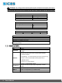
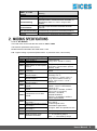
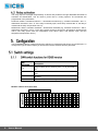
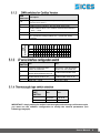
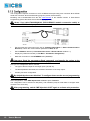
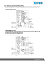
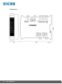
Filename: EAAM035205EN.docx Rev. 05 Date: 28/05/2013 ID Document: EAAM0352 Product: DITHERM ii 1. General Information................................................................................................. 3 1.1 VERSIONS AVAILABLE ....................................................................................... 3 1.2 TECHNICAL DATA ............................................................................................... 3 1.3 INDICATORS ....................................................................................................... 4 2. MODBUS SPECIFICATIONS .................................................................................... 5 3. CanBus specifications ............................................................................................ 6 3.1 EX-BUS ................................................................................................................ 7 3.2 J1939 .................................................................................................................... 7 4. Auxiliary Functions ................................................................................................. 7 4.1 Delta T .................................................................................................................. 7 4.2 Relay activation .................................................................................................... 8 5. Configuration ........................................................................................................... 8 5.1 Switch settings ...................................................................................................... 8 5.1.1 SWN switch functions for RS485 version ....................................................... 8 5.1.2 SWN switches for CanBus Version ................................................................ 9 5.1.3 JP serial interface configuration switch .......................................................... 9 5.1.4 Thermocouple type switch selection ............................................................... 9 5.1.5 Configuration ................................................................................................ 10 5.2 INSTALLATION INSTRUCTIONS ...................................................................... 11 User’s Manual The device lets you connect three independent thermocouples, galvanically isolated from each other and the power source, so the metal side of the thermocouples can make contact with metal surfaces that have a potential other than zero. You can use different types of thermocouples on the same module. It is available in two versions, with CANBUS or RS485 MODBUS communication. A further RS232 connection via Jack is available to configure the device. You can set thresholds for alarms/warnings and the activation of relays, with the relevant response times for each temperature input. DITHERM CANBUS (isolated CAN BUS + non-isolated RS232 with jack connector). E6102094000 xx E6102094001 xx Designed to be used with devices DST4601/PX, GC3xx, GC5xx with CANBUS connection; up to 16 modules with proprietary protocol SICES EX-BUS can be connected, or one module and two thermocouples for reading exhaust gas on left and right banks with J1939 protocol. DITHERM MODBUS RS485 (Isolated RS485 + non-isolated RS232 with jack connector used only for configuration). For use with devices using MODBUS RTU protocol with RS485 connection. Thermocouple Inputs Max. Reading Type Min. temp. temp. resolution 50 °C 1800 B 0.5 °C (note 1) °C 1400 R 0 °C 0.5 °C °C 1530 S 0 °C 0.5 °C °C Thermocouples: J 0 °C 970 °C 0.5 °C E 0 °C 750 °C 0.5 °C 1300 N 0 °C 0.5 °C °C 1300 K 0 °C 0.5 °C °C T 0 °C 350 °C 0.5 °C Number of channels: 3 galvanically isolated Cold junction from 0°C to 60°C compensation: Input impedance: 470 KΩ Sampling time: 300 ms Scale end error 1.5 ‰ 1‰ 1‰ 1‰ 1‰ 1‰ 1‰ 1‰ NOTE 1: with type B thermocouples, due to their characteristics, with temperatures below 50°C, the reading will be 0°C in any case. IMPORTANT: a double selection is required to set the type of thermocouple: the first by changing the software parameters, the second using switches SWA, SWB and SWC. User’s Manual 3 WARNING: the voltage at the measurement inputs of the thermocouples must never be over 10VDC. Otherwise the device will be damaged and the corresponding reading will be wrong. Be careful not to connect the DC power supply instead of a thermocouple. Power input Input voltage Current absorbed Consumption Thermocouple input isolation 7÷32VDC 200 mA (@ 13V) Max. 2.4 W 1000 V Environmental conditions Operating temperature: from -20°C to +60°C from 30 to 90% condensatefree from -20°C to +70°C IP 20 Humidity: Storage temperature: Degree of protection Dimensions/Weight Dimensions: 101Hx35Lx119D Weight: 165 g Connections J1 VDC power supply J4, J6, J7 thermocouple inputs JP 3.5 mm jack RS232 for parameter configuration. J2 RS485 or CANBUS connection. J5 cumulative alarms/prealarms/activations output (NO dry contact relay max. 30VDC @ 500mA) LED Meaning ON WORK Device is powered; flashes to indicate device is functioning correctly Indicates the state of the main communication interface. For can bus version: LED flashing = no communication (bus off or passive error), REMOTE LED on = Can communication active (Active error). For RS485 version: LED off = no communication, LED on = communication active. 4 ALARM OUT Indicates the state of relay output J5 (led ON = contact closed) TEMP 1 Signals on temperature 1 (see table below) TEMP 2 Signals on temperature 2 (see table below) TEMP 3 Signals on temperature 3 (see table below) User’s Manual TEMP1, 2, 3 LED flashing Meaning Off No signal one fast flashing Indicates Delta T function has been activated, so temperature value T3 = T2-T1. Only on LED TEMP3. two fast flashes The relay output activation threshold has been reached. 50% alternate blinking Exceeded high-temperature threshold (Prealarm). Lit fixed Exceeded max. temperature threshold (Alarm). Protocol: Rtu Modbus Two baud rates can be selected with switches: 9600 / 19200 Transmission parameters: N, 8, 1 fixed Modbus address selectable with SWN switch: 1-32 N.B.: register writing is protected (SWN-8=OFF protection active, cannot write). Modbus Registers - Input Register 30001 Conv. points 1 30002 Conv. points 2 30003 Conv. points 3 30015 SWN switch on start-up and current 30019 Test Flag 30031 30032 30033 30061 30062 30063 30101 30102 30103 30105 30106 Temperature of thermocouple 1 Temperature of thermocouple 2 Temperature of thermocouple 3 Temperature 1 in Ex-Bus format Temperature 2 in Ex-Bus format Temperature 3 in Ex-Bus format Alarms and prealarms active for Temp.1 Alarms and prealarms active for Temp.2 Alarms and prealarms active for Temp.3 Relay State Relay activation (from activation threshold) Format 16 bit with sign (range from -32768 to +32767) 8 high bits = power on start-up, 8 low bits = current switch position. 0=OFF, 1=ON 0 = normal operation, 1 = testing board Offset = 0 (only positive values). Accuracy 0.5 ° C Temperature = register value / 2. (e.g.: 945 945/2 = 472.5°C) Temp. value Invalid = 17776 = 8888.0 °C Ex-Bus format (16 bit): Offset = -273°C, 5 decimal bits (divide by 32) Valid values = 0x0000 - 0xFAFE (from -273 to 1734.94°C) 0xFFAFF = Overflow, 0x0000=Underflow 0xFF00 = unavailable, 0xFE01 = sensor disconnected 0=no signal 1=Alarm signal active 2=Prealarm signal active 3=signal. Alarm and prealarm active 0 = contact open, 1 = contact closed Bit 0 = 1 activated by temp.1, bit 1 = 1 activated by temp.2 Bit 2 = 1 activated by temp.3 User’s Manual 5 30201 Presence of CANBUS interface 30202 CANBUS state 40001 40002 40003 Thermocouple type - conv. 1 Thermocouple type - conv. 2 Thermocouple type - conv. 3 High temperature threshold from temp. 1 (Prealarm) Maximum temperature threshold from temp. 1 (Alarm) High temperature threshold from temp. 2 (Prealarm) Maximum temperature threshold from temp. 2 (Alarm) High temperature threshold from temp. 3 (Prealarm) Maximum temperature threshold from temp. 3 (Alarm) Enabling and time for temp.1 prealarm Enabling and time for temp.2 prealarm Enabling and time for temp.3 prealarm Enabling and time for temp.1 alarm Enabling and time for temp.2 alarm Enabling and time for temp.3 alarm 40101 40102 40103 40104 40105 40106 40111 40112 40113 40114 40115 40116 40121 40201 40202 40203 40206 40207 40208 40221 Relay enabling Relay activation threshold from temp.1 Relay activation threshold from temp. 2 Relay activation threshold from temp. 3 Relay deactivation threshold from temp.1 Relay deactivation threshold from temp.2 Relay deactivation threshold from temp.3 Delta T function activation (Temp3 = Temp2 - Temp1) Supported protocols: EX-BUS, J1939 Connection via standard J1939 or PMC bus owner Not compatible with protocol-MTU MDEC 6 User’s Manual 1 = interface present, 0 = not present 0 = Error Active, 1 = Error Passive, 2 = BusOff 0 = none, 1=B, 2=R, 3=S, 4=J, 5=E, 6=N, 7=K, 8=T Thresholds format: threshold value = register value / 2. Accuracy = 0.5 °C Offset = 0 0 = threshold disabled, > 0 = threshold enabled with response time shown in tenths of a second. (25 = 2.5 sec.) 0 = disabled, 1 = enabled on alarms, 2 = enabled on prealarms , 3 = enabled on alarms and prealarms. Thresholds format: threshold = (register value -700/10). Accuracy = 0.1 °C Offset = -70 °C 0 = Off, 1 = On CAN speed: 250 kbit/s CAN settings: sample point at 75%, 11bit identifier (standard format) Messages transmitted EX-BUS: ID MIX L. data Description 0x410 – 0x41F MXDDITEMP 8 byte Temperatures: 2 bytes for each measurement. Format: offset -273 °C, resolution 0.03125 °C/bit. 0x410 – 0x41F MXSDITEMP 6 byte Diagnostics. Contains: board type, firmware revision, CAN error counters, alarm states. Note: each module transmits with a single ID. The ID selection is made with SWN switches 1-4 (EX-BUS ADDRESS). For further information on EX-BUS protocol, refer to EAAS0346xxxx specifications. CAN speed: 250 kbit/s CAN settings: sample point at 75%, 29-bit identifier (extended format) Messages sent to J1939: PGN65031 – Exhaust Temperature (ET): SPN 2433 - Exhaust gas temperature in right exhaust (Temperature 1) SPN 2434 - Exhaust gas temperature in left exhaust (Temperature 2) PGN60461 – DM1 Multipacket Contains PGN60160 (with signals of alarms for spn 2433 and spn 2434) n.b.: J1939 temperature 3 input is not used. Implies only the use of thermocouples T1 and T2 (T3 is not connected); calculates the difference between temperatures T1 and T2 and uses the result in place of temperature T3 (therefore T3 = T2-T1). TEMP3 Led flashes rapidly to indicate the function is activated and the temperature is estimated. The result of the difference is taken as a normal temperature, so it is transmitted instead of T3 and can be associated with thresholds. If T1 or T2 are invalid, T3 will also be invalid. This function is activated by parameter. If the sensor connected to J3 is activated, it won't be detected. User’s Manual 7 The relay output is managed independently of alarms and prealarms through dedicated thresholds of activation and deactivation. Can be used to power fans or cooling systems. The thresholds are programmed in the parameters. POSITIVE LOGIC: activation threshold > = deactivation threshold (e.g., activation threshold = 280 ° C, deactivation threshold = 240 ° C the relay is normally open; when temp. reaches 280 °C, the relay is closed until the temp. drops below 240 °C). NEGATIVE LOGIC: activation threshold < deactivation threshold (e.g. activation threshold = 350°C, deactivation threshold = 370°C the relay remains closed as long as the temperature remains below 370°C. The relay opens when the temperature rises above 370°C and remains open until the temperature drops below 350°C) The DITHERM module is configured using the switches or parameters that can be set via serial port. To configure the type of thermocouple you should use both the switches and the parameter. SWN SWITCHES Description 1- 5 Assign modbus device address (from 1 to 32) with SW6 = ON 6 Modbus address block: ON = from switches 1-5, OFF=1 fixed 7 Not used 8 ON = enable parameter writing Modbus address allocation table 5 4 3 2 1 8 User’s Manual 1 2 3 4 5 6 7 8 9 10 11 12 13 14 15 16 17 18 19 20 21 22 23 24 25 26 27 28 29 30 31 32 SWN DIPSWITCHES ON MODBUS ADDRESS x x x x x x x x x x x x x x x x x x x x x x x x x x x x x x x x x x x x x x x x x x x x x x x x x x x x x x x X x x x x x x x X x x x x x x x X x x x x x x x X SWN Description SWITCHES 5 CanBus protocol selection: OFF=EX-BUS, ON=J1939 6 Modbus address block: ON = address selected with switches 14, OFF = 1 fixed 7 Not used 8 ON = parameter writing enabled, OFF = parameter writing protected 1 2 3 4 5 6 7 8 9 10 11 12 13 14 15 16 ON Assign modbus device address (from 1 to 16) and EX-BUS ID (from 0x410 to 0x41F) SWN DIPSWITCHES 1- 4 4 3 2 1 x x x x x x x x x x x x x x x x x x x x x x x x x x x x x x x x SWP SWITCH ON OFF 1 Insert the 120Ω termination resistor in RS485 line Remove the 120Ω termination resistor from the RS485 line 2 Disable RS232/RS485 serial JP Enable RS232/RS485 serial JP 3 Enable RS232 serial on JP Enable RS485 serial on JP 4 Baud rate = 19200 Baud rate = 9600 SWA, SWB, SWC SWITCH ON OFF 1 B, S, R, T J, E, K, N 2 Not used Not used IMPORTANT: simply setting the switch is not enough to select the type of thermocouple, you must use the software configuration to modify the internal parameters (see following paragraph). User’s Manual 9 The configuration requires connection to a PC via RS232 serial port using Jack connector JP or RS485 serial with connector J2 and the BoardPrg program (version 2.25 and later). BoardPrg can be downloaded from the site www.sices.biz in the software section Sices Board Programming (select the latest version BoardPrg_x_yy_z.msi). Notes: Use cable E090000000142 (RS232-E20931 module connection cable) to connect via a RS232 serial port (JP Jack connector). Set the serial port to be used on the PC (in Communication Menu Select Communication Resource). Check the communication parameters: 9600, N, 8, 1 Set the Modbus address (in Communication menu Serial address: default = 1) Display the parameter window (in File Menu Parameter management) Make the connection to the DITHERM board (Connect). Important: Read the parameters (Read command), and transfer the values to the New Value column, where you can edit them (Copy command). Now you can configure the device, and set: The type of thermocouple for the single inputs (J4, J6, J7). The alarm/prealarm thresholds, the method of activation of the relay output. Auxiliary functions configuration. By default the alarms are disabled. To configure them use the second programming window in BoardPrg. After configuration, check SWE dipswitch 8 is ON and press Transmit. The configuration can be saved on a PC (Save), and reloaded (Load) at a later date to configure other modules in the same way. After programming, switch SWE dipswitch 8 OFF again to activate write protection. 10 User’s Manual The device is designed to be mounted on a DIN 46277 guide in an upright position. It requires adequate ventilation to function properly. If possible, avoid installing above and/or near devices that produce heat. Connections (RS485 version): RS485/CANBUS terminations: To minimize reflections, the first and last device in the BUS 485 network must have an 120 ohm ½ W termination resistor connected in parallel with the line. The same principle applies to the CANBUS network. Connections (CAN BUS version): User’s Manual 11 Dimensions: 12 User’s Manual This document is owned by SICES s.r.l.. All rights reserved. SICES s.r.l. reserves the right to modify this document without prior notice. SICES has made any effort to ensure that the information herein provide are correct; in any case SICES does not assume any liability for the use these information. The disclosure by any means of this document to third parties is not allowed. SSSTTTTTGHTY 1