1
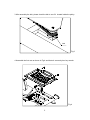
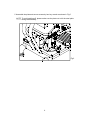
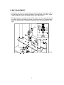
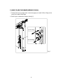
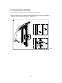
A951
OWNER'S MANUAL
ASSEMBLY INSTRUCTIONS
A. SAFETY INSTRUCTIONS
˙ Read all cautions/warnings and obtain proper instruction on use of the machines
prior to using. Use appropriate positioning and controlled movements.
˙ Assemble and operate the strength on a solid, level surface. Do not use outdoors
or near water.
˙ Never allow children on or near the strength.
˙ Make sure all fasteners are properly tightened for safety. DO NOT use the
strength if the unit is disassembled in any way.
˙ Keep head, limbs, and fingers clear of all moving parts.
˙ If at any time during exercise you feel faint, dizzy or experience pain, stop and
consult you physician.
˙ DO NOT wear loose or dangling clothing while using the equipment. Keep away
from all moving parts.
˙ Use care when mounting and dismounting the unit.
˙ DO NOT use any accessories that aren't specifically recommended by the
manufacturer. These might cause injuries or cause the unit to fall.
˙ Close supervision is necessary when this strength is used by, on, or near
adolescent, invalids, and disabled persons.
˙ Use this strength only for its intended use as described in this manual.
˙ Never operate this strength if it has been damaged in any way. If it is not working
properly, been dropped or damaged, contact your dealer. DO NOT attempt to fix a
broken or jammed machine. Notify floor staff.
˙ Never drop or insert any object into any opening.
1
B. Introduction
Badge, rear
Badge, front
Side frame
Front cover(B)
Usage sticker
Rear cover
Front cover(A)
Selection pin (3.5 Lbs / 1.5 kgs)
Selection pin (6.5 Lbs / 3 kgs)
Cord
Stack fork
Left pad
Seat back
Weight stacks (11 Lbs / 5 kgs)
Main frame
Seat
Right pad
Foot mat
Multi-conjoint
bar
Ring
-shapped
plate B
Ring-shapped plate A
Ring-shapped plate C
Foot plate
Setting control bar
2
C. List of Parts
1. One double-end open wrench, 8mm x 10mm
2. One double-end open wrench, 8mm x 17mm
3. One double-end open wrench, 12mm x 15mm
4. One double-end open wrench, 17mm x 23mm
5. One hex key wrench, M4
6. One hex key wrench, M5
7. One hex key wrench, M6
8. User's manual
9. One storage tray
3
D. STEP BY STEP INSTRUCTION:
1. Hold the side frame during assembly, then connect the frame to the side frame.
Secure screws tightly as shown in Fig.1.
Fig.1
2. Screw up the belt with open wrench (10 mm & 12 mm) as shown in Fig.2.
Fig.2
4
3. After assembly the belt, please check the belt to see if it located inside the pulley.
Belt
Fig.3
4. Assemble the foot mat as shown in Fig.4 and faster 4 screws by hex key wrench.
Fig.4
5
5. Assemble the plate and secure screws by hex key wrench as shown in Fig.5.
NOTE: To avoid painting off, please make sure the plate not to hit the steel plate
during the assembly.
Fig.5
6
E. BELT ADJUSTMENT:
1. If the belt is too tight or too loose, first loosen nut A as shown then adjust nut B. If
the belt length is too long, adjust downward; if the belt length is too short, adjust
upward. Adjust the belt to the proper position, then tighten nut A.
2. The gap between nut A and B must be within 35mm(1.4"). If the gap still exceeds
the 35mm limit after the first step, please loosen the screws on C and adjust the
belt to the proper length. Tighten the screws and follow the 1st step again. (See
fig.6)
Fig.6
7
F. HOW TO USE THE MINOR WEIGHT STACK:
1. To adjust the minor weight stack, insert the upper pin to add 3.5Lbs/1.5kgs or the
lower pin to add 6.5Lbs/3kgs.
2. Pull the pin to release the weight. (See fig.7)
(3.5Lbs/1.5Kgs)
(6.5Lbs/3Kgs)
Fig.7
8
G. STORAGE TRAY ASSEMBLY:
1. Remove the existing screws and washers from tubing.
2. Place storage tray onto tubing and tighten with the screws and washers
that you just removed from step 1. (See Fig. 8)
Fig.8
9
Usage Instruction:
10