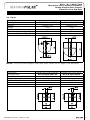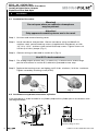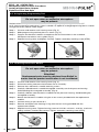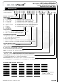
1
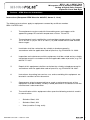
Technical Description / User’s Guide
BTL5-_-M_-J-DEXC-TA12
Micropulse Linear Position Transducer
Analog & Digital-Pulse Outputs
Explosion-Proof (Flame-Proof) Rod Style
BTL5-_-M_-J-DEXC-TA12
Micropulse Linear Position Transducer
Analog & Digital-Pulse Outputs
Explosion-Proof Rod Style
Contents
i
Preface - ATEX Directive Instructions......................................... 3-4
1Introduction....................................................................................... 4
1.1 Scope.................................................................................................. 4
1.2 Safety Advisory................................................................................... 4
1.3Approvals............................................................................................ 5
2
General Information.......................................................................... 5
2.1 Functional Description........................................................................ 5
3
Component Overview................................................................... 6-7
4
Mechanical Data............................................................................... 8
4.1Dimensions......................................................................................... 8
4.2 Specifications..................................................................................... 9
5Accessories..................................................................................... 10
5.1Magnets............................................................................................ 10
5.2 Conduit Adapter............................................................................... 10
5.3 Floats................................................................................................ 11
6
Installation Instructions.................................................................. 12
6.1 Installation Procedure (mounting bolt
specifications, tightening torque, etc.).............................................. 12
6.2 Installation in Hydraulic/Pneumatic Cylinders ................................. 12
6.3 Installing in Zone 0 Locations........................................................... 13
6.4Wiring................................................................................................ 13
6.5 Using Analog Programming Tool...................................................... 14
6.6 Replacing Electronics Module ......................................................... 14
7
Ordering Code................................................................................. 15
The CE Mark verifies
that our products meet
the requirements of
EC Directive
2004/108/EC (EMC Directive)
and the EMC Law. Testing in our EMC
Laboratory, which is accredited by
DATech for Testing Electromagnetic
Compatibility, has confirmed that
Balluff products meet the EMC
requirements of the following Generic
Standards:
• EN 61000-6-4 (emission)
• EN 61000-6-2 (noise immunity)
2
Emission tests:
RF Emission
EN 55011 Group 1, Class A
Noise immunity tests:
Static electricity (ESD)
EN 61000-4-2 Severity level 3
Electromagnetic fields (RFI)
EN 61000-4-3 Severity level 3
Fast transients (Burst)
EN 61000-4-4 Severity level 3
Surge
EN 61000-4-5 Severity level 2
Line-induced noise induced by
high-frequency fields
EN 61000-4-6 Severity level 3
Magnetic fields
EN 61000-4-8 Severity level 4
1-800-543-8390 • WWW.BALLUFF.COM
BTL5-_-M_-J-DEXC-TA12
Micropulse Linear Position Transducer
Analog & Digital-Pulse Outputs
Explosion-Proof Rod Style
i
Preface - ATEX Directive Instructions
Instructions (European ATEX Directive 94/9/EC, Annex II, 1.0.6.)
The following instructions apply to equipment covered by certificate number
SIRA 11ATEX1104X:
1.
The equipment may be used with flammable gases and vapours with
apparatus groups IIC and with temperature classes T6 and T5.
2.
The equipment is only certified for use in ambient temperatures in the range
-20°C to +65°C (T6) or -20°C to +80°C (T5) and should not be used outside
these ranges.
3.
Installation shall be carried out by suitably trained personnel in
accordance with the applicable code of practice, e.g. EN 60079-14: 2003.
4.
Inspection and maintenance of this equipment shall be carried out by suitably
trained personnel in accordance with the applicable code of practice, e.g. EN
60079-17: 2007.
5.
Repair of this equipment shall be carried out by suitably trained personnel in
accordance with the applicable code of practice, e.g. EN 60079-19: 2007.
6.
Instructions for putting into service, use, and assembling this equipment are
located in section 6 of this document.
7.
Components to be incorporated into or used as replacement parts of the
equipment shall be fitted by suitably trained personnel in accordance with the
manufacturer’s documentation.
8.
The certification of this equipment relies upon the following materials used in
its construction:
–
Stainless Steel, 316
–
Stainless Steel, 304
–
Viton (used for O-ring seals)
WWW.BALLUFF.COM • 1-800-543-8390
3
BTL5-_-M_-J-DEXC-TA12
Micropulse Linear Position Transducer
Analog & Digital-Pulse Outputs
Explosion-Proof Rod Style
i
Preface - ATEX Directive Instructions (cont.)
If the equipment is likely to come into contact with aggressive
substances, then it is the responsibility of the user to take suitable
precautions that prevent it from being adversely affected, thus
ensuring that the type of protection provided by the equipment is not
compromised.
1
Aggressive Substances:
e.g. acidic liquids or gases that may
attack metals, or solvents that may affect
polymeric materials.
Suitable Precautions:
e.g. regular checks as part of routine
inspections or establishing from the material’s
data sheets that it is resistant to specific
chemicals.
9.
See the diagram of the product label in section 3 of this document for
appropriate markings, ratings, and manufacture contact information.
10.
The characteristics of the equipment are detailed in section 4 of this
document.
Introduction
Read this manual before installing and operating the Micropulse Transducer.
1.1 Scope
This document provides installation instructions and technical data specific to the
Micropulse EX transducer. Detailed technical specifications for the electronics package
can be found in the standard Micropulse transducer User’s Guides, corresponding to the
relevant type of output signal.
1.2 Safety Advisory
Read this manual before installing the Micropulse EX transducer. The Micropulse EX
transducer should be installed by qualified personnel and used in accordance with the
conditions for which it was designed. Any unauthorized modification could result in
equipment damage or personal injury, and is expressly forbidden.
4
1-800-543-8390 • WWW.BALLUFF.COM
BTL5-_-M_-J-DEXC-TA12
Micropulse Linear Position Transducer
Analog & Digital-Pulse Outputs
Explosion-Proof Rod Style
1.3 Use and inspection
The relevant safety regulations must be followed when using the transducer system.
In particular, steps must be taken to ensure that should the transducer system
become defective, no hazards to persons or property can result. This includes the
installation of additional safety limit switches, emergency shutoff switches and
maintaining the permissible ambient conditions.
Approvals:
11-2411253X
Class I, Division 1, Groups A, B, C, and D
Class II, Division 1, Groups E, F, and G; Class III
T6 Ta=65°C, T5 Ta=80°C Type 4X/6P; IP68
Class I, Zone 1 AEx d IIC T6 Ta=65°C, T5 Ta=80°C
Class I, Zone 1 Ex d IIC T6 Ta=65°C, T5 Ta=80°C
SIRA 11ATEX1104X
IECEx SIR 11.0048X
II 1/2GD
Ex d IIC T6/T5 Ga/Gb Ta +65°C (T6) +80°C (T5)
Ex t IIIC T85/T100°C Da IP68 Ta +65°C (T85) +80°C (T100)
0518
2
General Information
2.1 Functional Description
The Micropulse EX Linear Position Transducer is designed to provide highly accurate linear
position feedback in areas containing potentially explosive gases and dusts.
The Micropulse EX Linear Position Transducer consists of:
• A heavy-duty stainless steel housing with a ½”-14 NPT threaded conduit opening for
cable entry.
• An internal electronics module/sensing element that provides electrical position
feedback signals in the form of an analog voltage, analog current, or digital pulse
signals. The internal electronics module/sensing element can be replaced while the
external housing stays in place.
WWW.BALLUFF.COM • 1-800-543-8390
5
BTL5-_-M_-J-DEXC-TA12
Micropulse Linear Position Transducer
Analog & Digital-Pulse Outputs
Explosion-Proof Rod Style
3
Component Overview
9
13
11
3
10
12
15
Key:
1. Housing Cover.
4
2. Electronics Module.
14
3. Pressure Housing.
4. Conduit Entry (1/2”-14 NPT).
5. Analog Programming Tool (optional). See section 6.5 for additional information.
6. Wiring Terminal Block. See section 6.4 for wiring information.
7. Electronics Module Retaining Screws.
8. Housing Screws. M6x45 A2 Socket-Head Cap Screws (6x–included).
(Replacement Screw Kit: BTL5-A-FK01-E-J-DEX)
9. Float Magnet–For use in liquid-level applications. See section 5.3 for additional options.
10. Position Magnet. See section 5.1 for additional magnet sizes.
11. Housing Cover O-Ring.
12. Flange O-Ring (not visible).
13. External Housing GND.
14. Internal Housing GND.
15. 1/2”-14 NPT-to-M20 Adapter (optional). See section 5.2 for additional information.
16. Product Label (enlarged to show content).
17. Ordering code for complete transducer assembly.
18. Cover secondary retaining screw.
19. Location of ordering code for replacement electronics module.
6
1-800-543-8390 • WWW.BALLUFF.COM
BTL5-_-M_-J-DEXC-TA12
Micropulse Linear Position Transducer
Analog & Digital-Pulse Outputs
Explosion-Proof Rod Style
17
BTL5-xxx-Mxxxx-J-DEXC-TA12
18
16
8
2
7
19
5
6
1
WWW.BALLUFF.COM • 1-800-543-8390
7
Electrical Interface
Analog, Digital, SSI, Quadrature
Profibus, CANbus
Dim. A (mm)
104.12 135.62
8
Dim. C (mm)
59.5
91
4
Dim. B (mm)
96.12
127.62
Mounting is accomplished
using six M6x45 A2 (stainless)
socket-head cap screws
(supplied with transducer) or six
1/4"-20x1-3/4" socket-head
cap screws (user-supplied)
BTL5-_-M_-J-DEXC-TA12
Micropulse Linear Position Transducer
Analog & Digital-Pulse Outputs
Explosion-Proof Rod Style
Mechanical Data
4.1 Dimensions
1-800-543-8390 • WWW.BALLUFF.COM
WWW.BALLUFF.COM • 1-800-543-8390
Housing/Rod Material
Cover Material
Cover O-Ring Material
Pressure Rating, Rod
Operating Temperature
Storage Temperature
Humidity
Electrical Performance Specifications
Take care to prevent the possibility of condensation
in the conduit from entering the transducer housing.
Stainless steel, 316
Stainless steel, 304
Viton
8700 psi
-40°C to +80°C (-40°F to +176°F)
-20°C to +80°C (ATEX Applications)
-40°C to +85°C (-40°F to +185°F)
<90%, non-condensing
For complete electrical and performance specifications, refer to Micropulse B/Z-housing User Guides for the appropriate output type
*To maintain the IP68 rating, ensure that the connection at the conduit opening also meets this standard.
Thread sealant should be used to ensure
protection against moisture ingress.
Linear Displacement
51 mm (2 in.) to 5080 mm (200 in.)
Internal screw-type terminal block
100 g/6 ms per IEC 68-2-27
12 g, 10 to 200 Hz per IEC 68-2-6
IP68*
Specifications
Measurement Type
Measuring Range
Connection Means
Shock Rating
Vibration Rating
Environmental Protection
BTL5-_-M_-J-DEXC-TA12
Micropulse Linear Position Transducer
Analog & Digital-Pulse Outputs
Explosion-Proof Rod Style
4.2 Specifications
9
BTL5-_-M_-J-DEXC-TA12
Micropulse Linear Position Transducer
Analog & Digital-Pulse Outputs
Explosion-Proof Rod Style
5
Accessories (Order Separately)
5.1 Magnets
Description
Ordering Code
Ring Magnet
BTL-P-1013-4R
Material
Weight
Slotted Magnet
BTL-P-1013-4R
AL
12 g
Small Ring Magnet
BTL-P-1012-4R
AL
12 g
AL
12 g
26.80
5.2 Conduit Adapter
Description
Part Number
Material 1/2" – 14 NPT to M20 Adapter
BTL-A-AD09-M-00EX
Nickel-Plated
Dia.15 Brass
21.85
½” NPT Threads
43
20
26.80
Dia.15
Top View
18
21.85
½” NPT Threads
M20 Threads
20
18.40
AEx de Class 1, Zone 1, Groups I & IIC
Class I Division 1 & 2, Groups A, B, C, D
Class II & III, Groups E, F, G
43
SIRA00ATEX1094
EEx de I & IIC
I M2, II 2 GD
18
Approvals
10
1-800-543-8390 • WWW.BALLUFF.COM
BTL5-_-M_-J-DEXC-TA12
Micropulse Linear Position Transducer
Analog & Digital-Pulse Outputs
Explosion-Proof Rod Style
5.3 Floats
Description
Ordering Code
Material
Weight
Minimum Fluid Density
Immersion Depth in 1 g/cm3(H20)
Immersion Depth in 0.7 g/cm3
Spherical Float
BTL2-S-5113-4K-EX
Stainless 316
26 g
0.7 g/cm3
26 mm
40 mm
Bullet Float
BTL2-6216-8P-EX
Stainless 316
41 g
0.6 g/cm3
41 mm
57 mm
NOTE: The use of float magnets other than those shown on this page is not approved.
Description
Ordering Code
Material
Weight
Minimum Fluid Density
Immersion Depth in 1 g/cm3(H20)
Immersion Depth in 0.7 g/cm3
WWW.BALLUFF.COM • 1-800-543-8390
Barrel Float, Liquid Interface
BTL2-S-4414-4Z01-EX
Stainless 316
52 g
0.85 g/cm3
45 mm
Sinks
Barrel Float, Liquid Level
BTL2-S-4414-4Z-EX
Stainless 316
34 g
0.7 g/cm3
30 mm
39 mm
11
BTL5-_-M_-J-DEXC-TA12
Micropulse Linear Position Transducer
Analog & Digital-Pulse Outputs
Explosion-Proof Rod Style
6
Installation
6.1 Installation Procedure
Warning!
Do not open when an explosive atmosphere
may be present.
Attention!
Only approved conduit systems are to be used.
Step 1: Unscrew and remove housing cover.
Step 2: Install transducer into position. Secure transducer using six M6x45 A2,
stainless steel, socket head cap screws (supplied with transducer), or with
1/4”-20 x 1-3/4”, stainless steel socket head cap screws. Tighten screws to
3.5 Nm (2.6 ft-lbs.) torque. (Fig. 1)
Step 3: Connect wiring as indicated in section 6.4. (Fig. 2)
Use 90°C rated conductors.
Step 4: For analog output versions only—If necessary, scale the active stroke range
per the instructions in section 6.5; otherwise, proceed to next step.
Step 5: Replace the housing cover and tighten to 25 ft-lbs. minimum, 30 ft-lbs. maximum. Tighten secondary retaining screw (ATEX).
Fig. 1
Fig. 2
6.2 Installation in Hydraulic/Pneumatic Cylinders
If the transducer is to be installed in a cylinder, prepare the cylinder port in accordance with
the diagram below.
thru-hole
Bevel for O-Ring 15.4x2.1
12
1-800-543-8390 • WWW.BALLUFF.COM
BTL5-_-M_-J-DEXC-TA12
Micropulse Linear Position Transducer
Analog & Digital-Pulse Outputs
Explosion-Proof Rod Style
6.3 Installing in Locations Classified as Zone 0 Under ATEX and IECEx Guidelines
Only the rod section of the transducer may extend into Zone 0. To ensure
safe isolation between Zone 0 and Zone 1, the relevant safety regulations
detailed in IEC/EN60079-26 must be strictly adhered to. The transducer must
be installed in a manner that will result in a sufficiently tight joint (IP67) or
flameproof joint (IEC/EN60079-1) between the less hazardous area
and Zone 0.
Zone 1
When using a float magnet, it is necessary that a static discharge
between the transducer rod and the inner portion of the float
Dividing Area
be prevented. The floats listed in the accessory section (5.2) are
Zone 0
designed so that, in normal operation, the float is tilted, thereby
ensuring mechanical contact between the transducer rod and the float wall.
Do not use other types of floats or attempt to disable this design feature.
Note: The transducer is not approved for use in location classified as Zone 0
under North American guidelines.
6.4 Wiring
Output Type (Ordering Code)
Fig. 1
Analog Voltage
(A/B/G)
Analog Current
(C/E)
Digital START/
STOP (I/K/M/N/P)
Digital PWM (L/R)
SSI
(S)
1
not used
Signal Out
Interrogate (+)
(input)
Interrogate (+)
(input)
CLK (+)
(input)
2
signal GND
Signal GND
START/STOP (+)
(output)
GATE (+)
(output)
DATA (+)
(output)
3
Signal Out (failing)
not used
Interrogate (-)
(input)
Interrogate (-)
(input)
CLK (-)
(input)
Pin
1
4
Pwr Supply GND
Pwr Supply GND
Pwr Supply GND
Pwr Supply GND
Pwr Supply GND
5
Pwr Supply
(+10 to +30 vdc)
Pwr Supply
(+10 to +30 vdc)
Pwr Supply
(+10 to +30 vdc)
Pwr Supply
(+10 to +30 vdc)
Pwr Supply
6
Signal Out (rising)
not used
START/STOP (-)1
(output)
GATE (-)
(output)
DATA (-)
(output)
7
not used
not used
not used
not used
not used
Note 1: Ordering code version "N" is a single-ended, TTL compatible START/STOP version. This version does not use
Interrogate (-) or START/STOP (-). Pins 3 and 6 should be left unconnected for "N" type transducers.
Output Type (Ordering Code) Fig. 2
Pin
Profibus (T)
1
RxD/TxD-N
2
RxD/TxD-P
3
Data GND
4
Pwr Supply GND
10 9
5
Pwr Supply (+)
6
VP (+5V Output)
7
Not used
8
Not used
Pin
1
2
3
4
5
6
7
8
9
10
8
10
7
9
8
68 57 46 35
10
6
427 13
52 41
3
2
1
8
7
68 57 46 8
35
7
2
4
613 52 4 1 3
9
2
8
1
10
Fig. 1
Fig. 2
9
10
68 57 46 835 74
2 613 5 2 4 1 3
7
9
10
2
1
9
Fig. 3
Output Type (Ordering Code) Fig. 3
Quadrature (Q)
CANbus (H)
Output Channel A (+)
CAN GND
Output Channel B (+)
CAN Low
Outpur Channel A (-)
CAN High
Pwr Supply GND
Pwr Supply GND
Pwr Supply (+10 to +30 Vdc)
Pwr Supply (+24V)
Output Channel B (-)
CAN GND
Output Channel Z (+)
CAN Low
Output Channel Z (-)
CAN High
Strobe Input
Not used
Not used
Not used
WWW.BALLUFF.COM • 1-800-543-8390
Typical housing with terminal
block assembly.
13
BTL5-_-M_-J-DEXC-TA12
Micropulse Linear Position Transducer
Analog & Digital-Pulse Outputs
Explosion-Proof Rod Style
6.5 Using Analog Programming Tool
Warning!
Do not open when an explosive atmosphere
may be present.
Versions of the Micropulse EX transducer with an analog output, (ordering code A, B, C, E
or G), have an electrical stroke that is 100% scalable. An optional analog programming tool is used to
change the factory default stroke length.
Step 1: Unscrew and remove main housing cover. (Fig. 5)
Step 2: Slide programming tool into place as shown. (Fig. 3)
Step 3: Program the electrical stroke in accordance with the instructions in the standard
Micropulse transducer user’s guide. (Fig. 4)
Step 4: Replace housing cover and tighten securely. Tighten secondary retaining screw (ATEX).
Fig. 4
Fig. 3
Optional Analog Programming Tool BTL5-A-EH03
6.6 Replacing Electronics Module
Warning!
Do not open when an explosive atmosphere
may be present.
Attention!
Replacement parts must be obtained from Balluff to
ensure that the product certification is not invalidated.
Step 1: Unscrew and remove main housing cover. (Fig. 5)
Step 2: Disconnect wiring and note wire locations for re-assembly.
Step 3: Remove the 2 electronics module retaining screws.
Step 4: Carefully slide electronics module/waveguide assembly out of the pressure housing.
Avoid bending the waveguide assembly. (Fig. 6)
Step 5: Carefully slide the new electronics module into the pressure housing. Avoid bending the
waveguide assembly.
Step 6: Secure the electronics module using the 2 new screws provided with the replacement
module.
Step 7: Connect wiring as per section 6.4.
Step 8: Remove and replace the housing O-ring with the new O-ring provided with the
replacement module.
Step 9: Replace housing cover. Tighten housing cover to 25 ft-lbs. minimum, 30 ft-lbs. maximum.
Mating surfaces should make contact. Tighten secondary retaining screw (ATEX).
Fig. 5
14
Fig. 6
1-800-543-8390 • WWW.BALLUFF.COM
BTL5-_-M_-J-DEXC-TA12
Micropulse Linear Position Transducer
Analog & Digital-Pulse Outputs
Explosion-Proof Rod Style
7
Ordering Code
Replacement Module Only
Complete Transducer
B T L 5 - A 1 1 - M 0 3 0 5 - J - M 0 1
- T A
B T L 5 - A 1 1 - M 0 3 0 5 - J - D E X C - T A 1 2 - E 4
Balluff - Transducer - Linear
Generation 5
Output
A = 0 to 10Vdc
I = Differential start/stop with tri-state
B = -5 to +5Vdc
K = Differential stop - leading edge active
C = 0 to 20 mA
L = Differential pulse-width modulated
E = 4 to 20 mA
M = Differential start/stop - leading edge active
G = -10 to +10 Vdc
N = Single ended start/stop - leading edge active
S = SSI
P = Differential start/stop - trailing edge active
T = Profibus
R = Differential pulse-width - recirculated
H = CANopen
Q = Quadrature
Supply Voltage
1 = +24 Vdc ± 20% (H, T and S output versions only)
5 = +10... + 30 Vdc (all other output types)
Analog Output Operation
Voltage Output (type A, B, or G)
1 = User selectable rising or falling
Current Output (type C & E)
0 = Minimum output at connector end (rising toward opposite end)
7 = Maximum output at connector end (falling towards opposite end)
Nominal Stroke Length
0 3 0 5 = 305 mm active stroke
Housing Type
J = Rod-style, smooth flange, o-ring seal
Protection Method/Rod Termination
DEX = Flameproof, C = Universal end plug
Connection Type
T A 1 2 = Terminal block connection, 1/2"-14 NPT conduit entry
Interrogation (only vaild if output type=R, otherwise leave blank)
I = Internal interrogation, E = External interrogation
Recirculation (only valid if output type = R, otherwise leave blank)
1 = 1 circulation, 2 = 2 circulations, 4 = 4 circulations, 8 = 8 circulations, 16 = 16 circulations
Standard Stroke Lengths, Inches (mm)
2(0051)
3(0076)
3.5(0090)
4(0102)
5(0127)
6(0152)
7(0178)
8(0203)
9(0230)
10(0254)
11(0280)
12(0305)
13(0330)
15(0381)
16(0407)
18(0457)
20(0508)
22(0560)
24(0610)
26(0661)
28(0711)
30(0762)
32(0813)
36(0914)
40(1016)
42(1067)
48(1220)
50(1270)
54(1372)
60(1524)
WWW.BALLUFF.COM • 1-800-543-8390
66(1676)
69(1753)
72(1829)
78(1981)
84(2134)
89(2261)
98(2490)
108(2743)
118(2997)
126(3200)
140(3556)
144(3658)
148(3759)
152(3861)
156(3962*)
160(4064)
164(4166)
168(4267)
172(4369)
176(4470)
180 (4572**)
184(4674)
188(4674)
192(4877)
196(4978)
200(5080)
* Max Length for CANopen,
Profibus, and SSI
** Max Length for Analog
15
Germany
Global Headquarters
Balluff GmbH
Schurwaldstraße 9
73765 Neuhausen a.d.F.
Telefon: +49 (0)71 58/1 73-0
Telefax: +49 (0)71 58/50 10
Hotline: +49 (0)71 58/1 73-370
Web: www.balluff.de
E-mail: [email protected]
USA
North American Headquarters
Balluff Inc.
8125 Holton Drive
Florence, KY 41042
Phone: (859) 727-2200
Toll-free: 1-800-543-8390
Fax: (859) 727-4823
Web: www.balluff.com
E-Mail: [email protected]
Canada
Balluff Canada, Inc.
2840 Argentia Road, Unit #2
Mississauga, Ontario L5N 8G4
Phone: (905) 816-1494
Toll-free: 1-800-927-9654
Fax: (905) 816-1411
Web: www.balluff.ca
E-mail: [email protected]
Mexico
Balluff de Mexico S.A. de C.V
Prol. Av. Luis M. Vega #109
Col. Ampliacion Cimatario
Queretaro, QRO 76030
Phone: (++52 442) 212-4882,
224-3583, 224-3171
Fax: (++52 442) 214-0536
E-mail: [email protected]
Inductive
Sensors
Photoelectric
Sensors
MicropulseTM
Transducers
Capacitive
Sensors
Magnetic Field
Sensors
Electromechanical
Sensors
Identification
Systems
Connectors &
Accessories
No. 883680 E • Edition 2011-04 • Subject to change • Replaces Edition 2009-11
Complete Product Range