1
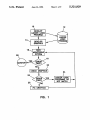
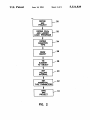
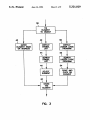
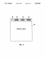
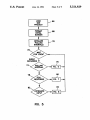
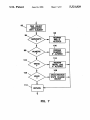
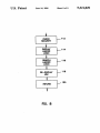
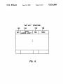
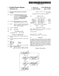
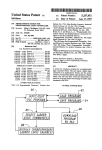
IlllllllllllllIllIlllllllllIlllllllllllllllllllllllllllllIlllllllllllllllll
US005321829A
United States Patent [191
Zifferer
MONITORING LADDER LOGIC
PROGRAMS
[21] Appl. No.: 556,958
Jul. 20, 1990
[51]
[52]
Int. Cl.5 .............................................. .. G06F 9/00
US. Cl. .................................. .. 395/575; 395/159;
[58]
Field of Search ...... .. 395/575, 600, 650, 191-192,
[56]
395/147, 159; 364/147, 188; 371/29.l
References Cited
371/291; 364/147; 364/DIG. 1; 364/2751
U.S. PATENT DOCUMENTS
8/1972
5/ 1974
5/ 1975
6/1976
7/1977
Fletcher et al. .
Struger et al. .
Johnstone .
Wanauchi et a1. .
Dummermuth et al. .
4,200,914
4/ 1980
Kintner .
5,321,829
Jun. 14, 1994
cessor.
[75] Inventor: Scott C. Zifferer, Mequon, Wis.
[73] Assignee: ICOM, Inc., West Allis, Wis.
3,686,639
3,813,649
3,882,305
3,964,026
4,038,533
Patent Number:
Date of Patent:
erations Manual”, Bulletin 1772, Mini PLC-2/05 Pro
[54] GRAPHICAL INTERFACES FOR
[22] Filed:
[11]
[45]
Icom, Inc., “PLC~2 Ladder Logistics User’s Manual”,
Aug. 1987.
Icom, Inc., “PLC-5 Ladder Logistics User's Manual”,
Sep. 1987.
Taylor Industrial Software, “Product Bulletin #24”,
Apr. 1987.
Icom, Inc., “PLC-3 Ladder Logistics User’s Manual”,
Sep. 1987.
Taylor Industrial Software, "Product Summary”, Feb.
1988.
Taylor Industrial Software, “Product Bulletin #21”,
Apr. 1987.
PLC-5 Ladder Logistics User’s Manual, Sep. 1987,
Icom, Inc.
MMI Logistics User’s Manual, May 1990, loom, Inc.
Primary Examiner-Paul V. Kulik
Assistant Examiner-Jennifer M. Orzech
Attorney, Agent, or Firm-Merchant, Gould, Smith,
-
4,227,247 10/1980 Kintner .
4,244,034 l/198l Cherba .
4,247,901 1/1981 Martin et al. .
4,316,260 2/1982 Hideshima ,
4,396,974 8/ 1983 Imazeki et al. .
4,415,965 11/1983 Imazeki .
4,445,169 4/1984 Wakiti et a1. .
4,449,180 5/1984 Ohshima et al. .
Edell, Welter & Schmidt
[57]
ABSTRACT
4,486,830 12/1984 Taylor, Jr. et a1. .
4,488,258 12/1984 Struger et al. .
4,513,379 4/1985 Wilson et al. .
4,533,997 8/1985 Furgerson .
A menu-driven system for developing Man-Machine
Interfaces (MMI) for use in the graphical monitoring of
ladder logic programs executing in programmable logic
controllers PLCs. The Man-Machine Interfaces graphi
cally depict plant processes controlled by the PLC.
Data from the PLC representing plant process events
(flows, state changes, tank levels, etc.) are communi
cated to the Man-Machine Interfaces. A Development
4,635,183
4,644,478
l/1987 Isobe et al. .
2/1987 Stephens et al. .
structing the Man-Machine Interfaces. Ladder logic
4,661,899
4/1987
programs and databases associated therewith are im
Usuda .
4,663,704 5/1987 Jones et a1. .
4,703,414 10/1987 Inoue et al. .
4,718,025 l/ 1988 Minor et al. .
4,815,014
3/1989 Lipner et al. .
4,833,592
4,843,538
4,991,076
5/1989 Yamanaka .
6/1989 Lane et a1. .
2/ 1991 Zift'erer et a1. .................... .. 364/147
5,127,099
6/1992
Zifferer et a1. .................... .. 395/725
System provides a programmer’s “tool box” for con
ported and accessed by the Development System for
use in the development of the Man-Machine Interfaces.
A Runtime System provides an execution environment
for the Man-Machine Interfaces. The Runtime System
has the ability to access ladder logic programs during
monitoring operations. A user can “hot-key” to the
ladder logic program for trouble-shooting purposes.
OTHER PUBLICATIONS
Allen-Bradley Company, Inc., “Programming and Op
12 Claims, 9 Drawing Sheets
US. Patent
June 14,1994
Sheet 1. of 9
10
5,321,829
12
\
LASSE’RFLESGIC
PROGRAM
-
‘
LADDER
DEVELOP
LOGIC
PROGRAM
14
\
GRAPHICS
16\
TEST
MONITORING _
28
SYSTEM
18
ms
20
NO
/
CHECK GRAPHICS
74
LADDER LOGIC
PROGRAMS DO —>
NOT MATCH
\
NO
FIX CRAPHics
FIG. 1
US. Patent
June 14, 1994
Sheet 2 of 9
DEFINE
MMI
PROJECT
I
DEFINE PLCS
AND LADDER
LOGIC PROGRAMS
I
DEFINE
ANIMATION
TYPE
I
DRAW
OBJECT
I
TIE
ELEMENT
TO OBJECT
I
SEI'
POLLING
INTERVAL
I
SET
ANIMATION
'IYPE PARAMETERS
I
SAVE
MMI
PROJECT
FIG. 2
5,321,829
US. Patent
June 14, 1994
'
5,321,829
Sheet 3 of 9
3a
\
TIE
ELEMENT
TO OBJECT
42
5O
\
\
ELEMENT NAME
OR ADDRESS
DISPLAY
SYMBOL
DISPLAY
LADDER LOGIC
UST
PROGRAM
44\ x
SEARCH
SYMBOL
UST
46\ l
SELECT
52\ 1
SEARCH
LADDER LOGIC
PROGRAM
54\ 1
POINT AND
CUCK ON
48\ 1
STORE
—--———-——>
THE
ELEMENT
FIG. 3
_——————‘
US. Patent
June 14, 1994
Sheet 4 of 9
58‘
6O
62
64
/
l
l
l
PLO
ELEMENT
ADDRESS
POLUNG
INTERVAL
ANIMATION
ACTIONS
5,321,829
56
GRAPHICAL OBJECT
FIG. 4
US. Patent
June 14, 1994
LOAD
MMI
PROJECT
FORMAT
INITIAL
SCREEN
INITIALIZE
POLLING
INTERVALS
72
EVENT
OCCURRED
74
78
POLL
RESPONSE
82
FIG. 5
Sheet 5 of 9
5,321,829
US. Patent
June 14, 1994
l
l
l
T
SEND QUERY
Sheet 6 of 9
/86
TO PLC
RESET POLLING
INTERVAL
RETURN
FIG. 6
/86
5,321,829
U.S. Patent
'
June 14, 1994
Sheet 7. of 9
i
92\
FIND OBJECT
ASSOCIATED
WITH ELEMENT
94
/
REDRAW
BAR IF
ALTERED
1 00
]
REDRAW
NUNERIC
-->
\F ALTERED
104
102
a
-
/
REDRAW
TREND LINE
—>
IF ALTERED
10a
/
10s
- DRAW/REDRAW
STATE CHANGE -—>
OBJECT
110
RETURN
_
FIG. 7
US. Patent
June 14, 1994
Sheet 8 of 9
%
CHECK
/ 1 12
SECURITY
i
DISPLAY
LADDER
1
/ 1‘
LOGIC
i
SEARCH
LADDER
/
1'15
LOGIC
RE-DISPLAY
/ “8
um
i
RETURN
FIG. 8
/12o
5,321,829
US. Patent
Sheet 9 of 9
June 14, 1994
I'HOT KEY " STRUCTURE‘
1/22
1 24
1 26
l'GOTO
FIG. 9
1 28
5,321,829
1
5,321,829
2
accessed by the Development System for use in the
development of the Man-Machine Interfaces.
A Runtime System in the preferred embodiment pro
GRAPHICAL INTERFACES FOR MONITORING
LADDER LOGIC PROGRAMS
vides an execution environment for the Man-Machine
5 Interfaces. The Runtime System has the ability to access
BACKGROUND OF THE INVENTION
ladder logic programs during monitoring operations. A
1. Field of the Invention
user can “hot-key” to the ladder logic program for
This invention relates in general to monitoring sys
tems for programmable logic controllers (PLCs), and in
trouble-shooting purposes.
particular, to a system for developing Man-Machine
Interfaces to graphical monitor ladder logic programs
executing in PLCs.
2. Description of Related Art
PLCs perform many of the control functions for
BRIEF DESCRIPTION OF THE DRAWINGS
Referring now to the drawings in which like refer
ence numbers represent like elements throughout the
several views:
assembly line machines, machine tools, and other types
of industrial equipment. For example, a part arriving at
FIG. 1 is a ?owchart illustrating a typical develop
ment and test cycle in the preferred embodiment;
FIG. 2 is ?owchart illustrating the steps performed
by the Development System in constructing a Man
Machine Interface;
FIG. 3 describes three methods used by the Develop
ment System to tie elements to graphical objects;
FIG. 4 describes a data structure for storing graphical
a workstation may contact and close a limit switch or
other type of sensing device. As a result, an electrical
circuit is completed or broken, and a signal is sent to a
PLC indicating the change in condition. The PLC re
sponds to the input as directed by a ladder logic pro
gram which, to a large degree, simulates the response of
what used to be accomplished by older systems with a
set of relays and other control devices. Ladder logic
objects, PLC addresses, element addresses, polling in
tervals, and action identi?ers;
programs instruct the PLC how and when to react to
FIG. 5 is a ?owchart illustrating the steps performed
by the Runtime System in executing an MMI Project;
FIG. 6 is a flowchart illustrating the steps performed
by the Runtime System when a polling interval is trig
the different signals it receives. The PLC, in turn, in
structs the devices it controls in an appropriate manner
as speci?ed in the ladder logic program.
In the prior art, operators can communicate with
PLCs from personal computers or other control devices
to monitor the status of ladder logic programs, trouble
shoot ladder logic programs, force the status of I/O
gered;
FIG. 7 is a ?owchart illustrating the steps performed
by the Runtime System when a response to a poll is
received from the PLC;
FIG. 8 is a ?owchart illustrating the steps performed
by the Runtime System when user input is received,
either from a keyboard or other input device; and
FIG. 9 describes the format of a “hot-key” data struc
status bits ON or OFF to simulate events, and perform
a number of other functions. However, prior art sys
tems offer little else in the way of monitoring aids.
For example, in the prior art, an engineer must manu
ally build a monitoring system separately from the de
velopment of the ladder logic program. Thus, the engi
ture.
neer constructs a database for the monitoring system,
including PLC stations, element addresses, possibly
including textual descriptions and other information 40
such as scaling factors and mathematical functions to be
performed. Further, keeping these separate entities (i.e.,
the monitoring systems, the databases, and the ladder
logic programs) synchronized can be a logistical night
mare.
DETAILED DESCRIPTION OF THE
PREFERRED EMBODIMENT
In the following description of the preferred embodi
ment, reference is made to the accompanying drawings
which form a part hereof, and in which is shown by
way of illustration a speci?c embodiment in which the
45 invention may be practiced. It is to be understood that
Furthermore, in the prior art, an engineer does not
have access during monitoring to the ladder logic pro
gram. Thus, the engineer typically must exit the moni
other embodiments may be utilized and structural
changes may be made without departing from the scope
of the present invention.
toring system and separately access the ladder logic
The preferred embodiment provides PC-based menu
program, or use a separate computer for accessing the 50 driven software for developing Man-Machine Inter
ladder logic program.
SUMMARY OF THE INVENTION
faces (MMI) to graphically monitor ladder logic pro
grams executing in PLCs. The Man-Machine Interfaces
graphically depict plant processes controlled by one or
To overcome the limitations in the prior art described
more PLCs. Data from the PLCs, representing plant
above, and to overcome other limitations that will be 55
process events (?ows, state changes, tank levels, etc.),
come apparent upon reading and understanding this
are communicated to the Man-Machine Interfaces for
speci?cation, the present invention discloses a menu
driven system for developing Man-Machine Interfaces
(MMI) to graphically monitor ladder logic programs
executing in PLCs. The Man-Machine Interfaces graph
ically depict plant processes controlled by the PLC.
Data from the PLC representing plant process events
(?ows, state changes, tank levels, etc.) are communi
cated to the Man-Machine Interfaces for display.
A Development System in the preferred embodiment
provides a programmer’s “tool box” for constructing
the Man-Machine Interfaces. Ladder logic programs
and databases associated therewith are imported and
display.
60
The preferred embodiment operates in a hardware
environment of the type described in FIGS. 13-16, and
the description thereof, found in the co-pending and
commonly assigned patent application Ser. No.
07/373,826 filed Jun. 30, 1989 now US. Pat. No.
4,991,076, by Scott C. Zifferer et al., entitled
65 “METHOD AND APPARATUS FOR CREATING
CUSTOM DISPLAYS FOR MONITORING LAD
DER LOGIC PROGRAMS”, which application is
incorporated herein by reference.
3
5,321,829
4
it, and pressing the ENTER key (46). This sequence of
FIG. 1 is a ?owchart illustrating a typical develop
ment and test cycle in the preferred embodiment. The
steps eliminates most common typographical errors.
user develops a ladder logic program on a personal
This operation is further described in the co-pending
computer (10) and stores it in a disk ?le (12).
and commonly assigned patent application Ser. No.
Typically, computer-based development systems are
used to develop the ladder logic program. One example
of a computer-based ladder logic development system is
07/374,487 ?led Jun. 30, 1989, now pending, by Scott
C. Zifferer et al., entitled “METHOD AND APPA
described in the “PLC-5 LADDER LOGISTICS TM
RATUS FOR SYMBOLIC LADDER LOGIC PRO
GRAMMING WITH AUTOMATIC ATTACH
User’s Manua ”, ICOM, Inc., which manual is incorpo
MENT OF ADDRESSES”, which application is in
10 corporated herein by reference.
rated herein by reference.
The user draws graphical objects representing the
The third method is to press an input key designated
plant processes to be monitored (14), and “ties” or asso
as the LADDER LOGIC key to display the ladder
ciates the graphical objects to elements in the ladder
logic program on the computer screen (50). The user
logic program (12). The user tests the monitoring sys
can search through the ladder logic program for the
tem (16), and if errors are found (18), the graphical
desired element using any of the functions described in
objects are reviewed for correctness (20). If no errors
are found in the graphical objects (22), then the user
checks that the ladder logic program is correct (24).
the co-pending and commonly assigned patent applica
tion Ser. No. 07/375,059 ?led Jun. 30, 1989 now aban
doned, by Scott C. Zifferer et al., entitled “METHOD
Otherwise, the graphical objects are corrected if they
AND APPARATUS FOR CROSS-REFERENCE
are in error (26). Usually these steps are suf?cient to 20 SEARCHING IN LADDER LOGIC PROGRAMS”,
resolve any errors. Once the errors are resolved, the
user can begin monitoring the PLCs (28).
Thus, there are only a few steps in the development
and debugging cycles of the preferred embodiment.
which application is incorporated herein by reference
(52). The user also can search through the ladder logic
program for the desired element using mouse input
device as described in the “MMI Logistics TM —User’s
Naturally, time savings turn into money savings for the 25 Manual”, ICOM, Inc., which manual is incorporated
user.
herein by reference (52). Once the desired element is
In addition to the description herein, more speci?c
found, the user ties the object to the element via a
information on the Development System can be found
“Point and Click” operation using a mouse input device
in the “MMI Logistics TM —User’s Manual”, ICOM,
(54).
Inc., which manual is incorporated herein by reference. 30 In the “Point and Click” operation, the Development
System recognizes which instruction and element of the
MMI Project
ladder
logic program are currently displayed under the
An important concept of the preferred embodiment is
cursor
of the mouse input device. The element address
an “MMI Project”. An MMI Project is the name given
is
thus
read
from the ladder logic program. Because the
35
to an overall application. Although the MMI Project
“Point and Click” operation requires no keyboard input
consists of many inherently unique entities, e. g., graphi
it eliminates most common typographical errors.
cal objects, ladder logic programs, etc., all of these
After the desired element has been selected by one of
become integral parts of an application. The MMI
the
three methods, it is stored in a data structure asso
Project serves as a superintendent for the application,
allowing the user to de?ne all the parts thereof and tie
ciating them with graphical objects (48).
FIG. 4 describes a data structure for associating an
element with a graphical object. The data structure
Development System
stores a copy of the graphical object (56), a station
address for the PLC being monitored (58), an address
FIG. 2 is ?owchart illustrating the steps performed
for
the element in the PLC (60), a polling interval (62),
45
by the Development System in constructing a Man
and identi?ers that describe what animation actions
Machine Interface. The MMI Project is de?ned (30),
occur when the element value changes (64). Each MMI
along with its associated PLCs (i.e., station addresses on
Project may have multiple screens for display on the
a network), ladder logic programs, and associated data
computer.
Each screen may have multiple objects
bases (32). The animation type is de?ned (34) and the
corresponding graphical object is drawn (36). The 50 thereon for display on the computer, each accessing
different elements in the same or different PLCs.
graphical object is tied to an element of a ladder logic
them together in a meaningful way for particular needs.
program (38). A polling interval is speci?ed which
Runtime System
indicates how often the element value is retrieved from
FIG. 5 is a ?owchart illustrating the steps performed
the PLC (40). Also speci?ed are speci?c “action” pa
rameters for the graphical object that indicate how the 55 by the Runtime System in executing an MMI Project.
The Runtime System provides an execution environ
object changes in response to changes in the element
ment for the MMI Project. The Runtime System itself is
value (42). Finally, the MMI Project may be saved for
executed by a computer which communicates with one
later retrieval (44).
or more PLCs.
FIG. 3 describes three methods used by the Develop
ment System to tie elements of ladder logic programs to 60 The MMI Project is loaded (66) and the initial screen
graphical objects (38). The ?rst method is the typing in
of the PLC address associated with the element at an
of graphical objects is displayed (68). The Runtime
System initializes polling intervals for each object con
tained in the MMI Project (70). A loop is entered,
entry ?eld displayed on the computer screen (40).
whereby the Runtime System waits for an event to
The second method is to press an input key desig
nated as the SYMBOL key, thereby displaying a list of 65 occur (72). The Runtime System may handle a number
of different events: the triggering of a polling interval
all symbols in the ladder logic program (42). The list
(74-76); a response from the PLC (78-80); or the entry
may be searched for the desired element (44), and the
of commands by the operator from the computer
desired element selected by positioning the cursor over
5
5,321,829
6
(82-84). As indicated in FIG. 5, details regarding each
ladder logic system (112). This security system is an
of these events are illustrated in FIG. 6, 7, and 8.
extension of the one described in the co-pending and
Polling Interval
FIG. 6 is a ?owchart illustrating the steps performed
by the Runtime System when a polling interval is trig
gered. A query message requesting a particular element
value is generated by the Runtime System for transmis
sion to the PLC (86). The Runtime System then resets
the polling interval (88), and control returns to FIG. 5
(90).
Poll Response
FIG. 7 is a ?owchart illustrating the steps performed
by the Runtime System when a response to a poll is
received from the PLC. The input is a message gener
ated by the PLC in response to a prior query by the
Runtime System, or an unsolicited message generated
by the PLC in response to an “Exception Scan”. The
commonly assigned patent application Ser. No.
07/375,270 ?led Jun. 30, 1989 now US. Pat. No.
5,127,099, by Scott C. Zifferer et al., entitled
“METHOD AND APPARATUS FOR SECURING
ACCESS TO A LADDER LOGIC PROGRAM
MING AND MONITORING SYSTEM”, which ap
plication is incorporated herein by reference.
Once the security check is passed, the Runtime Sys
tem accesses the “hot-key” data structure of FIG. 9 and
extracts the ?lename and rung number therefrom to
access and display the ladder logic program on the
computer screen in place of the Man-Machine Interface
(114). During the display of the ladder logic program,
the operator has access to a number of search functions
(116), including those described in the co-pending and
commonly assigned patent application Ser. No. 07/375
059 ?led Jun. 30 1989 now abandoned, by Scott C.
input typically comprises an element identi?er and the 20 Zifferer et al., entitled “METHOD AND APPARA
current value therefor in the PLC. The Runtime System
TUS FOR CROSS-REFERENCE SEARCHING IN
searches the data structures described in FIG. 4 to
LADDER LOGIC PROGRAMS”, which application
match the element to an object (92). In the next series of
is incorporated herein by reference.
steps of FIG. 7, the Runtime System processes the input
Once the operator has completed the search of the
according to the type of object associated with the 25 ladder logic program, the Runtime System re-displays
element: Bargraph objects (94-96); Numeric objects
the Man-Machine Interface and continues monitoring
(98-100); Trend objects (102-104); and State Change
objects (106-108). As indicated in FIG. 7, each graphi
the PLCs (118). Control then returns to FIG. 5 (120).
cal object is redrawn if the element value causes it to be
Summary
altered. Note that the State Change object may be
drawn for the ?rst time. After the input has been pro
In summary, a menu-driven system has been de
scribed, which system is used for developing Man
Machine Interfaces to graphical monitor ladder logic
programs executing in PLCs. Man-Machine Interfaces
Keyboard Event
FIG. 8 is a ?owchart illustrating the steps performed 35 graphically depict plant processes controlled by the
PLC. Data from one or more PLCs representing plant
by the Runtime System when operator input is re
process
events (?ows, state changes, tank levels, etc.)
ceived, either from a keyboard or other input device.
are then communicated to the Man-Machine Interface
Typically, such an input could indicate many things,
for display.
including an exit from the Runtime System.
The Development System of the preferred embodi
The Runtime System also has the ability to access
cessed, control returns to FIG. 5 (110).
ladder logic programs. The operator may “hot-key” to
ladder logic programs for trouble-shooting, etc. Multi
ment provides a programmer’s “tool box” for construct
ing the Man-Machine Interfaces. Ladder logic pro
grams are imported and accessed by the Development
ple "hot-keys” can be assigned to different MMI
System for use in the development of the Man-Machine
Projects, different ladder logic programs within the
MMI Project, and different rungs within the ladder 45 Interfaces.
The Runtime System of the preferred embodiment
logic program.
provides the operational software that executes the
FIG. 9 describes the format of a “hot-key” data struc
Man-Machine Interfaces. The Runtime System has the
ture. This structure is usually created at the same time
ability to access ladder logic programs during monitor
the MMI Project is constructed in the Development
ing operations. An operator can “hot-key” to the ladder
System. The ?rst ?eld 122 de?nes the keystrokes of the
logic program for trouble-shooting purposes.
“hot-key.” The second ?eld 124 contains an identi?er
The foregoing description of the preferred embodi
which indicates that upon accepting the input key, the
ment of the invention has been presented for the pur
Runtime System should display the ladder logic pro
poses of illustration and description. It is not intended to
gram. (Other actions, such as zooming the display of
graphical objects, downloading element values to the 55 be exhaustive or to limit the invention to the precise
form disclosed. Many modi?cations and variations are
PLC, or exiting the Runtime System could be speci?ed
possible in light of the above teaching. It is intended
as well). The third ?eld 126 provides a ?lename where
that the scope of the invention be limited not by this
a copy of the associated ladder logic program is stored
detailed description, but rather by the claims appended
and a station address of the PLC executing the ladder
hereto.
'
logic program. The fourth ?eld 128 identi?es a speci?c
What is claimed is:
rung, if any, within the ladder logic program. Thus, the
1. A computer-based method of monitoring a ladder
operator can display a speci?c portion of a speci?c
logic program executing in a programmable logic con
ladder logic program for troubleshooting purposes if
troller, comprising the steps of:
the Man-Machine Interface indicates a problem.
FIG. 8 illustrates the steps performed by the Runtime 65 (a) drawing a graphical object on a monitor attached
System when the operator inputs a “hot-key” request
to a computer to depict a plant process controlled
ing access to the ladder logic program. The ?rst step is
by the programmable logic controller, wherein the
to check security to prevent unauthorized access to the
graphical object is selected from a group compris
5,321,829
7
8
(d) responding to the value being input from the pro
grammable logic controller to the computer by
ing Bargraph objects, Numeric objects, Trend ob
jects, and State Change objects;
(b) electronically associating the graphical object to
changing the display of the graphical object in
an element of the ladder logic_program;
(c) setting a polling interval on the computer to indi 5
accordance with a change in the value of the asso
(d) specifying action parameters on the computer to
ciated element; and
(e) responding to an entry of a hot-key command by
an operator of the computer by accessing a “hot
key” data structure in the computer and extracting
therefrom an electronically stored ?lename which
indicate changes in the display of the graphical
identi?es a location on the computer where a copy
cate how often a value for the associated element is
to be retrieved from the ladder logic program exe
cuting in the programmable logic controller;
of the ladder logic program is stored, and display
object that are to occur in response to changes in
ing the copy of the ladder logic program on the
the value of the associated element;
(e) responding to a triggering of the polling interval
by transmitting a query message from the computer
to the programmable logic controller requesting a
value for the associated element and by resetting
the polling interval; and
(f) responding to the value for the associated element
monitor at a speci?c rung thereof.
6. The method of claim 5, further comprising the step
of preventing unauthorized access to the copy of the
ladder logic program.
7. A computer-based apparatus for monitoring a lad
der logic program executing in a programmable logic
controller, comprising:
being input from the programmable logic control
ler to the computer by changing the display of the 20
graphical object in accordance with a change in the
value of the associated element.
2. The method of claim 1, wherein the electronically
associating step comprises the step of accepting an ad
controller, having a monitor attached thereto, the
computer further comprising:
(1) means for drawing a graphical object on the
monitor to depict a plant process controlled by
dress entered by an operator at an entry ?eld displayed 25
on the monitor, the address identifying a memory loca
tion in the programmable logic controller associated
the programmable logic controller, wherein the
graphical object is selected from a group com
prising Bargraph objects, Numeric objects,
Trend objects, and State Change objects;
(2) means for electronically associating the graphi
with the element.
3. The method of claim 1, wherein the electronically
associating step comprises the step of:
(l) accepting a designated key entered by an operator
(a) a computer, coupled to the programmable logic
30
cal object to an element of the ladder logic pro
into the computer, and displaying a list of symbols
gram;
(3) means for setting a polling interval on the com
used in the ladder logic program on the monitor in
puter to indicate how often a value for the asso
response thereto;
(2) searching the list for a symbol representing a spe 35
ci?c element in the ladder logic program; and
ciated element is to be retrieved from the ladder
(3) electronically associating the graphical object to
the speci?c element.
_
4. The inethod of claim 1, wherein the electronically
associating step comprises the steps of:
(l) accepting a designated key entered by the opera
tor into the computer, and displaying the ladder
controller requesting a value for the associated
45
element and by resetting the polling interval; and
(6) means for responding to the value for the asso
ciated element being input from the programma
ble logic controller to the computer by changing
the display of the graphical object in accordance
5. A method of monitoring a ladder logic program
executing in a programmable logic controller, compris
ing the steps of:
(4) means for specifying action parameters on the
computer to indicate changes in the display of
the graphical object that are to occur in response
to changes in the value of the associated element;
(5) means for responding to a triggering of the
polling interval by transmitting a query message
from the computer to the programmable logic
logic program on the monitor in response thereto;
(2) searching through the ladder logic program for a
speci?c element; and
(3) electronically associating the graphical object to
the speci?c element.
logic program executing in the programmable
logic controller;
50
with a change in the value of the associated ele
ment.
(a) displaying the graphical object on a monitor at
tached to the computer to depict a plant process
8. The apparatus of claim 7, wherein the means for
controlled by the programmable logic controller,
the graphical object being electronically associated
electronically associating comprises means for accept
wherein the graphical object is one selected from a
memory location in the programmable logic controller
group comprising Bargraph objects, Numeric ob
jects, Trend objects, and State Change objects;
associated with the element.
9. The apparatus of claim 7, wherein the means for
ing an address entered by an operator at an entry ?eld
with an element of the ladder logic program, 55 displayed on the monitor, the address identifying a
electronically associating comprises:
(b) initializing a polling interval on the computer for
the graphical object, the polling interval indicating
60
a waiting period before a value for the associated
element is to be retrieved from the programmable
logic controller;
(0) responding to a triggering of the polling interval
by transmitting a query message from the computer 65
to the programmable logic controller requesting a
value for the associated element and by resetting
the polling interval;
‘
(i) means for accepting a designated key entered by
an operator into the computer, and displaying a list
of symbols used in the ladder logic program on the
monitor in response thereto;
(ii) means for searching the list for a symbol repre
senting a speci?c element in the ladder logic pro
gram; and
(iii) means for electronically associating the graphical
object to the speci?c element.
9
5,321,829
10
interval indicating a waiting period before a
value for the associated element is to be retrieved
10. The apparatus of claim 7, wherein the means for
electronically associating comprises:
from the programmable logic controller;
(i) means for accepting a designated key entered by
the operator into the computer, and displaying the
(3) means for responding to a triggering of the
polling interval by transmitting a query message
ladder logic program on the monitor in response
from the computer to the programmable logic
thereto;
(ii) means for searching through the ladder logic
program for a speci?c element; and
controller requesting a value for the associated
(iii) means for electronically associating the graphical
10
object to the speci?c element.
11. An apparatus for monitoring a ladder logic pro
element and by resetting the polling interval;
(4) means for responding to the value being input
from the programmable logic controller to the
computer by changing the display of the graphi
cal object in accordance with a change in the
value for the associated element; and
(5) means for responding to an entry of a hot-key
command by an operator of the computer by
accessing a “hot-key” data structure in the com
puter and extracting therefrom an electronically
gram executing in a programmable logic controller,
comprising:
(a) a computer, coupled to the programmable logic
controller, having a monitor attached thereto, the
computer further comprising:
(1) means for displaying a graphical object on the
monitor to depict a plant process controlled by
stored ?lename which identi?es a location on the
the programmable logic controller, the graphical
computer where a copy of the ladder logic pro
gram is stored, and displaying the copy of the
ladder logic program on the monitor at a speci?c
rung thereof.
12. The apparatus of claim 11, wherein the computer
prising Bargraph objects, Numeric objects,
further comprises means for preventing unauthorized
Trend objects, and State Change objects;
(2) means for initializing a polling interval on the 25 access to the copy of the ladder logic program.
object being electronically associated with an 20
element of the ladder logic program, wherein the
graphical object is selected from a group com
i
computer for the graphical object, the polling
30
35
45
55
65
I
i
i
i


![*Sted Plus UG Jan 2012 [2].indd](http://vs1.manualzilla.com/store/data/005710511_1-f757ed41a0935df19f469c7cee361c5b-150x150.png)