1
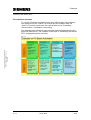
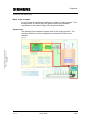
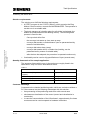
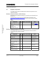
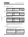
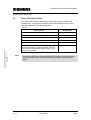
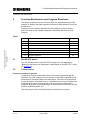
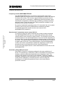
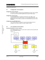
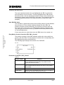
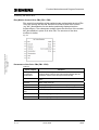
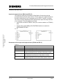
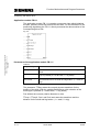
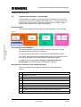
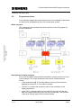
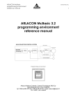
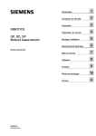
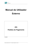
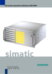
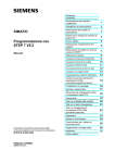
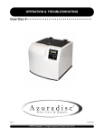
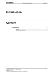
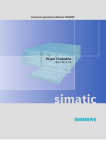
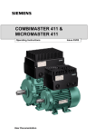
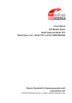
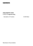
Application for Drive Technology PC-based automation with SIMATIC WinAC Positioning with WinAC RTX, Easy Motion Control and MICROMASTER 4xx Preamble Positioning with WinAC RTX Preamble Foreword The SIMATIC Windows Automation Center (WinAC) offers an open, extensive and robust basis to realize your PC-based automation solution. Because of full compatibility to SIMATIC S7 in combination with interfaces to the (open) PC world, you can combine your classic automation tasks with the possibilities of the PC world. The use of SIMATIC industry PCs offers a powerful and robust platform for your automation solution with WinAC. Arrangement of the examples The automation tasks which are described in the examples are oriented to the typical fields of use of the automation technology. 21004767 Copyright Siemens AG 2004 All rights reserved 21004767_WinAC_TK_DOKU_v10_e.doc Eight examples have been developed for the quick entry into the PC based automation with SIMATIC WinAC. They consist of example code and an extensive documentation. Using these examples you as a user can familiarize with the particular themes considering the particular tasks. V 1.0 • Control • Communication • Visualization • Technology 28.07.2004 2/49 Preamble Positioning with WinAC RTX The individual examples To use the PC based automation in the most efficient way, we developed one example from the “classic” SPS world and one example from the “open” PC world for each of the four typical fields of use (controlling, communication, visualization, technology). The following figure shows all eight examples with their assignment to the particular fields of use. The example on the topic of “positioning with WinAC RTX” is highlighted with a red frame. 21004767 Copyright Siemens AG 2004 All rights reserved 21004767_WinAC_TK_DOKU_v10_e.doc Fig. 1-1 V 1.0 28.07.2004 3/49 Preamble Positioning with WinAC RTX Basis of the examples As a joint topic all examples are based on a fictitious “mixing process”. This mixing process is used to apply the different tasks and automation components of the product range of PC based automation. System view The following figure shows the system view of the “mixing process”. The red frame shows you which components are described in the current example. 21004767 Copyright Siemens AG 2004 All rights reserved 21004767_WinAC_TK_DOKU_v10_e.doc Fig. 1-2 V 1.0 28.07.2004 4/49 Warranty, Liability and Support Positioning with WinAC RTX Warranty, Liability and Support Any claims against us - based on whatever legal reason - resulting from the use of the examples, information, programs, engineering and performance data etc., described in this document shall be excluded. Such an exclusion shall not apply in the case of mandatory liability, e.g. under the German Product Liability Act (“Produkthaftungsgesetz”), in case of intent, gross negligence, or injury of life, body or health, guarantee for the quality of a product, fraudulent concealment of a deficiency or breach of a condition which goes to the root of the contract (“wesentliche Vertragspflichten”). However, claims arising from a breach of a condition which goes to the root of the contract shall be limited to the foreseeable damage which is intrinsic to the contract, unless caused by intent or gross negligence or based on mandatory liability for injury of life, body or health. The above provisions does not imply a change in the burden of proof to your detriment. The Application Examples are not binding and do not claim to be complete regarding the circuits shown, equipping and any eventuality. They do not represent customer-specific solutions. They are only intended to provide support for typical applications. You are responsible in ensuring that the described products are correctly used. 21004767 Copyright Siemens AG 2004 All rights reserved 21004767_WinAC_TK_DOKU_v10_e.doc We do not accept any liability for the information contained in this document. These Application Examples do not relieve you of the responsibility in safely and professionally using, installing, operating and servicing equipment. When using these Application Examples, you recognize that Siemens cannot be made liable for any damage/claims beyond the liability clause described above. We reserve the right to make changes to these Application Examples at any time without prior notice. If there are any deviations between the recommendations provided in these Application Examples and other Siemens publications - e.g. Catalogs - then the contents of the other documents have priority. Copyright© 2004 Siemens A&D. It is not permissible to transfer or copy these Application Examples or excerpts of them without first having prior authorization from Siemens A&D in writing. For questions about this document please use the following e-mail-address: [email protected] V 1.0 28.07.2004 5/49 Table of Contents Positioning with WinAC RTX 21004767 Copyright Siemens AG 2004 All rights reserved 21004767_WinAC_TK_DOKU_v10_e.doc Table of Contents 1 Task Specification .......................................................................................... 7 2 2.1 2.2 2.3 Principle of the Automation Solution............................................................ 9 Display of components ..................................................................................... 9 Required components..................................................................................... 10 Basic Performance Data................................................................................. 13 3 3.1 3.2 3.3 3.4 3.5 3.6 3.7 Function Mechanisms and Program Structures ........................................ 14 WinAC RTX basics ......................................................................................... 14 Further basics ................................................................................................. 14 Configuration of the hardware ........................................................................ 17 Core elements of this solution ........................................................................ 17 Logical core structures – An example............................................................. 22 Program structures ......................................................................................... 23 Program sequence ......................................................................................... 24 4 4.1 4.2 4.2.1 4.2.2 4.2.3 4.3 4.4 4.5 Hardware and Software Installation ............................................................ 28 Preparatory installation ................................................................................... 28 Hardware configuration................................................................................... 30 Industry PC / WinAC (Station 1) ..................................................................... 30 ET200S Station (Station 2) ............................................................................. 30 MICROMASTER 440 (Station 3) and Motor ................................................... 31 Installation of the WinAC RTX Software ......................................................... 39 Use of WinAC RTX ......................................................................................... 39 Configuration of the automation stations ........................................................ 39 5 Operator control and monitoring ................................................................ 43 6 Bibliography.................................................................................................. 49 V 1.0 28.07.2004 6/49 Task Specification Positioning with WinAC RTX 1 Task Specification Task specification/ overview In the WinAC, the position control is realized by means of the Easy Motion Control modules. The positioning signals which are necessary for the inverter are sent via the PROFIBUS. At the motor there is an incremental shaft encoder by means of which a detection of the current motor speed and axis position is carried out. The encoder detection is located on the distributed I/O module ET200S which communicates with the WinAC via the PROFIBUS and so delivers the actual value of the position for the control. Principle view of the automation solution Fig. 1-1 21004767 Copyright Siemens AG 2004 All rights reserved 21004767_WinAC_TK_DOKU_v10_e.doc The following figure shows the interaction of the automation components, which are described in this example, in principle. V 1.0 28.07.2004 7/49 Task Specification Positioning with WinAC RTX Solution requirements 21004767 Copyright Siemens AG 2004 All rights reserved 21004767_WinAC_TK_DOKU_v10_e.doc The solution must fulfill the following requirements: • A STEP7 program in the S7-CPU (WinAC), which contains the Easy Motion Control modules, controls the MICROMASTER. The operation is carried out via a variable table. • The bottle transport of a bottling plant for soft drinks is simulated (the bottles are positioned below the bottling device). The following basic process is used for that: • – Conveyor belt still at first – the conveyor belt starts up via a start up ramp – conveyor belt travels a certain distance (can be parameterized by means of variable table) – conveyor belt slows down (ramp) – conveyor belt stands still for a certain time (bottling, can be parameterized by means of variable table) – after the time has elapsed, the procedure is repeated continuously functionality can be used on big specifications of input (several axes) Quantity framework of the sample application: The amounts of data which occur in the project are roughly listed in the table below. Only one axis is described at a time. Table 1-1 Criteria Basic data of the line Amount of data (Easy Motion Control and user program) approx. 1kByte Load memory requirement 34 Kbytes User memory requirement 24 Kbytes Transmission rates (PROFIBUS) 1.5 Mbit/s Customer advantage Compared to the classical positioning tasks, which are carried out without a PC, the customer has the following advantages with this solution: • • • V 1.0 fast processing of the positioning tasks even with several axes simultaneous visualization of the control (control and visualization in one device) in case the communication of the I/Os allows it, approximately five times more axes can be used compared to hardware controllers. 28.07.2004 8/49 Principle of the Automation Solution Positioning with WinAC RTX 2 Principle of the Automation Solution The hardware structure of the automation solution is described in this chapter. The respectively necessary hardware and software components are listed in a table in chapter 2.2 Required components. 2.1 Display of components The following figure shows the hardware setup of the sample application and the standard and user software components involved. 21004767 Copyright Siemens AG 2004 All rights reserved 21004767_WinAC_TK_DOKU_v10_e.doc Fig. 2-1 V 1.0 28.07.2004 9/49 Principle of the Automation Solution Positioning with WinAC RTX 2.2 Required components The tables below contain the hardware and software components for the respective stations. Hardware components Station 1 (WinAC Station) Any other (current) Siemens industry PC can also be used alternatively as industry PC. The given FAQs can be found on the A&D Support Homepage under http://support.automation.siemens.com (enter the FAQ ID into the search field). Table 2-1 21004767 Copyright Siemens AG 2004 All rights reserved 21004767_WinAC_TK_DOKU_v10_e.doc Component Qty. MLFB / Order number Industry PC SIMATIC Rack PC IL 40 S 1 6AG4011-0CA21-0JX0 Communications processor CP 5613 A2 for PROFIBUS, PCI-card 1 6GK1 561-3AA00 Note configurator: see FAQ ID 17128155 Hardware components Station 2 (S7-ET200S) The ET200S station can be of any type because the counter module is supported by every interface module. Table 2-2 Component V 1.0 Qty. MLFB / Order number Note Power Supply PS 307 2A 1 6ES7 307-1BA00-0AA0 Adapter for standard mounting rail 1 6ES7 390-6BA00-0AA0 Top hat rail 500mm 1 8GR4 926 IM 151-1 1 6ES7 151-1AA01-0AB0 to be mounted on top hat rail Terminal module (for Power module) TMP15S23-A1 1 6ES7 193-4CC20-0AA0 to be mounted on top hat rail Terminal module (for Counter module) TME15S24-01 1 6ES7 193-4CB20-0AA0 to be mounted on top hat rail Power module PM-E DC24V 1 6ES7 138-4CA00-0AA0 Counter module 1Count 24V/1024 increments 1 6ES7 138-4DA03-0AB0 28.07.2004 for mounting onto the top hat rail 10/49 Principle of the Automation Solution Positioning with WinAC RTX Hardware components Station 3 (MICROMASTER 440) Table 2-3 Qty. MLFB / Order number MICROMASTER 440 1 6SE6440-2UC12-5AA1 PC inverter connection block 1 6SE6400-1PC00-0AA0 MICROMASTER 4 PROFIBUS MODUL 1 6SE6400-1PB00-0AA0 Note is not required if the PG has a PROFIBUS connection or the CPU is routing capable Precondition is a serial interface at the PC. Hardware components for the motor Table 2-4 Component 21004767 Copyright Siemens AG 2004 All rights reserved 21004767_WinAC_TK_DOKU_v10_e.doc Component V 1.0 Qty. MLFB / Order number Note Standard asynchronous motor 120W 1 1LA7060-4AB10-Z options A23 Option A23 enables a motor temperature evaluation. You can find detailed information in the user manual of the MICROMASTER in chapter 3.21 Incremental encoder 1024 increments / 24V 1 1XP8001-1 Is screwed in. Any other encoder with 24V voltage, 1024 increments and 2 ways (direction recognition) which are permitted for the used motor can be used alternatively 28.07.2004 11/49 Principle of the Automation Solution Positioning with WinAC RTX Hardware components for the PG/PC Table 2-5 Component Qty. Programming device Power PG 1 MLFB / Order number 6ES7 750-2CA52-4FB4 Note configurator: see FAQ ID 17128155 CP 5611 integrated Software components on the SIMATIC PC-Station (Station 1) Table 2-6 Qty. MLFB / Order number SIMATIC WinAC RTX V4.1 1 6ES7 671-0RC04-0YA0 Easy Motion Control V2.0 6ES7 864-0AC01-0YX0 1 Note SIMATIC NET CD is contained in the WinAC package. Software components on the PG/PC Table 2-7 21004767 Copyright Siemens AG 2004 All rights reserved 21004767_WinAC_TK_DOKU_v10_e.doc Component Component Qty. MLFB / Order number Note STEP 7 V5.3 1 6ES7 810-4CC07-0YA5 STARTER V3.0 1 Pro Tool/Pro V6.0+SP2 1 6AV6 582-2BX06-0CX0 Optional Drive ES 1 6SW1 700-0JA00-0AA0 Optional Can be downloaded under Entry ID 13336809 Alternatively to the given configuration, Pro Tool/Pro can be used for operator control and monitoring instead of a variable table. With Drive ES an easy integration of the motor parameterization into STEP 7 can be realized. Example project The example application consists of the following components. Further information on commissioning hardware and software is available in chapter 4 Hardware and Software Installation. Table 2-8 Component V 1.0 Note 21004767_WinAC_TK_CODE_v10.zip This packed file contains the full code and the configuration for this application. 21004767_WinAC_TK_DOKU_v10_d.pdf This document 28.07.2004 12/49 Principle of the Automation Solution Positioning with WinAC RTX 2.3 Basic Performance Data The table below informs about basic data of the system software and configuration. You get an overview on the powerful performance of this example application and its components. Table 2-9 Note 21004767 Copyright Siemens AG 2004 All rights reserved 21004767_WinAC_TK_DOKU_v10_e.doc Characteristic V 1.0 WinAC RTX Load memory requirement for EMC modules Approx. 25 Kbytes Main memory requirement for EMC modules Approx. 21 Kbytes Local files of the EMC modules Approx. 324 bytes Load memory requirement for application Approx. 2 Kbytes Main memory requirement for application Approx. 1.5 Kbytes Total time for the execution of the EMC modules in the example program (without application modules, with one axis) measured with WinAC RTX V4.1 on Athlon with 1333 MHz 162 µs (typical value) The performance of the desired positioning orientates on the processor used in the industry PC, the used I/Os and the basic communication speed. 28.07.2004 13/49 Function Mechanisms and Program Structures Positioning with WinAC RTX 3 Function Mechanisms and Program Structures The basics as well as the use of WinAC RTX are described shortly in this chapter. In addition the basic operation principle of Easy Motion Control will be looked at. Furthermore, this chapter describes the Easy Motion Control modules which are used in this example application and deals with their special features. Topics 21004767 Copyright Siemens AG 2004 All rights reserved 21004767_WinAC_TK_DOKU_v10_e.doc Chap. 3.1 Title Page 3.1 WinAC RTX basics 14 3.2 Further basics 14 3.3 Configuration of the hardware 17 3.4 Core elements of this solution 17 3.5 Logical core structures – An example 22 3.6 Program structures 23 3.7 Program sequence 24 WinAC RTX basics You can find the basics to WinAC RTX in chapter 3 in the application "Basics for the Solution of Automation Tasks Based on WinAC RTX " (entry ID: 21004765). 3.2 Further basics Frequency inverters in general A frequency inverter enables the control of the motor speed through the frequency (f) of the voltage (U) or the current on the basis of special power electronics in connection with a microprocessor. The ratio U/f (proportional n) can be kept on a constant level or a calculated current can be made load independent by which a very precise electronic control of the speed is achieved. By means of this technology, an asynchronous motor can now be used for positioning tasks, too. The frequency inverter will subsequently be referred to as inverter. V 1.0 28.07.2004 14/49 Function Mechanisms and Program Structures Positioning with WinAC RTX Frequency inverter MICROMASTER 440 The MICROMASTER 440 is an inverter for three-phase motors with additional speed and torque control. A microprocessor controls the different functions of the motor. The inverter supports different processes for the control of the motor. Furthermore, it additionally features automatic motor identification mechanisms, different logic interlinking, protective functions and much more. There are more than 3000 parameters available for the handling of this variety of functions. By means of attachable operating panels, PC connection kits or bus option modules, the inverter can be parameterized, tested and operated. For detailed information please see the user manual of the MICROMASTER (chapter 8). In modern inverters the speed controllers are usually already integrated. The MICROMASTER 440 uses a so called field oriented vector control (shortly called: vector control) for speed control. The principle of the vector control is based on the load-independence of a motor current depending on the motor flow in a way that subsequently the desired torque is achieved at the motor. The speed would be slowed down to the desired value in spite of a higher load on the axis. For the determination of the load-independent current, the inverter uses different mathematic algorithms as well as the theoretical motor model determined by the motor identification. 21004767 Copyright Siemens AG 2004 All rights reserved 21004767_WinAC_TK_DOKU_v10_e.doc Speed control / sensorless vector control (SLVC) For the use of this speed control a motor identification must be done in the MICROMASTER. Overview on Easy Motion Control Easy Motion Control is a software package for the easy positioning of drives. The positioning is realized by means of a software controller which enables a precise positioning (depending on the hardware used). The control of the position is only done by the software. There is no special hardware necessary for the connection of I/Os. The MICROMASTER 440 could also be replaced by conventional power units but offers the advantage of an additional speed and torque control and different protective functions. V 1.0 28.07.2004 15/49 Function Mechanisms and Program Structures Positioning with WinAC RTX Functions of Easy Motion Control • Jogging • Reference point approach • Positioning absolute/relative • Electronic drive • Reference point setting • All standard monitoring functions for positioning • Speed-overdrive • Position control • Simulation • Preassembled input and output drivers for encoder or analogue output modules Components of Easy Motion Control The following components are delivered together with Easy Motion Control. 21004767 Copyright Siemens AG 2004 All rights reserved 21004767_WinAC_TK_DOKU_v10_e.doc Basically Easy Motion Control offers the following functions: Fig. 3-1 V 1.0 28.07.2004 16/49 Function Mechanisms and Program Structures Positioning with WinAC RTX 3.3 Configuration of the hardware Configuration of the controller The WinAC is being configured with a PROFIBUS processor which enables the communication to the MICROMASTER and the ET200S station. Configuration of the inverter The MICROMASTER is configured as DP Slave in the STEP 7 and parameterized with the address which is set at the MICROMASTER. (The address is set on the switch on module of the PROFIBUS by means of DIL switches.) Configuration of the ET200S Station 3.4 21004767 Copyright Siemens AG 2004 All rights reserved 21004767_WinAC_TK_DOKU_v10_e.doc The ET200S Station is configured as slave and the address which is configured in the HW-Config is set at the interface module. Core elements of this solution Important Easy Motion Control modules In the following figure you can see the basic modules and the principal data flow of Easy Motion Control. Abbildung 3-2 V 1.0 28.07.2004 17/49 Function Mechanisms and Program Structures Positioning with WinAC RTX The most essential module is the red highlighted axis DB. It contains the axis information of one axis each. The blue highlighted drive FBs access this data module. Also the peripheral modules and the control modules (all displayed in yellow) use the axis DB for their tasks. The peripheral modules are preassembled modules for the easy connection of input and output periphery. Axis DB (DB1 Axis) The axis DB is a global data module which all Easy Motion Control Modules have access to. It is the central interface between the drive FBs, the position controller and the peripheral (I/O) modules of one axis each. All data of this axis is stored in it. It is differentiated between parameter data (e.g. axis type), the current data (e.g. position-actual value) and the errors (or acknowledgements). If more axes are to be used, then more axis DBs have to be created, too. The position controller of the EMC software realizes the values which are given by the drive FBs. For this purpose it accesses the corresponding axis DB (displayed as yellow module above). The following figure displays the module in the FUP/KOP. 21004767 Copyright Siemens AG 2004 All rights reserved 21004767_WinAC_TK_DOKU_v10_e.doc Easy Motion Control Controller (FB11 MC_Control) Fig. 3-3 Parameter of the FB11, MC_Control Table 3-1 Input / output V 1.0 Function Axis With the two inputs axis the connection to the corresponding axis is realized (through axis DB). Every EMC function module has these two inputs. Init Init provides an initializing bit of the corresponding axis DB (each module needs an exclusive bit which is only used by this module). EnableDrive Release of the axis DriveEnabled With the output DriveEnabled the status of the controller is given back. This bit is set if there is no error. 28.07.2004 18/49 Function Mechanisms and Program Structures Positioning with WinAC RTX Easy Motion Control Drive FBs (FB1...FB5) The special functionalities of the positioning are realized with the drive FBs. They also access the axis DB. Each drive FB has a fixed drive function (e.g. MC_MoveRelative for the relative positioning displayed as blue module above). The subsequent module shows the structure of the module MC_MoveRlative in place of all drive FBs. The structure of the other modules is similar. 21004767 Copyright Siemens AG 2004 All rights reserved 21004767_WinAC_TK_DOKU_v10_e.doc Fig. 3-4 Parameters of the Drive FBs (FB1...FB5) Table 3-2 Input / output V 1.0 Function Velocity, Acceleration, Deceleration Definition of velocity, acceleration and deceleration. In our example these values have been parameterized with the maximum values of the axis (from the axis DB). Distance Specification of the relative distance to drive to the current point. Execute Start of the drive job. Busy The output Busy is set when the drive job is being executed. Done Display that the job has been executed. (Is only set shortly). CommandAborted, Error Error report (see manual Easy Motion Control) Axis See above (MC_Control). Init See above (MC_Control). 28.07.2004 19/49 Function Mechanisms and Program Structures Positioning with WinAC RTX Input and output drivers (FB 26 and FB 37) The data can easily be processed in Easy Motion Control through the preassembled input and output drivers. These drivers are again at hand as function modules and can be integrated into a STEP 7 project, if needed. The driver modules displayed below represent the input and output drivers of our example. The two modules are used: • Input driver encoder ET200S1 Count (for counter module in a ET200S) and • Output driver OutputMM4_DP (PROFIBUS switch-on module for MICROMASTER 440). 21004767 Copyright Siemens AG 2004 All rights reserved 21004767_WinAC_TK_DOKU_v10_e.doc Fig. 3-5 Parameters of the input and output drivers (FB 26 and FB 37) Table 3-3 Input / output V 1.0 Function Axis See above (MC_Control). Init See above (MC_Control). EnableDrive Release of the output periphery. This input is linked with the output DriveEnabled of the controller module MC_Control. DOut_1, DOut_2, DIn Digital inputs and outputs (remain free in the example and are addressed internally by the Easy Motion Control) EncErr, OutErr Error treatment inputs and outputs (are not needed). For detailed explanations see manual of Easy Motion Control. 28.07.2004 20/49 Function Mechanisms and Program Structures Positioning with WinAC RTX Application module FB 111 The application module FB 111 contains a sequence chart which initializes the axis, positions it and sets it back into idle state. For the realization of the positioning algorithms the FB 111 directly accesses the data modules of the corresponding drive FBs. Parameters of the application module FB 111 21004767 Copyright Siemens AG 2004 All rights reserved 21004767_WinAC_TK_DOKU_v10_e.doc Fig. 3-6 Table 3-4 Input / output Function TTstay Specification of the desired stand time for the bottling of the drink. BottleSize With the variable BottleSize a quick selection of the bottle type is possible (0 = small bottle, 1 = big bottle). TTstay1, TTstay2, Pos1, Pos2 TTstay1, TTstay2, Pos1 and Pos2 each state the stand time and the distance for the small and big bottles. (1 = small, 2 = big). The parameter TTStay states the currently chosen stand time for the bottling of the drink. With the variable BottleSize a quick selection of the bottle type is possible (0 = small bottle, 1 = big bottle). Pos defines the currently relative distance to drive. TTstay1, TTstay2, Pos1 and Pos2 each state the stand time and the distance for the small and big bottles. (1 = small, 2 = big). V 1.0 28.07.2004 21/49 Function Mechanisms and Program Structures Positioning with WinAC RTX 3.5 Logical core structures – An example In this example it is shown in an easy way how a position control can be realized by means of the software SPS WinAC V4.1. For this purpose the motor of the conveyor belt, for the bottles which are to be filled, ought to position one bottle at a time under the bottling jet. Data flow model The following graphic illustrates the important data flows in this example. The meaning of the parameters The setpoint position gives the position desired by the user. It can be transmitted relatively as well as absolutely. 21004767 Copyright Siemens AG 2004 All rights reserved 21004767_WinAC_TK_DOKU_v10_e.doc Fig. 3-7 The speed which is necessary for the motor is called setpoint speed. The actual value serves for the determination of the current position of the axis and is the basis for the recalculation of the setpoint speed. In addition, also the parameters velocity, acceleration and axis deceleration can be transmitted to the position controller. Description of processes in the example program The basic process of the example is described in the table below. Table 3-5 No. V 1.0 Action 1 Initialization of the axis 2 Release of the axis 3 Transmission of the setpoint position to the position controller 4 Calculation of the setpoint speed 5 Reading of the actual position of the axis through the encoder 6 Calculation of the deviation of the setpoint position from the actual position 7 Transmitting the new setpoint speed to the inverter 8 Repeat from step 5 and on until the setpoint position is achieved 9 On from step 3 28.07.2004 22/49 Function Mechanisms and Program Structures Positioning with WinAC RTX 3.6 Program structures In the following chapter the setup and structure of the example is discussed on the function and datablock level of the automation system. Block structure The subsequent figure shows the module structure of the S7 program on the two controllers. 21004767 Copyright Siemens AG 2004 All rights reserved 21004767_WinAC_TK_DOKU_v10_e.doc Fig. 3-8 Description of module structure For a quick illustration of principal functionalities, a simple structure is used in this example. The rough module structure can be characterized as follows: V 1.0 • In the timed alarm OB 35 the Easy Motion Control modules and the application module FB 111 are called cyclically. • The SB 111 contains the sequence chart for the realization of the bottling application. • In the FB 111 the data module of the drive FBs as well as of the axis DBs is accessed depending on the current process step. The functions of the drive FBs are called via their data modules. 28.07.2004 23/49 Function Mechanisms and Program Structures Positioning with WinAC RTX 3.7 Program sequence Subsequently the S7 program is described, which provides the bottling application in the WinAC. The complete Easy Motion Control program is basically carried out in a timed alarm OB (in this case OB35). Program flow chart Subsequently the S7 program is described, which provides the bottling application in the WinAC. The complete Easy Motion Control program is basically carried out in a timed alarm OB (in this case OB35). Table 3-6 Description An axis initialization is done depending on the status of the system (in case of restart, reset, or error). Reading of the encoder values via the ET200S. 21004767 Copyright Siemens AG 2004 All rights reserved 21004767_WinAC_TK_DOKU_v10_e.doc Flowchart Calling the application module (execution of the sequence chart). Providing the jog function. Providing the relative motion. Providing the zero point synchronization functions. Calling the possible stop functions. Controlling the motor periphery. V 1.0 28.07.2004 24/49 Function Mechanisms and Program Structures Positioning with WinAC RTX Sequence chart of the user module FB 111 (Application) For the execution of the bottling application in the module FB 111 a sequence chart was programmed in STEP7 which is described subsequently: Table 3-7 21004767 Copyright Siemens AG 2004 All rights reserved 21004767_WinAC_TK_DOKU_v10_e.doc No. Name of the step 1 SInit Initialization step 2 SAxisFree Axis release 3 SErrorAck Error acknowledgement after initialization 4 SHpos Positioning by hand 5 SHome Reference point setting 6 SInitFilling Initialization of the bottling process (time and position are transferred into the variables TTstay and pos in dependence of the bottle size). 7 SFill Bottling step (simulation of the bottling process with a timer) 8 SPlacing Positioning with the module MC_Move Relative. The conveyor belt is moved forward over a predefined distance (depending on the bottle size). 9 SAxisRun Axis is in motion 10 SAxisReady V 1.0 Action Axis has arrived destination 28.07.2004 25/49 Function Mechanisms and Program Structures Positioning with WinAC RTX Code excerpt from the application module with the positioning request The following code excerpt from the FB 111 shows step eight of the sequence chart, which realizes the positioning of the axis in form of a data module access. Network 8: Schritt 8 / stepp 8 (SPlacing) U T1 21004767 Copyright Siemens AG 2004 All rights reserved 21004767_WinAC_TK_DOKU_v10_e.doc S "SPlacing" U( O "DB_MC_MoveRelative".Done O "Halt" O "Reset" ) R "SPlacing" U "SPlacing" = L 0.0 U L 0.0 SPBNB _005 L #pos T "DB_MC_MoveRelative".Distance _005: NOP 0 U L 0.0 BLD 102 = "DB_MC_MoveRelative".Execute // // // // Wenn Timer 1 abgelaufen ist If timer 1 has gone off aktiviere Schritt 8 (Positionieren) activate step 8. // // // // Rücksetzung erfolgt über Schritt 10 The step 8 is resetting by the step 10 oder Halt, / the Reset or the Halt flag. bzw. Reset // // // // // // // // // // Wenn Schritt 8 (Positionieren) aktiv ist If step 8 is active dann lade die relative Fahrweite in den Datenbaustein des FahrFB´s MC_MoveRealative then transfer the relative move wide into the move FB MC_MoveRealative und setze den Eingang Execute am DB zum Starten der Positionierung and set the execute flag at the FB MC_MoveRealative Description of the positioning request After step 7 (bottling/SFilling) and the finishing of the timer step 8 is started. In this step the relative distance to the next point is written into the data module of the FB_MoveRelative. In the same way the drive process is started in the data module by means of the Execute bit. V 1.0 28.07.2004 26/49 Function Mechanisms and Program Structures Positioning with WinAC RTX Code excerpt of the OB35 with the call for the drive FBs MC_MoveJog 21004767 Copyright Siemens AG 2004 All rights reserved 21004767_WinAC_TK_DOKU_v10_e.doc The following code excerpt represents the call for the drive FB’s MC_MoveJog in the OB35 as well as its parameter transfer. Netzwerk 4: Handbetrieb / manual funktion CALL "MC_MoveJog" , "DB_MC_MoveJog" // Aufruf des Tipp-Funktionsbausteins MC_MoveJog // Call of the Jog FB. JogPos := JogNeg := Velocity :="Axis".Ax.MaxVelocity // Setzen der Geschwindigkeit auf die maximal zu// lässige Achsgeschwindigkeit // Set the velocity to the most permitted axis // velocity. Acceleration :="Axis".Ax.MaxAcceleration // Setzen der Beschleunigung auf die // maximal zulässige Achsbeschleunigung // Set the acceleration to the most permitted axis // acceleration. Deceleration :="Axis".Ax.MaxDeceleration // Setzen der Verzögerung auf die maxi// mal zulässige Achsverzögerung // Set the deceleration to the most permitted axis // deceleration. Busy := Done := CommandAborted:= Error := Axis :="Axis".Ax // Zuweisung der Achse // Assignment of the axis Init :="Axis".Ax.Init.I2 // Zuweisung des Initialisierungsbits // Assignment of the initialization flag. NOP 0 Description of the positioning request The code excerpt is an example for the call of the positioning module for the jog mode (manual axis movement). As mentioned above, the maximum permissible values for the movement parameters velocity, acceleration and deceleration of the axis have been transferred to the axis DB. With Axis the axis which is to be used is transferred to the DB1 ("Axis") by means of the corresponding axis DB. An initializing bit of the axis DB is assigned to the variable Init. Therefore it is essential that the bit is assigned only once. Each Easy Motion Control function module has its own initializing bit. It is not allowed to double-assign any initializing bits! All other drive FBs are parameterized in the same way. V 1.0 28.07.2004 27/49 Hardware and Software Installation Positioning with WinAC RTX 4 Hardware and Software Installation This chapter describes the installation of the components for the application. It is divided into the following sections. Topics Chap Title Page 4.1 Preparatory installation 28 4.2 Hardware configuration 30 4.3 Installation of the WinAC RTX Software 39 4.4 Use of WinAC RTX 39 4.5 Configuration of the automation stations 39 The following table shows important installation and set up orders for the commissioning of the application. Table 4-1 No. 21004767 Copyright Siemens AG 2004 All rights reserved 21004767_WinAC_TK_DOKU_v10_e.doc Installation order 4.1 Action 1 STEP 7 V5.2 SP1 (or higher) 2 SIMATIC NET PC Software V6.1 SP1 (or higher) 3 Installation of the parameterization software STARTER or Drive ES 4 Installation of the CP5613 A2 5 Installation of the hardware for Station 2 (ET200S) and Station 3 (MICROMASTER 440) 6 WinAC RTX V4.1 (or higher) This installation is divided into the following steps: • Installation and checking of the VenturCom RTX extensions • Installation and authorization of the software WinAC RTX Preparatory installation STEP 7 Step 7 is installed on the PG/PC which is provided for the configuration and programming of the automation station. Alternatively STEP 7 can also be installed on the PC (Station 1) on which WinAC ought to run. At this point, we will not go further into the installation of STEP7. The installation takes place in the familiar Windows environment and is selfexplanatory. V 1.0 28.07.2004 28/49 Hardware and Software Installation Positioning with WinAC RTX SIMATIC NET PC Software The SIMATIC NET PC software is installed on the PC (Station 1) on which subsequently also the WinAC ought to be installed. The software package contains all needed aids for the installation and the operation of a PC station. From the STEP 7 Version 5.2 upward, the process “Advanced PC Configuration” is used for the commissioning of PC stations. This enables the configuration of PC stations directly in STEP 7. Before the use of “Advanced PC Configuration” it is highly recommended to read the manual /2/ “SIMATIC NET, Commissioning of PC stations—instructions and quick start”. Starter installation For the parameterization of the inverter the software "Starter“ or alternatively the tool Drive ES is needed. The installation is processed in the standard Windows setup order. Installation of the Easy Motion Control software For the parameterization of the axis and for the programming you need the Easy Motion Control software. 21004767 Copyright Siemens AG 2004 All rights reserved 21004767_WinAC_TK_DOKU_v10_e.doc Please install one of the two packages on your PC/PG. The installation of the software is processed in the standard Windows setup order. Note V 1.0 Because the Easy Motion Control modules have to be licensed, they will not be delivered together with the project. The project can only be processed if Easy Motion Control has been installed. 28.07.2004 29/49 Hardware and Software Installation Positioning with WinAC RTX 4.2 Hardware configuration The basic hardware configuration can be seen in chapter 2.1. 4.2.1 Industry PC / WinAC (Station 1) Please see the application "Basics for the Solution of Automation Tasks Based on WinAC RTX " (entry ID: 21004765) for information on the hardware setup and on the commissioning of the industry PC. 4.2.2 ET200S Station (Station 2) Hardware setup of the ET200S Station (Station 2) 21004767 Copyright Siemens AG 2004 All rights reserved 21004767_WinAC_TK_DOKU_v10_e.doc Table 4-2 No. Action 1 The power supply is mounted onto the top-hat rail by means of the top-hat rail adapter. 2 The interface module is mounted next to the power supply on the top-hat rail. 3 Then the two terminal modules and on top of each the power and the counter module are installed. The power module is snapped on left of the counter module. See the manual ET 200S (Entry ID 1144348) and ET200S Technological Manual (Entry ID 9264111) for detailed installation instructions. 4 Supply the interface module with the operating voltage. 5 Connect the power module to the power supply as follows. • Pin 2 with +24V DC (L+) • Pin 3 with 0 V DC (M) 6 Set the address 7 at the interface module with the help of the DIL switch. (set bit 1, 2 and 3) 7 Connect the ET200S (Station 2) to the industry PC (Station 1) by means of the PROFIBUS cable. Pay attention to the terminating resistor. 8 Connect the encoder to the counter module with enough cable as it is described in the following table. Wiring of the ET200S Station (Station 2) Table 4-3 Signal V 1.0 24 V encoder (plug name) Wire color 1Count Ua1 E yellow Channel A (Pin 5TM) Ua2 H pink Channel B (Pin 1TM) 0V (M) K grey 0V (Pin 7 TM) Up(24V DC) M black/white 24V (Pin 6 TM) 28.07.2004 30/49 Hardware and Software Installation Positioning with WinAC RTX ! Attention The wiring table must be harmonized with the hardware at site. Before taking into operation, please make sure that the wiring mentioned above is permissible for your hardware, using the manual, because wrong wiring could lead to errors or destruction of the hardware. Commissioning of the ET200S Station (Station 2) After switching on the voltage, the ON LED of the interface module should light up. On the power module the ON LED should light up. 4.2.3 MICROMASTER 440 (Station 3) and Motor Wiring scheme (overall) 21004767 Copyright Siemens AG 2004 All rights reserved 21004767_WinAC_TK_DOKU_v10_e.doc Fig. 4-1 Wiring table MICROMASTER and motor Table 4-4 Signal V 1.0 MM 440 Motor 230V AC-P L 230V AC-N N PE PE PE Inverter output U U1 Inverter output V V1 Inverter output W W1 28.07.2004 31/49 Hardware and Software Installation Positioning with WinAC RTX Set up MM 440 and motor Table 4-5 21004767 Copyright Siemens AG 2004 All rights reserved 21004767_WinAC_TK_DOKU_v10_e.doc No. Action 1 Connect the MICROMASTER 440 to the voltage supply, like it is shown in the wiring table. 2 Now connect the MICROMASTER to the motor, like described above. 3 Clamp the motor into triangle changeover in the clamping box. (see operating instructions MICROMASTER 440) 4 Install the PROFIBUS switch-on by snapping the option module onto the MICROMASTER. 5 Set the address of the module to the value 15 (switch bit 1, 2, 3 and 4 to ON) by means of the DIL switches. 6 Connect the MICROMASTER (Station 3) to the industry PC (Station 1) by means of the PROFIBUS cable. Pay attention to the terminating resistors. 7 If there is no PROFIBUS interface at the PG and the SIMATIC controller is not routing capable, the PC inverter connection set can be snapped onto the PROFIBUS option module additionally. 8 Install the encoder at the motor as it is shown in the supplied manual. Parameterization and commissioning of the MICROMASTER with STARTER Because the parameterization by means of Drive ES is almost similar to the parameterization with STARTER, only the process with STARTER is described here. If your PG/PC has a PROFIBUS interface, the parameterization of the inverter can be carried out via the PROFIBUS. As an alternative you need a serial interface and the PC-inverter connection kit by which you can connect it to the MICROMASTER. Table 4-6 No. Action 1 Connect your PG to the MICROMASTER PROFIBUS option module via the PROFIBUS. Alternatively via the serial interface (with the PC-inverter connection kit). 2 Start the program STARTER (double click on the desktop icon or under ”START Æ SIMATIC Æ STARTER“) V 1.0 28.07.2004 32/49 Hardware and Software Installation Positioning with WinAC RTX 3 21004767 Copyright Siemens AG 2004 All rights reserved 21004767_WinAC_TK_DOKU_v10_e.doc If the wizard is not displayed automatically you can call it up in the menu “Project Æ New with Wizard“. 4 Select “Find drive units online…” 5 Enter the desired project name. If you want you can also change the clipboard account and fill out the other fields. Complete the step with “Next”. 6 Click on Change and Test… to select the interface. 7 If you use the PC-inverter connection kit, select the “PC COM-PORT (USS)” and set the communication parameters suitable for you with Properties. Under baud rate test you can define which baud rate is set at the MICROMASTER. Set the same baud rate for the interface as was determined for the inverter. Please set to the PROFIBUS interface in the dialogue field for the use of the PROFIBUS interface. Acknowledge with “OK” and then click on “Next”. V 1.0 28.07.2004 33/49 Hardware and Software Installation Positioning with WinAC RTX 8 Click on “Search for reachable nodes”. Select “Drive unit_Adr0”, click on “Next” and then on “Complete”. Go online by clicking on this button. 21004767 Copyright Siemens AG 2004 All rights reserved 21004767_WinAC_TK_DOKU_v10_e.doc 9 10 Restore the factory settings by right clicking on “Drive unit_Adr0 Æ Target system Æ Restore factory settings“. Acknowledge with OK. 11 If you use the PC-inverter connection kit it is recommended to raise the baud rate. • Double click on “Clamp/Bus” in the tree diagram • Select “USS via RS232 (BOP-link)” as the interface which is to be parameterized in the slider “USS/PROFIBUS” • Now set to “57600 baud (9)”. • Carry out the displayed instructions (interrupt, reset PC/PG interface, connect again) Note If you want to use an AOP subsequently, the baud rate has to be set to 9600 again. V 1.0 28.07.2004 34/49 Hardware and Software Installation Positioning with WinAC RTX 12 Double click on “MICROMASTER_440 Æ Configuration“. Now select “Reconfigure drive unit…” 13 The started Wizard now queries the following motor and inverter data. You can find the information on the rating plate of the motor. Please leave data, which is not described here, untouched. • • • • • 21004767 Copyright Siemens AG 2004 All rights reserved 21004767_WinAC_TK_DOKU_v10_e.doc • • Select “constant torque” Set “Asynchronous motor” as motor type. Enter the motor data according to the rating plate. Information not mentioned on the rating plate remains unchanged. Select “Locked (0)” for “Configuration pulse generator”. For “Operating mode” select the “Vector control without sensor (20)” The “Control signal origin” is set to “CB at COM – Link (6)” “Torque setpoint values” are also received by “CB at COM – Link (6)”. The displayed motor rating plate shows the following parameters: P0304 = Nominal voltage (in V) P0305 = Nominal current (in A) P0307 = Nominal power (in kW) P0311 = Nenndrehzahl (in U/min) P0310 = Nennfrequenz (in Hz) P0308 = Cos(phi) / Nennleistungsfaktor V 1.0 14 Set the “Start up time” and the two Deceleration times To 0 seconds! 15 Click on “Complete” and acknowledge the safety query. 28.07.2004 35/49 Hardware and Software Installation Positioning with WinAC RTX 16 Carry out a motor identification after entering the motor data. The MICROMASTER then meters the data which is not on the rating plate but is important for the vector control like for example: Cable length and the like. Note The motor identification also optimizes the temperature model of the motor in the inverter what protects against overload. It is absolutely necessary to carry out this step because the motor will quickly reach high temperatures especially with slow positioning (low self cooling)! • • • • • • 21004767 Copyright Siemens AG 2004 All rights reserved 21004767_WinAC_TK_DOKU_v10_e.doc Attention The motor will be switched on by the motor identification and may start running! Now click on “Motor identification”. Mind the notes. Call the control panel by double clicking “Control panel” in the tree structure. Click on “Get control sovereignty “, mind the notes. Set a check mark at “Enables (bit 1 to bit 6)” And now click ON (see figure). • Wait until “Ready” appears in the control panel! • After completing the identification hit the space bar (or click the Off (0) button). • Now return the control sovereignty by clicking the button …return V 1.0 28.07.2004 36/49 Hardware and Software Installation Positioning with WinAC RTX 17 Now carry out a saturation determining. ( you need the control sovereignty again) Attention The motor will be switched on by the saturation determining and may start running! Click on “Determining the saturation”. Mind the notes! Get the control sovereignty as described above. Switch on the motor in the control panel again as described above. Wait until “Ready” appears in the control panel! Now return the control sovereignty by clicking the button “…return” Note As an alternative to the control panel the motor identification and the saturation determining can also be started with switched on CPU and loaded example program. Therefore set back the sequence chart and then set the initialization bit (M0.0) to one. You can find detailed information on the operation of the example program in chapter 7. 18 21004767 Copyright Siemens AG 2004 All rights reserved 21004767_WinAC_TK_DOKU_v10_e.doc • • • • • • After the automatic metering of the inverter you can now do a test run of the motor. Proceed as follows: Attention When testing the motor you have to meet different safety requirements. Please make sure to follow the displayed safety notes! • • 18 V 1.0 Get the control sovereignty as described above. Switch on the motor in the control panel again as described above. • You can now define a setpoint value for the motor frequency at “setpoint value”. At first enter a small value (e.g.: 10 Hz). • You can now control the speeds that are to be carried out with the slide controller. • After you have carried out the tests, switch off the motor again by clicking the “Button 0” (red). Now return the control sovereignty by clicking the button …return 28.07.2004 37/49 Hardware and Software Installation Positioning with WinAC RTX 19 Save the project in the rom of the drive unit by selecting the drive unit and then click on the icon safety query. 20 Now load the configuration from the inverter into the PG. For this purpose click this button “load into PG”. Now save the project with the button “save2”. 21004767 Copyright Siemens AG 2004 All rights reserved 21004767_WinAC_TK_DOKU_v10_e.doc 21 “Copy ram to rom”. Acknowledge the V 1.0 28.07.2004 38/49 Hardware and Software Installation Positioning with WinAC RTX 4.3 Installation of the WinAC RTX Software You can find information on the installation of the WinAC RTX in the application "Basics for the Solution of Automation Tasks Based on WinAC RTX " (entry ID: 21004765). 4.4 Use of WinAC RTX You can find information on the use of the WinAC RTX in chapter 5 of the application "Basics for the Solution of Automation Tasks Based on WinAC RTX " (entry ID: 21004765). Configuration of the automation stations You can find information on the configuration of the WinAC RTX and the component configurator in chapter 6 of the application "Basics for the Solution of Automation Tasks Based on WinAC RTX " (entry ID: 21004765). Installation of the STEP 7 project To open and adapt the STEP7 project to your configuration proceed as follows: 21004767 Copyright Siemens AG 2004 All rights reserved 21004767_WinAC_TK_DOKU_v10_e.doc 4.5 Table 4-7 No. Action 1 Start the SIMATIC manager. 2 Extract the archive „21004767_WinAC_TK_CODE_v10.zip“ via the menu “File > Extract...“ 2 Because the Easy Motion Control modules have to be licensed, they will not be integrated into the project. Thus please open the library “EMC2 Easy Motion Control”. Note / Explanation After extracting you can immediately open the project. Now open the menu “File” and select “Open”. Select the slider “libraries” and there select the library “EMC Easy Motion Control”. V 1.0 28.07.2004 39/49 Hardware and Software Installation Positioning with WinAC RTX No. 3 Action Note / Explanation Now copy the following modules into the module As an alternative the menu folder of the WinAC RTX of the application command Operations > project via drag and drop with pushed ctrl key. Copy (Paste) can also be used. • • • • • • • • FC0 MC_Init FB2 MC_MoveRelative FB3 MC_MoveJog FB4 MC_Home FB5 MC_StopMotion FB11 MC_Control FB26 EncoderET200S1Count FB37 OutputMM4_DP The parameterization software, delivered together with Easy Motion Control, is used for the parameterization, the testing and the diagnosis (error and axis status) of the axis parameters. The software accesses the axis DB (DB1 Axis). Because the maximum permissible values for velocity, acceleration and deceleration have been programmed in the STEP 7 program, the parameterization of these values shall shortly be described in the following example. 21004767 Copyright Siemens AG 2004 All rights reserved 21004767_WinAC_TK_DOKU_v10_e.doc Parameters of the axis The other values can be changed in the same way. Note At first the reparameterization of the axis should not be necessary with the components mentioned above. You should only change the parameters and the settings if despite the following instructions a positioning is not possible. For further information on the parameters please see the Easy Motion Control manuals. To change the axis parameters proceed as follows. V 1.0 28.07.2004 40/49 Hardware and Software Installation Positioning with WinAC RTX Table 4-8 21004767 Copyright Siemens AG 2004 All rights reserved 21004767_WinAC_TK_DOKU_v10_e.doc No. Action 1 First double click on the module “DB1“ in the module folder. The Easy Motion Control software opens. 2 Now click on the slider “axis”. 3 Now you can set the following parameters: • Maximum axis velocity • Maximum axis acceleration • Maximum axis deceleration 4 Now click on the button save control Note and subsequently on the button load . According to the motor used, it can come to errors in driving the axis. Then you should adjust the system with the parameters mentioned above as well as with the parameters following error, target area and standstill area. If you use an incremental encoder, you have to adjust the “steps per encoder rotation” accordingly under the slider “encoder/controller/motor/”. V 1.0 28.07.2004 41/49 Hardware and Software Installation Positioning with WinAC RTX Loading of the S7 program in the WinAC RTX (Station 1) The loading into the WinAC on station 1 is realized from the PG/PC via PROFIBUS. Follow the steps below: Table 4-9 No. 1 Action If not happened yet, switch on the PC of station 1 and start WinAC RTX. 2 Do a memory reset in the WinAC RTX controller via the button 3 Connect your PG with the PROFIBUS-CP (CP5613 A2) of station 1 via a MPI or PROFIBUS cable. 4 For the easy switching of the PG/PC interface to PROFIBUS proceed as follows: • Double click on the “PG/PC(1)” object in the STEP 7 project • If not happened yet, assign the PROFIBUS interface via the button “Assign” in the area “Not assigned” • Select the PROFIBUS interface in the lower area “Assigned” in the slider “Assignment” • Set the check mark at “S7ONLINE-Access:” • Confirm the entries by clicking ”OK”. Now the PG/PC interface is set to PROFIBUS. 21004767 Copyright Siemens AG 2004 All rights reserved 21004767_WinAC_TK_DOKU_v10_e.doc Note Mind that the component configurator is configured correctly. . Note When configuring the CP5613 A2 for the first time as IF module in Station 1, it may happen that the baud rate is set to 187,5 Kbps. Adjust the parameters of the PROFIBUS network accordingly to load the parameterization. You can see the current bus parameters of a CP5613 A2 in the “WinLC properties” dialogue (from the component configurator) via the button “diagnose” (for this purpose you must start the WinLC RTX controller). V 1.0 5 Open the hardware configuration of the “PCWinAC” station and load it into Station 1. 6 Now load the modules of the S7 program of the “PCWinAC” station into the target system. 7 Now switch the WinAC RTX controller via the button operation mode “RUN-P“. 28.07.2004 into the 42/49 Operator control and monitoring Positioning with WinAC RTX 5 Operator control and monitoring Introduction With the Easy Motion Control configuration software you have a tool at hand for the easy configuration, parameterization, monitoring and commissioning of the Easy Motion Control functionality. For the operator control and monitoring of the example application there is a variable table in the project. You can call and monitor the different functions with it. As an alternative, also the delivered Pro Tool/Pro project can be used for the operator control and monitoring. Because the operation of the two variants is almost similar, we will only describe the variable table here. A precondition for the operator control and monitoring is the installation of the hardware and software which was described in chapter 0. Testing of the wiring / Easy Motion Control functionality To test the basic functionality of Easy Motion Control, it is recommended to use the commissioning function wiring test of the EMC software. For the wiring test proceed as follows: 21004767 Copyright Siemens AG 2004 All rights reserved 21004767_WinAC_TK_DOKU_v10_e.doc If the Pro Tool project is used, you have to adjust the area control to the given communication circumstances. Table 5-1 No. 1 Connect your PG to the CP5613 A2 of the Station 1 via a PROFIBUS cable. 2 If not happened yet, open the STEP 7 project ” WinLC_Motion “. 3 Adjust the PG/PC(1) object in the STEP 7 project in a way that the PROFIBUS interface is active. 4 V 1.0 Action in the SIMATIC Manager. Subsequently, the Click button „online“ WinAC RTX will be displayed in the online mode. 5 Now delete the organization module “OB35” from the module folder in the online project. • Click on the module and hit the delete key (or right click “delete”) • Confirm with “Yes” 6 Now close the online window again. 7 Open the data module “DB1” (Axis) with a double click on the module in the module folder of the SIMATIC manager. 8 Click on the slider “Commissioning“ and select “Wiring test“. Follow the Wizard and mind the safety notes. 28.07.2004 43/49 Operator control and monitoring Positioning with WinAC RTX 9 The wiring test is carried out with the following dialogue field. 10 The motor now should slowly start running in the direction displayed in the figure. 21004767 Copyright Siemens AG 2004 All rights reserved 21004767_WinAC_TK_DOKU_v10_e.doc • At first set the slide bar to 10 %. • Then click on “Drive” and keep the mouse pushed. Now set the slide bar to – 10 % and run the motor in the same way as described above. Check the rotation direction of the motor again. 11 Subsequently click on “next>” and confirm the query in case of correct rotation direction with “Yes”. 12 Now close the Easy Motion Control dialogue fields again. 13 Now load the module “OB35“ back into the controller again. Click on the OB35 and subsequently on the button 14 ! Warning V 1.0 ”load“. By means of this quick check you can check the basic wiring of the components and the function principle of EMC. The described commissioning leads to a movement of your Axis. An incorrect wiring or parameterization leads to an incorrect speed or rotation direction. Thus please mind that your system can not be damaged by the modification, e.g. through safety end switches that switch off your drive unit. 28.07.2004 44/49 Operator control and monitoring Positioning with WinAC RTX Modes and error reports of the axis An effective and comprising monitoring of the axis (modes and axis errors) is possible in the configuration tool of Easy Motion Control. In order to monitor the axis proceed as follows: Table 5-2 Action 1 Connect your PG to the CP5613 A2 of the Station 1 via a PROFIBUS cable. 2 If not happened yet, open the STEP 7 project ” WinLC_Motion “. 3 Adjust the PG/PC(1) object in the STEP 7 project in a way that the PROFIBUS interface is active. 4 Double click on the module “DB1“ Axis in the module folder in the STEP 7. 5 After clicking on the slider “Axis status”, the different actual values can be monitored. 21004767 Copyright Siemens AG 2004 All rights reserved 21004767_WinAC_TK_DOKU_v10_e.doc No. For the meaning of the individual actual values please see the online help or the Easy Motion Control manual. 6 The slider “Axis error” shows the different runtime errors of the axis. 7 Errors in the parameterization can be determined in the slider “Parameter assignment errors”. Activating the variable table To be able to use the example application by means of the prepared variable table please proceed as follows: V 1.0 28.07.2004 45/49 Operator control and monitoring Positioning with WinAC RTX No. Action 1 Connect your PG to the CP5613 A2 of the Station 1 via a PROFIBUS cable. 2 If not happened yet, open the STEP 7 project ” WinLC_Motion “. 3 Adjust the PG/PC(1) object in the STEP 7 project in a way that the PROFIBUS interface is active. 4 Open the variable table “EMC_GS_Englisch”in the module folder of the “PCWinAC” station. 21004767 Copyright Siemens AG 2004 All rights reserved 21004767_WinAC_TK_DOKU_v10_e.doc Table 5-3 5 V 1.0 Start the function “monitor variable“ via the button 28.07.2004 . 46/49 Operator control and monitoring Positioning with WinAC RTX No. Action 6 Set the marker “Initialization“ to “1“ and click on the button ”Controlling“ . 21004767 Copyright Siemens AG 2004 All rights reserved 21004767_WinAC_TK_DOKU_v10_e.doc Note For controlling the values easily use the key combinations: ”<Ctrl> + 1“ for the value “true“ and ”<Ctrl> +0“ for the value “false“ V 1.0 8 The step “SHpos“ should now be active. Note Because of the fast processing in the CPU, the first three steps are only displayed very shortly. They only serve for the purpose of diagnosis in the variable table. 9 You can now manually move the axis into the desired start position with the help of the two variables “JogPos“ and ”JogNeg“. For the desired direction set the bit to "1" for driving and to "0" for stopping. Note You can test the basic functions of the application as well as the wiring of the system with the help of these two functions. For safety reasons only set the bits shortly at first because the motor runs up to the maximum set speed. (set = “Ctrl “+ “1“ / reset = “Ctrl“ + “0“) 10 Once the desired position is achieved, the bottle size can be set by means of the variable “BottleSize”. (0 = small bottles, 1 = big bottles) 11 When the bottle type is chosen, the filling process can be started with the variable “StartFilling”. Reset the bit subsequently. 12 The two states (steps) „SFilling“ and SPlacing“ now alternate continuously. The length of each step depends on the chosen bottle size. 13 To stop the system activate the “halt“ bit, which will put the system into stop mode. The system is now in the step “SHome“, again. It now can be manually be moved again or restarted. 14 By activating the “reset” bit the system can quickly be stopped. But it has to be initialized again subsequently, because the drive unit and all steps are reset. Reset the bit subsequently. 28.07.2004 47/49 Operator control and monitoring Positioning with WinAC RTX Meaning of the parameters in the variable table The following parameters are displayed: Table 5-4 21004767 Copyright Siemens AG 2004 All rights reserved 21004767_WinAC_TK_DOKU_v10_e.doc Parameter Note V 1.0 Description Initialization With this marker bit the initialization of the Easy Motion Control modules is started. Bottlesize The bottle size, used in the system, is set with the parameter bit Bottle size. (0 = small bottle, 1 = big bottle). StartFilling With the marker StartFilling the filling is started. JogPos With his data module bit the motor can manually be moved to a position in positive direction. JogNeg With his data module bit the motor can manually be moved to a position in negative direction. Halt The Halt marker is used for the controlled drive into stop mode. This function could be used to stop the system in case of bottle change without new initialization. Reset With reset, the system can be reset or quickly stopped. You always have to carry out an initialization after a reset! SInit, SAxisFree, SErrorAk, SHpos, SHome, SInitFill, SFilling, SPlacing, SAxisRuns With these bits you can check the different steps of the sequence chart. You can find a detailed explanation in chapter 0 under Sequence Chart of the User Module FB111. "DB_Application".TTstay1, "DB_Application".pos1, "DB_Application".TTstay2, "DB_Application".pos2 With this parameters the dimensions of the two bottle sizes can be adapted. TTstay1 defines the filling time for small bottles. The parameter pos1 defines the relative distance (distance between the bottles) that has to be driven for the small bottles. Analogue to that the two parameters with the number 2 are valid for the big bottles. The use of a sensorless vector controller may lead to a slight fluctuation in the position of the motor during the SHpos step. For this case please carry out a controller optimization (see next section). 28.07.2004 48/49 Bibliography Positioning with WinAC RTX 6 Bibliography This list is by no means exhaustive and only gives a selection of appropriate sources. You can find most manuals, when you have installed the corresponding product, under: Start Æ Simatic Æ Documentation Æ [Language] You can find the product support in the internet under: http://support.automation.siemens.com (There enter the entry ID into the search field). Table 6-1 21004767 Copyright Siemens AG 2004 All rights reserved 21004767_WinAC_TK_DOKU_v10_e.doc No. V 1.0 Topic Title 1 Description of the functions und the operation of WinAC RTX V4.0. Can be found on the WinAC RTX V4.0 CD. SIMATIC WinAC RTX V4.0 2 Description or information on: 7 General information on the PC tools 8 Functions of NCM PC In product support under the entry ID: 13542666. Commissioning of SIMATIC NET PC stations – instruction and quick start for SIMATIC NCM PC / STEP 7 from version V5.2 and up. 3 Overview on the communication with SIMATIC Communication with S7 / M7 / C7. SIMATIC In product support under the entry ID: 1254686. 4 Complete overview on the organization System software for S7modules (OB), system functions (SFC), system 300/400 system- and and standard function modules (SFB) as well standard functions as IEC functions, which are contained in the operating systems of the CPUs of the S7-300 and S7-400. In product support under the entry ID: 1214574. 5 Manual for SIMATIC Rack PC IL40S In product support under the entry ID: 15317654. SIMATIC Rack PC IL40S manual 6 Installation guide for the CP5613 A2 In product support under the entry ID: 13664901. SIMATIC NET product information / installation guide for CP5613, CP5614, CP5613 FO, CP5614 FO 7 Manual ET 200S In product support under the entry ID: 1144348. 8 MICROMASTER 440 In product support under the entry ID: 17142454. 9 Operating Instructions: PROFIBUS Optional Board In product support under the entry ID: 6586565. MICROMASTER PROFIBUS Optional Board 28.07.2004 Operating Instructions: MICROMASTER 440; 0,12 KW – 250 kW 49/49