1
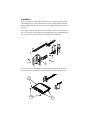
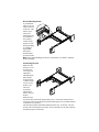
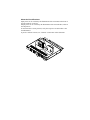
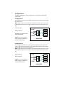
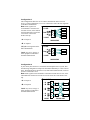
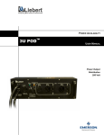
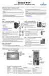
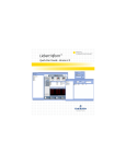
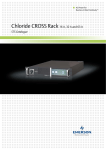
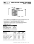
DUAL INPUT POWER DISTRIBUTION
MICRO SMARTSWITCH
USER MANUAL
200 VAC to 240 VAC
50/60 Hz
24 Amps
General Description
The Liebert Micro SmartSwitch (MSS) is a single Phase Dual Input rack mountable Power Distribution Unit (PDU) with a built in Automatic Transfer Switch.
When Input A falls below 168 VAC and Input B is valid, the output is automatically transferred to Input B. The output is transferred back to Input A when Input
A is valid and rises above 178 VAC. This high speed transfer rate ensures that
the transfer is transparent to the sensitive equipment.
The two sources are not required to be in phase. This is an effective solution that
builds in redundancy and increases the AC power availability of connected
equipment. If the dual input power is fed through two independent AC sources,
then the system availability is increased and the dual input advantages are fully
used.
The Micro SmartSwitch provides 12 receptacles that distribute redundant AC
power and may be rack mounted. There are four groups of three IEC-320 (10A)
receptacles, where each group is backed up by a 10A magnetic circuit breaker.
The MSS has two attached line cords that are terminated with NEMA L6-30
plugs with a 20A fuse for each. The total load for the MSS cannot exceed 24A of
AC load at 200-240 VAC. Also the load for each of the four groups cannot
exceed 10A or the internal breaker may trip or the fuse will blow. The load must
be balanced among the four segments such that the total current draw per section
does not exceed 10A and a total of 24A for all the four segments of the MSS.
This product provides line-to-line surge protection of 500 Joules.
Glossary of Symbols
Risk of Electrical Shock
!
Indicates Caution - followed by important instructions
Bonded to Ground
AC Voltage
I
O
On
Off
No user servicable parts inside
About This Device
This guide serves as an outline to assist Qualified personnel with the installation
of the Liebert Micro SmartSwitch. The input voltage for this Micro SmartSwitch
unit is 200VAC to 240VAC.
This Micro SmartSwitch includes the following features:
• Mounts in 1U of rack space
• Provides 12 receptacles on 4 circuit breakers
• Protects against electrical line surges and spikes
This Micro SmartSwitch is UL and c-UL listed as Information Technology
Equipment.
!
WARNING: There is a risk of personal injury from electrical shock
and hazardous energy levels. The installation of options and routine
maintenance and service of the product must be performed by individuals
who are knowledgeable about the procedures, precautions, and hazards
associated with AC power products (trained service technician).
To reduce the risk of electrical shock and/or equipment damage when installing
or servicing the Micro SmartSwitch:
• The Micro SmartSwitch must be disconnected from the product and
unplugged from the AC electrical outlet before servicing or repairing product.
• Do not overload the output of the Micro SmartSwitch. The total connected
load should not exceed rated input power.
• Do not exceed the leakage current limit for the Micro SmartSwitch in your
system. See the “Earth Leakage Current” section later in this document for
limits.
Earth Leakage Current
To reduce the risk of electrical shock due to high leakage current, a reliable
grounded (earth) connection is essential before connecting Micro SmartSwitch to
AC power. Observe the following limits when connecting the product to AC
power distribution devices.
For products that have attached AC power cords directly connected to the building power, the total combined leakage current should not exceed 5 percent of the
rated input current for the device.
For products that have detachable AC power cords, the total combined leakage
current should not exceed 3.5mA.
Voltage Selection
On connected equipment that have voltage select switches, make sure that the
switch is set for the type of voltage you use (208/240 VAC).
IMPORTANT SAFETY INSTRUCTIONS
SAVE THESE INSTRUCTIONS.
This manual contains important instructions that should be closely followed during installation and maintenance of this product.
This product is designed for Commercial/Industrial use only. It is not intended
for use with life support and other U. S. FDA designated “critical” devices. Maximum load must not exceed that shown on the rating label. See Limited Warranty.
WARNING: Lethal voltages may be present within this unit even when it is
apparently not operating. Observe all cautions and warnings in this manual.
Failure to do so MAY result in serious injury.
This equipment or Micro SmartSwitch is designed for use on a properly
grounded (earthed), 208/240 VAC, 50Hz or 60Hz supply.
ELECTROMAGNETIC COMPATIBILITY- The Micro SmartSwitch complies
with the limits for a CLASS B digital device, pursuant to part 15 of FCC rules.
These limits provide reasonable protection against harmful interference. If this
device is not installed and used in accordance with the instruction manual, it may
cause harmful interference to radio communications. Not operating this device in
accordance with these instructions may cause harmful interference, which the
user must correct at their own expense.
Operate the Micro SmartSwitch in an indoor environment only in an ambient
temperature range of 0°C to 50°C (32°F to +122°F). Install it in a clean environment, free from conductive contaminates, moisture, flammable liquids, gasses, or
corrosive substances.
Turn the Micro SmartSwitch off and isolate it from other equipment before
cleaning. Use a soft cloth, never liquid or aerosol cleaners.
Keep the vents free from dust accumulation that could restrict airflow.
Never block or insert any object into the ventilation holes or other openings.
Installation
Place rear rail [R] over the studs in the front rail [F]. Tighten nuts finger tight.
The mounting tab [T] will be facing out, so the holes align with the rack sides.
Adjust length of rail assembly to fit inside rack. Tighten either the wing nuts or
hex nuts.
Insert cage nut (one on each side) in rack. Set hooks at rear of rail over holes in
rack. Use screw [2] (one on each side) to attach rails to rear of rack through cage
nut. Use screw [2] (two on each side) to attach rails to front of rack.
R
F
T
OUTSIDE
FRONT
2
Use screws [1] (two on each side) to attach brackets to side of unit. Slide unit
into rails and secure by using screws [2] (one on each side) to attach the unit.
1
2
1
Ground Bonding Screw
A ground bonding screw is provided on the rear
of the unit. This
feature is provided as an
attachment point
for conductors
the rack may
contain for the
purpose of functional grounding
or bonding of
ungrounded
metal parts.
Ground cables
are not included.
Note: The Ground Bonding wire must be a minimum of 10 AWG to maintain
proper grounding.
Connecting Devices
Make sure that
the devices connected do not
exceed the unit
capabilities.
This Dual Input
Micro SmartSwitch features
3 output receptacles per circuit
breaker, for a
total of 12
receptacles.
This model is
rated at 10A per
breaker.
Each block of 3
receptacles has a maximum output rating of 10A. If the total connected load
exceeds 10A, the circuit breaker will trip and interrupt power to all loads attached
to that block of receptacles.
The maximum output of this Micro SmartSwitch is 24A. If the total load connected to all load segments exceed 24A, the circuit breaker at the wall could trip
and interrupt power to all loads.
About the Circuit Breakers
Input power can be verified by the illumination of the two LEDs on the front of
the unit, marked ~A and ~B.
Output power can be verified by the illumination of the circuit breaker, when in
the On position
If connected device is not powered, verify the respective circuit breaker is On
and illuminated.
If power is still not restored, see “Contacts” section later in this document.
Configurations
The Micro SmartSwitch can be configured to fit several power distribution
requirements.
Configuration 1
This application shows use of the Micro SmartSwitch in conjunction with singleline cord devices .
Note: Each segment can accommodate a maximum current draw of 10A, so the
individual load connected to it must not exceed 10A or the circuit breaker will
trip.
~A: AC Input A
~B: AC Input B
1,2,3,4: Load segments on the
Micro SmartSwitch
L6-30P
Load
1
~A
P
Dual Input D 2
3
~B
U
4
L6-30P
Load: Any server, storage, or
other equipment connected to
the Micro SmartSwitch
Load
Load
Load
200-240 VAC
Configuration 2
This configuration shows the use of the Micro SmartSwitch with 3-line cord
devices. The figure below shows how three Micro SmartSwitchs can be used to
connect with up to four 3-line cord devices.
Note: Each segment can accommodate a maximum current draw of 10A, so the
individual load connected to it must not exceed 10A or the circuit breaker will
trip.
~A: AC Input A
~B: AC Input B
Load: Any server, storage, or
other equipment connected to
the Micro SmartSwitch
L6-30P
Load
1
~A
P
Dual Input D 2
3
~B
U
4
L6-30P
200-240 VAC
Load
Load
Load
Configuration 3
This configuration shows the use of a Micro SmartSwitch with 2-line cord
devices. In this configuration, a server is connected to each of the four segments
of the Micro SmartSwitch.
Note: Each segment can
L6-30P
Load
accommodate a maximum current draw of 10A, so the individ1
~A
P
Load
ual load connected to it must not
Dual Input D 2
3
exceed 10A or the circuit
Load
~B
U
4
breaker will trip.
Load
L6-30P
~A: AC Input A
200-240 VAC
~B: AC Input B
1,2,3,4: Load segments on the
Micro SmartSwitch
Load: Any server, storage, or
other equipment connected to
the Micro SmartSwitch
L6-30P
1
~A
P
Dual Input D 2
3
~B
U
4
L6-30P
Load
Load
200-240 VAC
Configuration 4
If your facility does not have a centralized Uninterruptible Power System, then
the following configuration will provide maximum redundancy in a rack environment. The diagram below shows how to use three Micro SmartSwitchs, each connected to a UPS and a server.
Note: Each segment can accommodate a maximum current draw of 10A, so the
individual load connected to it must not exceed 10A or the circuit breaker will
trip.
DUAL INPUT
~A: AC Input A
P
~A
Load
D
UPS
~B
~B: AC Input B
U
P
~A
Load: Any server, storage, or
Load
D
UPS
~B
other equipment connected to
U
the Micro SmartSwitch
P
~A
Load
D
UPS
~B
U
L6-30P
200-240 VAC
Liebert Micro SmartSwitch Specifications
Liebert Model Name
Micro SmartSwitch
Part Number
MSS30A-240
Unit Dimensions (H x W x D) in
1.72 x 17.00 x 15.25 in
(mm)
(43.7mm x 432mm x 387mm)
Unit Weight: lbs.(kg)
20.0 lbs.(9.7kg)
Shipping Weight: lbs.(kg)
32.0 lbs.(14.55kg)
LED Indictors
Input A (Primary) / Input B (Secondary)
Nominal Input Voltage Range
200 – 240VAC
On-Line Voltage Range
180 – 262VAC
Input Plug
(2) Attached x L6-30 Plugs
Input Frequency
50/60Hz
Input Surge Rating
500J
Output Connectors
(12) x IEC-320-C13
Output Circuit Breaker Protection Rating
(4) x 10A
Output Power (VA) Rating
4320
Maximum Output Current
24A
Transfer Time
<18ms
Environmental
Operating Temperature
0°C to 50°C (32°F to 122°F)
Storage Temperature
-30°C to 60°C (-22°F to 140°F)
Relative Humidity
10 % to 80 %, non-condensing
Operating Altitude
0 to 10,000 feet above sea level
Safety and Agency
Safety Markings
UL, c-UL
Safety Certifications
UL1950
EMC Markings
FCC
Emissions
FCC Class A,
Immunity
ANSI C62.41 Cat B (formerly IEEE 587)
DUAL INPUT POWER DISTRIBUTION
Micro Smart Switch
USER MANUAL
The Company Behind the Products
Technical Support
With over a million installations around the globe,
Liebert is the world leader in computer protection
systems. Since its founding in 1965, Liebert has
developed a complete range of support and
protection systems for sensitive electronics:
United States
1050 Dearborn Drive
P.O. Box 29186
Columbus, OH 43229
1-800-222-5877
Outside the United States
+614-888-0246
•
•
•
•
•
Environmental systems—close-control air
conditioning from 1 to 60 tons
Power conditioning and UPS with power
ranges from 300 VA to more than 1000 kVA
Integrated systems that provide both
environmental and power protection in a
single, flexible package
Monitoring and control—from systems of any
size or location, on-site or remote
Service and support through more than 100
service centers around the world and a 24/7
Customer Response Center
While every precaution has been taken to ensure
the accuracy and completeness of this literature,
Liebert Corporation assumes no responsibility and
disclaims all liability for damages resulting from
use of this information or for any errors or
omissions.
© 2001 Liebert Corporation
All rights reserved throughout the world.
Specifications subject to change without notice.
® Liebert and the Liebert logo are registered
trademarks of Liebert Corporation. All names
referred to are trademarks or registered
trademarks of their respective owners.
SL-20350 (10/01)
24 hours a day, 7 days a week
1-800-222-5877
3-Phase UPS
1-800-543-2778
Environmental Control
1-800-543-2778
Italy
Via Leonardo Da Vinci 8
Zona Industriale Tognana
35028 Piove Di Sacco (PD)
+39 049 9719 111
FAX: +39 049 5841 257
Asia
23F, Allied Kajima Bldg.
138 Gloucester Road
Wanchai
Hong Kong
+852 2 572 2201
FAX: +852 2 831 0114
Web Site
www.liebert.com