1
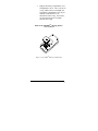
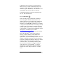
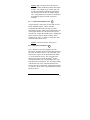
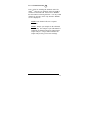
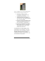
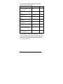
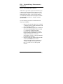
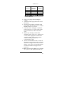
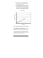
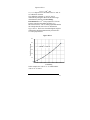
TD-500D™
Handheld Oil-in-Water Meter
User’s Manual
Revision: C
P/N 100668
2023 N. Gateway, Ste. 101, Fresno, CA 93727
United States of America
Phone: 559 253-1414 Fax: 559 253-1090
www.oilinwatermonitors.com
E-Mail: [email protected]
[email protected]
Table of Contents
PART-I
I.1 Introduction
I.1.1 Description............................................ 5
I.1.2 Getting Started....................................... 6
I.2 Operation ....................................................... 8
I.2.1 Principle of Operation............................ 8
I.2.2 Channel Selection Guidelines................. 9
I.2.3 Cuvette Selection Guidelines ............... 10
I.2.4 TD-500D™ Keypad ............................ 11
I.2.5 Instrument Power-up ........................... 11
I.2.6 Calibration........................................... 12
I.2.7 Calibration Standard Value .................. 13
I.2.8 Diagnostic Information ........................ 13
I.2.9 Channel Selection................................ 14
I.3 General Considerations for Analysis........... 15
I.3.1 Sample Analysis .................................. 15
I.3.2 General Information and Precautions ... 15
I.3.3 Linear Range ....................................... 16
I.3.4 Sensitivity ........................................... 17
I.3.5 Temperature Considerations................. 18
I.3.6 Data Quality ........................................ 18
I.4 Troubleshooting ........................................... 19
I.5 Warranty...................................................... 21
I.5.1 Terms.................................................. 21
I.5.2 Service During and After Warranty
Period.................................................. 21
I.6 Appendix A: Instrument Specifications...... 24
TD-500DTM User’s Manual—PART I
2
PART-II
II.1 fastHEX Method Introduction...................... 26
II.2 fastHEX Method: Analysis Procedure for
Lighter than Water Extraction Solvents ...... 28
II.3 Analysis Procedure for Heavier than Water
Extraction Solvents ....................................... 31
II.4 Calibration Procedure for the TD-500D™... 34
II.4.1 Option 1: Calibrating with Standard
Solutions............................................. 34
II.4.2 Option 2: Calibrating by Correlation
to an External Method (i.e. US EPA
1664) or other standard oil and grease
method............................................... 37
II.5 Using the TD-500D™ Oil-in-water Meter
CheckPOINT™ Solid Reference Standard ......... 40
II.6 Extraction and Calibration Procedure
Method Supplies .................................................. 42
TD-500DTM User’s Manual—PART I
3
PART-III
III.1. No-Solvent Method for Oil-in-Water
Analysis with the TD-500D......................... 46
III.2 Equipment .................................................. 48
III.3 Initial Preparation ...................................... 50
III.4 Calibration: 0–100 ppm Oil-in-Water....... 51
III.5 Analysis: 0–100 ppm Oil-in-Water............ 54
III.6 Extended Range Measurements—
Channel A................................................... 57
III.7 Extended Range Measurements—
Channel B ................................................... 64
III.8 Equipment Clean-up and Re-use ............... 65
TD-500DTM User’s Manual—PART I
4
PART-I
I.1
Introduction
I.1.1 Description
The TD-500DTM is a dual-channel, handheld
fluorometer designed for quick, easy and reliable
measurements of crude oil, fuel oil, lube oil, diesel,
some gas condensates and refined hydrocarbons in
water or soil. When properly calibrated with a
correlation method or a known standard, the TD500DTM can be used to measure the hydrocarbon
concentrations of water samples in less than 4 minutes.
The TD-500DTM is not designed to measure gasoline,
BTEX, aromatic solvents, or BTEX-component gas
condensate in water or soil. Contact us about the TD3100TM bench top oil-in-water analyzer for
measurement of gasoline, phenol, BTEX, or aromatic
chemicals in water. Please contact
[email protected] for more information.
The dual-channel design makes the TD-500DTM
applicable to a wide range of hydrocarbon types and
concentration ranges. Channel A provides the extreme
sensitivity required to monitor very low hydrocarbon
concentrations and for detecting weakly fluorescent
hydrocarbons such as some gas condensates, diesel
fuel and refined petroleum products. Channel B was
designed for those applications where a wide
concentration range is more important than high
sensitivity. Channel B is ideal for the analysis of
produced water samples where crude oil
concentrations can vary from low levels to over one
thousand parts-per-million.
TD-500DTM User’s Manual—PART I
5
The TD-500DTM is normally used with a solventextraction method such as the Oil-in-water Analysis
Procedure described in Part II of this manual. In this
method, the target hydrocarbon is extracted into a
suitable solvent. The TD-500DTM measures the
hydrocarbon content of the extract, and calculates the
hydrocarbon content in water.
NOTE: The TD-500DTM is not explosion-proof
or intrinsically safe. It is not designed in any way
to be used in an explosion-proof designated area.
I.1.2 Getting Started
I.1.2.1 Incoming Inspection
Upon receiving your instrument, please inspect
everything carefully and make sure all ordered
accessories are present. All shipments include:
•
•
•
•
TD-500DTM Handheld Oil-in-Water Meter
4 AAA Batteries
User’s Manual
Recommended Accessories (as ordered):
o Carrying Case
o CheckPOINTTM Solid Standard
o Appropriate cuvettes and adapters.
I.1.2.2 Battery Installation
1.
2.
The battery compartment is located at the
back of the instrument. Loosen the screw
and remove the battery compartment
cover (See Figure 1).
Install the 4 AAA batteries. Orient the
batteries as indicated by the diagrams
inside the battery compartment.
TD-500DTM User’s Manual—PART I
6
3.
Replace the battery compartment cover
and tighten the screw. The cover has an
o-ring, which creates a watertight seal.
The battery compartment cover may be
difficult to install if there is no
lubrication on the o-ring. If necessary,
use silicon-based grease to lightly
lubricate the o-ring.
Back of the TD-500DTM showing battery
cover removed
Figure 1. TD-500DTM Battery Compartment
TD-500DTM User’s Manual—PART I
7
I.2
Operation
I.2.1 Principle of Operation
The TD-500DTM responds to the fluorescent aromatic
compounds in the target hydrocarbon. The instrument
must be calibrated by measuring the intensity of
fluorescent light that is generated by a know
concentration of hydrocarbon. Once calibrated, the
instrument converts the fluorescent light intensity from
an unknown sample into units of concentration.
Figure 2 shows the general relationship between
fluorescence intensity and concentration.
C
∞
IF
Fluorescence (IF)
Linear Range
Limit
Concentration Quenching
-orInner Filter Effect
Concentration (C)
Detection
Limit
Figure 2. Fluorescence vs. Concentration
Every hydrocarbon will have a detection limit and a
linearity limit. The detection limit is the lowest
concentration that the instrument can detect. The
linearity limit varies with each type of hydrocarbon.
The linear range is defined by the concentration span
from the detection limit to the linearity limit. As
concentration increases beyond the linearity limit, the
TD-500DTM User’s Manual—PART I
8
slope of the line begins to reduce. At very high
concentrations, the slope may become negative. For
most crude oils the linearity limit is well beyond 1000
ppm.
The TD-500DTM must be operating in the linear range
to display accurate results. The linear range can be
optimized for any monitoring application by selecting
the best combination of measurement channel (A or B)
and cuvette size (mini-cell or 8 mm cuvette). See
Section I.3 for configuration guidelines.
After calibration you must perform a simple test to
determine if your calibration standard is in the linear
range. First select a channel and proper cuvette size
and calibrate the TD-500DTM with a standard solution
of known concentration. Then prepare a new standard
that is half the concentration of the standard solution
by mixing equal volumes of the original calibration
standard and pure blank. Place the diluted standard in
a sample cell, place the cell in the TD-500DTM and
press <READ>. If the displayed result is greater than
half the original standard concentration, allowing for
some error due to dilution, the TD-500DTM calibration
is beyond the linear range. The linear range is
dependent upon the sample cuvette size and the optical
channel of the TD-500DTM; thus using a smaller
cuvette size and/or changing the optical channel can
extend the linear range.
I.2.2 Channel Selection Guidelines:
Channel A is generally used where high sensitivity is
required. Channel A is ideal for weakly fluorescent
hydrocarbons or for very low concentrations of
hydrocarbons. Channel B is used whenever Channel A
gives poor linearity over the concentration range of
interest or if channel A is over range for the calibration
standard. Proper channel selection depends on the
TD-500DTM User’s Manual—PART I
9
type of hydrocarbon and the desired concentration
range. The proper channel is determined when the
calibration on the particular channel and using a
particular cuvette size produces a diagnostic reading of
%FS-Std > 2, but less than 100, while at the same time
maintaining linearity over the measurement range. See
Sections I.3.3 and I.3.4 for further details.
Channel A:
In most cases, use channel A for measuring
following hydrocarbons in water or soil:
Gas Condensate
Diesel
Marine Diesel
Fuel Oil #6 (< 1 ppm)
Lube Oil
Crude Oil in Produced Water (< 5 ppm)
Channel B:
In most cases, use channel B for measuring:
Crude Oil in Produced Water (0 > 100 ppm)
Heavy crude oils (higher concentrations)
Heavy fuel oils (higher concentrations)
I.2.3 Cuvette Selection Guidelines:
Use the smaller mini-cell cuvettes (P/N 50952) for
measuring heavy crude oil and other highly fluorescent
oils in water. Use the larger 8 mm diameter cuvettes
(P/N 50957) for diesel, gas condensates, lube oil and
other refined hydrocarbons in water or for very low
concentrations of crude oil-in-water. The cuvette size
is determined when the calibration on the particular
channel size produces a diagnostic reading of %FS-Std
> 2, but less than 100, while at the same time
TD-500DTM User’s Manual—PART I
10
maintaining linearity over the desired measurement
range. See Sections I.3.3 and I.3.4 for further details.
I.2.4 TD-500D™ Keypad
Make a
measurement
Exit, return to
Home screen
Power ON/OFF
Channel select
Enter concentration of
calibration standard
Advance to
next screen
Calibrate
Diagnostic
Screen
I.2.5 Instrument Power-up
ON/
OFF
Turn the instrument face-up and press the <ON/OFF>
button. The instrument should turn on and display an
introduction screen with a count-down indicator in the
lower right corner:
T DH I T D - 5 0 0 D
T DH I 1 B 0 8 0 5
5
Count-down Timer
After 5 seconds, when the count-down indicator
reaches zero, the TD-500DTM displays the “Home”
screen and is ready for use:
RE A DY
A
Channel Indicator (A or B)
The channel indicator will display the channel that was
active during the instrument’s previous use.
TD-500DTM User’s Manual—PART I
11
If the display does not activate, check the batteries.
Make sure they are fresh and installed in the proper
orientation. If the display shows meaningless
characters, replace the batteries. The TD-500DTM will
automatically turn off if it is idle for 3 minutes.
Fresh alkaline batteries will provide adequate power
for over 1000 measurements.
I.2.6 Calibration
CAL
There are many ways to calibrate the TD-500DTM.
The most popular calibration method in the USA
offshore industry is by correlation to the standard US
EPA method. For details about this method and
alternatives see Section II.4. Another way to calibrate
is using a known standard made from the target oil and
a blank solvent. This method is generally used in the
field for quick analysis or when an official laboratory
is not available. For a discussion regarding the various
philosophies of calibration please contact
[email protected] or visit our web site.
Before the TD-500DTM can be used to analyze a
sample, you must calibrate it with a blank and a
calibration standard containing your target
hydrocarbon. If you are following a solvent-extraction
method, use the pure extraction solvent for the blank.
Prepare the calibration standard by dissolving a known
amount of hydrocarbon in a known volume of
extraction solvent. The standard solution will then
have a known concentration. This is the standard
value (STD VAL). The TD-500DTM can also be
calibrated by correlating the instrument readings to
another oil-in-water analysis method i.e. US EPA
1664.
TD-500DTM User’s Manual—PART I
12
NOTE: Make sure that you use the same size
cuvette for blank, calibration solution and sample
analysis. For example, if you use the mini-cell
cuvettes for blank and calibration solution then
use must mini-cell cuvettes for sample analysis
also. Using different size cuvettes for calibration
and sample analysis will result in incorrect
readings.
I.2.7 Calibration Standard Value
STD
VAL
Assign a numeric value between 1 and 9999 for your
known standard solution. This is done after
performing the calibration as the last step of the
calibration procedure. Make sure the instrument is set
to the proper channel (A or B), then use the up and
down arrows to adjust the standard value. Holding this
button down will activate faster scrolling. When
finished, press <ESC> or <ENT> to accept the value
and return to the Home screen.
NOTE: No units are shown on the screen.
I.2.8 Diagnostic Information
DIAG
Press <DIAG> to access the diagnostic screens.
Record the %FS-BLK and %FS-STD values shown on
the screen for future reference. The %FS-BLK is the
fluorescence response of the TD-500D for the blank
i.e. clean extraction solvent. The %FS-STD is the
fluorescence response of the TD-500DTM for the
calibration standard. For best performance the %FSSTD should be greater than 2. The %FS-STD reading
is the fluorescence value of the standard above the
fluorescence value of the blank. The maximum values
are 100 %FS. Press <ESC> when finished to return to
the Home screen.
TD-500DTM User’s Manual—PART I
13
I.2.9 Channel Selection
A/B
Press <A/B> for switching the channels on the TD500DTM. There are two channels on the TD-500D™,
Channel A and Channel B. Please refer to Section
I.2.2 for channel selection guidelines. You may switch
channels by pressing <A/B> only when the “HOME”
screen is displayed.
NOTE: Each channel will store a separate
calibration.
NOTE: Analyze your samples on the calibrated
channel only. For example if your TD-500D™ is
calibrated on Channel B, then use Channel B for
sample analysis. Using a different channel for
sample analysis will give incorrect readings.
TD-500DTM User’s Manual—PART I
14
I.3
General Considerations for Analysis
I.3.1 Sample Analysis
1.
2.
3.
4.
5.
Turn on the instrument. Make sure the proper
channel (A or B) is displayed.
Insert your sample in a clean cuvette and put
the cuvette in the appropriate cuvette adapter.
Be sure to wipe any oil or finger prints from
the outside of the cuvette.
Insert the cuvette adapter in the TD-500DTM
adapter well and press <READ>. The
instrument will measure and average the
signal over a 5 second interval.
The result will be displayed on the screen.
The top left corner will display “WAIT” for 5
seconds. Once “WAIT” disappears, another
sample reading can be performed.
I.3.2 General Information and Precautions
•
•
•
The adapter well with the appropriate adapter
accepts either the mini-cell cuvettes or the 8
mm round cuvettes. Consult factory for
questions regarding use of various cuvettes.
Take care not to spill samples into the adapter
well. Promptly wipe any spills. Simple
alcohol rinse of the adapter well should
neutralize any potential chemical attack.
The TD-500DTM is very sensitive and even
small amounts of material from a previous
sample may result in errors. Use a clean
cuvette for each reading. Wipe the outside of
the cuvette with a Kimwipe or similar
laboratory tissue. Do not use paper towels or
kitchen wipes because the optical brighteners
in the paper may cause a false reading.
TD-500DTM User’s Manual—PART I
15
•
•
•
•
•
Fill the cuvette at least 75% full; significant
error will result if the cuvette is not properly
filled. Use a minimum of 75 µL (0.075 mL)
in a mini-cell cuvette, and a minimum of 1
mL in an 8 mm diameter cuvette for best
results.
The cuvette MUST BE CLEAN AND DRY
on the outside when taking readings. Moisture
and condensation or fingerprints on the
outside can result in error. Use laboratory
grade tissues or wipes for wiping the cuvettes.
Avoid air bubbles in the cuvette. Bubbles in
samples may cause drifting of the reading.
Slight tapping on the outside cuvette wall
should help remove any bubbles.
Avoid transferring emulsions to the cuvette
since bubbles of water in the extract will
cause incorrect measurements.
Always make sure to analyze the samples on
the calibrated channel only. Using a different
channel for sample analysis will give
incorrect readings.
I.3.3 Linear Range
The linear range is the concentration range within
which the readout of the TD-500DTM is directly
proportional to the concentration of the hydrocarbon.
You must make sure the instrument is calibrated in the
linear range (see Section I.2.1).
The linear range is dependent upon the sample cuvette
size and the optical channel of the TD-500DTM; thus
using a smaller cuvette size and/or changing the optical
channel can extend the linear range. The glass minicell cuvettes provide a smaller cell diameter than the 8
mm round cuvettes.
TD-500DTM User’s Manual—PART I
16
For heavy and highly fluorescent oils, we recommend
using the mini-cells with channel B for the widest
possible linear range.
The linear range must always be checked after the first
calibration by diluting the calibration solution half
with blank and then measuring the concentration on
the TD-500DTM. If the displayed result is greater than
half the original standard concentration, allowing for
some error due to dilution, the TD-500DTM calibration
is beyond the linear range.
I.3.4 Sensitivity
The instrument’s sensitivity is measured by the %FSSTD value on the diagnostic screen. For best results,
the %FS-STD should be greater than 2. The sensitivity
should be checked when initially calibrating the TD500DTM.
The calibration and operation guidelines mentioned in
this manual work with most oils. However, some
refined oils and condensates do not have enough
fluorescence (%FS-STD < 2). If the %FS-STD is less
than 2 or if the calibration screen says “Standard <
Blank, Recalibrate”, then follow the steps below:
1.
2.
3.
4.
5.
Make sure you are using clean solvent and
clean cuvettes.
If the TD-500DTM is set to channel B, then
switch to channel A, and/or;
Use larger cuvette, and/or;
Use higher concentration of oil in solvent for
calibrating the TD-500DTM.
If the above suggestions do not help, contact
Turner Designs Hydrocarbon Instruments’
Service Department
([email protected]).
TD-500DTM User’s Manual—PART I
17
I.3.5 Temperature Considerations
Perform all calibrations and sample analysis at ambient
temperature.
I.3.6 Data Quality
The TD-500DTM is only as accurate as the standards
that are used to calibrate it and the accuracy of the
measurement of the standards into the solvent. This is
why it is important to take care when preparing
standards, samples, and blank. One should follow good
laboratory practices when handling reagents and
preparing standard solutions. Also, follow all solvent
handling rules for the specific solvent and the specific
facility. Use safety glasses with side shields or splash
goggles while handling acids and solvents. Use nitrile
examination gloves to protect your hands. Consult
your company’s safety guidelines for detailed safety
instructions.
TD-500DTM User’s Manual—PART I
18
I.4
Troubleshooting
The following messages can appear on the TD-500DTM
display screen:
Message 1: “Low Battery”
Cure 1: Replace the batteries with 4 new AAA
batteries.
Message 2: “Circuit Failure”
Cure 2: Contact Turner Designs Hydrocarbon
Instruments, Inc. according to directions
in Section I.5.2.
Message 3: “High Blank”
Cure 3: Recalibrate the TD-500D with a clean
blank.
Message 4: “Standard too High: Recalibrate”
Cure 4: a) Use lower concentration of
Calibration solution; and/or
b) Use smaller cuvette size for blank,
calibration standard and for sample
analysis; and/or
c) Switch to channel B and recalibrate.
NOTE: The optimum combination of channel
and cuvette size will depend on the type of oil,
detection limit and measurement range.
If the above suggestions do not help, please make a
copy of the Troubleshooting Worksheet and then
complete the worksheet with the requested
information. The completed worksheet should be sent
to Turner Designs Hydrocarbon Instruments
([email protected] or fax + 1 559 2531090) or your local dealer.
TD-500DTM User’s Manual—PART I
19
TD-500D™ Troubleshooting Worksheet
Customer Name:
Company Name:
Company Address:
Country:
Phone Number:
Fax Number:
E-Mail Address:
1) API or specific gravity of oil or condensate:
2) Extraction solvent :
3) Calibration method: (Prepared solutions or
correlation)
(If correlation is used, attached correlation
data and/or graph)
4) Measurement channel used (A or B):
5) Size of cuvette used (mini-cell or 8 mm
cuvettes):
6) Calibration solution concentration:
7) Standard value (STD VAL):
8) Diagnostic screen (DIAG) readings:
%FS-Blk:
% FS-Std:
9) Linearity test –
Concentration of diluted solution
Measured concentration of diluted
solution
TD-500DTM User’s Manual—PART I
20
I.5
Warranty
I.5.1 Terms
Turner Designs Hydrocarbon Instruments warrants the
TD-500DTM Oil-in-water Meter and accessories to be
free from defects in materials and workmanship under
normal use and service for a period of one year from
the date of shipment. The instrument and accessories
must be installed, powered, and operated in
compliance with the directions in this TD-500DTM
User’s Manual and the instructions accompanying the
accessories. Additional 12 months warranty is
available at the time of order. Please consult factory.
The following items are not covered under
warranty:
•
•
•
•
Damage resulting from contact with
solvents or other corrosive liquids and
gases.
Damage resulting from contact with
corrosive materials or atmosphere.
Damage caused by modification of the
instrument.
Damage caused by improper handling
and physical abuse of the instrument.
I.5.2 Service During and After Warranty Period
To obtain service at any time, do the following:
1.
Write or call the Turner Designs Hydrocarbon
Instruments, Inc. Service Department and
describe the nature of the problem. See
contact information on page 23.
TD-500DTM User’s Manual—PART I
21
2.
Make minor adjustments or tests as suggested
by Turner Designs Hydrocarbon Instruments,
Inc. Service Department personnel.
3.
If the Service Personnel determine that the
TD-500DTM must be returned to the factory,
OBTAIN AN RMA (Return Material
Authorization) NUMBER BEFORE
SHIPPING THE INSTRUMENT TO
TURNER DESIGNS HYDROCARBON
INSTRUMENTS, Inc. You must ship all
items associated with the instrument,
including the TD-500DTM, the
appropriate adapter, the CheckPOINT™
Solid Standard and the carrying case.
After obtaining an RMA number, pack the
instrument and accessories well, insure it,
write the RMA # on the outside of the carton,
and ship it to Turner Designs Hydrocarbon
Instruments, Inc. prepaid. If the instrument
and/or the problem are determined to be
repairable under warranty, the instrument will
be repaired; however, all shipping costs are
for the customer’s account.
Out of warranty repair for the TD-500DTM is billed on
a flat rate basis regardless of the problem. Your bill
will include return shipment freight charges.
NOTE: Please do not return the instrument
without notice.
TD-500DTM User’s Manual—PART I
22
Address for Return Shipments:
Turner Designs Hydrocarbon Instruments, Inc.
Attn: RMA#____
2023 N. Gateway Blvd., Suite 101
Fresno, CA 93727
United States of America
Contact Information for Sales and Service
Main Phone Number: +1 559 253-1414
Main Fax:
+1 559 253-1090
Email (Sales issues only):
[email protected]
Email (Service issues only):
[email protected]
TD-500DTM User’s Manual—PART I
23
I.6
Appendix A: Instrument
Specifications
TD500 D Hand Held Oil-in-water Meter Data Sheet
1 Hydrocarbons in Water
2 Ambient Temperature
3 Area Classification
Min F/CMax F/C
4 Mounting
GENERAL
6 Weight
7 Enclosure Material
9 Power Supply Required
104/40
4 AAA Cells (1,000+ Samples)
10 Automatic Power Down
After 3 minutes of inactivity
11 Local Display
Yes, LCD
12 Output Signal
No
13 Warranty
1 Year Factory Parts and Labor
API Type Solvent
16 Measurement Method
17 Compatible Solvents
Technical Detail
41/5
Non-Metallic
Meets IP 67 standard;
dustproof and waterproof
8 IP Rating
15 Cuvettes
General Purpose
Hand / Table Top
1.75” x 3.5” x 7.25”
(4.45 cm x 8.9 cm x 18.4 cm)
13.9 oz (0.4 kg)
5 Dimensions
14 Principle
Crude Oil, Condensate, diesel,
lube oil, fuel oil, motor oil,
diesel range organics
UV Fluorescence
<45 Mini-cellAll
>45 8mm
All
Solvent Extraction
Hexane, Vertrel, AK-225,
Xylene, Freon, Horiba, (most
other extraction solvents,
consult factory)
18 Total Elapsed Time for Measurement Method < 4 min or owners preference
19 Accuracy
20 Repeatability
21 Linear Range
22 Sensitivity
23 Calibration
24 Response Time
25 Alarms
26 Warm Up
TD-500DTM User’s Manual—PART I
Better than 2% of Full Scale
Better than 2% of Full Scale
Up to 1000 ppm
Hydrocarbon Dependent
1 ppm
Single-point and blank
5 Seconds
Low battery, circuit failure,
High blank
5 seconds
24
TD-500D™ User’s Manual
PART-II
Oil-in-Water Analysis Procedure
TD-500DTM User’s Manual—PART II
25
II.1
fastHEXTM Method Introduction
II.1.1 Introduction
The fastHEXTM method for the TD-500DTM was
developed to provide a simple, rapid, accurate, safe
and environmentally friendly field procedure for the
analysis of oil and grease in water. The TD-500DTM
measures the oil content of a water sample by
measuring the fluorescent light emitted by oil that has
been extracted into hexane. Hexane is an inexpensive,
non-fluorescent, organic solvent that efficiently
extracts all types of crude oil, and separates out
quickly on top of the water sample.
The fastHEXTM method has been in use for several
years, and has been field-proven to give results that
correlate well to US EPA Method 1664 and other
official oil and grease methods. The entire procedure,
from taking a water sample to recording results, takes
less than 4 minutes. Because the method uses
inexpensive, disposable bottles and cuvettes, solvent
waste is reduced to a minimum. Also, unlike Freon
and other halogenated or chlorinated solvents, hexane
can be disposed of in most oil and gas facilities
without worrying about physical exposure.
II.1.2 Other Methods:
There have been many oil and grease analysis methods
developed over the years and many of them are useful.
If you have questions regarding the viability of any
method please consult our Service Department or the
appropriate department in your own company.
TD-500DTM User’s Manual—PART II
26
II.1.3 Alternative Solvents
Although the fastHEXTM method was originally
intended to use hexane, its solvent extraction and
measurement procedures can also be applied to other
lighter-than-water solvents (xylene, petroleum ether,
etc.). In addition, the procedure can be modified
allowing use of a variety of heavier-than-water
solvents (Vertrel MCA, Ashikleen AK-225,
perchloroethylene, etc.). Analysis procedures for
lighter-than-water solvents and heavier-than-water
solvents are given in Section II.2, and Section II.3,
respectively.
II.1.4 Important note regarding solvents:
Some solvents, especially Vertrel MCA, Ashikleen
AK-225 and chloroform, can damage the TD-500DTM
if left in contact with the plastic parts. If you spill
solvents on the case or inside the adapter well, flush
the contacted area immediately with isopropyl alcohol
and dry the area with a non-abrasive lab tissue.
Always follow safety rules for handling and disposing
of solvents.
TD-500DTM User’s Manual—PART II
27
II.2 fastHEX TM Method: Analysis
Procedure for Lighter than Water
Extraction Solvents
(See page 36 for Calibration Procedure)
This procedure is for use with lighter than water
extraction solvents such as:
Hexane
Cyclohexane
Heptane
Octane
Xylenes (may give high blank reading)
Toluene (may give high blank reading)
NOTE: Please use this procedure even if your solvent
is not listed above and you are using lighter than water
extraction solvent.
NOTE: If you are using heavier than water extraction
solvent then refer to Section II.3 of this manual for
heavier than water extraction solvent analysis
procedure.
II.2.1 Analysis Procedure:
1.
Collect 100 mL of contaminated water in a
clean, graduated prescription bottle or suitable
graduated glass container.
2. Add 6 N hydrochloric acid until the pH of the
water sample is < 2. Check the pH with pH
paper.
NOTE: Depending on the method philosophy of the
facility, the sample can be measured at normal pH.
3. Add 10 mL of extraction solvent and securely
cap the bottle.
TD-500DTM User’s Manual—PART II
28
4.
5.
6.
7.
8.
9.
10.
11.
12.
13.
Extract oil from the water by vigorously
shaking the bottle for 2 minutes.
Allow the extraction solvent to separate from
the water for approximately 1 minute. If the
extraction solvent is trapped in an emulsion;
break the emulsion by agitating with a clean
pipette. Allow the extract to sit for several
minutes after agitating the emulsion. This
will allow the solvent to separate from the
water. The solvent extract will be floating on
top of the water.
Carefully release the pressure from the bottle.
Fill the appropriate cuvette (mini-cell or 8
mm cuvette) ¾ full with the solvent extract.
Wipe the outside of the cuvette with a clean
laboratory grade tissue or cloth to remove any
liquid, dirt or oil that might be present.
Insert the cuvette into the TD-500DTM cuvette
holder in the adapter well and close the lid.
If the TD-500DTM is off, press the <ON/OFF>
button and allow the instrument to proceed to
the end of the countdown period.
Make sure the proper channel (A or B) is
shown in the lower left-hand corner of the
display. If it is not, press the <A/B> button
until the correct channel appears.
Press the <READ> button and then record the
reading after the “WAIT” message
disappears.
If the TD-500DTM was calibrated using a
look-up table, use the look-up table to convert
the reading to oil concentration.
Dispose of the water, extraction solvent,
cuvette and prescription bottle in a safe,
environmentally responsible manner, in
accordance with your company’s procedures.
TD-500DTM User’s Manual—PART II
29
NOTE: If the TD-500DTM Oil-in-Water Meter reads
“OVER”, or the sample reads higher than the
correlation chart or look-up table, this means the oil
and grease concentration is too high. Follow
the steps below to overcome this issue:
1.
2.
3.
4.
Dilute the solvent extract 5 times by
combining 1 mL of solvent extract with 4 mL
of clean solvent and mix the diluted extract.
Measure the diluted extract (Steps 7 through
11 on page 29).
Record the concentration of the diluted
sample extract using the correlation chart
(Step 11 on page 29).
Multiply the result from Step 3 by five (5) to
calculate the true oil and grease result in the
water sample.
TD-500DTM User’s Manual—PART II
30
II.3 Analysis Procedure for Heavier
than Water Extraction Solvents
(See page 36 for Calibration Procedure)
This procedure is for use with heavier than water
extraction solvents such as:
Vertrel MCA
Freon
Ashikleen AK-225
Chloroform
Carbon Tetrachloride
Horiba S-316
Methylene Chloride
NOTE: Please use this procedure even if your solvent
is not listed above and you are using heavier than
water extraction solvent.
NOTE: If you are using lighter than water extraction
solvent then refer to Section II.2 of this manual for
lighter than water extraction solvent analysis
procedure.
II.3.1 Analysis Procedure:
1.
2.
3.
4.
Collect 100 mL of produced water in a clean,
graduated prescription bottle.
Add 6 N hydrochloric acid until the pH of the
water sample is < 2. Check the pH with pH
paper.
Add 10 mL of extraction solvent and securely
cap the prescription bottle with a clean,
Teflon-lined septum cap.
Extract oil from the water by vigorously
shaking the prescription bottle for 2 minutes.
TD-500DTM User’s Manual—PART II
31
5.
6.
7.
8.
9.
10.
11.
12.
13.
14.
Allow the extraction solvent to separate from
the water for approximately 1 minute. If the
extraction solvent is trapped in an emulsion;
break the emulsion by agitating with a clean
pipette. Allow the extract to sit for several
minutes after agitating the emulsion. This
will allow the solvent to separate from the
water. The solvent extract will be on the
bottom of the bottle, underneath the water.
Place a blunt needle on the end of a 3 mL
plastic syringe. Push the syringe plunger all
the way in.
Turn the prescription bottle upside down and
allow the solvent extract to settle on top of the
Teflon-lined septum cap.
While holding the prescription bottle upside
down, insert the needle through the Teflonlined septum cap far enough for the end of the
needle to be in the solvent extract.
By pulling the syringe plunger out, withdraw
1-1.5 mL of solvent extract.
Inject the solvent extract into the cuvette
(mini-cell or 8 mm cuvette, the same type
used for calibration) until the cuvette is ¾
full.
Wipe the outside of the cuvette with a clean
tissue or cloth to remove any liquid, dirt or oil
that might be present.
Insert the cuvette into the TD-500DTM adapter
well and close the lid.
If the TD-500DTM is off, press the <ON/OFF>
button and allow the instrument to proceed to
the end of the countdown period.
Make sure the proper channel (A or B) is
shown in the lower left-hand corner of the
display. If it is not, press the <A/B> button
until the correct channel appears.
TD-500DTM User’s Manual—PART II
32
15. Press the <READ> button and then record the
reading after the “WAIT” message
disappears.
16. If the TD-500DTM was calibrated using a
loop-up table, use the loop-up table to convert
the reading to oil concentration.
17. Dispose of the water, extraction solvent,
cuvette and prescription bottle in a safe,
environmentally responsible manner, in
accordance with your company’s procedures.
NOTE: If the TD-500DTM Oil-in-Water Meter reads
“OVER”, or the sample reads higher than the
correlation chart or look-up table, this means the oil
and grease concentration is too concentrated.
The following steps should be performed to dilute the
sample extract:
1.
2.
3.
4.
Dilute the solvent extract 5 times by
combining 1 mL of solvent extract with 4 mL
of clean extraction solvent and mix the
diluted sample extract.
Measure the diluted sample extract using the
TD-500DTM Oil-in-Water Meter (Steps 10
through 15 on page 32-33).
Record the concentration of the diluted
sample extract using the correlation chart
(Step 16 on page 33).
Multiply the result from Step 3 by five (5) to
calculate the true oil and grease result in the
water sample.
TD-500DTM User’s Manual—PART II
33
II.4 Calibration Procedure for the TD500D™
(For all extraction solvents)
II.4.1 Option 1: Calibrating with Standard
Solutions
The TD-500DTM Oil-in-water Meter can be calibrated
with a standard solution of oil in extraction solvent.
The standard solution (known oil concentration) is
prepared by dissolving a known amount of oil in a
known volume of extraction solvent. The instrument
is calibrated by relating measured fluorescence
response to the concentration of oil in the standard.
II.4.1.1 Calibration Standards
Sample preparation for the TD-500DTM Oil-in-water
Analysis Methods involves extracting the oil from a
100 mL water sample into 10 mL of solvent.
Therefore, the oil concentration in the extraction
solvent will always be 10 times greater than the oil
concentration of the water sample. For example, a 100
ppm oil concentration in a water sample will give a
1000 ppm oil concentration in the solvent extract. This
10 times concentration factor is affected during
calibration i.e. if you want to calibrate the TD-500DTM
for 100 ppm oil in water, you would use a standard
solution of 1000 ppm in the exaction solvent.
II.4.1.2 Calibration Standard Preparation
Part 1—Prepare a 10,000 ppm Stock Standard.
1.
Pipette 1 mL (1000 µL) of oil into a
100 mL volumetric flask that is
approximately half full of clean
extraction solvent.
TD-500DTM User’s Manual—PART II
34
2.
Cap the flask and shake it to dissolve
the oil.
Fill the 100 mL volumetric flask to the
mark with clean extraction solvent.
Cap and shake the flask to mix.
3.
4.
Part 2—Prepare a Calibration Standard
Select a concentration that is equal to the
maximum anticipated in your water samples.
Prepare a Calibration Standard by diluting the
Stock Standard with clean solvent. Recipes for
preparing several typical concentrations are given
in Table 1. To prepare the Calibration Standard
shown in column 1, pipette the Stock Standard
volume given in column 3 into a 100 mL
volumetric flask, then fill the flask to the 100 mL
mark with clean solvent.
Calibration
Standard, ppm
5,000
2,500
1,000
500
250
100
Oil-in-water
Equiv., ppm
500
250
100
50
25
10
Stock Standard
Volume
50 mL
25 mL
10 mL
5.0 mL
2.5 mL
1.0 mL
Table 1. Calibration Standards
II.4.1.3 Calibrate the TD-500D™ Oil-in-Water
Meter
1.
Before calibration begins, you must select a
TD-500DTM channel (A or B) and a cuvette
size (mini-cell cuvette or 8 mm cuvette). See
Section I.2.2 for channel selection guidelines.
TD-500DTM User’s Manual—PART II
35
2.
3.
4.
5.
6.
7.
8.
9.
10.
11.
12.
13.
14.
See Section I.2.3 for cuvette selection
guidelines.
Prepare a Blank by filling a cuvette with clean
extraction solvent. Wipe the outside of the
cuvette with a clean laboratory grade tissue to
remove any liquid, dirt or oil that might be
present.
Insert the Blank cuvette into the TD-500DTM
adapter well and close the lid.
If the TD-500DTM is off, press the <ON/OFF>
button and allow the instrument to proceed to
the end of the countdown period.
Make sure the proper channel (A or B) is
shown in the lower left-hand corner of the
display. If it is not, press the <A/B> button
until the correct channel appears.
Press the <CAL> button and then press
<ENT>.
Press <ENT> to read the response of the
Blank.
Fill a new cuvette with the Calibration
Standard. Wipe the outside of the cuvette
with a clean laboratory grade tissue to remove
any liquid, dirt or oil that might be present.
Insert the Calibration Standard cuvette into
the TD-500DTM adapter well and close the lid.
Press <ENT> to read the response of the
Calibration Standard.
Press <ENT> within 10 seconds to store the
calibration.
Press the <STD VAL> button.
Enter the STD VAL as 1/10 of the
concentration of the Calibration Standard.
Adjust the Calibration Value using the <▲>
and <▼> buttons. Press either button once
for each increment of STD VAL. Holding
either of these buttons down will activate
faster scrolling to the desired value.
Press <ENT> to accept the STD VAL.
TD-500DTM User’s Manual—PART II
36
The calibration is now complete. The calibration will
be stored and maintained when the instrument is turned
off.
II.4.1.4 Notes on error conditions and remedial
procedures
The following messages can appear on the TD500DTM display screen while calibrating the TD500DTM:
Message 1: “High Blank”
Cure 1: Recalibrate the TD-500DTM with a clean
blank.
Message 2: “Standard too High: Recalibrate”
Cure 2: a) Use lower concentration of
calibration solution; and/or
b) Use smaller cuvette size for blank,
calibration standard and for sample
analysis; and/or
c) Switch to channel B
II.4.2 Option 2: Calibrating by Correlation to an
External Method (i.e. US EPA 1664) or other
standard oil and grease method
The TD-500DTM Oil-in-water Meter can be calibrated
to give oil concentrations equivalent to an external
analysis method. This method has been used
extensively for offshore platforms in the Gulf of
Mexico to give results equivalent to EPA Method
1664. The method is based on establishing a
correlation between the TD-500DTM response of the
extracted sample and the oil concentration determined
TD-500DTM User’s Manual—PART II
37
by the external method performed at an appropriate
analysis laboratory.
Procedures for performing this type of calibration
depend strongly on the type of oil, the desired analysis
range and the nature of the external method. Please
consult the factory for additional information and
guidance.
TD-500DTM User’s Manual—PART II
38
II.5 Using the TD-500DTM Oil-in-water
Meter CheckPOINT™ Solid Reference
Standard
The CheckPOINT™ Solid Reference Standard is used
to verify the TD-500DTM Oil-in-water Meter
calibration and performance prior to sample analysis
procedure. The CheckPOINT™ Solid Standard
contains a fiber that produces an adjustable signal that
can be set to be equal to the calibration solution. The
fiber is covered by an attenuation screw. Opening the
attenuation screw (counter-clockwise rotation) will
increase the exposure of the fiber and hence will
increase the reading on the TD-500DTM. Closing the
attenuation screw (clockwise rotation) will decrease
the readings on the TD-500DTM.
The following procedure describes how a calibration
value is assigned to the CheckPOINT™ Solid
Standard. Once the CheckPOINT™ Solid Standard
has a calibration value assigned to it, the TD-500DTM
Oil-in-water Meter can be recalibrated in the field as
necessary. The CheckPOINT™ Solid Standard is also
used to verify instrument performance or calibration
stability.
II.5.1 Adjusting the CheckPOINT™ Solid
Standard
1.
2.
3.
Calibrate the TD-500DTM Oil-in-water Meter
by Option 1 (Page 36) or by Option 2 (Page
40) mentioned in this manual.
Remove the cuvette and cuvette adapter.
Remove the CheckPOINTTM Solid Standard
from its storage box. Using the 0.050” Allen
wrench provided, loosen the locking setscrew
on the back of the solid standard by turning it
counterclockwise one turn.
TD-500DTM User’s Manual—PART II
39
Picture 1. Loosening the locking setscrew on the backside of
the adjustable CheckPOINT™ Solid Reference Standard.
4.
Insert the CheckPOINT™ Solid Standard
with the “dog-ear” handle positioned closest
to the back of the adapter well.
Picture 2. Placing the adjustable CheckPOINT™ Solid
Reference Standard in the TD-500DTM.
5.
6.
7.
If the TD-500DTM Oil-in-water Meter is off,
press the <ON/OFF> button and allow the
instrument to proceed through the countdown
period.
Press the <READ> button and then record the
reading after the “WAIT” message
disappears.
Open the lid and use the 3/32” Allen wrench
provided to adjust the attenuation screw
through the hole at the top of the solid
standard to increase or decrease the value
displayed on the screen. Turning the screw
counter-clockwise will increase the reading.
TD-500DTM User’s Manual—PART II
40
Picture 3. Adjusting the value on the CheckPOINT™ Solid
Reference Standard by turning the attenuation screw.
8.
Repeat Steps 5 through 7 until the
CheckPOINTTM Solid Standard reads the
concentration value of interest.
9. At this point, remove the CheckPOINTTM
Solid Standard and turn the locking setscrew
until it just makes contact with the attenuation
screw – do not over tighten.
10. Record the value of the CheckPOINT™ solid
standard on the adhesive label on the bottom
of the CheckPOINTTM Solid Standard.
11. Remove the CheckPOINT™ Solid Standard.
12. Recalibrate the TD-500DTM Oil-in-water
Meter using the value of the CheckPOINT™
Solid Standard obtained in Step 10 as the
Standard Value (STD VAL).
On a daily basis, prior to sample analysis, use the
CheckPOINT™ to verify TD-500DTM Oil-in-water
Meter calibration. If the CheckPOINT™ value has
changed by greater than ± 10% of its assigned value,
then, blank with clean extraction solvent and
recalibrate the TD-500DTM Oil-in-Water Meter using
the CheckPOINT™ Solid Standard.
TD-500DTM User’s Manual—PART II
41
II.6 Extraction and Calibration
Procedure Method Supplies
The TD-500DTM can be purchased with the extraction
kits for heavier and lighter than water solvents. These
extraction kits have enough supplies for approximately
96 sample analysis each and they include necessary
laboratory supplies and glassware required for the
extraction procedure. Extraction solvent, hydrochloric
acid, 2-propanol (also called isopropanol or isopropyl
alcohol), and detergents and liquids are not provided in
the extraction kit.
The following list of items are included in the
extraction kits:
II.6.1 Extraction Starter Kit for Lighter than
Water Solvents (P/N 100590)
Description
Quantity Part No.
Disposable Glass
2 cases
100585
Prescription Bottles with
(48 per
Caps, 180 mL
case)
25 mL Glass Graduated
2
100653
Cylinder
250 mL Plastic Squirt Wash 2
100631
Bottles
pH Paper Indicator Strips,
1
100373
Universal 0-14
pack/100
strips per
pack
Glass Sample Vials 20 mL
2
100621
with Teflon Lined Caps
Plastic Disposable Transfer
Pack of
100675
Pipette
100
TD-500DTM User’s Manual—PART II
42
II.6.2 Extraction Starter Kit for Heavier Than
Water Solvents (P/N 100629)
Description
Quantity
Part No.
Disposable Glass
2 cases (48 per 100585
Prescription Bottles with
case)
Caps, 180 mL
Teflon Lined Septum
96
100632
Caps
Disposable Syringe, 3 mL 1 pack (100
100651
Luer-Lok®
per pack)
Needles, SS with Blunt
2
100652
end
25 mL Glass Graduated
2
100653
Cylinder
250 mL Plastic Squirt
2
100631
Wash Bottles
pH Paper Indicator Strips, 1 pack/100
100373
Universal 0-14
strips per pack
Glass Sample Vials 20
2
100621
mL with Teflon Lined
Caps
Plastic Disposable
Pack of 100
100675
Transfer Pipette
The TD-500DTM Calibration Kit includes the necessary
laboratory supplies required for preparing samples and
for making known oil standards for calibrating the TD500DTM. The TD-500DTM Calibration kit is sufficient
for 50 to 80 calibrations.
TD-500DTM User’s Manual—PART II
43
The following list of items is included in the TD500DTM Calibration Kit:
II.6.3 TD-500DTM Calibration Kit (P/N 100367)
Description
Quantity
Part No.
100 mL Glass Volumetric
3
100368
Flask with Teflon Lined
Cap
10-100 Microliter Digital
1
100369
Micropipette
100 Microliter Disposable
1 Pack of
100370
Plastic Pipette Tips
96 tips
10 mL Glass Graduated
2
100371
Cylinder-Hexagonal Base
50 mL Glass Graduated
2
100372
Cylinder-Hexagonal Base
pH Paper Indicator Strips,
1 pack/100 100373
Universal 0-14
strips per
pack
Plastic Disposable Transfer
Pack of 100 100675
Pipette
NOTE: VWR Scientific is a recommended supplier
for lab equipment, but alternative suppliers may be
used if similar equipment is purchased. VWR
Scientific’s website address is www.vwrsp.com.
Turner Designs Hydrocarbon
Instruments Telephone Number
VWR Scientific Telephone Number
559-253-1414
800-932-5000
NOTE: The cuvette choice may be dictated by the
application. Please perform the linearity and
sensitivity checks described in Section I.3.3 and
Section I.3.4 to verify the cuvette choice.
TD-500DTM User’s Manual—PART II
44
TD-500D™ User’s Manual
PART-III
No-Solvent
Oil-in-Water Analysis Procedure
TD-500DTM User’s Manual—PART III
45
III.1 No-Solvent Method for Oil-inWater Analysis with the TD-500D
III.1.1 Introduction
The “No-Solvent Method” makes it possible to
perform oil-in-water analyses by making fluorescence
measurements directly on the produced water sample.
No organic solvents are required. The method is based
upon the addition of a proprietary surfactant (OIW
Surfactant) to a produced water sample. OIW
Surfactant is safe to handle with a minimum of
personal protective equipment and is only slightly
flammable, even under a direct flame. The US
Department of Transportation does not consider it to
be a hazardous material. It can be shipped without
hazardous identification labels and can be carried on
commercial airlines and helicopters without
declaration.
The “No-Solvent Method” is designed to determine the
dispersed oil content of a water sample. It also
provides a measure of the fluorescent water-soluble
organic (WSO) compounds. The analysis is based
upon two samples taken from the same water stream.
The first, called the “OIW” sample, is a sample of
water that has been treated with the OIW Surfactant
and filtered into a measurement cuvette. The “OIW”
sample contains dispersed oil that has been solubilized
by the OIW Surfactant, as well as the WSO present in
the water. The second sample, called the “WSO”
sample, contains no surfactant. It is simply filtered
into a measurement cuvette to remove dispersed oil,
leaving only WSO. Both the “OIW” and “WSO”
cuvettes are measured by the TD-500D. The dispersed
oil concentration is calculated by subtracting the
“WSO” measurement from the “OIW” measurement.
Dispersed oil is reported in units of parts-per-million
(ppm). WSO is reported in units of dispersed-oilTD-500DTM User’s Manual—PART III
46
equivalents. One dispersed- oil-equivalent is the
fluorescence intensity emitted by 1 ppm of dispersed
oil.
The TD-500D has two measurement channels, A and
B. With the “No-Solvent Method”, the linear range of
Channel A measurements is 0–100 ppm dispersed oil
for all crude oils. Many crude oils can be measured at
oil concentrations below 1 ppm. Channel A
measurements can be extended to 750 ppm and higher
through the use of a non-linear calibration function.
When the instrument is operating on Channel B, the
“No-Solvent Method” can measure oil concentrations
up to 10,000 ppm, eliminating the need to dilute highly
concentrated oil-in-water samples prior to
measurement. In practice, Channel A is best for lowconcentration measurements. Channel B should only
be used for extremely high concentration
measurements that cannot be performed with Channel
A.
The procedures given below will enable you carry out
oil-in-water analyses using the “No-Solvent Method”.
For a more detailed discussion of the analytical
principles, please refer to the paper entitled “NoSolvent” Oil-in-Water Analysis – A Robust Alternative
to Conventional Solvent Extraction Methods, which is
available on the Turner Designs Hydrocarbon
Instruments web site (www.oilinwatermonitors.com).
TD-500DTM User’s Manual—PART III
47
III.2
Equipment
The “No-Solvent Method” requires a TD-500D Oil-inWater Analyzer and the auxiliary equipment listed in
the following table. Part numbers are listed for items
that are available from Turner Designs Hydrocarbon
Instruments. Other common laboratory items can be
purchased from a variety of sources (e.g. VWR
International, LLC, www.vwr.com).
Item Description
Quantity
8 mm cuvettes
8 mm cuvette adapter,
large aperture
8 mm cuvette adapter,
small aperture
OIW Surfactant
OIW Surfactant
Dispenser Bottles
Graduated sample
bottles
Teflon lined caps
3 mL Syringes
Syringe filters
1000 µL pipette
10 mL pipette
4 mL graduated vials
with caps
Kimwipes
600 mL beaker
500 mL volumetric
flask
100 mL graduated
cylinder
Hot plate
Bottle brush
Box of 400
Part
Number
50957
1
102935
1
102936
500 mL
102933
Bag of 4
102932
Case of 48
100585
Bag of 48
Bag of 100
Bag of 100
1
1
100632
102931
102930
102951
Bag of 5
102937
1 box
1
101396
1
2
1
1
TD-500DTM User’s Manual—PART III
48
Distilled water
Disposable beaker
Heat-resistant gloves
Safety goggles
Box of 100
1 pair
1 pair
TD-500DTM User’s Manual—PART III
102934
49
III.3
1.
2.
3.
4.
5.
6.
7.
Initial Preparation
Label a 500 mL volumetric flask “BLANK”.
Label four (4) clean, dry sample bottles “1000
ppm”, “100 ppm”, “WSO”, and “OIW.”
Label four (4) 8mm cuvettes “100 ppm”
“BLANK”, “WSO” and “OIW.” Confine the
labels to the top 0.5” (13 mm) of the cuvette
to keep the mark out of the measurement
zone.
Place 250 mL of tap water in a 600 mL
beaker. Place the beaker on a hot plate. Turn
on the hot plate and heat the water until it is
near boiling (~180°F, 82°C).
Turn on the TD-500D and wait 5 seconds for
the warm-up count-down to expire. The word
“READY” will appear on the first line of the
display. Also, a letter (A or B) indicating the
measurement channel will appear on the
lower left.
Press the <A/B> button to select the desired
measurement channel. Select Channel A for
oil in-water measurements in the 0-100 ppm
range. See Sections III.6 and III.7 for
channel selection criteria for extended range
measurements.
Place the small-aperture 8 mm cuvette adapter
(PN 102936) in the adapter well.
TD-500DTM User’s Manual—PART III
50
III.4 Calibration: 0-100 ppm Oil-inWater
III.4.1 Prepare the Blank
1.
2.
3.
4.
Place 15 mL of OIW surfactant into the 500
mL volumetric flask labeled “BLANK.”
Add distilled water to the flask until the fluid
level reaches the 500 mL mark.
Cap the flask and invert it several times until
the OIW Surfactant is completely dissolved.
Fill an 8 mm cuvette marked “BLANK” ½ to
¾ full with the “BLANK” solution.
III.4.2 Prepare the Standards (1000 ppm and 100
ppm)
1.
2.
Place 3 mL of OIW Surfactant into the bottle
marked “1000 ppm”.
Pipette 100 µL of oil directly into the OIW
Surfactant. Swirl the bottle until the oil is
fully dispersed in the OIW Surfactant.
NOTE: It may be necessary to heat viscous oils for
accurate pipetting. A temperature of 120 °F (49 °C) to
150 °F (66 °C) is usually sufficient. If you must heat
the oil in order to pipette it, you should also warm the
OIW Surfactant in the “1000 ppm” bottle before you
add the oil. This will help the OIW Surfactant fully
disperse the oil.
3.
4.
Add distilled water to the “1000 ppm” bottle
until the liquid level reaches the 100 mL
mark.
Cap the bottle and shake it vigorously for at
least 15 seconds.
TD-500DTM User’s Manual—PART III
51
5.
6.
7.
8.
Place the bottle in the hot water bath and heat
it until the contents are uniformly milky-white
in appearance.
Put on heat-resistant gloves suitable for
handling glass bottles at boiling water
temperature (212 °F, 100 °C).
Remove the bottle from the hot water and,
while the contents are still milky-white, shake
the bottle vigorously for at least 30 seconds.
Allow the “1000 ppm” standard to cool to
room temperature.
NOTE: You may accelerate cooling by placing the
“1000 ppm” standard in a refrigerator or a container of
cold water.
9.
10.
11.
12.
13.
14.
Using a 10 mL pipette, add exactly 10 mL of
“1000 ppm” standard to the “100 ppm” bottle.
Add the “BLANK” solution to the “100 ppm”
bottle until the liquid level reaches the 100
mL mark.
Cap the “100 ppm” bottle and shake it until
the contents are completely mixed.
Fill a 3 mL syringe with the “100 ppm”
standard.
Attach an unused syringe filter to the end of
the syringe.
Press the syringe plunger to filter the liquid
into the 8 mm cuvette marked “100 ppm”.
Continue until the cuvette is ½ to ¾ full.
III.4.3 Calibrate the TD-500D
1.
Turn on the TD-500D and wait 5 seconds for
the warm-up count-down to expire. The word
“READY” will appear on the first line of the
display. Also, a letter (A or B) indicating the
measurement channel will appear on the
lower left.
TD-500DTM User’s Manual—PART III
52
2.
3.
4.
5.
6.
7.
8.
9.
10.
11.
12.
13.
14.
Make sure that the TD-500D is set to Channel
A. If you see a “B” displayed instead of an
“A”, press the <A/B> button until an “A”
appears.
Wipe the “BLANK” and “100 ppm” cuvettes
with a Kimwipe to remove any fingerprints,
dirt or liquid droplets that might be present.
Press the <CAL> button.
Press the <ENTER> button.
When prompted for the “Blank”, place the
“BLANK” cuvette in the adapter well and
close the lid.
Press <ENTER>.
When prompted for the “Cal Soln”, remove
the “BLANK” cuvette and place the “100
ppm” standard cuvette in the adapter well.
Close the lid.
Press <ENTER>.
Press the <STD VAL> button.
Press <↑> or <↓> until the STD VAL is set to
100.0 ppm.
Press <ENTER>.
Press the <DIAG> button and record the
values of %FS-BLK and %FS-STD.
If the %FS-STD value is below 3 %, switch to
the large-aperture 8 mm cuvette adapter (PN
102935) and repeat steps 4 through 9.
NOTE: If you wish to make measurements greater
than 100 ppm, save the unused portions of the “1000
ppm” and “100 ppm” standards for later use. See
Section III.6.
TD-500DTM User’s Manual—PART III
53
III.5
Analysis: 0-100 ppm Oil-in-Water
III.5.1 Prepare the “WSO” Sample
1.
2.
Open the process sample valve and allow
water to run for at least 15 seconds.
Fill the bottle labeled “WSO” to the neck with
process water.
NOTE: Make sure that the “WSO” bottle is clean and
dry and that no OIW Surfactant has been added.
3.
4.
5.
6.
Cap the bottle and allow it to cool to room
temperature.
Fill a 3 mL syringe with “WSO” water.
Attach a syringe filter to the end of the
syringe.
Press the syringe plunger to force liquid
through the filter and into the “WSO” cuvette.
Continue until the cuvette is ½ to ¾ full.
III.5.2 Prepare the “OIW” Sample
1.
2.
3.
4.
5.
Add 3 mL of OIW Surfactant to the “OIW”
bottle.
Open the process valve and purge the sample
valve by allowing the water to flow at a high
rate for at least 1 minute.
Adjust the sample valve until the water is
flowing at a rate of ~10 mL per second.
Allow the water to flow at this rate for at least
15 seconds.
Allow water to flow into the “OIW” bottle
until the liquid level reaches the 100 mL
mark.
Cap the bottle and shake it vigorously for at
least 15 seconds.
TD-500DTM User’s Manual—PART III
54
6.
7.
8.
9.
10.
11.
If the contents of the bottle are uniformly
milky-white, it is not necessary to perform
Steps 7 through 9. You may skip to Step 10.
Place the “OIW” bottle in the hot water bath
and heat it until the contents of the bottle are
uniformly milky-white.
Put on heat-resistant gloves suitable for
handling glass bottles at boiling water
temperature (212 °F, 100 °C).
Remove the bottle from the hot water.
While the contents are still milky-white,
shake the bottle vigorously for at least 30
seconds.
Allow the “OIW” sample to cool until the
contents change from milky-white to clear.
NOTE: You may accelerate cooling by placing the
“OIW” bottle in a refrigerator or a container of cold
water. You may also mix the sample thoroughly and
immediately pour ~5 mL into a small disposable
beaker. The small volume will cool more quickly than
the original sample bottle.
12.
13.
14.
Fill a 3 mL syringe with the “OIW” sample.
Attach an unused syringe filter to the end of
the syringe.
Press the syringe plunger to filter the liquid
into the 8 mm cuvette marked “OIW”.
Continue until the cuvette is ½ to ¾ full.
III.5.3 Measurement
15.
Turn on the TD-500D and wait 5 seconds for
the warm-up count-down to expire. The word
“READY” will appear on the first line of the
display. Also, a letter (A or B) indicating the
measurement channel will appear on the
lower left.
TD-500DTM User’s Manual—PART III
55
16.
17.
18.
19.
20.
21.
22.
23.
24.
Make sure that the TD-500D is set to Channel
A. If you see a “B” displayed instead of an
“A”, press the <A/B> key until an “A”
appears.
Make sure that the 8 mm cuvette adapter that
is in the adapter well is the same one that was
used for calibration.
Wipe the “OIW” and “WSO” cuvettes with a
Kimwipe to remove any fingerprints, dirt or
liquid droplets that might be present.
Place the “OIW” cuvette in the adapter well
and close the lid.
Press the <READ> button.
Record the OIW Reading.
Place the “WSO” cuvette in the adapter well
and close the lid.
Press the <READ> button.
Record the WSO Reading.
III.5.4 Calculation
The OIW Reading includes contributions from both
dispersed oil and water-soluble organic compounds
(WSO). The WSO Reading is due only to WSO. The
dispersed oil concentration (Cdispersed), in units of ppm,
can be calculated by subtracting the WSO Reading
from the OIW Reading, as shown in Equation III.5.1.
Equation III.5.1:
Cdispersed = OIW Reading – WSO Reading
TD-500DTM User’s Manual—PART III
56
III.6 Extended Range Measurements—
Channel A
III.6.1 Linear Range Determination
While all oils give linear response on Channel A up to
a dispersed oil concentration of 100 ppm, many give
linear response to higher oil concentrations. You can
establish the linear range of your oil by preparing a
few additional standards and measuring them with the
TD-500D calibrated with the “100 ppm” standard
(Section III.4).
Use the following procedure to establish the linear
range up to 1000 ppm:
1.
2.
3.
Make sure that the TD-500D is set to Channel
A, and that you have already calibrated it with
your “100 ppm” standard.
Prepare an additional “1000 ppm” standard as
described in Section III.4.2, steps 1 through
8. Combine this 1000 ppm standard
preparation with the unused portion of the
original 1000 ppm standard that you used to
calibrate the instrument. You need
approximately 170 mL of 1000 ppm standard
to complete this procedure.
Dilute the 1000 ppm standard with “BLANK”
solution (Section III.4.2) to create 4
additional standards with concentrations of
750 ppm, 500 ppm and 250 ppm and 100
ppm. See Table III.6.1 for the required
volumes.
TD-500DTM User’s Manual—PART III
57
Table III.6.1
Volume of
Dilute with
1000 ppm
“BLANK”
Standard
to:
750 ppm
75 mL
100 mL
500 ppm
50 mL
100 mL
250 ppm
25 mL
100 mL
100 ppm1
10 mL
100 mL
1
You may also use the “100 ppm” standard
used for calibration.
Standard
4.
5.
6.
7.
8.
9.
10.
Fill a 3 mL syringe with the 1000 ppm
solution.
Attach an unused syringe filter to the end of
the syringe.
Press the syringe plunger to filter the 1000
ppm solution into an 8 mm cuvette. Continue
until the cuvette is ½ to ¾ full.
Label the cuvette “1000 ppm”. Confine the
labels to the top 0.5” (13 mm) of the cuvette
to keep the mark out of the measurement
zone.
Repeat steps 4 through 7 for the other
standards listed in Table III.6.1, labeling each
cuvette with the appropriate concentration.
Also fill an 8 mm cuvette with “BLANK”
solution, which represents an oil
concentration of 0 ppm.
Turn on the TD-500D and wait 5 seconds for
the warm-up count-down to expire. The word
“READY” will appear on the first line of the
display. Also, a letter (A or B) indicating the
measurement channel will appear on the
lower left.
Make sure that the TD-500D is set to Channel
A. If you see a “B” displayed instead of an
TD-500DTM User’s Manual—PART III
58
11.
12.
13.
14.
15.
16.
“A”, press the <A/B> key until an “A”
appears.
Make sure that the 8 mm cuvette adapter that
is in the adapter well is the same one that was
used for calibration.
Wipe each standard cuvette with a Kimwipe
to remove any fingerprints, dirt or liquid
droplets that might be present.
Place the “BLANK” cuvette in the adapter
well and close the lid.
Press the <READ> button.
Record the “BLANK” (0 ppm) reading.
Repeat Steps 13 through 15 for the 1000 ppm
standard and each of the standards listed in
Table II.6.1.
For the purpose of explanation, example readings are
listed in Table III.6.2.
NOTE: The readings in Table III.6.2 are for example
only. Your readings will be somewhat different.
Table III.6.2
TD-500D
Reading
710
580
420
248
100
0
Standard
Concentration
1000 ppm
750 ppm
500 ppm
250 ppm
100 ppm
0 ppm (BLANK)
17. Enter the data from your measurements into a
spreadsheet program (e.g. Microsoft
Excel™).
TD-500DTM User’s Manual—PART III
59
18. Plot the data in a chart with the TD-500D
Reading on the X-axis and the Standard
Concentration on the Y-axis.
19. Draw a straight line that passes through the
origin and as many data points as possible.
Estimate the linear range. The example data
from Table III.6.2 is plotted in Figure III.6.1.
The linear range is approximately 250 ppm.
Figure III.6.1
1200
Standard Concentration, ppm
1000
800
600
400
200
0
0
100
200
300
400
500
600
700
TD-500D Reading
III.6.2 Measurements Beyond the Linear Range
The TD-500D can also make accurate oil
concentration measurements above the linearity limit
through the use of a non-linear calibration function.
At oil concentrations above the linearity limit, TD500D fluorescence response (R) follows the non-linear
relationship shown in Equation III.6.1.
TD-500DTM User’s Manual—PART III
60
800
Equation III.6.1
Cdispersed = aR2 + bR
Cdispersed is dispersed oil concentration and “a” and “b”
are calibration constants.
The calibration constants “a” and “b” can be
established by fitting the data from the linear range
determination (Section 18, Linear Range
Determination) to a 2nd-order polynomial. This can
be done with most spreadsheet programs (e.g.
Microsoft Excel™). The 2nd-order polynomial that fits
the example data in Table III.6.2 is illustrated in
Figure III.6.2. The fit was forced through the origin to
eliminate the third term that normally results from a
2nd-order polynomial fit.
Figure III.6.2
1200
Standard Concentration, ppm
1000
C = 0.0008R2 + 0.8415R
800
600
400
200
0
0
100
200
300
400
500
600
700
TD-500D Reading
In this example, the value of “a” is 0.0008 and the
value of “b” is 0.8415.
TD-500DTM User’s Manual—PART III
61
800
The TD-500D cannot be calibrated directly with a 2ndorder polynomial function. Therefore, oil
concentrations above the linearity limit must be
computed externally from readings taken from the TD500D display. Use the following procedure:
1.
2.
3.
4.
5.
6.
7.
Calibrate the TD-500D using the “100 ppm”
standard (Section III.4).
Perform the linear range determination
(Section III.6.1). Record the linearity limit.
Use a spreadsheet program to fit the linear
range data with a 2nd-order polynomial.
Remember to force the fit through the origin
(0,0). (In Microsoft Excel™ this is done by
checking the “Set intercept to =” checkbox
and entering the value of “0.0” in the adjacent
field.).
Record the values of “a” and “b”. Refer to
the example in Figure III.6.2.
Prepare an “OIW” sample and a “WSO”
sample and record the OIW Reading and
WSO Reading (Section III.5).
If OIW Reading is less than or equal to the
linearity limit. Use Equation III.5.1 to
compute the dispersed oil concentration.
If the OIW Reading is greater than the
linearity limit, compute the dispersed oil
concentration using Equation III.6.1. Use
Equation III.6.2 below to compute the value
of R.
Equation III.6.2
R = OIW Reading – WSO Reading
The following examples are based upon the example
data presented above (Table III.6.2, Figures III.6.1 and
III.6.2), which result in the following values:
TD-500DTM User’s Manual—PART III
62
Linearity Limit = 250 ppm
a = 0.0008
b = 0.8415
Example 1 – Linear Range Measurement
Sample Readings:
OIW Reading = 210
WSO Reading = 10
Since the OIW Reading is less than the
linearity limit (210 < 250), use Equation
III.5.1 to compute the dispersed oil
concentration:
Cdispersed = 210 – 10 = 200 ppm
Example 2 – Extended Range Measurement
Sample Readings:
OIW Reading = 520
WSO Reading = 10
Since the OIW Reading is greater than
the linearity limit (520 > 250) use
Equation III.6.2 to compute the value of
R.
R = 520 – 10 = 510
Then use Equation III.6.1 to compute
dispersed oil concentration.
Cdispersed = 0.0008(510)2 +
0.8415(510) = 637 ppm
TD-500DTM User’s Manual—PART III
63
III.7 Extended Range Measurements—
Channel B
Channel B is provided for the measurement of
extremely high concentration samples (up to 10,000
ppm for most crude oils). Use Channel B if your linear
range determination with Channel A (Section III.6.1)
gives a reading of “Over” for any standard that is
within your required analytical range.
You will usually achieve the best analytical precision
if you use Channel A whenever possible, even if you
must make measurements beyond the linear range
(Section III.6.2). Consult Turner Designs
Hydrocarbon Instruments, Inc. for details.
Section III.3, steps 5 and 6 describe how to set the
TD-500D to Channel B. All the procedures, equations
and cuvette adapter selection guidelines described for
Channel A also apply to Channel B.
TD-500DTM User’s Manual—PART III
64
III.8
1.
2.
3.
4.
Equipment Clean-up and Re-use
Clean the sample bottles with the brush and
rinse them thoroughly with distilled water.
Drain all the rinse water from the sample
bottles.
If necessary, the syringes can be rinsed with
distilled water, dried and re-used.
Discard all used syringe filters.
NOTE: Although the sample bottles can be re-used
from either the solvent or no-solvent procedures if
properly cleaned, do not re-use syringes, pipette tips or
transfer pipettes used in the solvent method.
TD-500DTM User’s Manual—PART III
65


![Model DO402G Dissolved Oxygen Converter [Style: S3]](http://vs1.manualzilla.com/store/data/005725233_1-bd7e4c5bf258da59a958f30153ff00ea-150x150.png)