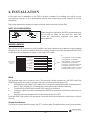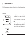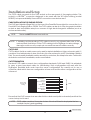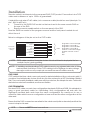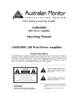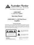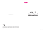
1
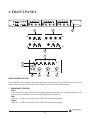
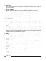
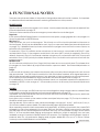
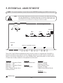
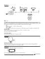
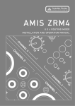
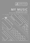
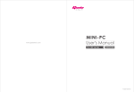
Australian Monitor
INSTALLATION
SERIES
Clever Features, Contractor Friendly
ZoneMix3
3 Zone Stereo Mixer/Matrix
Installation
&
Operation
Manual
PAGE MIC
ZONE 1
PROG TRIM
100Hz
GAIN
BASS
TREBLE
PROG 1
PROG 2
MIC/LINE 1
PROG 3
300Hz
MIC/LINE 2
Remote Status
4 5 6
3
BASS
TREBLE
GAIN
BASS
10kHz
100Hz
300Hz
1kHz
Australian Monitor
ZONE 3
ZONE 2
3kHz
TREBLE
8
9
1
1
2
MIC/LINE
4 5 6
7
2
GAIN
1kHz
3kHz
10kHz
100Hz
300Hz
1kHz
3kHz
10kHz
INSTALLATION SERIES
PROG 4
0
10
LEVEL
3
1 2 3
7
4
Off
Remote Status
8
2
0
10
LEVEL
SELECT
2
MIC/LINE
4 5 6
7
8
9
1
1
PROGRAM
4 5 6
3
2
9
1
0
10
LEVEL
3
1 2 3
7
4
Off
Remote Status
8
2
0
10
LEVEL
SELECT
2
MIC/LINE
4 5 6
7
8
9
1
1
PROGRAM
4 5 6
3
2
9
1
0
10
LEVEL
3
1 2 3
7
POWER
4
Off
8
2
9
1
0
10
LEVEL
PROGRAM
SELECT
ZoneMix3
Internal Revision Info
Rev 1 10/12/03
Rev 2 05/02/04
Rev 3 09/03/04
AUS, EUR, USA
Copyright 9th Mar 2004
Rev A: 9th Mar 2004
This symbol is intended to alert the user to the
presence of uninsulated “dangerous voltage”
within the product’s enclosure that may be of
sufficient magnitude to constitute a risk of electric
shock to persons.
CAUTION
RISK OF ELECTRIC SHOCK
DO NOT OPEN
CAUTION: TO REDUCE THE RISK OF ELECTRIC SHOCK.
DO NOT REMOVE COVER (OR BACK).
This symbol is intended to alert the user to the
presence of important operation and maintenance (servicing) instructions in the literature
accompanying the appliance.
NO USER-SERVICEABLE PARTS INSIDE.
REFER SERVICING TO QUALIFIED SERVICE PERSONNEL.
WARNING !
To prevent electric shock do not use this (polarized) plug
with an extension cord, receptacle or other outlet unless
the blades can be fully inserted to prevent blade exposure.
TO REDUCE THE RISK OF FIRE OR ELECTRIC SHOCK.
DO NOT EXPOSE THIS EQUIPMENT TO RAIN OR MOISTURE.
To prevent electric shock, match wide blade of plug to
wide slot, fully insert.
Caution:
Australian Monitor
INSTALLATION SERIES
2
CONTENTS
1. Introduction
Page
4
2. Front Panel
5
3. Back Panel
7
4. Functional Notes
9
5. Internal Adjustments
10
6. Installation
13
7. SetUp (Step by Step)
15
8. ZM3M - Paging Station
16
9. ZM3R - Remote Control Panel
18
10. Dimensions
21
11. Block Diagram
22
12. Specifications
23
Australian Monitor
INSTALLATION SERIES
3
1. INTRODUCTION
The Australian Monitor Zone Mix 3 is an extremely versatile & innovative mixer & signal router.
Featuring a broadcast quality audio spec, the Zone Mix 3 allows selection of 4 stereo sources
to 3 stereo zones either at the ZoneMix3 or remotely. One stereo source can have selectable
priority per zone & each stereo zone boasts 5 stage equalization. The Zone Mix 3 also has the
ability to route two independent mic or line signals to any zone or combination of zones. Add
to this remote volume controls in each zone & the ZM3M 3 zone paging microphone (both
running via inexpensive CAT5 cabling) and you have an extremely high quality Zone
selecting mixer at a fraction of the cost of other products in this market.
Australian Monitor
INSTALLATION SERIES
4
2. FRONT PANEL
PAGE MIC
ZONE 1
PROG TRIM
300Hz
100Hz
GAIN
BASS
TREBLE
PROG 1
PROG 2
MIC/LINE 1
PROG 3
MIC/LINE 2
Remote Status
4 5 6
3
BASS
TREBLE
GAIN
BASS
TREBLE
2
MIC/LINE
3
8
300Hz
100Hz
GAIN
4
Off
Remote Status
8
3kHz
1kHz
0
10
LEVEL
4 5 6
3
10kHz
PROGRAM
SELECT
2
MIC/LINE
3
8
300Hz
100Hz
1kHz
8
0
10
LEVEL
3kHz
10kHz
PROGRAM
SELECT
MIC/LINE
INSTALLATION SERIES
PROG TRIM
PROG 2
MIC/LINE 1
7
8
10
0
LEVEL
3
1 2 3
7
POWER
4
Off
8
2
9
1
0
10
LEVEL
PROGRAM
ZoneMix3
SELECT
9
PAGE MIC
PROG 1
2
4 5 6
9
1
2
TREBLE
3
2
1
1
BASS
GAIN
Remote Status
4
Off
4 5 6
9
1
10
0
LEVEL
1 2 3
7
2
9
1
1
4 5 6
7
2
9
1
10
0
LEVEL
1 2 3
7
2
9
1
1
4 5 6
7
2
GAIN
10kHz
Australian Monitor
ZONE 3
ZONE 2
3kHz
1kHz
PROG 4
PROG 3
PROG 4
MIC/LINE 2
BASS
TREBLE
GAIN
BASS
TREBLE
3
4
ZONE 2
100Hz
5
6
Remote Status
300Hz
4 5 6
3
8
9
1
2
MIC/LINE
7a
3kHz
10kHz
4 5 6
7
2
1
1kHz
3
9
1
0
10
LEVEL
8a
7b
4
Off
8
2
10
0
LEVEL
1 2 3
7
PROGRAM
SELECT
8b
INPUT CONTROL SECTION
Note that there are security panels covering the input section and zone EQ section when first
removed from the box. These should be used to prevent incidental tampering.
1. PAGING MIC CONTROL
Gain
This controls the gain of the optional Paging Station microphone. See Paging Station on
page 16 for more information on the Paging Station and its use.
Bass
There is +/-12dB of cut and boost at 100Hz. This eq is shelving type.
Treble
There is +/-10dB of cut and boost at 10kHz. This eq is shelving type.
Australian Monitor
INSTALLATION SERIES
5
2. PROG TRIM
These four pots control the input trim of the corresponding program inputs. There is no
gain from these pots.
3. MIC/LINE CONTROLS
There are two Mic/Line inputs. The following controls are duplicated for each input.
Gain
This controls the gain of the Mic (on the XLR) or Line (on the RCA) input.
Bass
There is +/-12dB of cut and boost at 100Hz. This eq is shelving type.
Treble
There is +/-10dB of cut and boost at 10kHz. This eq is shelving type.
ZONE OUTPUT SECTION
4. EQ
The zone eq is 5 band with frequency centres at 100Hz, 300Hz, 1kHz, 3kHz and 10kHz.
There is +/- 9dB of cut and boost. The eq is internally defeatable, see Internal Adjustments
on page 10.
5. STATUS
This LED gives an indication of OUTPUT signal . It glows green at -30dB and red at 0dBV (1V).
This is meant to indicate clip within the system (ie when the amplifier is clipping) rather
than indicate clip within the ZoneMix3. When used with Australian Monitor Synergy
amplifiers, both LEDS on the ZoneMix3 and the Synergy amplifier will go red simultaneous
indicating system clip (with pot at full on amplifier).
6. REMOTE
This LED indicates that the zone is in remote control mode. The program select and
volume on the front panel are disabled and are now controlled by the optional remote
control panel ZM3R, see Remote Control Panel on page 18.
7. MIC/LINE Control
7a.SELECT
These two push button switches are used to select either or both of the two MIC/LINE inputs
to this zone.
7b.LEVEL
This pot controls the mixed level of the two MIC/LINE inputs in this zone.
8. PROGRAM Control
8a.SELECT
This rotary 5 way switch is used to select which program input is selected to this zone.
8b.LEVEL
This controls the level of the program in this zone.
9. POWER Led
This LED indicates there is power to the unit.
Australian Monitor
INSTALLATION SERIES
6
3. BACK PANEL
ENABLE
ZONE 2
REMOTE
ACPOWER
MIC/LINE 2
PROGRAM SOURCE
ZONE 1
REMOTE
REMOTE
1
3
MIC/LINE 1
SUM IN
ENABLE
ZONE 3
EARTH
4
5
10
ENABLE
9
LINK
LEFT
RIGHT
LEFT
8
RIGHT
6
PIN 2
HOT
+
LEFT
LINE 4
RIGHT
LINE 3
LINE 1
MIC2
LINE2
LINE1
MIC1
PAGE MIC
2
7
PIN 1
GND
LINE 2
PIN 2
HOT
+
PIN 1
GND
PIN 3
COLD
-
PIN 3
COLD
MALE XLR
FEMALE XLR
1. SUM INPUT
This RCA line level input is an all zone priority input. See Functional Notes on page 9. The
volume control is preset internally and can be adjusted. See Internal Adjustments on page
10. It can be used to receive an emergency evacuation tone or similar signal.
2. PAGE INPUT
This RJ45 connector accepts a CAT5 cable from the optional ZM3M Paging Station. See
Paging Station on page 16 for more details.
NOTE:
These are NOT Ethernet connections.
3. MIC/LINE INPUTS
There are two MIC/LINE inputs. The balanced XLR inputs accepts mic level signals. The
dual RCA inputs accept line level inputs and are summed to mono internally. Gain and EQ
are controlled from the front panel.
These inputs supply 15V phantom power, unless internally disabled. See Internal
Adjustments on page 10.
These inputs may have priority over program inputs, if this feature is enabled. See Internal
Adjustments on page 10 and Functional Notes on page 9.
4. PROG INPUTS
There are four program inputs. These are stereo RCA line level inputs. Trim is controlled from
the front panel. LINE4 is a priority input, if this feature is enabled. See Internal Adjustments
on page 10 and Functional Notes on page 9
5. ZONE OUTPUTS
The zone outputs are configured as stereo left and right as default but can be internally
changed to mono.
Australian Monitor
INSTALLATION SERIES
7
6. REMOTE PORT
This CAT5 socket is used to connect the optional ZM3R remote control panel for each
zone. See Installation Section on page 13 and Remote Control Panel Section on page 18.
7. REMOTE ENABLE
This button puts the zone into remote mode and must be pressed in when using the
remote control panel ZM3R. When pressed, the front panel program controls (SELECT and
LEVEL) will be disable. Control is handed over to the remote control panel. If no remote
control panel is connected, the program inputs will be off.
8. LINK
This 15 pin high density connector is used to connect two ZoneMix3 units together. When
connected together the program sources and the mic/line inputs are linked to the slave
unit. The unit needs to be internally configured as master or slave. This is done by moving
the link cable. See Internal Adjustments on page 10.
9. EARTH
In some circumstances it may be necessary to ground the unit to eliminate noise in the
system. This can be done by using this earth stud.
NOTE: This stud provides a connection to chassis ground. Audio ground is internally
tied to chassis ground.
10. AC POWER
This 2.1mm connector accepts power from the provided 20VAC power supply.
Australian Monitor
INSTALLATION SERIES
8
4. FUNCTIONALNOTES
There are many features hidden in this product that greatly enhance its value. However, it’s important
to understand how these features work in order to get the best out of the product.
PRIORITY INPUTS
Sum in
Signal on this input will mute program in ALL zones. Level is preset internally and can be adjusted. See
Internal Adjustments on page 10.
This input can be used to receive an emergency evacuation tone or similar signal.
Page mic
If the optional ZM3M Paging Station is connected to the system, paging signals will mute program in
the zones selected on the ZM3M only.
Mic/Line 1,2
These inputs are set up to mute program. This will only occur if the input is selected into the zone on
the front panel. Priority can be disabled for each input, on a per-zone basis (See Internal Adjustments
on page 10). If disabled these inputs are mixed with the program sources into the zone outputs, as
selected on the front panel.
For example, if Zone 2 is a Bistro and a microphone in the servery is connected to MIC/LINE 1 input
and selected in Zone 2, the program would duck in this zone (MIC1 priority is enabled in Zone 2 by
default). However if Zone 3 is a bar and a karioke microphone is connected to MIC/LINE 2 input and
selected in Zone 3, MIC2 priority should be disabled in Zone 3 so that the microphone will mix with the
program source .
Release time
All of the above priority inputs (Sum, Page, Mic/Line) share a common priority level. The release time
(for program to come back up) may be selected on a per-zone basis. See Internal Adjustments on
page 10.
Prog 4
In venues with a Juke box, the Jukebox should over-ride (mute) any other background music sources
that are selected. The LINE4 input is used for this. With this feature enabled, when signal appears on
LINE4 it will automatically be selected even if not selected on the front panel or remote control panel.
PROG4 priority may be enabled on a per-zone basis. See Internal Adjustments on page 10.
It is undesirable to cut back to other BGM between tracks, so a separate release time adjustment is
available for PROG4, with a range of 1-25 seconds (common to all zones). See Internal Adjustments
on page 10.
LINKING
If 3 zones is not enough, two ZM3s can be connected together using a single cable in a Master-Slave
configuration and enabling this feature. See Internal Adjustments on page 10.
The Master unit will accept all the input sources (both Mic/Line inputs and program inputs), and these
will be passed to the Slave unit.
Input gain or trim controls on the master unit are used (see Setup on page 15). The input controls on
the slave unit will have no effect.
Use high density 15pin male to male cable wired straight through (pin1 to pin1, pin2 to pin2, etc). A
VGA monitor cable may be suitable. This cable should be kept as short as possible.
When operating a system that incorporates two linked ZM3’s, a ZM3M connected to the master ZM3
will page into the zones assigned to the master ZM3 only. Similarly, a ZM3M connected to the slave
ZM3 will page into the zones assigned to the slave ZM3 only. It is not possible to page ‘across’ linked
ZM3’s. If a more sophisticated paging and program distribution matrix is required, then we have
available a range of products ideally suited to the purpose. Our DigiPage and DigiPageJr family of
products allow for comprehensive paging and program distribution into up to 16 zones. Please
contact your local AMIS dealer for more details.
Australian Monitor
INSTALLATION SERIES
9
5. INTERNAL ADJUSTMENT
NOTE: To avoid frustration, check this section BEFORE installing your ZM3 in the rack!
NOTE:
The following adjustments involve access to the inside of the ZM3 and should
only be attempted by a qualified technician. All internal adjustments are
accessible by removing the lid of the ZM3. Always turn off the AC power and
remove the power cord before accessing the inside of the ZM3.
X4/1
X1/1
X2/1
Section A
P/P
X3/1
P/P
ON OFF
HP-160Hz
Sum Gain
Adjust
OFF
ON
ON
OFF
OFF ON
HP-160Hz
MIC 2
MIC 1
Section E
RELEASE TIME
1sec
25sec
X20/1
X19/1
EN
5
15
EN
MIC2
PRIORITY
PROG 4
PRIORITY
STEREO
X16/1
0.5
X14/1
EN
MIC1
X15/1
5
X7/1
secs
MUTE
RELAESE
EN
ZONE 1
MONO
15
EN
MIC2
X13/1
0.5
X11/1
EN
MIC1
PRIORITY
PROG 4
PRIORITY
STEREO
X6/1
X5/1
secs
MUTE
RELAESE
X12/1
5
15
X9/1
X10/1
0.5
X8/1
EN
MIC2
MONO
LINK - SLAVE
EN
MIC1
PRIORITY
PROG 4
PRIORITY
STEREO
LINK - MASTER
MONO
secs
MUTE
RELAESE
EN
ZONE 2
ZONE 3
Section D (repeated 3 times)
Section B
R137
Chime Level
Adjust
Section C (repeated 3 times)
SW8
SW7
SW9
There are many internal adjustments that can be made to configure the ZoneMix3 to
perform exactly as you want it. Use the diagram above to locate various controls and
refer to the section indicated for a more detailed view and information on that control.
Controls are clearly marked on the printed circuit board.
Section A
Mic/Line 1 - Phantom Power
Mic/Line 1 - HPF
Mic/Line 2 - Phantom Power
Mic/Line 2 - HPF
Prog 4 Priority release time
Sum Input level
Section B
Paging Chime level
Section C
Zone Eq Bypass
Section D
Mic/Line 1 Priority
Mic/Line 2 Priority
Priority Release Time
Program 4 Priority
Output Mono/Steroe Mode
Section E
Unit Link Setting
Australian Monitor
INSTALLATION SERIES
10
SECTION A
MIC 1, 2
NOTE: PCB markings should be noted carefully as MIC2 is a mirror image of MIC1.
MIC1 refers to MIC/LINE 1 input, and MIC2 refers to MIC/LINE 2 input.
P/P
Phantom Power +15VDC. Default is ON.
HPF - 160Hz
The high pass filter has a crossover at 160Hz and a slope of -6dB/oct. Default is OFF.
RELEASE TIME
Prog 4 Priority release time trimpot 1sec-25sec - Default is 10sec.
See Functional Notes on page 9.
Sum Gain Adjust
Sum Input level 0dB to Off - Default is -6dB.
SECTION B
Chime Level Adjust
This pot is for the chime that sounds when a page is made using the Paging Station.
Paging Chime level 0dB to Off - Defaults is -6dB.
EQ OUT
EQ IN
SECTION C
This section is repeated 3 times (one per zone).
Zone Eq Bypass switch - Eq In/Eq Out. Default is Eq In.
Australian Monitor
INSTALLATION SERIES
11
SECTION D
This section is repeated 3 times (one per zone).
MIC1 refers to MIC/LINE1 input, and MIC2 refers to MIC/LINE2 input.
See Functional Notes on page 9 for explanation of priority functions.
PRIORITY
MIC1, 2
Default is EN (enabled).
MUTE RELEASE
Priority Release Time jumper socket - 0.5,5,15 sec. Default is 5sec.
PROG 4 PRIORITY
Program 4 Priority jumper socket - Default is EN (enabled).
MONO-STEREO
Output Mode switch - Mono/Stereo. Default is Stereo.
SECTION E
These two sockets are used when linking two
ZoneMix3 units.
See Functional Notes on page 9 for explanation of
linking.
All input sources are connected to the Master unit. In
this unit the linking header should be plugged into
the connector labelled LINK-MASTER.
In the other (Slave) unit, the linking header should be
moved to the connector labelled LINK-SLAVE.
By default, all units ship as Masters.
Australian Monitor
INSTALLATION SERIES
12
6. INSTALLATION
In its basic form, installation of the ZM3 is simply a matter of mounting the unit in a rack,
connecting sources to the appropriate inputs and connecting zone outputs to power
amplifiers.
The power supply should be securely mounted, and connected to the ZM3.
NOTE: XLR CONFIGURATION
PIN 2
HOT
+
PIN 1
GND
PIN 2
HOT
+
PIN 1
GND
PIN 3
COLD
-
PIN 3
COLD
FEMALE XLR
MALE XLR
When wiring the outputs on the ZM3 as unbalanced,
Pin2 should be wired as hot and Pin1 and Pin3
should be connected together and wired as
ground/shield.
REMOTE CONTROLS
The remote control options on the ZoneMix3 are quite extensive and permit many possible
situations to be accommodated. Remote control is achieved via the rear panel RJ45 (CAT5)
socket. Below is a diagram of the pin out on the CAT5 cable.
PIN
Shown with
locking clip
facing
White/Green 1
Green 2
White/Orange 3
Blue 4
White/Blue 5
Orange 6
White/Brown 7
Brown 8
CABLE
1 Prog Select control Voltage
2 Prog Select control Bit 1
3 Prog Select control Enable
4 Prog Select control Bit 0
5 Volume control Ref Voltage
6 Program Volume control
7 Output Right Volume control
8 Output Left Volume control
568A configuration
ZM3R
The simplest and most common use of the remote control features on the ZM3 is with the
ZM3R Program Source select and level remote control panel (See page 18).
A straight through wired Cat5 cable (not a crossover cable) should be used (wired pin1
!
to pin1, pin2 to pin2 etc, following the colour system as indicated above)
Connect to the ZM3R which has a RJ45 socket on the back.
!
Connect cable from remote panel(s) to REMOTE connector in relevant zone section of
!
the ZM3.
Press the remote enable switch on the rear panel of the ZM3.
!
Now the ZM3R has control of the program sources and the front panel controls do not effect
the unit.
Simple Zone Masters
For volume control within the zone, an RC1 can be used. This will provide control over a stereo
Australian Monitor
INSTALLATION SERIES
13
zone or individual sends on a mono zone. There is no need to enable the rear panel remote
switch unless an ZM3R is also being used.
For Stereo the RC1 should be wired between pin 5 and pins 7 and 8 shorted together.
If each output is being used as an individual sub zone send then one RC1 can be wired
between pin 5 and pin7 (for Right sub zone send) and another RC1between pin 5 and pin 8
(for Left sub zone send). The zone should be set to MONO, see Internal Adjustments on page
10.
PAGING STATION
See Paging Station on page 16 for more inforamtion.
Connect cable from ZM3M to PAGE MIC connector on the ZM3.
Australian Monitor
INSTALLATION SERIES
14
7. STEP BY STEP SETUP
NOTE: To avoid frustration, check the Internal Adjustments section BEFORE
beginning setup!
The inputs of the ZM3 can accommodate a wide range of sources including active paging
stations, dynamic microphones, DVD, CD players & DJ mixers. The zone outputs may be used
to drive stereo power amplifiers, mixers, or mixer amplifiers.
Each installation will require setting the appropriate relative mix of levels between paging,
program sources and mic/line inputs for each zone and balancing between the zones.
Because of the variation in levels between the possible sources, ZM3 offers a number of gain
stage adjustments so you can set the correct levels for your application.
Also consider what the outputs are driving….
Setting up correct gain structure through the whole system is important to achieve optimal
results.
The following step by step procedure has been devised to assist during the setup process.
Step by step setup
Ensure all gain adjustments on the ZM3 are at minimum.
Choose a zone that is conveniently located near to the ZM3 or further away if you feel
you need the exercise.
This will be the referred to as the “TEST ZONE”.
Ensure that all amplifiers connected to the ZM3 are set to provide required sound levels
with a line level input signal.
1. Select PROG1 in the TEST ZONE. Adjust the PROG TRIM until sufficient level is achieved in the
TEST ZONE.
2. Repeat this process for Programs 2-4. The level of each program source should be of
similar volume so no great variation in level apparent when selecting between program
inputs
3. Check program level in the other 2 zones to confirm that the gain structure is appropriate
for all amplifiers.
4. Do a test page in the TEST ZONE and check the level relative to the program level.
5. Adjust the page level as desired [front panel PAGE MIC].
6. EQ the paging mic as required
7. Set the Mic/Line input levels remembering these inputs are selectable to each zone
from the front panel.
8. EQ the Mic/Line inputs.
9. Select the REMOTE ENABLE switch (rear panel) if the ZM3R is being used in each zone.
This will allow remote source selection & zone volume adjustment.
10. The ZM3 features 5 band equalization to achieve precise equalization of high quality
audio systems in demanding environments.
11. Repeat this process for the other 2 zones.
Australian Monitor
INSTALLATION SERIES
15
8. PAGING STATION
Introduction
The ZM3M is a slim line paging microphone that provides the user the ability to page into any
combination of zones from a remote location. Running both audio & data down inexpensive
& industry standard CAT5 cable the ZM3M is simple to install.
Controls
1 ZONE select
These buttons, when pressed, will page to that
zone. With the button held down, talk into the
microphone. There is a label space to the
right of the button to allow labelling of the
zone.
115.0mm
Australian Monitor
178.0mm
ZM3M
INSTALLATION SERIES
2. ALL page
This button allows paging to all zones. Hold
down the button to talk.
1
2
2
3
1
Base Plate
section
3 GAIN
To accommodate different speech levels,
there is a gain control on the base of the
ZM3M. This ships set to minimum and may be
adjusted to suit. Increasing this control too far
may cause the paging station to distort if loud
or close speech levels are encountered.
Caution should be used if trying to achieve
high gain levels for distant or lectern speech
styles as feedback may occur.
3
Australian Monitor
INSTALLATION SERIES
16
Installation and Setup
The CAT5 cable connects to the RJ45 socket on the rear panel of the paging station. This
socket is a NEUTRIKTM connector designed to be used with the XLR style housing (model
NE8MC) to improve reliability. Normal RJ45 connectors can also be used.
CABLE INSTALLATION FOR PAGING STATION
The RJ45 port (labelled Page Mic) on the rear of the ZoneMix3 is provided for connection to a
ZoneMix3 Zone Paging Station, ZM3M. The CAT5 cable can be up to 30m long and should be
routed as best as possible away from sources of high electromagnetic radiation (such as
motors and dimmers).
NOTE:
These are NOT Ethernet connections.
NOTE: If installing and terminating CAT5 cable is new to you, please take note of the
various points that follow. As the CAT5 cabling for the DigiPageJr carries voltage,
damage could occur if your pin-pin connections are not made correctly.
CAT5 CABLE
CAT5 cable is the blue cable commonly used for data installations (other colours do exist). It
consists of four twisted pairs of wires: this is why it is often referred to as UTP (Unshielded Twisted
Pair). The most readily available cable uses solid conductors, like telephone wire. Cable with
stranded conductors is available, and is more flexible.
CAT5 TERMINATION
Pre-wired CAT5 cable comes in two configuration standards, 568A and 568B. It is advisable
to carry a good pre-wired cable for fault-finding. Both configurations will work with the
DigiPageJr provided both ends have the same configuration. Be careful not to use a
crossover cable which has one configuration at one end and the other configuration at the
other end.
Shown with
locking clip
facing
White/Green 1
Green 2
White/Orange 3
Blue 4
White/Blue 5
Orange 6
White/Brown 7
Brown 8
CABLE
568A configuration
Ensure that the RJ45 connectors are suited to the cable used (solid or stranded) and that the
correct crimp tool is used.
NOTE: CAT5 cable consists of four pairs of wires: it is not sufficient to simply wire the two
ends pin for pin, ignoring pairing.
Australian Monitor
INSTALLATION SERIES
17
9. ZM3R REMOTE CONTROL PANEL
RJ45 CAT5
Socket
1
2
3
OFF
4
PROGRAM SELECT
4
5
6
7
3
8
2
1
9
10
0
VOLUME
ZM3R
Introduction
The ZM3R is a simple yet stylish accessory for the Zonemix 3 that allows for source
selection & volume control from a remote zone. It features ample label space and a
contemporary black decor. Running via industry standard CAT5 cable, the ZM3R is
another product from Australian Monitor Installation Series that provides a simple yet
elegant solution to a complex zoning application.
Australian Monitor
INSTALLATION SERIES
18
Installation
Remote control is achieved via the rear panel RJ45 (CAT5) socket. Connection is via CAT5
cable and a distance of up to 1000m is guaranteed.
A straight through wired Cat5 cable (not a crossover cable) should be used (wired pin1 to
pin1, pin2 to pin2 etc)
Connect to the ZM3R RJ45 socket on the back and to the zone remote RJ45 on
!
the rear of the ZM3.
Press the remote enable switch on the rear panel of the ZM3.
!
Now the ZM3R has control of the program sources and the front panel controls do not
effect the unit.
Below is a diagram of the pin out on the CAT5 cable.
Shown with
locking clip
facing
White/Green 1
Green 2
White/Orange 3
Blue 4
White/Blue 5
Orange 6
White/Brown 7
Brown 8
CABLE
Prog Select control Voltage
Prog Select control Bit 1
Prog Select control Enable
Prog Select control Bit 0
Volume control Ref Voltage
Program Volume control
N/C
N/C
568A configuration
NOTE: CAT5 cable consists of four pairs of wires: it is not sufficient to simply wire the two
ends pin for pin, ignoring pairing.
NOTE: If installing and terminating CAT5 cable is new to you, please take note of the
various points that follow. As the CAT5 cabling for the DigiPageJr carries voltage,
damage could occur if your pin-pin connections are not made correctly.
CAT5 CABLE
CAT5 cable is the blue cable commonly used for data installations (other colours do exist). It
consists of four twisted pairs of wires: this is why it is often referred to as UTP (Unshielded Twisted
Pair). The most readily available cable uses solid conductors, like telephone wire. Cable with
stranded conductors is available, and is more flexible.
CAT5 TERMINATION
Pre-wired CAT5 cable comes in two configuration standards, 568A and 568B. It is advisable to
carry a good pre-wired cable for fault-finding. Both configurations will work with the
DigiPageJr provided both ends have the same configuration. Be careful not to use a
crossover cable which has one configuration at one end and the other configuration at the
other end.
Ensure that the RJ45 connectors are suited to the cable used (solid or stranded) and that the
correct crimp tool is used.
NOTE:
These are NOT Ethernet connections.
Australian Monitor
INSTALLATION SERIES
19
Dimensions
51 mm
116 mm
100 mm
84 mm
96 mm
Panel (ZM3R)
75 mm
Surface Mount Box
35 mm
18 mm
88 mm
122 mm
44 mm
80 mm
Australian Monitor
INSTALLATION SERIES
20
10. DIMENSIONS
44.0 mm
32.0 mm
482.0 mm
467.0 mm
PAGE MIC
ZONE 1
PROG TRIM
100Hz
GAIN
BASS
TREBLE
PROG 1
PROG 2
MIC/LINE 1
PROG 3
300Hz
MIC/LINE 2
Remote Status
4 5 6
3
BASS
TREBLE
GAIN
BASS
100Hz
8
9
1
TREBLE
1
2
MIC/LINE
4 5 6
7
2
GAIN
10kHz
300Hz
1kHz
Australian Monitor
ZONE 3
ZONE 2
3kHz
1kHz
3kHz
10kHz
300Hz
100Hz
1kHz
3kHz
10kHz
INSTALLATION SERIES
PROG 4
0
10
LEVEL
3
1 2 3
7
4
Off
Remote Status
8
2
0
10
LEVEL
4 5 6
3
4 5 6
7
8
2
9
1
9
1
1
PROGRAM
SELECT
2
MIC/LINE
0
10
LEVEL
3
1 2 3
7
4
Off
Remote Status
8
2
0
10
LEVEL
4 5 6
3
8
9
1
1
PROGRAM
SELECT
2
MIC/LINE
4 5 6
7
2
9
1
3
1 2 3
7
POWER
4
Off
8
2
9
1
0
10
LEVEL
0
10
LEVEL
PROGRAM
ZoneMix3
SELECT
443.0 mm
ZONE 1
REMOTE
ENABLE
ZONE 2
REMOTE
ENABLE
16V AC
MIC/LINE 2
PROGRAM SOURCE
REMOTE
MIC/LINE 1
SUM IN
ENABLE
ZONE 3
EARTH
LINK
LEFT
RIGHT
LEFT
RIGHT
LEFT
RIGHT
LINE 4
LINE 3
LINE 2
LINE 1
MIC2
LINE2
LINE1
MIC1
PAGE MIC
268.5 mm
18.0 mm
Australian Monitor
INSTALLATION SERIES
21
11. BLOCK DIAGRAM
L
LINE 1
ZONE 1
PROG
SELECT
+12dB
R
5-BAND
EQ
Z1 PROG VOL
6dB
-6dB
+12dB
SIG/OL
EQ
IN/OUT
L
Z1 PROG SEL
STEREO/MONO
-6dB
LINE 2
+12dB
R
ZONE 2
PROG
SELECT
Z2 PROG VOL
ZONE 3
PROG
SELECT
Z3 PROG VOL
L
ZONE VOLUME
CONTROL USING RV-1
(OPTIONAL)
ZONE 1
ZONE VOLUME
CONTROL USING RV-1
(OPTIONAL)
5-BAND
EQ
6dB
R
6dB
L
+12dB
L
LINE 3
Z2 PROG SEL
+12dB
R
5-BAND
EQ
+12dB
L
-6dB
SIG/OL
EQ
IN/OUT
LINE 4
STEREO/MONO
RELEASE TIME
+12dB
1sec
R
-6dB
25sec
Z3 PROG SEL
SIG
DETECT
+12dB
PROGRAM
LINK
IN/OUT
CONNECTOR
-23dB
SIG
DETECT
MIC1 DET
ZONE VOLUME
CONTROL USING RV-1
(OPTIONAL)
ZONE 2
ZONE VOLUME
CONTROL USING RV-1
(OPTIONAL)
5-BAND
EQ
PROG4 DET
6dB
R
6dB
L
MIC 1 SELECT
ZONE 1
MIC 2 SELECT
-23dB
0dB
Z1 MIC
LEVEL
37dB
HPF
5-BAND
EQ
EQ
MIC 1 SELECT
ZONE 2
MIC 2 SELECT
12dB
SIG
DETECT
-23dB
0dB
-6dB
MIC2 DET
SIG/OL
EQ
IN/OUT
Z2 MIC
LEVEL
-23dB
STEREO/MONO
-6dB
37dB
HPF
MIC 1 SELECT
ZONE 3
MIC 2 SELECT
EQ
ZONE VOLUME
CONTROL USING RV-1
(OPTIONAL)
ZONE 3
ZONE VOLUME
CONTROL USING RV-1
(OPTIONAL)
6dB
5-BAND
EQ
R
12dB
Z3 MIC
LEVEL
PAGING
MIC
ZONE
SELECT
EQ
0dB
ZONE 1
REMOTE
/LOCAL
SELECT
5V
ZONE 1
PROG
LEVEL
TONE IC
REMOTE
ENABLED
CHIME
LEVEL
PROG 4
PRIORITY
ZONE 1
PROG
SELECT
OFF,1,2,3,4
ZONE 1
SELECT
CONTROL
Z1 PROG SEL
MIC1
DET
MIC2
DET
SUM
DET
MIC 1
SELECT
ZONE 1
MUTE
CONTROL
PIC
MIC 2
SELECT
ZONE 2
REMOTE
INPUT
PROG4 DET
ZONE 2
REMOTE
LOCAL
SELECT
5V
MIC1 DET
ZONE 2
PROG
LEVEL
MIC2 DET
SUM DET
REMOTE
ENABLED
PROG 4
PRIORITY
ZONE 2
PROG
SELECT
OFF,1,2,3,4
ZONE 2
SELECT
CONTROL
Z2 PROG SEL
MIC1
DET
MIC2
DET
SUM
DET
MIC 1
SELECT
ZONE 2
MUTE
CONTROL
PIC
MIC 2
SELECT
ZONE 3
REMOTE
INPUT
ZONE 3
REMOTE
LOCAL
SELECT
5V
REMOTE
ENABLED
PROG 4
PRIORITY
ZONE 3
PROG
SELECT
OFF,1,2,3,4
ZONE 3
PROG
LEVEL
ZONE 3
SELECT
CONTROL
Z3 PROG SEL
MIC1
DET
MIC2
DET
SUM
DET
Australian Monitor
INSTALLATION SERIES
22
MIC 1
SELECT
MIC 2
SELECT
ZONE 3
MUTE
CONTROL
PIC
SIG
DETECT
SUM INPUT
ZONE 1
VOLUME
CONTROL
CIRCUITRY
0dB
Z1 PROG VOL
ZONE 1
MUTE RELEASE TIME
0.5 SEC
5 SEC
15 SEC
ZONE 1
REMOTE
INPUT
0dB
ZONE 2
VOLUME
CONTROL
CIRCUITRY
Z2 PROG VOL
ZONE 2
MUTE RELEASE TIME
0.5 SEC
5 SEC
15 SEC
Off
ZONE 3
VOLUME
CONTROL
CIRCUITRY
Z3 PROG VOL
ZONE 3
MUTE RELEASE TIME
0.5 SEC
5 SEC
15 SEC
REMOTE
PAGE LEVEL
REMOTE
PAGING
INPUT
SUM
LEVEL
SUM DET
12. SPECIFICATIONS
-Dimensions:
44.0 x 482.0 x 286.5 (HxWxD) mm
-Weight:
Net 2.5kg Shipping 3.0kg
Net 5.5lb Shipping 6.6lb
-Power Input:
20VAC
30VA max
-Sensitivity (for 0dB out):
Mic/Line Input (RCA)
86mV (-19dB)
Mic/Line Input (XLR)
1.55mV (-54dB)
Prog Input (RCA)
190mV (-12dB)
-Max Level Out:
10Vrms (+22dB)
-Frequency Response:
(0dB/-3dB)
20Hz - 20kHz
-THD:
less than 0.1%
-Noise:
-80dB
-Crosstalk:
Better than 65dB
-Phantom Power:
15VDC
All measurements referenced to 0dBu (0.775mV)
All measurements done with levels set to max
Australian Monitor
INSTALLATION SERIES
23
AUSTRALIA and NEW ZEALAND
www.australianmonitor.com.au
Sydney
(NSW & ACT Sales)
Private Bag 149, Silverwater NSW 1811
149 Beaconsfield Street, Silverwater NSW 2128
Ph: (02) 9647 1411
Fax: (02) 9648 3698
E-mail: [email protected]
Brisbane
(Qld Sales)
P.O. Box 871, Fortitude Valley QLD 4006
42 Commerical Road, Fortitude Valley QLD 4006
Ph: (07) 3852 1312
Fax: (07) 3252 1237
E-mail: [email protected]
Perth
(WA Sales)
Melbourne
(Vic & Tas Sales)
Adelaide
(SA & NT Sales)
Auckland
(NZ Sales)
P.O. Box 151, Blackburn South VIC 3130
22/277 Middleborough Road, Box Hill VIC 3128
Ph: (03) 9890 7477
Fax: (03) 9890 7977
E-mail: [email protected]
P.O. Box 157, Hindmarsh SA 5001
31 Walsh Street, Thebarton SA 5031
Ph: (08) 8352 4444
Fax: (08) 8352 4488
E-mail: [email protected]
P.O. Box 404, North Perth WA 6906
299 Fitzgerald Street, West Perth WA 6005
Ph: (08) 9228 4222
Fax: (08) 9228 4233
E-mail: [email protected]
P.O. Box 512, Albany 1331
Unit B, 11 Piermark Drive, Albany 1331
Ph: (09) 415 9426
Fax: (09) 415 9894
E-mail: [email protected]
EUROPE/ASIA/MIDDLE EAST
www.australianmonitor.com.au
International Sales
Private Bag 149, Silverwater NSW 1811
149 Beaconsfield Street, Silverwater NSW 2128
Australia
Ph: 61-2- 9647 1411
Fax: 61-2-9748 2537
E-mail: [email protected]
USA/CANADA/SOUTH AMERICA
www.australianmonitor.com
Australian Monitor Audio Inc.
PO Box 3126, Lynnwood, WA 98046
Ph: 425 673 5175
Fax: 425 673 7825
E-mail: [email protected]
MIC/LINE 2
PROGRAM SOURCE
ZONE 1
REMOTE
ENABLE
ENABLE
ZONE 2
REMOTE
ACPOWER
REMOTE
MIC/LINE 1
SUM IN
ENABLE
ZONE 3
EARTH
LINK
LEFT
RIGHT
LEFT
RIGHT
LEFT
RIGHT
LINE 4
LINE 3
LINE 2
LINE 1
MIC2
LINE2
LINE1
MIC1
PAGE MIC