1
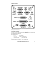
Microvision Plus User Manual SP101005.305 7 July 2009 As part of our continuous product improvement policy, we are always pleased to receive your comments and suggestions about how we should develop our product range. We believe that the manual is an important part of the product and would welcome your feedback particularly relating to any omissions or inaccuracies you may discover. You can send your comments to:MKS Instruments, Spectra Products. Cowley Way Crewe Cheshire CW1 6AG U.K. Tel: +44 (0)1270 250150 Fax: +44 (0)1270 251939 Email: [email protected] Windows is a trademark of the Microsoft Corporation. All other brand or product names are trademarks or registered trademarks of their respective companies Microvision Plus – SP101005.305 – 7 July 2009 MKS Instruments, Spectra Products 2 Declaration of Conformity Spectra SensorTech Ltd. Cowley Way Crewe Cheshire CW1 6AG United Kingdom DECLARES THAT THE FOLLOWING PRODUCTS: LM62, LM10 VACSCAN 100 LM63, LM10, LM4 VACSCAN PLUS 100, 200 LM61, LM10, LM4, LM9 SATELLITE 100, 200, 300 LM56 MICROVISION LM70, LM76 MICROVISION PLUS LM77 VISION 1000P LM78 VAC CHECK LM79 VISION 1000I LM80 MINILAB LM89 VISION 1000B LM90 VISION 1000 C / E LM92 MICROVISION IP LM98 e-Vision LM99 Cirrus LM100 300mm Resistorr LM102 e-Vision+ ARE IN CONFORMITY WITH THE FOLLOWING EUROPEAN DIRECTIVES: 2004/108/EEC ELECTROMAGNETIC COMPATIBILITY DIRECTIVE 2006/95/EC LOW VOLTAGE DIRECTIVE THE APPLICABLE STANDARDS ARE: EN 61326:1998 ELECTRICAL EQUIPMENT FOR MEASUREMENT, CONTROL & LABORATORY USE EN 61010-1:1993 SAFETY REQUIREMENTS FOR ELECTRICAL EQUIPMENT FOR MEASUREMENT, CONTROL & LABORATRY USE. SIGNED: J.M.Higgins GENERAL MANAGER DATE: 7th July 2009 Microvision Plus – SP101005.305 – 7 July 2009 MKS Instruments, Spectra Products 3 Additional Installation Maintenance and Operating Instructions In order to comply with European regulations, the following procedures must be followed: A) INSTALLATION 1. The installation procedures given in the operating and technical manuals must be followed in addition to these instructions. 2. The mains power cable must conform to local regulations and must have a protective earth (PE) conductor securely connected to the power plug protective earth contact. 3. The short earthing braid supplied with some products, must be fitted between the terminal on the RF head and one of the CF40 vacuum flange bolts. 4. Only cables supplied with the equipment may be used for interconnections. If extension cables are required to obtain a greater separation between control unit and RF head, or if longer serial communications cables are required, they must be supplied by MKS Instruments Ltd. 5. Cables attached to all other ancillary signal and control ports must have a length of less than 3 metres. If greater length is required, MKS Instruments Ltd. must be contacted for technical guidance on possible EMC and safety issues. 6. The vacuum system on which the analyser/RF head is mounted must be earthed, to a protective earth, preferably to the same protective earth as the control unit. B) OPERATION 1. The equipment is not authorised for use as a critical component in a life support or safety critical system without the express written approval of MKS Instruments Ltd. 2. All instructions given in the operating manual must be followed. Microvision Plus – SP101005.305 – 7 July 2009 MKS Instruments, Spectra Products 4 3. Adjustments are strictly limited to those accessible from the control panel and computer keyboard and only when running software supplied by MKS Instruments Ltd. C) MAINTENANCE WARNING-DANGEROUS VOLTAGES EXIST INSIDE THE EQUIPMENT 1. Maintenance functions must only be carried out by competent persons. 2. During the warranty period, faulty equipment must be returned to MKS Instruments, Spectra Products Ltd., unless special arrangements are made. 3. There are no user serviceable parts in the electronic equipment. Certain components are EMC and safety critical and must not be substituted. Replacement parts are available from MKS Instruments, Spectra Products Ltd. 4. Equipment enclosures embody certain special fastenings and bonding devices that affect EMC and safety performance. These must be correctly re-fitted after servicing. WARNING The Electron Multiplier (SEM) must not be operated at temperatures above 50oC. With dual (faraday and electron multiplier) detector instruments, serious damage will be caused to the electron multiplier if it is operated at temperatures above 500C. No damage is caused to the multiplier by high temperatures provided it is not switched on. The Microvision electronics should not be exposed to temperatures above 350C. Microvision Plus – SP101005.305 – 7 July 2009 MKS Instruments, Spectra Products 5 Contents 1. Specification ....................................................................................... 8 1.1 Mechanical ........................................................................................... 8 Microvision Plus ...................................................................................... 8 PUP80 Power Supply ............................................................................... 8 1.2 Electrical .............................................................................................. 8 1.3 Environmental ...................................................................................... 8 1.4 Safety .................................................................................................. 9 1.5 Connectors ........................................................................................... 9 1.6 Warning labels .................................................................................... 10 1.7 Ventilation .......................................................................................... 10 2. Introduction ..................................................................................... 11 2.1 General .............................................................................................. 11 2.2 User interface ..................................................................................... 12 2.2.1Power connector............................................................................ 12 2.2.2 Indicators..................................................................................... 13 2.2.3 RS232 connector .......................................................................... 14 2.2.4 RS422/485 plug and socket........................................................... 14 2.2.5 Audio output ................................................................................ 14 2.2.6 Analog I/O connector.................................................................... 15 2.2.7 Digital I/O connector .................................................................... 16 2.2.8 Reset switch................................................................................. 17 2.2.9 Volume contro.............................................................................. 17 2.2.10 External trip ............................................................................... 17 3. Analyser Installation ........................................................................ 18 3.1 Unpacking .......................................................................................... 18 3.2 Inspecting the analyser ....................................................................... 18 3.3 Installing the analyser ......................................................................... 19 3.4 Checking the system pressure ............................................................. 19 3.5 Mounting the analyser......................................................................... 20 4. Microvision Installation.................................................................... 21 4.1 Installation ......................................................................................... 21 4.2 Electrical connections .......................................................................... 21 5. Baking............................................................................................... 23 6. Analyser Maintenance ...................................................................... 24 6.1 Overview ............................................................................................ 24 1. The ion source or ioniser .................................................................. 24 2. The quadrupole filter ........................................................................ 24 3. The detector .................................................................................... 24 4. The flanged housing......................................................................... 24 6.2 Ohmmeter analyser checks.................................................................. 26 6.3 Checking filaments.............................................................................. 28 6.4 Changing filaments ............................................................................. 29 Microvision Plus – SP101005.305 – 7 July 2009 MKS Instruments, Spectra Products 6 6.4.1 Removing the filaments ................................................................ 30 6.4.2 Fitting new filaments .................................................................... 31 6.5 Ion Source cleaning ............................................................................ 32 6.6 Cleaning or replacing the ion source..................................................... 34 6.6.1 Removing the ion source............................................................... 35 6.6.2 Dismantling the source assembly ................................................... 35 6.6.3 Source Re-assembly...................................................................... 36 7. Exploded Views ................................................................................ 38 7.1 Analyser Flange pin-outs ..................................................................... 38 7.2 Exploded view of the Analyser ............................................................. 39 7.3 Filament Plate..................................................................................... 40 7.4 Source Assembly................................................................................. 41 7.5 Source Alignment Jig........................................................................... 42 7.6 Extract Plate ....................................................................................... 43 8. Returning Your Unit for Service ....................................................... 44 Microvision Plus – SP101005.305 – 7 July 2009 MKS Instruments, Spectra Products 7 1. Specification 1.1 Mechanical Microvision Plus Size: 127mm wide x 127mm deep x 180mm deep plus 34mm over analyser connector. Weight: 2.2kg PUP80 Power Supply Size: 95mm wide x 70mm high x 180mm deep plus 20mm over strain relief. Weight: 1.1kg 1.2 Electrical Power Inlet: 100 to 120, 200 to 240 V rms 47-63Hz 1.3A rms Installation category (overvoltage category) II to IEC664 Fuses Internal, not user replaceable Insulation Class I to IEC536 1.3 Environmental Temperature range 0 to 400C, 80%RH non-condensing, operating and storage. Pollution degree 2 to EN61010 Enclosure IP20 to EN60529 Microvision Plus – SP101005.305 – 7 July 2009 MKS Instruments, Spectra Products 8 1.4 Safety IP20 to EN60529 The protective earth conductor of the power cord must be connected to the power source protective earth terminal. There are no operator replaceable parts within either the PUP-80 power supply unit or the LM70 or LM76 Microvision Plus units. 1.5 Connectors The connectors for external circuits are for use only with MKS Spectra equipment, or equipment which has no accessible hazardous live parts. The external circuits must comply with the requirements of EN61010-1 section 6.6.1 Ports for connection of accessories do not carry hazardous potentials. Do not position the PUP-80 power supply so that it is difficult to unplug the mains power cord. Installation Category II comprises mains powered, local level appliances. Microvision Plus – SP101005.305 – 7 July 2009 MKS Instruments, Spectra Products 9 1.6 Warning labels On the front panel refers to: a. Accessible hazardous voltages on analyser connector, when not mated to the analyser, which may result in a non-hazardous electric stock if touched. b. Tuning adjustment holes, which are not for operator use. On the rear panel refers to: a. Read all instructions carefully before use. b. The control unit and signal ports are designed for connection to MKS Spectra accessories via MKS Spectra supplied cables. There are no accessible hazardous voltages or currents on these ports. MKS Spectra must be consulted before any non MKS Spectra cables or accessories are connected to these ports. 1.7 Ventilation Openings in the front, top and bottom panels must not be obstructed. Allow a minimum clearance of 50mm all round. Do not exceed the maximum operating ambient temperature. Microvision Plus – SP101005.305 – 7 July 2009 MKS Instruments, Spectra Products 10 2. Introduction The Microvision Plus is a complete quadrupole residual gas analyser (RGA) comprising of a quadrupole analyser, a Microvision Plus control unit, a low voltage power supply and the necessary interconnecting cables. As opposed to traditional RGA’s the Microvision Plus incorporates all of the electronics normally found in a separate control unit and RF power supply into one extremely compact unit, which fits directly onto the quadrupole analyser. Microvision Plus is designed to be operated from a host computer which will normally be an IBM compatible PC, running the Spectra Process Eye V2.0 software package. Complete RGA systems may comprise of one Microvision Plus and a PC, referred to as a single headed system or a number of Microvision Plus units connected to a single computer known as a multi-headed system. Three types of serial communication are available to meet the needs of the various system configurations. A range of accessories is available to connect to the Microvision to further extend its operational capabilities. This manual focuses on the Microvision Plus hardware and should be used in conjunction with the manual for the operating software. 2.1 General The Microvision Plus is a single unit incorporating all the necessary power supply and data acquisition electronics for the residual gas analyser. Power is derived from a dedicated low voltage power supply, which is supplied as part of the standard package. Alternatively, power may be derived from a suitable Spectra Remote Vacuum Controller if the complete system incorporates one. The Microvision plugs directly onto the quadrupole analyser via the connector mounted on the front panel of the unit. All external connections including the power supply and serial communications link are made via connectors mounted on the rear panel of the unit. Microvision Plus contains no user serviceable parts and the only manual adjustment is the volume control for the audio, which is mounted on the rear panel. Microvision Plus – SP101005.305 – 7 July 2009 MKS Instruments, Spectra Products 11 2.2 User interface Rear panel arrangement 2.2.1Power connector This is a 15-way D-Type socket labelled POWER used to connect the low voltage power supply unit. Pin connections are: 1, 2, 3 +24 volts DC 9, 10, 11 0 volts (24 volt return) Connector Shell Functional Earth The power input is 24 volts DC 10%, 2 Amps max. Microvision Plus – SP101005.305 – 7 July 2009 MKS Instruments, Spectra Products 12 The primary power circuit is galvanically isolated from the system ground. The maximum common mode voltage is 60V DC or peak AC, current Limited to 2mA. 2.2.2 Indicators On the rear panel of the Microvision Plus there are five function LED indicators, their functions are described below. 1. Filament 1 This is a green LED labelled FILAMENT 1 on the rear panel of the Microvision Plus unit. It will be illuminated when filament 1 is selected and the emission is established. If the emission is not at the selected value, it will be extinguished. 2. Filament 2 This is a green LED labelled FILAMENT 2 on the rear panel of the Microvision Plus unit. It will be illuminated when filament 2 is selected and the emission is established. If the emission is not at the selected value, it will be extinguished. 3. SEM supply This is an amber LED labelled SEM on the rear panel of the Microvision Plus unit. It will be illuminated when the multiplier detector is switched on. 4. Power on This is a red LED labelled POWER on the rear panel of the Microvision Plus unit driven from the +5V supply. It will be illuminated when power is supplied to the Microvision Plus and the +5V rail is established. 5. Comms OK This is a green LED labelled COMMS on the rear panel of the Microvision Plus unit. Its exact status is determined by the software. Microvision Plus – SP101005.305 – 7 July 2009 MKS Instruments, Spectra Products 13 2.2.3 RS232 connector This is a 9-way D-Type socket labelled RS232.It is used to connect the Microvision to the host computer when the RS232 interface is used. This socket is also configured to provide a power feed for an Amplicon 490 fibre optic converter Pin connections are: Pin Pin Pin Pin Pin 1, 7, 9 2 3 4, 6, 8 5 Not Connected TXD transmit data RXD receive data Fused +15V 0 volts 2.2.4 RS422/485 plug and socket These are a 9-way D-Type socket and a 9-way D-Type plug labelled RS422/485. Pin connections are: Pin Pin Pin Pin Pin Pin Pin 1 2, 3, 7 4 5 6 8 9 0V (for termination network) Not Connected RXD (-) RXD (+) +5V fused (for termination network) TXD (-) TXD (+) 2.2.5 Audio output This is a 3.5mm Jack socket mounted labelled AUDIO. It is used to connect headphones, wireless headsets or an external speaker so that audio tones generated in some of the modes can be heard. e.g. Leak checking tone and audio alarms. The minimum load impedance should be 8 ohms and the power handling is 2 watts max. Microvision Plus – SP101005.305 – 7 July 2009 MKS Instruments, Spectra Products 14 2.2.6 Analog I/O connector The Analog Input / Output connector is a 15-way D-Type socket labelled ANALOG I/O. The Analog I/O port provides: One Analog output 0 to +10V Four quasi-differential Analog inputs, 0 to ±10V with a maximum voltage on the return of ±0.5V. ±15V power outputs both fused at 100mA. Pin Connections: Pin 1 2 3 4 5 6,7,14 8 9 10 11 12 13 15 Function -15V fused Analog input 4 return Analog input 3 return Analog input 2 return Analog input 1 Not Connected 0V analog +15V fused Analog input 4 Analog input 3 Analog input 2 Analog input 1 return Analog output Note that the total power consumption on each rail (+5V and ±15V) for both the Analog and Digital I/O ports must not exceed 100mA, otherwise internal fuses will operate. The internal fuses are not operator replaceable. Microvision Plus – SP101005.305 – 7 July 2009 MKS Instruments, Spectra Products 15 2.2.7 Digital I/O connector The Digital I/O connector is a 25-way D-Type socket mounted labelled DIGITAL I/O. It is used to connect accessories such as a Remote Vacuum Controller (RVC), analogue output module, analogue input module and Valve Controller. The Digital I/O connector can also be used to provide alarm output signals and process trip signals. The Digital I/O port provides: Two 8 bit bi-directional ports One interrupt / strobe input +5V fused at 100mA ±15V fused at 100mA DIGITAL I/O Connector Pin Assignment Pin Description 1 H1 interrupt / strobe 2 PA1 3 PA3 4 PA5 5 PA7 6 PB1 7 PB3 8 PB5 9 PB7 10 0V Digital 11 0V Analogue 12 -15V fused 13 +15V fused 14 PA0 15 PA2 16 PA4 17 PA6 18 PB0 19 PB2 20 PB4 21 PB6 22 +5V fused 23 Not Connected 24 Not Connected 25 Not Connected Notes Note that the total power consumption on each rail (+5V and ±15V) for both the Analog and Digital I/O ports must not exceed 100mA. Microvision Plus – SP101005.305 – 7 July 2009 MKS Instruments, Spectra Products 16 2.2.8 Reset switch The reset switch is accessible through a hole in the rear panel and is labelled RESET. Pressing the switch performs a hardware reset on the microprocessor in the Microvision Plus unit. 2.2.9 Volume control This controls the volume of the audio tone generated by the external speaker in the Leak Check and Peak Jump Alarm modes. Note that in the Leak Check mode it is the frequency (pitch) of the audio tone, which increases with increasing signal not the volume. The volume control should be turned clockwise to increase the volume and turned anti-clockwise to decrease the volume. 2.2.10 External trip The external trip connector is a 3.5mm Jack socket mounted to the right of the Power connector labelled X-TRIP. The external trip feature is used to protect the filaments and electron multiplier from exposure to high pressures. It allows an independent total pressure gauge or a signal from a vacuum control system to be connected to the Microvision Plus. It is the most effective of the trips available and we would always recommend its use. The external trip input can be driven in three ways. 1. Uncommitted relay contact This is a low voltage (+5V, 1mA) contact. The contact should be closed for normal operation, open to trip the filaments or if the protective equipment is switched off. 2. Open collector TTL drive The output transistor should be on for normal operation, open for trip or if the protective equipment is turned off. 3. Totem pole TTL drive The signal should be low for normal operation, high for a trip condition or if the protective equipment is switched off. The external trip circuitry is galvanically isolated from the system ground. The maximum common mode voltage is 60V DC or peak AC, current Limited to 2mA. Microvision Plus – SP101005.305 – 7 July 2009 MKS Instruments, Spectra Products 17 3. Analyser Installation This section deals with getting the equipment you have just bought out of its box and installing it on your system. If you have any questions or experience any difficulties, contact your local MKS Spectra representative who will be able to help you. 3.1 Unpacking When you receive the Microvision Plus carefully check each item before removing the foam packaging and plastic wrapping, to ensure that no physical damage has occurred during shipment. Also, make sure all items have been received correctly by checking each item against the enclosed packing slip. If there has been obvious damage during shipment, or if there are items listed on the packing slip as shipped which are not in the box, immediately contact your local MKS Spectra sales/service representative. 3.2 Inspecting the analyser CAUTION The analyser is both fragile and very easily contaminated by the slightest touch from your fingers or undesirable surfaces. Once you have inspected the analyser, return it to the protective envelope until you are ready for installation. The analyser is supplied vacuum sealed inside a vac-formed plastic envelope for protection. Carefully unfold the envelope to allow access to the analyser. Do not discard this packaging. Hold the analyser ONLY at the vacuum flange. Hold the analyser at the flange, with the quadrupole and ioniser structure vertically up. Carefully inspect all the observable insulators for damage. Look at each lead from the flange to its termination point to ensure that it does not touch any other element of the analyser. Microvision Plus – SP101005.305 – 7 July 2009 MKS Instruments, Spectra Products 18 3.3 Installing the analyser The vacuum chamber in which you intend to mount the analyser must have a 2.75 inch UHV Conflat® flange fitted with a tube of 35.0mm (1.378 ") minimum ID, inclusive of a good welded joint. The distance from the end of the analyser to its mounting flange depends on the type of system. Refer to the table below: Analyser Type 100 amu 200 amu single filter 200 amu double filter 300 amu double filter 300 amu triple filter Length 155mm 155mm 180mm 180mm 230mm (6.1”) (6.1”) (7.1”) (7.1”) (9.1”) There must be at least the distance given above free of obstructions inside the vacuum chamber. If your chamber does not meet the above criteria, you should use a specially designed adapter so that the analyser may be mounted outside the chamber. Please contact your local MKS Spectra representative for assistance. 3.4 Checking the system pressure Quadrupole analysers cannot be operated at pressures higher than 5 x 10⁻⁴ Torr and in the case of dual detector analysers (faraday and electron multiplier detectors), the multiplier should not be used at pressures above 7.6 x 10⁻⁶ Torr. Operation above these limits will cause irreversible damage to the filaments and possibly the ion source. Permanent damage to the multiplier will be caused if it is used outside the above ranges. Make use of the X-Trip interlock to prevent accidental damage to the analyser. Microvision Plus – SP101005.305 – 7 July 2009 MKS Instruments, Spectra Products 19 3.5 Mounting the analyser The standard 2 ¾ " Conflat® flange on the analyser can be sealed to the vacuum chamber with either a copper gasket, or a Viton® gasket with a square cross section. Which one you choose depends on the ultimate pressure you expect in your system and whether you intend to bake the system. If it is not already clean then clean the gasket with suitable solvent and dry it. Remove the analyser from its shipping envelope, slip the gasket over the quadrupole structure and set it in the grooves of the flange surface. Carefully insert the analyser into the vacuum chamber ensuring that you do not allow the leads to touch the walls of the vacuum chamber. Make sure the gasket does not slip part way out of its slot as you push the two flanges together. Rotate the flange until the locating key on the feedthrough housing tube is as close to 11 o'clock as the bolt holes will allow. This will ensure that the Microvision is in its preferred position, although it can be mounted in any orientation. Bolt the feedthrough flange to the vacuum chamber flange using the torque appropriate for the gasket material used. Do not discard the plastic shipping envelope or the two-piece foam packing surrounding it. If in the future you need to return the analyser for service, it should be returned in its original packaging to avoid damage. Microvision Plus – SP101005.305 – 7 July 2009 MKS Instruments, Spectra Products 20 4. Microvision Installation 4.1 Installation Rotate the locking ring on the RF/analyser connector so that the slot lines up with the keyway on the connector tube. Hold the Microvision unit so that the keyway lines up with the locating key on the analyser flange. Gently slide the Microvision unit on to the analyser. TAKE GREAT CARE the pins on the vacuum feedthrough are easily damaged. DO NOT force the Microvision unit on to the analyser. When all of the pins are engaged, push the Microvision firmly onto the analyser to ensure electrical continuity. The last 3mm (1/8”) is important. When correctly fitted the front face of the RF/analyser connector should butt up against the analyser flange. Finally, rotate the locking ring to lock the Microvision in place. You will not be able to do this if the Microvision is not pushed fully onto the analyser. 4.2 Electrical connections The serial communications link between the Microvision and host computer may conform to RS232, RS422 or RS485 and this will determine which of the connectors is used. RS232 - Using the cable supplied connect the 9-way D-Type plug to the 9-way D-Type socket labelled RS232 on the rear panel of the Microvision. The other end of the cable should be connected to an available Com port on the host computer. RS422 - Using the cable supplied connect the 9-way D-Type plug to the 9-way D-Type socket labelled RS422/485 on the rear panel of the microvision. The other end of the cable should be connected to an available Com port on the host computer. RS485 - The cable from the preceding Microvison in the daisy chain should be connected to the 9-way D-Type socket labelled RS422/485 on the rear panel of the Microvision. The cable to the next unit in the Microvision Plus – SP101005.305 – 7 July 2009 MKS Instruments, Spectra Products 21 daisy chain should be connected to the 9-way D-Type plug labelled RS422/485 on the rear panel of the Microvision. POWER - Insert the 15-way D-Type socket on the output lead of the power supply unit into the 15-way D-Type plug labelled POWER on the rear panel of the Microvision. Attach the line cord to the power supply. The power supply will automatically set itself to operate with the local line voltage. When the power is switched on the LED on the rear of the Microvision will illuminate. Care should be taken in routing and securing all cables. Avoid running the serial cables next to mains power cables. Microvision Plus – SP101005.305 – 7 July 2009 MKS Instruments, Spectra Products 22 5. Baking The Microvision should not be exposed to temperatures above 40oC, it should therefore be removed from the analyser during baking. The analyser may be baked up to 250oC but care should be taken to avoid exposing the ceramic feedthrough to sudden changes in temperature. The Microvision may be supplied with the factory fitted Bakeable Extender option, in which case the Microvision need not be removed and the analyser may be run during baking. Please contact your local MKS Spectra facility for further details of this option. CAUTION The Electron Multiplier (SEM) MUST NOT be operated at temperatures above 50oC. Microvision Plus – SP101005.305 – 7 July 2009 MKS Instruments, Spectra Products 23 6. Analyser Maintenance 6.1 Overview The quadrupole analyser is the front end of your mass-spectrometer, it produces electrical signals which, when presented to your electronics, display the contents of your vacuum chamber in a meaningful fashion. The analyser can be broken down into four separate areas by virtue of their function. 1. The ion source or ioniser This is located at the top (furthest from the flange) of your analyser and its function is to take a representative sample of molecules and atoms from your vacuum chamber, convert them into ions and present them to the quadrupole filter. 2. The quadrupole filter This is the centre section of your analyser. Its function is to take the ion beam generated in the source and separate the various ions by their mass to charge ratio (m/e) and present the single selected m/e to the collector. 3. The detector This area of your quadrupole analyser is "hidden" inside the flanged housing. Its function is simply to convert the filtered ion beam presented by the quadrupole filter into a small electrical current, which can be passed to the electronics for amplification and subsequent display to the outside world. 4. The flanged housing This is the only part of your analyser that you will see under normal operating conditions. Comprising of an industry standard 2.75" Conflat® flange with an electrical feedthrough, which carries the various supplies and signals to and from the quadrupole analyser. All quadrupole analysers require periodic maintenance, the regularity of which is determined by its use. The cleanliness of the vacuum, hours of operation and the type of sample being analysed all have an effect on the analyser’s performance. Microvision Plus – SP101005.305 – 7 July 2009 MKS Instruments, Spectra Products 24 Apart from these considerations there are times when the analyser will require maintenance and these are when accidents happen i.e. the vacuum is vented with the filaments on, or someone forgets to turn on the water cooling for the oil diffusion pump. Routinely there is only one area of the analyser that requires any maintenance, this is the ion source. The ion source contains two filaments, only one of which will be in use at any one time. The filament is heated to approximately 2000 deg K at which temperature it emits electrons, which are used to produce the ions required by the quadrupole filter. At this high temperature, there are two deleterious effects. The filament material slowly evaporates and condenses upon the surrounding surfaces. This effect is extremely slow but would require, from time to time, the cleaning of the surrounding source plates and ceramics and the replacement of the filaments. The second effect is similar to the first except that the vacuum, under which the source is operating, has either a high oxygen or water content. Then instead of metal being deposited upon the surrounding source plates, layers of metal oxides are deposited. Being insulators, these have a far more noticeable effect upon the performance of the source and therefore a more frequent cleaning program should be adopted. CAUTION THE QUADRUPOLE’S FILTER IS ACCURATELY ALIGNED BY SKILLED PERSONNEL USING SPECIALIST TOOLS AND JIGS. UNDER NO CIRCUMSTANCES SHOULD THE FILTER ASSEMBLY BE DISMANTLED. IF YOU ARE IN ANY DOUBT WHEN SERVICING YOUR ANALYSER, PLEASE CONTACT YOUR LOCAL SERVICE CENTRE. Microvision Plus – SP101005.305 – 7 July 2009 MKS Instruments, Spectra Products 25 6.2 Ohmmeter analyser checks There are a number of circumstances when carrying out some simple checks with an ohmmeter can be worthwhile. If you suspect a failed filament or want to check for shorts following some maintenance, performing some simple checks can save a great deal of time. In carrying out these checks, we can legitimately accept two ranges of meter readings as possibly acceptable and anything outside these ranges as being a definite fail. Any readings less than 1 ohm we can take as a short and any reading above 5 Meg Ohm (5x10⁶ ohms) as being open circuit. The following assumes that the analyser is still on the vacuum system and goes through all the possible tests. Tools required: Ohmmeter with leads Please refer to Page 36 for analyser pin numbers. 1. Attach a meter lead to pin 1 of the analyser feedthrough. 2. Connect the other lead to the analyser flange, you should read a short circuit. If not, you have either a serious problem, or more likely a faulty meter/meter leads. If after checking your meter, an open circuit still exists, contact your nearest MKS Spectra service center for advice. 3. Move the lead from the flange and connect to pins 2 to 12 on the analyser feedthrough in turn. Each one should give an open circuit. If not, you have a short to earth. There are two types of short to earth, an internal short between one part of the analyser and an earthed part of the analyser, or more commonly, a short between part of the analyser and the vacuum chamber. In either case, remove the analyser from the vacuum chamber and repeat the test. If the result is the same, then you have an internal short and should contact your local MKS Spectra facility for advice. Otherwise, you have a short to the vacuum chamber, check the dimensions of the vacuum chamber around the quadrupole analyser, or try refitting the analyser in a slightly different orientation. Microvision Plus – SP101005.305 – 7 July 2009 MKS Instruments, Spectra Products 26 Repeat the ohmmeter test before pumping down the vacuum chamber. Remember that the ion source gets very hot during operation and the stainless steel components will expand slightly. Sometimes a short will only develop when the analyser has been run for a while and is up to temperature. 4. Move the meter lead from pin 1 and attach it to pin 2 of the analyser feedthrough. Connect the other lead to pins 3 to 12 on the analyser feedthrough in turn. Each one should give an open circuit. Now move the meter lead from pin 2 to pin 3 and check to pins 4 to 12. Proceed around the feedthrough until all possible connections have been checked. All the pins should show an open circuit to all other pins, EXCEPT pin 4 to pin 8 and pin 8 to pin 10, which should show short-circuit as these are the filament connections. If any of the pins read short-circuit to another pin, contact your local MKS Spectra service center with the results of your tests and they will advise you how to proceed. Microvision Plus – SP101005.305 – 7 July 2009 MKS Instruments, Spectra Products 27 6.3 Checking filaments Filament status is constantly monitored by the control unit and the operating software. This is achieved by measuring the flow of electrons emitted by the hot filament, referred to as the emission current, flowing to the ion source cage. This is normally maintained at a fixed value of 1mA. The current flow through the filament is increased until the value of emission current is reached. If, however, the control electronics reaches the limit of its filament current supply capability and the emission current has still not reached 1mA, a filament fail condition will exist. In the vast majority of cases, this will be due to a blown filament, more correctly described as an open circuit filament. There are other conditions, such as a heavily contaminated ion source, which will result in a filament fail condition when the filament is not open circuit. If you suspect a blown filament, carry out the following test before removing the analyser from the vacuum system. Connect meter lead one to analyser feedthrough pin 8, which is the common connection to both the filaments. Connect the second meter lead to pin 4 (Filament 1). You should read a short-circuit. Now connect the second meter lead to pin 10 (Filament 2), again your meter should indicate a short-circuit. If either or both filaments are blown, the meter will indicate an opencircuit and the filaments will need to be replaced. If the meter reading suggests that the filament is good but the control unit shows a filament fail, the most likely cause would be a break down in electrical continuity. Ensure that the face of the analyser connector housing on the control unit butts up to the analyser flange. Examine the RF/analyser connector on the front of the control unit and check that none of the gold sockets are pushed out of place. Microvision Plus – SP101005.305 – 7 July 2009 MKS Instruments, Spectra Products 28 6.4 Changing filaments The analyser is fitted with dual filaments mounted on a single plate. Changing filaments is the most common maintenance event with quadrupole analysers. For this reason, the MKS Spectra analyser has been designed to make this task as quick and easy as possible. Below is a list of the tools and equipment you will require. We recommend that you assemble the following items before you start. Remember that the instrument is supplied with a tool kit that contained some of the things you will need. small jewelers screwdriver (2mm) pair of tweezers small pair of smooth jawed needle nosed pliers pair of clean cotton gloves clean bench on which to work Ohmmeter clean container in which to put small parts replacement filament a method of holding the analyser securely in an upright position, (a small bench vice is ideal). pen and paper on which to make notes and sketches Refer to the exploded views of the Filament Plate shown on Page 38. Microvision Plus – SP101005.305 – 7 July 2009 MKS Instruments, Spectra Products 29 6.4.1 Removing the filaments 1. Remove the analyser from the vacuum system making sure that you do not touch the exposed internal surfaces and place it on the bench in an upright position. 2. The filaments are located on the very top of the analyser and are retained by two M2 x 4 pan head screws (Item 3). The electrical connections are made via three barrel connectors (Item 2), one to each filament and one to filament common. 3. Hold one of the barrel connectors firmly with your pliers and slacken the outermost screws (Items 1 and 6) until the barrel connector can be removed from the filament plate and the connecting lead. 4. Repeat the above for the other two barrel connectors. 5. Remove the two M2 x 4 pan head screws that hold the filament plate in place and remove the filament plate assembly. Carry out this step carefully so as not to damage the Source Cage. 6. Remove the Filament Screen (Item 5). It is worthwhile at this stage to see if the source requires any attention, especially if the filament(s) have broken because of an over pressure situation in your vacuum system. With the filaments removed you have a clear view of the source cage. The signs to look for are powdery deposits, these will vary in colour but may be brown, blue, canary yellow or white depending upon the precise circumstances which led to their formation. If these oxides are present, it is recommended that you refer to the section on source removal and cleaning before proceeding, see Page 30. Microvision Plus – SP101005.305 – 7 July 2009 MKS Instruments, Spectra Products 30 6.4.2 Fitting new filaments The fitting of new filaments is simply the reversal of the procedure for removing them. Care should be taken at all stages to ensure that no shorts are introduced and that the analyser is kept clean. 1. Place and align the new Filament Screen on the source plate mounting posts. 2. Using tweezers, carefully offer the filament plate onto the mounting posts. Be careful not to touch the source cage with either filament. There is no orientation of the filament plate required, except that the mounting holes line up with the mounting posts. 3. Re-fit the two M2 x 4 pan head screws through the filament plate and filament screen and tighten securely. Do not over tighten. 4. Re-fit each barrel connector in the same orientation as removed, sliding each barrel connector over the connecting lead and filament post and while holding the barrel connector firmly with pliers, tighten all screws. 5. Before re-fitting the analyser to your vacuum chamber, carry out Section 7.2 to check for any short circuits. 6. Replace the analyser into your vacuum housing and again check for shorts or grounding to the outer vacuum housing. You are now ready to pump down and continue the operation of your quadrupole. Microvision Plus – SP101005.305 – 7 July 2009 MKS Instruments, Spectra Products 31 6.5 Ion Source cleaning Sometimes it is possible to clean the ion source without removing it from the analyser. For the user who has the necessary equipment available including a means to suitably dry the analyser, it is usually worth trying this method before removing or replacing the ion source. However, it is likely only to be successful where the source is contaminated with loose or alcohol soluble deposits. Below is a list of the tools and equipment you will require. We recommend that you assemble the following items before you start. Remember that the instrument is supplied with a tool kit that contained some of the things you will need. Small jewelers screwdriver (2mm) Pair of tweezers Small pair of smooth jawed needle nosed pliers Pair of clean cotton gloves Clean bench on which to work Ohmmeter Clean container in which to put small parts Ultra-sonic bath Measuring cylinder Iso-propyl-alcohol Some method of holding the analyser securely in an upright position (a small bench vice is ideal). Remove the analyser from the vacuum chamber and place it on the bench in an upright position (the use of a small bench vice is recommended), remove the filaments as described on Page 28. Insert the analyser into the measuring cylinder so that the knife edge side of the flange rests on the lip of the cylinder. Note the level which the ion source comes to on the measuring cylinder before removing the analyser and filling the measuring cylinder with sufficient iso-propylalcohol to cover the ion source. Note: the measuring cylinder should be of a diameter and length to accommodate the analyser. Put the measuring cylinder into the ultra-sonic bath for 10 to 15 minutes. Remove the analyser and allow any excess alcohol to drain off. Keep the analyser inverted (feedthrough upper most) until it is dry. Do not let any Microvision Plus – SP101005.305 – 7 July 2009 MKS Instruments, Spectra Products 32 alcohol run down the analyser into the flange assembly, as this will seriously damage the multiplier. Check the condition of the ion source. A second or third wash may be required. Note: the ultra sonic bath may loosen some of the screws in the ion source, take care not to throw these away when discarding the alcohol. The analyser must be dried of cleaning solution before it can be used. We recommend the use of a clean oven for this purpose. The oven should be set at 80 deg. C and the analyser baked for at least two hours. Note: Check the documentation on your cleaning solution for guidelines on handling the substance and any fire or explosion risks involved. After the bake period, check all the screws in the ion source are tight and re-fit the analyser to the vacuum chamber. A further bake under vacuum will be required to drive off any remaining residue. Microvision Plus – SP101005.305 – 7 July 2009 MKS Instruments, Spectra Products 33 6.6 Cleaning or replacing the ion source The analyser design permits the removal of the ion source as one complete assembly, which can be replaced or dismantled for cleaning. The ion source automatically aligns on the main analyser assembly allowing easy replacement without the need for special jigs. Below is a list of the tools and equipment you will require. We recommend that you assemble the following items before you start. Remember that the instrument is supplied with a tool kit that contained some of the things you will need. Small jeweler’s screwdriver (2mm) Pair of tweezers Small pair of smooth jawed needle nosed pliers Pair of clean cotton gloves Clean bench on which to work Source alignment jig 4 Pieces of straight clean wire (NOT tinned or insulated) 1mm x 25mm Ohmmeter Clean container in which to put small parts Replacement filaments Replacement source parts if necessary Set of replacement ceramics is highly desirable if none are cracked and essential if any are broken Some method of holding the analyser securely in an upright position, a small bench vice is ideal. Pen and paper on which to make notes and sketches Refer to the exploded views of the Analyser shown on Page 37. Microvision Plus – SP101005.305 – 7 July 2009 MKS Instruments, Spectra Products 34 6.6.1 Removing the ion source 1. Remove the analyser from the vacuum system, place it on the bench in an upright position (holding the analyser in a small bench vice is recommended) and remove the filaments as described in Section 7.4.1. 2. Loosen the three M2 x 4 that secure the three insulated wires that run from the analyser flange assembly to the Source, Repeller and extractor plates and slightly bend the wires out of the way. 3. Remove the four M2 x 4 screws (Item 2) that hold the source assembly to the filter assembly and carefully withdraw the source assembly from the filter. 6.6.2 Dismantling the source assembly Before proceeding with this section, please ensure that you have the correct Source Alignment Jig and spare ceramics and screws available. Refer to the exploded views of the Source Assembly shown on Page 37. 1. Carefully unscrew the four M1.6 x 8 screws (Item 1) and withdraw them from the assembly. 2. Using tweezers remove the four ceramic washers (Item 3), if undamaged keep in a safe, clean place ready for the re-assembly. 3. The Repeller Plate (Item 4) can now be removed from the mounting ring. 4. Using tweezers, remove the four ceramic washers (Item 3) and the four ceramic tubes (Item2), if undamaged keep safe as before. 5. The Source Plate (Item 5) can now be removed from the mounting ring. This is normally as much as you will need to dismantle for cleaning or replacing source components. The Extract plate does not usually require service, as it is furthest away from potential contamination. However, if you wish to remove the Extract Plate, see the exploded diagram on Page 39. Microvision Plus – SP101005.305 – 7 July 2009 MKS Instruments, Spectra Products 35 6.6.3 Source Re-assembly Refer to the exploded views of the Alignment Jig shown on Page 40 and the Source Assembly shown on Page 39. 1. Place the source alignment jig flat on the bench and slide in the source mounting ring, aligning the extract plate’s barrel connector with the alignment mark on the jig. 2. Insert each of the four lengths of wire into the four castellations, which will hold the ceramic parts in place while the source assembly is rebuilt. 3. Slide one ceramic tube (Item 3) down each of the wires and then a ceramic washer (Item 4). 4. Orientate the source plate so that the largest circular cutout is above the extract plate’s barrel connector and carefully slide it down the wires and over the ceramic tubes. 5. Place one ceramic washer over each of the exposed ceramic tubes. 6. Orientate the repeller plate so the circular cutouts align with the two visible barrel connectors and slide it down the wires over the ceramic tubes and onto the ceramic washers. 7. Place one ceramic washer over each of the exposed ceramic tubes. 8. Carefully remove one of the wires and replace with a M1.6 pan head screw (Item 2) and the M1.6 stainless steel washer (Item 1), which should be screwed down but not tightened, repeat this for the remaining three wires. 9. Check that all the plates and ceramics are seated properly before tightening the screws fully. Be careful not to over-tighten, as this will damage the ceramic spacers. 10. Push out the completed source assembly from the jig and place it on a clean, non-conducting surface. Using an Ohmmeter, check that there are no short circuits present between any of the three plates, or the source mounting ring. Microvision Plus – SP101005.305 – 7 July 2009 MKS Instruments, Spectra Products 36 If any shorts are discovered, correct them before continuing. 11. The filament plate can now be re-fitted and the remaining connection made. Once again, check all connections with an Ohmmeter before returning the analyser back to the vacuum chamber. Microvision Plus – SP101005.305 – 7 July 2009 MKS Instruments, Spectra Products 37 7. Exploded Views 7.1 Analyser Flange pin-outs Pin 1 2 3 4 5 6 7 8 9 10 11 12 Pin Descriptions Connection Earth Source plate Electron Multiplier Filament 1 Extraction plate Suppressor plate RF.1 Repeller plate / filament common No connection Filament 2 RF.2 Collector Microvision Plus – SP101005.305 – 7 July 2009 MKS Instruments, Spectra Products 38 7.2 Exploded view of the Analyser 3 2 1 Item Description 1 1 2+3 Source Assembly Tungsten Fils Source Assembly Thoria Fils Screw M2 x 4 (Dimensions in mm) Part Number 842-021 842-022 200902004 Microvision Plus – SP101005.305 – 7 July 2009 MKS Instruments, Spectra Products 39 7.3 Filament Plate 1 2 3 6 4 5 Item Description 1 Screw M1.6 x 3 (3 off) 200901603 2 Barrel Connector 305040214 3 Screw M2 x 4 200902004 4 Filament Plate Tungsten Fils LM508-015PL 4 Filament Plate Thoria Fils LM508-020PL 5 6 Filament Screen Screw M1.6 x 4 (3 off) 305080594 200901604 (Dimensions mm) in Part Number Microvision Plus – SP101005.305 – 7 July 2009 MKS Instruments, Spectra Products 40 7.4 Source Assembly 1 2 3 4 5 4 6 4 Item Description 1 2 3 4 5 6 Plain washer SS M1.6 Screw M1.6 x 8 Ceramic Tube 2.8D x 3.5L Ceramic Washer 4.7D x 1L Repeller Plate Assembly Source Plate Assembly (Dimensions in mm) Part Number 27031600 200901608 400020035 400010203 LM508-018PL LM508-017PL Microvision Plus – SP101005.305 – 7 July 2009 MKS Instruments, Spectra Products 41 7.5 Source Alignment Jig Note the orientation of the source assembly when inserted into the jig. Align the extract plate’s barrel connector with the alignment indicator on the jig. Remove the source by pushing it out from the bottom of the jig, do not pull out the source. Item Description 1 Source Alignment Jig (Dimensions in mm) Part Number 842-029 Microvision Plus – SP101005.305 – 7 July 2009 MKS Instruments, Spectra Products 42 7.6 Extract Plate 1 2 3 4 5 4 6 Item Description 1 2 3 4 5 6 Plain washer SS M1.6 Screw M1.6 x 6 Ceramic Tube 2.8D x 2L Ceramic Washer 4.7D x 1L Extract Plate Assembly Source Mounting Ring (Dimensions in mm) Part Number 27031600 200901606 400020020 400010203 LM508-016PL 305080603 Microvision Plus – SP101005.305 – 7 July 2009 MKS Instruments, Spectra Products 43 8. Returning Your Unit for Service If you wish to return the instrument for service, please follow these simple guidelines. Contact your local MKS Spectra service facility to obtain a Returns Material Authorisation (RMA) number. We will require some instrument details, such as the serial numbers, date of purchase and a detailed fault description. Fill in the relevant sections of the Health and Safety Returns Form on pages 41 and 42 of this manual, or we can provide you with a copy. This form MUST accompany the instrument when returned, delays in providing this completed form will lead to delays in the servicing of the instrument. Securely package all items to be returned, using the original packaging where possible and send to the address provided by the relevant service department. Support Contact Numbers Europe (UK) +44 (0) 1270 250150 USA +01 408-750-0347 Microvision Plus – SP101005.305 – 7 July 2009 MKS Instruments, Spectra Products 44 RETURNS FORM Please complete the form and fax or send by first class post to the appropriate MKS Spectra facility. Fax numbers and addresses can be found on the inside front page of this manual. Please ensure that we have this information before we receive the equipment. A copy should also be given to the carrier. FAILURE TO COMPLETE THIS FORM OR COMPLY WITH THE PROCEDURE WILL LEAD TO DELAYS IN SERVICING THE EQUIPMENT Please Complete The Following Our RMA number: Customer P.O. No. Customer Bill to Address: Company Department Address City Zip/Postal Code Customer Return To Address (if different from above): Company Department Address City Zip/Postal Code User’s Name: Phone No.: Equipment Shipped Item 1: Serial No.: Item 2: Serial No.: Item 3: Serial No.: Microvision Plus – SP101005.305 – 7 July 2009 MKS Instruments, Spectra Products 45 Please describe the system fault in detail: Details of all substances pumped or coming into contact with the returned equipment. Chemical names: Precautions to be taken in handling these substances: Action to be taken in the event of human contact or spillage: I hereby confirm that the only toxic or hazardous substances that the equipment specified above has been in contact with are named above, that the information given is correct and that the following actions have been taken: 1. The equipment has been securely packaged and labelled. 2. The carrier has been informed of the hazardous nature of the consignment. Signed: Title: Date: Phone No. Microvision Plus – SP101005.305 – 7 July 2009 MKS Instruments, Spectra Products 46