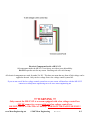
1
www.Mesa-Engineering.net
ME-LVCI v1.10
Low Voltage Screen Control Interface Module
A low voltage interface for use between Extron® MediaLink series
control panels and electric drop down screens to control the
Up, Down & Stop commands.
Works with the following Extron panels:
• MediaLink MLC 226 IP (page 1-1 – 1-4)
• MediaLink MLC 206 (page 2-1 – 2-6)
• MediaLink MLC 104 IP Plus* (page 3-1 – 3-5)
(*Extron IPV T RLY4 #60-545-03 also required)
www.Mesa-Engineering.net
© 2007 Mesa Engineering
Rev. A 01/07
0-1
Electrical Components Inside a ME-LVCI
All components inside the ME-LVCI are factory set with no user adjustability.
DO NOT open the unit for any reason. Breaking seal will void warranty.
All electrical components are rated for under 50v DC. This does not mean that any form of high voltage can be
applied to the unit. Only run low voltage from a low voltage control system box.
If you are not sure if the low voltage control system box on your screen will interface with the ME-LVCI
contact us at [email protected] or at www.mesa-engineering.net
!!! WARNING !!!
Only connect the ME-LVCI to a screen equipped with a low voltage control box.
NEVER connect to a screen with out a low voltage control box.
DO NOT connect to 110v/220v AC directly. FOR LOW VOLTAGE USE ONLY!
www.Mesa-Engineering.net
© 2007 Mesa Engineering
Rev. A 01/07
0-2
User Manual - Low Voltage Controller Interface (ME-LVCI v1.10)
Wiring Configuration Between Screen and Extron® MLC 226 IP Series
ME-LVCI to Screen Control Box (ie: DA-Lite Single Motor Low Voltage Control System)
1. Connect the RED wire to pin 3 of the Screen Control box (Labeled as UP on some controls).
2. Connect the BLACK wire to pin 2 of the Screen Control box (Labeled as DOWN on some controls).
3. Connect the WHITE (and/or bare shield) wire to pin 1 of the Screen Control box (Common).
ME-LVCI to Extron® MLC 226 Panel.
1. Connect the RED wire to 1 of Relay A.
2. Connect the BLACK wire to 3 of Relay B.
3. Connect the GREEN wire to 2 of Relay A.
4. Connect the WHITE wire to COMMON of Relay A.
5. Jumper COMMON of Relay A to COMMON of Relay B.
(All grounds/shields outputs on ME-LVCI on the “to extron” side are internally connected to WHITE,
can also be used to connect to COMMON instead of jumper)
www.Mesa-Engineering.net
© 2007 Mesa Engineering
Rev. A 01/07
1-1
User Manual - Low Voltage Controller Interface (ME-LVCI v1.10)
Configuration of Extron® Control Buttons
Button Arrangement (Configuration 1)
Buttons can be arranged in any order. The best and most practical locations are shown in the following
figure. With UP as the top button, DOWN as the bottom button and STOP as the center button.
Go to page 1-3 for software configuration.
Button Arrangement (Configuration 2)
The Up & Down buttons can also be controlled by the “Display” ON/OFF buttons. When you turn the
projector on the screen will drop down. When you turn the projector off the screen will rise. All to create a
“Professional” look.
Go to page 1-4 for software configuration.
NOTE To control with the above configuration, swap the BLACK (Down) wire with the GREEN (stop) wire. Do not connect
COMMON to the common of relay B. With this configuration only relay A 1, 2, & Common should be connected. This
frees up the remaining relays for other controls.
www.Mesa-Engineering.net
© 2007 Mesa Engineering
Rev. A 01/07
1-2
User Manual - Low Voltage Controller Interface (ME-LVCI v1.10)
Configuration of Extron® Global Configurator v2.2.0 for Button Configuration 1
Button Configuration 1 Overview
1. 1 Select the Front Panel tab.
2. 2 Select the button to be programmed.
3. 3 Name the button (to the right, Line 1:) *optional step, makes for quicker identification within software
4. 4 Under Button Operations select the Relay tab.
5. 5 Select relay to be used, operation of relay and pulse time. (see settings table below)
6. 6 Click on Press above the textbox to the right. (it will turn gray)
7. 7 Click the small green arrow to add the relay operation to the function of the button.
NOTE Once button is programmed a red triangle will appear in the upper left corner of that button.
Settings:
Button 1 (top) – UP: Relay 1, Pulse, 2.00 seconds.
Button 2 (middle) – STOP: Relay 2, Pulse, 2.00 seconds.
Button 3 (bottom) – DOWN: Relay 3, Pulse, 2.00 seconds.
www.Mesa-Engineering.net
© 2007 Mesa Engineering
Rev. A 01/07
1-3
User Manual - Low Voltage Controller Interface (ME-LVCI v1.10)
Configuration of Extron® Global Configurator v2.2.0 for Button Configuration 2
Button Configuration 2 Overview
1. 1 Select the Front Panel tab.
2. 2 Select the button to be programmed either Display On or OFF.
3. 3 Name the button (if it’s not already:) *optional step, makes for quicker identification within software
4. 4 Under Button Operations select the Relay tab.
5. 5 Select relay to be used, operation of relay and pulse time. (see settings table below)
6. 6 Click on Press above the textbox to the right. (it will turn gray)
7. 7 Click the small green arrow to add the relay operation to the function of the button.
NOTE Once button is programmed a red triangle will appear in the upper left corner of that button.
Settings:
Display ON – UP: Relay 1, Pulse, 2.00 seconds.
Display OFF – STOP: Relay 2, Pulse, 2.00 seconds.
www.Mesa-Engineering.net
© 2007 Mesa Engineering
Rev. A 01/07
1-4
User Manual - Low Voltage Controller Interface (ME-LVCI v1.10)
Wiring Configuration Between Screen and Extron® MLC 206 Series
ME-LVCI to Screen Control Box (ie: DA-Lite Single Motor Low Voltage Control System)
1. Connect the RED wire to pin 3 of the Screen Control box (Labeled as UP on some controls).
2. Connect the BLACK wire to pin 2 of the Screen Control box (Labeled as DOWN on some controls).
3. Connect the WHITE (and/or bare shield) wire to pin 1 of the Screen Control box (Common).
ME-LVCI to Extron® MLC 206.
1. Connect the RED wire to 1A of Relays.
2. Connect the BLACK wire to 2A of Relays.
3. GREEN wire not used.
4. Connect the WHITE wire to 1B of Relays.
5. Jumper WHITE to 2B of Relays.
(All grounds/shields outputs from the ME-LVCI on “To Extron” side are internally
connected to WHITE, can also be used to connect to COMMON
instead of jumper)
www.Mesa-Engineering.net
© 2007 Mesa Engineering
Rev. A 01/07
2-1
User Manual - Low Voltage Controller Interface (ME-LVCI v1.10)
Configuration of Extron® MLC 206 Control Buttons
Button Arrangement
Configuration 1
Buttons can be arranged in any order. The best and most practical locations are shown in the following
figure. With UP as the top button (button #3,) & DOWN as the bottom button (button #6)
Configuration 2
Buttons can also be attached to the Display Power. When the display is powered on the electric screen
will drop down. When the display is powered off the screen will rise up.
www.Mesa-Engineering.net
© 2007 Mesa Engineering
Rev. A 01/07
2-2
User Manual - Low Voltage Controller Interface (ME-LVCI v1.10)
Configuration of Extron® MediaLink Control Program v2.4
Button Configuration 1 Overview
(For UP Command)
1. 1 Select the Controller (MLC) Config. tab.
2. 2 Make sure the Switch is checked on 3.
3. 3 Check Rly 1 box
Button Configuration 1 Overview
(For DOWN Command)
4. 1 Select the Controller (MLC) Config. tab.
5. 2 Make sure the Switch is checked on 6.
6. 3 Check Rly 2 box
www.Mesa-Engineering.net
© 2007 Mesa Engineering
Rev. A 01/07
2-3
User Manual - Low Voltage Controller Interface (ME-LVCI v1.10)
Configuration of Extron® MediaLink Control Program v2.4
Button Configuration 1 Overview (cont.)
7. 1 Select the Relay & Misc. Options tab.
8. 2 Set Relay 1 Mode to the following settings.
• Tied to Btn: Input 3
• Momentary (set to 2 Sec)
• (NO) Open
9. 3 Set Relay 2 Mode to the following settings.
• Tied to Btn: Input 6
• Momentary (set to 2 Sec)
• (NO) Open
www.Mesa-Engineering.net
© 2007 Mesa Engineering
Rev. A 01/07
2-4
User Manual - Low Voltage Controller Interface (ME-LVCI v1.10)
Configuration of Extron® MediaLink Control Program v2.4
Button Configuration 2 Overview
(For UP Command)
1. 1 Select the Controller (MLC) Config. tab.
2. 2 Select ON from Display Power.
3. 3 Check Rly 1 box
Button Configuration 2 Overview
(For DOWN Command)
4. 1 Select the Controller (MLC) Config. tab.
5. 2 Select OFF from Display Power.
6. 3 Check Rly 2 box
www.Mesa-Engineering.net
© 2007 Mesa Engineering
Rev. A 01/07
2-5
User Manual - Low Voltage Controller Interface (ME-LVCI v1.10)
Configuration of Extron® MediaLink Control Program v2.4
Button Configuration 2 Overview (cont.)
7. 1 Select the Relay & Misc. Options tab.
8. 2 Set Relay 1 Mode to the following settings.
• Tied to Btn: DispPwr ON
• Momentary (set to 2 Sec)
• (NO) Open
9. 3 Set Relay 2 Mode to the following settings.
• Tied to Btn: DispPwr OFF
• Momentary (set to 2 Sec)
• (NO) Open
www.Mesa-Engineering.net
© 2007 Mesa Engineering
Rev. A 01/07
2-6
User Manual - Low Voltage Controller Interface (ME-LVCI v1.10)
Wiring Configuration Between Screen and Extron® MLC 104 IP PLUS Series
NOTE An Extron IPV T RLY4 (part #60-545-03) must be used to convert the MLC 104 IP PLUS digital I/O ports to NO/NC relays.
ME-LVCI to Screen Control Box (ie: DA-Lite Single Motor Low Voltage Control System)
1. Connect the RED wire to pin 3 of the Screen Control box (Labeled as UP on some controls).
2. Connect the BLACK wire to pin 2 of the Screen Control box (Labeled as DOWN on some controls).
3. Connect the WHITE (and/or bare shield) wire to pin 1 of the Screen Control box (Common).
ME-LVCI to Extron® IPA T RLY 4
1. Connect the RED wire to NO of Relay 1.
2. Connect the BLACK wire to NO of Relay 2.
3. GREEN wire not used.
4. Connect the WHITE wire to C of Relay 1.
5. Jumper C of Relay 1 to C of Relay 2.
(All grounds/shields outputs from the ME-LVCI on “To Extron” side
are internally connected to WHITE, can also be used to connect to COMMON
instead of jumper)
Connect Extron® 104 IP Plus to IPV T RLY 4
1. Connect the 12V OUT from the COMM LINK
to C on the IPA T RLY4 INPUTS.
2. Connect DIGITAL I/O 1 to 1 of the IPA T RLY4.
3. Connect DIGITAL I/O 2 to 2 of the IPA T RLY4.
www.Mesa-Engineering.net
© 2007 Mesa Engineering
Rev. A 01/07
3-1
User Manual - Low Voltage Controller Interface (ME-LVCI v1.10)
Configuration of Extron® MLC 104 IP PLUS Control Buttons
Button Arrangement (Configuration 1)
Buttons can be arranged in any order. The best and most practical locations are shown in the following
figure. With UP as the top button (3rd down,) & DOWN as the bottom button (4th down)
Go to page 3-4 for software configuration.
Button Arrangement (Configuration 2)
The Up & Down buttons can also be controlled by the “Display” ON/OFF buttons. When you turn the
projector on the screen will drop down. When you turn the projector off the screen will rise. This configuration
will create a “Professional” look for presentations.
Go to page 3-5 for software configuration.
www.Mesa-Engineering.net
© 2007 Mesa Engineering
Rev. A 01/07
3-2
User Manual - Low Voltage Controller Interface (ME-LVCI v1.10)
Configuration of Extron® Global Configurator v2.2.0
Setting Digital I/O Ports
1. 1 Select the Advanced Configuration tab.
2. 2 Change Digital I/O #1 to “Output”
3. 2 Change Digital I/O #2 to “Output”
www.Mesa-Engineering.net
© 2007 Mesa Engineering
Rev. A 01/07
3-3
User Manual - Low Voltage Controller Interface (ME-LVCI v1.10)
Configuration of Extron® Global Configurator v2.2.0 for Button Configuration 1
NOTE See page 3-3 for setting Digital I/O ports to output before continuing.
Button Configuration 1 Overview
1. 1 Select the Front Panel tab.
2. 2 Select the #3 button to be programmed.
3. 3 Name the button *optional step, makes for quicker identification within software
4. 4 Under Button Operations select the 5 Digital Output tab.
5. 6 Select Pulse of Digital Output #1, Set pulse time to 2.00 seconds
6. 7 Click the green add arrow.
7. For next button repeat setps #2-6, this time set #4 button to Digital Output #2
www.Mesa-Engineering.net
© 2007 Mesa Engineering
Rev. A 01/07
3-4
User Manual - Low Voltage Controller Interface (ME-LVCI v1.10)
Configuration of Extron® Global Configurator v2.2.0 for Button Configuration 2
NOTE See page 3-3 for setting Digital I/O ports to output before continuing.
Button Configuration 2 Overview
1. 1 Select the Front Panel tab.
2. 2 Select the ON button to be programmed.
3. 3 Name the button (if it’s not already:) *optional step, makes for quicker identification within software
4. 4 Under Button Operations select the 5 Digital Output tab.
5. 6 Select Pulse of Digital Output #1, Set pulse time to 2.00 seconds
6. 7 Click the green add arrow.
7. For next button repeat setps #2-6, this time set the OFF button to Digital Output #2
www.Mesa-Engineering.net
© 2007 Mesa Engineering
Rev. A 01/07
3-5