1
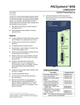
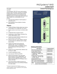
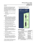
Important Product Information PACSystems* RX3i IC695CPU315-CN PACSystems* RX3i CPU GFK-2586Q May 2015 The PACSystems* RX3i CPU can be used to perform real time control of machines, processes, and material handling systems. The CPU communicates with the programmer and HMI devices via a serial port using SNP Slave protocol. It communicates with I/O and smart option modules over a dual backplane bus that provides: ▪ High-speed PCI backplane for fast throughput of new advanced I/O. ▪ Serial backplane for easy migration of existing Series 90*-30 I/O. Features ▪ ▪ ▪ ▪ ▪ ▪ ▪ ▪ ▪ ▪ ▪ ▪ ▪ ▪ Contains 20 Mbytes of battery-backed user memory and 20 Mbytes of non-volatile flash user memory. Provides access to bulk memory via reference table %W. Configurable data and program memory. Programming in Ladder Diagram, Structured Text, Function Block Diagram, and C. Refer to PACSystems RX7i & RX3i CPU Programmer’s Reference Manual, GFK-2950. Supports auto-located Symbolic Variables that can use any amount of user memory. Reference table sizes include 32Kbits for discrete %I and %Q and up to 32K words each for analog %AI and %AQ. Supports most Series 90-30 modules and expansion racks. For a list of supported I/O, Communications, Motion, and Intelligent modules, refer to the PACSystems RX3i System Manual, GFK-2314F or later. Supports up to 512 program blocks. Maximum size for a block is 128KB. CPU firmware may be upgraded in the field. CPU supports firmware upgrades of modules in its backplane. Two serial ports: an RS-485 serial port and an RS-232 serial port. Ethernet communications via the rack-based Ethernet Interface module (IC695ETM001). For details on Ethernet capabilities, refer to PACSystems RX7i & RX3i TCP/IP Ethernet Communications User Manual, GFK-2224. Time Synchronization to SNTP Time Server on Ethernet network when used with Ethernet Release 5.0 or later module. Compliant with EU RoHS Directive 2002/95/EC using the following exemptions identified in the Annex: 7(a), 7(c)-I, & 7(c)-III Ordering Information Catalog Number IC695CPU315 IC695ACC302 IC693ACC302 IC690RBT001 Description RX3i 1GHz Celeron M CPU with 20MB User Memory Smart Auxiliary Battery for Memory Retention Auxiliary Battery for Memory Retention Rechargeable Battery for Memory Retention Indicates a trademark of General Electric Company and/or its subsidiaries. All other trademarks are the property of their respective owners. Copyright © 2010-2015 General Electric Company. All Rights Reserved. * 2 PACSystems* RX3i CPU GFK-2586Q IC695CPU315-CN Specifications: CPU315 CPU Performance For CPU315 performance data, refer to Appendix A of the PACSystems CPU Reference Manual, GFK-2222V or later. Battery: Memory retention For battery selection, installation and estimated life, refer to the PACSystems RX3i and RX7i Battery Manual, GFK-2741 Program storage Up to 20 MB of battery-backed RAM 20 MB of non-volatile flash user memory Power requirements +3.3 Vdc: 1.0 Amps nominal +5 Vdc: 1.2 Amps nominal Operating Temperature 0 to 60°C (32°F to 140°F) Floating point Yes Time of Day Clock accuracy Maximum drift of 2 seconds per day Elapsed Time Clock (internal 0.01% maximum timing) accuracy Embedded communications RS-232, RS-485 Serial Protocols supported Modbus RTU Slave, SNP, Serial I/O Backplane Dual backplane bus support: RX3i PCI and high-speed serial bus PCI compatibility System designed to be electrically compliant with PCI 2.2 standard Program blocks Up to 512 program blocks. Maximum size for a block is 128KB. Memory %I and %Q: 32Kbits for discrete %AI and %AQ: configurable up to 32Kwords %W: configurable up to the maximum available user RAM Symbolic: configurable up to 20 Mbytes For product standards, general operating specifications, and installation requirements, refer to PACSystems RX3i System Manual, GFK-2314. PACSystems* RX3i CPU IC695CPU315-CN 3 GFK-2586Q Installation Location This product is intended for use with the RX3i system. Its components are considered open equipment (having live electrical parts that may be accessible to users) and must be installed in an ultimate enclosure that is manufactured to provide safety. At a minimum, the enclosure shall provide a degree of protection against solid objects as small as 12mm (fingers, for example). This equates to a NEMA/UL Type 1 enclosure or an IEC60529 IP20 rating providing at least a pollution degree 2 environment. For details about installing RX3i rack systems, refer to PACSystems RX3i System Manual, GFK-2314. Installation in Hazardous Areas The following information is for products bearing the UL marking for Hazardous Areas or ATEX marking for explosive atmospheres: CLASS 1 DIVISION 2 GROUPS ABCD This equipment is an open-type device and is meant to be installed in an enclosure suitable for the environment that is only accessible with the use of a tool. Suitable for use in Class I, Division 2, Groups A, B, C and D Hazardous Locations, or nonhazardous locations only. Warning – EXPLOSION HAZARD - SUBSTITUTION OF COMPONENTS MAY IMPAIR SUITABILITY FOR CLASS I, DIVISION 2. Warning – WHEN IN HAZARDOUS LOCATIONS, TURN OFF POWER BEFORE REPLACING OR WIRING MODULES. ATEX Zone 2 This module must be mounted in an enclosure certified in accordance with EN60079-15 for use in Zone 2, Group IIC and rated IP54. The enclosure shall only be able to be opened with the use of a tool. 4 PACSystems* RX3i CPU GFK-2586Q IC695CPU315-CN Release History Catalog Number Firmware Revision Date Comments IC695CPU315-CN 8.50 IC695CPU315-CM 8.15 May 2015 May 2014 IC695CPU315-CL 8.05 Feb 2014 IC695CPU315-CK 7.80 IC695CPU315-CJ 7.75 Sep 2013 May 2013 IC695CPU315-CH 7.70 IC695CPU315-CG 7.18 IC695CPU315-CF 7.15 Jul 2012 IC695CPU315-CE 7.14 Jun 2012 IC695CPU315-CE 7.13 IC695CPU315-CD 7.00 IC695CPU315-BD 7.00 IC695CPU315-BC 6.71 IC695CPU315-BB 6.70 IC695CPU315-AB 6.70 Apr 2012 Oct 2011 Jul 2011 May 2011 Mar 2011 Dec 2010 Add support for HART® Pass Through feature. Refer to PACSystems RX3i HART Pass Through User Manual, GFK-2929. Adds support for IC695RMX228 128 MB Reflective Memory Module with Single Mode Transceiver. Adds ability to read reflective memory status bits for IC695CMX128, IC695RMX128, and IC695RMX228 (reflective memory modules). Resolves issue of Serial I/O Read Bytes COMMREQ (4402) always returning error code 100Dh in the event of an error, regardless of the error. Adds support for the new IC695ECM850 (IEC 61850 Ethernet Communication Module), which operates as an IEC 61850 Client and provides connectivity to IEC 61850 Server devices. Resolves issue of CPU halting when the inner FOR_LOOP's Start is greater than End input in a nested FOR_LOOP. Adds remote PROFINET IO to PACSystems RX3i Hot Standby Redundancy systems. Resolves issue with LREAL operands within complex relational expressions. Corrects an issue in versions 7.15 – 7.70 that required setting OEM lock in Enhanced Security in order to preserve the OEM lock through a power cycle. Adds support for RX3i CMX/RMX modules version –CG (hardware version -Cx with firmware version 2.00 and later). Adds support for the following new modules: IC694MDL758, IC695CNM001 and IC694PSM001. Adds the ability to monitor a new interface between the CPU and the CMX/RMX Memory Xchange modules (CMX/RMX Memory Xchange module firmware 1.06 and later). In the rare occasion the CMX/RMX Memory Xchange module detects a failure in a read operation, the CMX/RMX Memory Xchange module will indicate the last read is invalid. The CPU will then retry the previous read operation. Adds native support for the new Power Sync and Measurement module (IC694PSM001) and resolves several issues. Also introduces new features to augment security in the CPU firmware and Proficy Machine Edition software. For details, see New Features and Enhancements and Problems Resolved in Release 7.15 in PACSystems RX3i CPU IC695CPU315 IPI, GFK-2586L. Corrects an issue where executing a Run Mode Store, displaying the Proficy Machine Edition Show Status window, or requesting data using the PACSAnalyzer tool could cause discrete output modules to unexpectedly change state momentarily (up to one PLC scan). Corrects issues with Logic Write to Flash (Service Request 57). IC695CPU315-AA 6.02 ® Feb 2013 Nov 2012 Jul 2010 Hardware revision to correct an issue with the RS-485 (COM2) serial port. Adds support for the PROFINET Controller module, IC695PNC001. Corrects the behavior of the Logic Driven Read/Write to Flash service requests, SVC_REQ56 and SVC_REQ 57. Implements a hardware design update that improves the noise immunity of the CPU module during power up from flash operations. Introduces support for new modules, enhancements to the Modbus RTU protocol, improved Run signal handling in the expansion rack and other improvements. Resolves several problems found in earlier releases. Initial release. For details, see PACSystems RX3i CPU IC695CPU315 IPI, GFK-2586. HART® is a registered trademark of the HART Communication Foundation of Austin, Texas USA. Any use of the term HART hereafter in this document, or any document referenced by this document, implies the registered trademark. PACSystems* RX3i CPU 5 IC695CPU315-CN GFK-2586Q Important Product Information for this Release Field Upgrade Upgrade Kit: 82A1715-MS10-000-A13 When upgrading for HART Pass Through functionality, the supporting RX3i Analog I/O modules must contain HARTcompatible firmware. If used for HART Pass Through, the PROFINET Controller (PNC001) and PROFINET Scanner (PNS001 or CEP001) must also contain HART-compatible firmware (see below). New Features and Enhancements Subject Description Supports the HART Pass Through Feature HART-capable RX3i Analog I/O modules can communicate HART data via this CPU to compatible asset management tools. Refer to the PACSystems HART Pass Through User Manual, GFK-2929 for more details. Problems Resolved by this Revision Subject None ID Code Description This release provides feature enhancement only. 6 PACSystems* RX3i CPU GFK-2586Q IC695CPU315-CN Functional Compatibility The following are required to use the features introduced in the most recent CPU release: Subject Minimum Version Required Programmer Version Requirements PME 8.50 SIM 2 or later. Supports the HART Pass Through Feature HART-capable RX3i Analog I/O modules can communicate HART data via this CPU to compatible asset management tools. Refer to the PACSystems HART Pass Through User Manual, GFK-2929 for more details. The following RX3i analog modules support HART: IC695ALG626 1 IC695ALG628 IC695ALG728 If used for HART Pass Through, the supporting RX3i PROFINET Controller (PNC001) and PROFINET Scanner (PNS001 or CEP001) must also contain HART-compatible firmware: IC695PNC001 Firmware Release 2.20 IC695PNS001 Firmware Release 2.30 IC695CEP001 Firmware Release 2.30. C Toolkit Compatibility The C Toolkit for PACSystems is distributed with Proficy Machine Edition Logic Developer. Updates can be downloaded from http://www.ge-ip.com/support. C Toolkit Release 5.00 Build 16C1 or later is required when the PACSystems CPU contains firmware Release 5.00 or later. C Toolkit release 5.50 or later is required for use with the LREAL data type. Note: C blocks that were built using C Toolkit versions earlier than 5.00 Build 16C1 must be recompiled using a newer toolkit version for use with CPU firmware release 5.00 or higher. Note: The Series 90 Toolkit (IC641SWP709/719) is not compatible with PACSystems. RS-485 Port Compatibility When the CPU is first powered on, the RS-485 port (COM 2) powers up with the transmitter enabled. The transmitter is placed into a high-impedance state once the CPU OK LED is illuminated. Since that takes a finite amount of time, this could be an issue if the COM 2 port is being used in multi-drop communications, and other devices share the same cable via wiredOR connections. If one of those devices is actively communicating when the CPU is powered up, there is a potential for those communications to be disrupted until the CPU puts the RS-485 port into high-impedance state. Backplanes, power supplies and I/O modules For lists of compatible backplanes, power supplies and I/O modules, refer to the PACSystems RX3i System Manual, GFK-2314F or later. Series 90-30 Expansion Rack Compatibility Series 90-30 expansion racks, both local and remote, are supported by the PACSystems RX3i System. PACSystems RX3i CPUs must be located in an RXi Universal Backplane. They do not operate in a Series 90-30 Rack. Series 90-30 Main Rack Compatibility Series 90-30 Main Racks cannot be used in a PACSystems RX3i system. Series 90-30 CPUs do not operate in PACSystems RX3i Racks. Recommended IC200ALG240 revision When a VersaMax* system Genius* Network Interface Unit (IC200GBI001) operates with a Genius Bus Controller located in a PACSystems RX3i, and the VersaMax system contains an IC200ALG240 Analog Input Module, it is recommended to update the IC200ALG240 firmware to Revision 1.20 or later using upgrade kit 44A752313-G02 or later. Upgrade kits are available at http://www.ge-ip.com/support. 1 If used, IC695ALG628 must be installed in the RX3i CPU Rack. At time of publication, it is not supported by PROFINET scanners IC695PNS001 or IC695CEP001. Refer to IPIs for IC695PN001 or IC695CEP001 for future updates. PACSystems* RX3i CPU 7 IC695CPU315-CN GFK-2586Q Restrictions and Open Issues Restrictions and Open Issue Restriction/Open Issue Description Missing Addition of IOC event when ECM850 module restarts due to reset pushbutton or SVC_REQ 24 When ECM850 module RESET is triggered using SVC_REQ 24 or Reset pushbutton, CPU does not report Addition of IOC fault message in Controller fault table after successful reset of module. PMM335 loss is occasionally detected on power down of the CPU. (Module is not lost on power up.) The PMM335 PACMotion Multi-axis Motion Controller monitors power loss, independently of the CPU. The CPU is fast enough that it can occasionally detect and log the loss of the PMM335 just before the CPU itself powers down. No corrective action is required. This situation can be verified in two ways: (1) by inspecting the timestamp in the loss-of-module report one can correlate it with the power-down event, and (2) by performing a PME Show Status Details report to see that the PMM335 is present after power up. Rare condition of CPU lights out during power cycles In rare instances during multiple rapid power cycles, the CPU will fail to power up. If this occurs, the CPU should recover with the next power cycle. The Ethernet module fails to exchange EGD properly during power cycling Very rarely, after experiencing multiple rapid power cycles, the CPU may fail to establish communication with one or more modules in the backplane at power up. When this occurs, several pairs of a Loss of, or missing option module and Reset of option module faults will be logged in the controller fault table. If the module is an ETM, an event 30H is recorded in its station manager event log. To recover from this issue, cycle power again. Loss of power supplies after firmware update A Loss of Power Supplies after firmware update may occur. This does not happen with all firmware updates and will NOT occur if the system is power cycled after the firmware upgrade has completed. The faults displayed when this issue occurs are as follows: Loss of, or missing option module Error Code: 36 Group: 4 Action: 3:Fatal Task Num: 9 Fault Extra Data: 01 58 02 4f 80 08 0a 07 00 00 00 00 00 00 00 00 00 00 00 00 00 00 00 00 Battery installation. When installing a new battery, if there currently is no battery installed, the battery must be installed while the CPU has power. Failing to follow this procedure could result in the CPU not powering up. If a battery is installed while power is off (and there was no battery previously installed), and the CPU fails to power up, remove the battery, power cycle the CPU and then install the battery. Hot swapping some analog modules slowly may result in modules not being recognized. Occasionally during a hot insertion (hot swap) of RX3i Non-Isolated Analog Input Modules, input channels may take up to 2 seconds to reflect actual input values after the module OK bit is enabled in the module status word. This has only been seen when the hot insertion has been done slowly (i.e. approximately 1.5 seconds to insert the module). Refer to PACSystems RX3i System Manual, GFK-2314F or later for updated hot-swap information. Ethernet disconnect during Word-for-Word change. If the Ethernet connection is broken during a word-for-word change, the programmer may not allow a subsequent word-for-word change after reconnecting due to the fact that it thinks another programmer is currently attached. If this occurs, you should go offline and then back online again. Simultaneous Clears, Loads and Stores not supported. PACSystems CPUs do not support multiple programmers changing CPU contents at the same time. The programming software may generate an error during the operation. Simultaneous loads from a single CPU are allowed. Hardware configuration Not Equal after changing target name. If you store a hardware configuration to flash that sets Logic/Config Power-up Source to Always Flash or Conditional Flash and then change the name of the target in the programming software, the hardware configuration will go Not Equal and will not verify as equal. 8 PACSystems* RX3i CPU GFK-2586Q IC695CPU315-CN Restrictions and Open Issue Restriction/Open Issue Description Controller and IO Fault Tables may need to be cleared twice to clear faulted state. Both Controller and IO fault tables may need to be cleared to take the CPU out of Stop/Fault mode. If one of the tables contains a recurring fault, the order in which the tables are cleared may be significant. If the CPU is still in Stop/Fault mode after both tables are cleared, try clearing the fault tables again. Setting Force On/Off by storing initial value. Once a force on or force off has been stored to the controller, you cannot switch from force on to force off or vice-versa by downloading initial values. To turn the force on or off, download the project. Number of active programs returned as zero. The SNP request Return Controller Type and ID currently returns the number of active programs as zero. Serial I/O fails at 115K during heavy interrupt load. Rare data corruption errors have been seen on serial communications when running at 115K under heavy interrupt load on the controller. Under heavy load applications, users should restrict serial communications to 57K or lower. Multi-drop serial communications interrupted by CPU315/32 power cycle Communications can be disrupted when two EIA485 ports (COM 2) are wired together/multidropped using a two wire connection (wired or) and either CPU (IC695CPU320 or IC695CPU315) is powered on while the other CPU is communicating. SNP ID not always provided. Unlike the Series 90-30, the RX3i CPU’s SNP ID does not appear in the Machine Edition programmer Show Status display. Service Request 11 will always return zeros. Second programmer can change logic while in Test & Edit mode. While currently active in a Test and Edit session using Machine Edition on one PC, Machine Edition running on another PC is not prevented from storing new logic to the controller. Must have logic if powering up from flash. If the application will configure the CPU to retrieve the contents of flash memory at power-up, be sure to include logic along with hardware configuration when saving to flash memory. CPU may not detect lowbattery condition An IC693ACC302 battery with very low capacity may still have a terminal voltage high enough to report that it is a good battery. In this case, when the battery starts supplying the memory power (battery backup), the battery voltage quickly drops to unacceptable levels, with little warning to the user before failure. To insure against data loss, users should replace batteries in accordance with the guidelines provided in the PACSystems RX7i & RX3i CPU Reference Manual, GFK-2222. Additionally, users could save logic and hardware configuration to flash. Two Loss of Module faults for Universal Analog module. Occasionally, the hot removal of the Universal Analog Input Module (IC695ALG600) results in two Loss of I/O Module faults instead of one. Power up of Series 90-30 HSC module may take as long as 20 seconds. As power is applied to a 90-30 High-Speed Counter, the Module Ready bit in the status bits returned each sweep from the module may not be set for as long as 20 seconds after the first controller sweep, even though there is no Loss of Module indication. I/O data exchanged with the module is not meaningful until this bit is set by the module. Refer to the Series 90-30 High Speed Counter User’s Manual, GFK-0293C, Section 4.7. Informational fault at power up. Intermittently during power-up, an Informational non-critical CPU software fault may be generated with fault extra data of 01 91 01 D6. This fault will have no effect on the normal operation of the controller. But, if the hardware watchdog timer expires after this fault and before power has been cycled again, then the outputs of I/O modules may hold their last state, rather than defaulting to zero. Extended memory types for IO triggers. %R, %W and %M cannot be used as IO triggers. Possible Machine Edition inability to connect. Infrequently, an attempt to connect a programmer to a controller via Ethernet will be unsuccessful. The normal connection retry dialog will not be displayed. Rebooting the computer that is running the programmer will resolve the behavior. SNP Update Datagram message. If an Update Datagram message requests 6 or less bits or bytes of data, the controller will return a Completion Ack message without Text Buffer. The protocol specifies that the returned data will be in the Completion Ack message, but it may not be. GBC30 may not resume operation after power cycle. In rare instances, a GBC30 in an expansion rack may not resume normal operation after a power cycle of either the expansion rack or the main rack. To restore GBC operation, power cycle the rack again. Configuration of third-party modules. Do not specify a length of 0 in the configuration of a third-party module. The module will not work properly in the system. PACSystems* RX3i CPU 9 IC695CPU315-CN GFK-2586Q Restrictions and Open Issue Restriction/Open Issue Description Power supply status after CPU firmware update. The controller will report a Loss of or Missing Option Module fault for the IC695PSD140 RX3i power supply following an update of CPU firmware. Also, the slot will appear empty in the programmer’s online status detail view. The power supply continues to operate normally. Power cycle to restore normal status reporting. Power supply status after power cycling. Rarely, turning a power supply on or off may not result in an Add or Loss fault. Also, the slot will appear empty in the programmer’s online status detail view. The power supply continues to operate normally. Power cycle to restore normal status reporting. Don’t use multiple targets. In a system in which the hardware configuration is stored from one target and logic is stored from a different target, powering-up from flash will not work. The observed behavior is that, following a power up from flash, Machine Edition reports hardware configuration and logic Not Equal. Missing Loss of Terminal Block fault. The IC695ALG600/608/616 analog input modules do not produce a Loss of Terminal Block fault when hardware configuration is stored or the module is hot-inserted, and the terminal block is not locked into place. Sequence Store failure. When downloading projects with very large hardware configuration or which use large amounts of user memory, it is possible to encounter a controller Sequence Store Failure error when writing the project to flash. To work around this error, either or both of the following actions may be helpful: 1. Perform an explicit clear of flash prior to performing the write. 2. Increase the operation timeout used by Machine Edition prior to performing the write. This is done by expanding the Additional Configuration in the Inspector window for the target controller, and adjusting the Request Timeout. The timeout may need to be increased to as much as 60,000 msec, depending on the amount of memory used and the condition of the flash memory. IC695ALG600 Lead Resistance Compensation setting. A configuration store operation will fail if a channel is configured for 3-wire RTD and Lead Resistance Compensation is set to Disabled. A Loss of Module fault will be logged in the I/O Fault table at the end of the store operation. To recover the lost module, the configuration must be changed to enable Lead Resistance Compensation and module must be power cycled. WinLoader may stop operating. On computers running Windows 2000 and using some versions of Symantec Antivirus protection, WinLoader will lock up if used in advanced mode. Recovery requires cycling the computer's power. Logic and HWC Not Equal after power cycle. If the Hardware Configuration from Target 1, with Logic/Configuration Power-up Source and Data Source both set to Always from Flash, is stored in Flash, then Logic and Hardware Config from Target 2, with Logic/Configuration Power-up Source both set to Always from RAM, are stored to RAM and there is a good battery, then when power is cycled the programmer may show that Logic and Hardware Config are not equal. The remedy is to clear Flash and re-store the Logic and Hardware Config from Target 2. WinLoader does not detect PC COM port in use when upgrading PACSystems CPU. WinLoader does not detect if a PC's COM port is in use when attempting to connect to a PACSystems CPU to perform a firmware upgrade. If the port is already in use it displays the status trying to connect followed by waiting for target. To proceed with the upgrade, press the abort button and disconnect the other application that is using the COM port. CPU315 user application and values cleared after power cycle. Under rare circumstances during multiple rapid power cycles the CPU315 will power up with the user application and data in RAM cleared. There will be a Corrupted user memory fault in the controller fault table (Group 130, Error code 1). This will not occur if the user application and data are loaded from flash on power-up (Always Flash or Conditional Flash) WinLoader does not display error when it can't connect serially with PACS CPU. WinLoader does not display an error message if it cannot connect to the PACS CPU when attempting to connect to a PACSystems CPU to perform a firmware upgrade. This occurs if the cable is physically not connected to the CPU or if the CPU's serial port is not configured for the same baud as WinLoader. In this case Winloader displays the status trying to connect followed by waiting for target. To proceed with the upgrade, press the abort button and correct the cable or baud rate setting. 10 PACSystems* RX3i CPU GFK-2586Q IC695CPU315-CN Operational Notes Subject Description Firmware upgrades using Slot 1 Firmware upgrades for modules in Slot 1 will only work for CPUs. Modules other than the CPU need to be in Slot 2 or higher to perform a firmware upgrade. Multiple calls to SVC_REQ 57 in a single sweep may cause CPU watchdog timeouts Multiple calls to SVC_REQ 57 (Logic Driven Write to Nonvolatile Storage) could result in the CPU tripping the watchdog timer and going to STOP-HALT mode. The number of calls to SVC_REQ 57 that can be made requires consideration of many variables, what the software watchdog timeout value is, how much data is being written, how long the sweep is, age of nonvolatile storage (flash), etc. If the application attempts to write to flash too frequently, the CPU could experience a watchdog timeout while waiting for a preceding write operation to complete. The Logic Driven Read/Write to Flash service requests are not intended for high frequency use. GE Intelligent Platforms recommends limiting the number of calls to SVC_REQ 57 to one call per sweep to avoid a potential watchdog timeout and the resulting transition to StopHalt. Prior to release 6.70 for the RX3i, the Modbus RTU slave protocol would return an Invalid Function Code error response (1) upon receipt of a request with an invalid or undefined function code. Starting with release 6.70, the Modbus RTU slave ignores requests with an invalid or undefined function code, and no response is sent. Error response 1 is no longer returned for Modbus RTU requests with invalid or undefined function codes. RUN LED is not illuminated on the Series 90-30 power supply for an RX3i remote/expansion rack with input modules only (releases earlier than 6.70). Undefined symbols in C blocks For firmware version 6.70 and later, the RUN LED for a remote/expansion rack reflects the current IO enable/disable state (even when there are no output modules in the expansion rack). The RUN LED for a remote/expansion rack with only input modules works as follows for all versions prior to version 6.70: When a remote or expansion baseplate is used with the RX3i, the RUN LED on the Series 90-30 power supply for that baseplate is illuminated when the system is in Run mode only if the rack contains at least one output module. If the rack contains input modules only, the RUN LED is not illuminated. This is due to the way input modules are managed in the PACSystems design and does not indicate an error. If an attempt is made to download a C block containing undefined symbols, the download will fail. Machine Edition will display the following message in the Feedback Zone: Error 8097: Controller Error – Controller aborted the request [0x05][0xFF] Prior to Release 5.00, C blocks containing undefined symbols could be successfully downloaded, but if they were executed the CPU would transition to Stop/Halt mode. For details, see C Toolkit Compatibility. Length of serial I/O buffer The Set Up Input Buffer Function always allocates a buffer containing 2049 bytes. This is one byte more than previous PACSystems releases. Changing IP address of Ethernet interface while connected Storing a hardware configuration with a new IP address to the RX3i while connected via Ethernet will succeed, then immediately disconnect because the RX3i is now using a different IP address than the Programmer. You must enter a new IP address in the Target Properties in the Machine Edition Inspector window before reconnecting. Duplicate station address for Modbus will conflict with other nodes The default serial protocol for the RX3i is Modbus RTU. The default Station Address is 1. If the RX3i is added to a multi-drop network, care must be taken that the RX3i is configured with a unique Station Address. Nodes with duplicate Station Addresses on the same network will not work correctly. Timer operation Care should be taken when timers (ONDTR, TMR, and OFDTR) are used in program blocks that are NOT called every sweep. The timers accumulate time across calls to the sub-block unless they are reset. This means that they function like timers operating in a program with a much slower sweep than the timers in the main program block. For program blocks that are inactive for large periods of time, the timers should be programmed in such a manner as to account for this catch up feature. Related to this are timers that are skipped because of the use of the JUMP instruction. Timers that are skipped will NOT catch up and will therefore not accumulate time in the same manner as if they were executed every sweep. Constant sweep Constant Sweep time, when used, should be set at least 10 ms greater than the normal sweep time to avoid over-sweep conditions when monitoring or performing on-line changes with the programmer. Window completion faults will occur if the constant sweep setting is not high enough. PACSystems* RX3i CPU 11 IC695CPU315-CN GFK-2586Q Subject Description Large number of COMMREQs sent to module in one sweep causes faults A large number of COMMREQs (typically greater than 8) sent to a given board in the same sweep may cause Module Software faults to be logged in the RX3i fault table. The fault group is MOD_OTHR_SOFTWR (16t, 10h) and the error code is COMMREQ_MB_FULL_START (2). When this occurs, the FT output of the function block will also be set. To prevent this situation, COMMREQs issued to a given board should be spread across multiple sweeps so that only a limited number (typically 8 or less) of COMMREQs are sent to a given board in each sweep. In addition, the FT output parameter should be checked for errors. If the FT output is set (meaning an error has been detected), the COMM_REQ could be re-issued by the application logic. C Block standard math functions do not set errno In C Blocks, standard math functions (e.g. sqrt, pow, asin, acos) do not set errno to the correct value and do not return the correct value if an invalid input is provided. Upgrading firmware Upgrading the CPU firmware with the WinLoader utility may fail when multiple IO modules are in the main rack, due to the time it takes to power cycle the rack system. If the upgrade process fails, move the CPU to a rack without IO modules and restart the upgrade process. Winloader initial connect baud rate is fixed at 19200 baud. Note that the firmware download will occur at 115.2K baud by default. Note that if you have Hyperterm open on a port, and then try to use Winloader on the same port, Winloader will often say Waiting for Target until the hyperterm session is closed. Hot swap Hot Swap of power supplies or CPUs is not supported. Serial port configuration COMMREQs With the following combination of circumstances, it is possible to render serial communications with the CPU impossible: User configuration disables the Run/Stop switch User configures the power up mode to Run or Last Logic is stored in FLASH and user configures CPU to load from FLASH on power-up User application issues COMMREQs that set the protocol on both of the serial ports to something that does not permit communications to the Machine Edition programmer. Incorrect COMMREQ status for invalid program name The program name for PACSystems is always LDPROG1. When another program name is used in a COMM_REQ accessing %L memory, an Invalid Block Name (05D5) error is generated. FANUC I/O Master and Slave operation Scan sets on the master do not work properly for the first operation of the scan set after entering RUN mode. They do work properly for subsequent scans. After downloading a new hardware configuration and logic, a power cycle may be required to resume FANUC I/O operation. Use controllers of similar performance in FANUC I/O networks. If a master or slave is located in an RX3i system, the other controllers should be RX3i or Series 90-30 CPU374. Repeated power up/down cycles of an expansion rack containing FANUC I/O slaves may result in failure of the slaves’ operation, with the RDY LED off. Lost count at power up for Serial IO Processor The serial IO Processor (IC693APU305) will lose the first count after every power up or every time the module receives a configuration. COMMREQ status words declared in bit memory types must be byte-aligned. In previous releases, the CPU allowed configuration of COMMREQ Status Words in bit memory types on a non-byte-aligned boundary. Even though the given reference was not bytealigned, the firmware would adjust it the next-lowest byte boundary before updating status bits, overwriting the bits between the alignment boundary and specified location. To ensure that the application operates as expected, release 3.50 requires configuration of COMMREQ Status Words in bit memory types to be byte-aligned. For example if the user specified status bit location of %I3, the CPU aligns the status bit location at %I1. Release 3.50 firmware requires the user to specify the appropriate aligned address (%I1) to ensure that the utilized location is appropriate for their application. Note that the actual reference location utilized is not changed, but now is explicitly stated for the user. 12 PACSystems* RX3i CPU GFK-2586Q IC695CPU315-CN Subject Description STOP and RUN mode transition priority The PACSystems CPU receives requests to change between STOP and RUN mode from many different sources. These include (but are not limited to) Proficy Machine Edition, HMIs, the user application, and the RUN/STOP switch. Since there are many potential sources for a mode change request, it is possible to receive a new mode change request while another is already in progress. When this occurs, the CPU evaluates the priority of the new mode change request with the mode change that is in progress. If the new mode change request has an equal or higher priority than the one already in progress, the CPU transitions to the new mode instead of the one in progress. If, however, the new mode change request has a lower priority than the one in progress, the new mode request is discarded and the CPU completes the mode change that is in progress. The sweep mode priorities are (listed from highest to lowest priority): STOP HALT, STOP FAULT, STOP, and RUN. (Note: The IO ENABLED/DISABLED state is not part of the mode priority evaluation.) For example, a CPU is in RUN IO ENABLED mode and a Service Request 13 function block is executed to place the CPU into STOP IO DISABLED mode. Before the transition to STOP IO DISABLED is completed, the RUN/STOP switch is changed from RUN IO ENABLED to RUN IO DISABLED. In this case, the CPU ignores the new request from the RUN/STOP switch to go to RUN IO DISABLED mode because it is already processing a request to go to STOP IO DISABLED mode and STOP mode has a higher priority than RUN mode. Suspend IO function block does not suspend EGD In a Series 90-70 the SUSPEND_IO function block suspends EGD in addition to IO Scan. In PACSystems controllers the SUSPEND IO suspends only the IO Scan. Additional Information For additional information, please refer to the manuals listed below. Manuals can be downloaded from the support website, http://support.ge-ip.com. PACSystems RX7i & RX3i CPU Reference Manual PACSystems RX7i & RX3i CPU Programmer’s Reference Manual C Programmer’s Toolkit for PACSystems PACSystems RX3i System Manual PACSystems RX7i & RX3i TCP/IP Ethernet Communications User Manual PACSystems TCP/IP Ethernet Communications Station Manager User Manual PACSystems RXi, RX3i, and RX7i Controller Secure Deployment Guide PACSystems RX3i and RX7i Battery and Energy Pack Manual PACSystems RX3i HART Pass Through User Manual GFK-2222 GFK-2950 GFK-2259 GFK-2314 GFK-2224 GFK-2225 GFK-2830 GFK-2741 GFK-2929