1
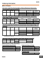
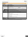
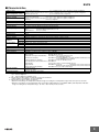
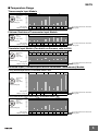
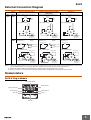
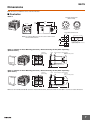
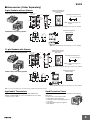
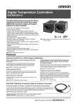
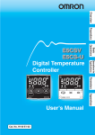
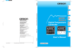
Temperature Controllers E5CS CSM_E5CS_DS_E_5_1 Simple Functions in DIN 48 × 48 mm-size Plug-in Temperature Controllers • Easy setting using DIP switch. • Models with two alarms added to Series, ideal for applications requiring alarms. • Universal-input (thermocouple/platinum resistance thermometer) models also available. • Clearly visible digital display with character height of 13.5 mm. • RoHS compliant. Refer to Safety Precautions for All Temperature Controllers. Refer to E5CS/E5CSV Operation for operating procedures. Model Number Structure ■ Model Number Legend Plug-in Models E5CS-@@@@U-W 1 2 3 4 5 6 3 1. Control Outputs R: Relay Q: Voltage for driving SSR 2. Alarm Outputs Blank: No alarm 1: 1 alarm 2: 2 alarms 3. Input KJ: Thermocouple P: Platinum resistance thermometer G: Thermistor T: Thermocouple/platinum resistance thermometer (universal-input) 4. Power Supply Voltage Blank: 100 to 240 VAC D: 24 VAC/VDC 5. Terminal Shape U: Plug-in 6. Case Color W: Light gray Note: A functional explanation is provided here for illustration, but models are not necessarily available for all possible combinations. Refer to Ordering Information when ordering. Examples • Relay control output, without alarm, thermocouple input, plug-in construction, light gray case: E5CS-RKJU-W • Relay control output, one alarm output, platinum resistance thermometer input, plug-in construction, light gray case: E5CS-R1PU-W 1 E5CS Ordering Information ■ List of Models Case Color: Light Gray, Thermocouple or Platinum Resistance Thermometer, Power Supply Voltage: 100 to 240 VAC Size E5CS-U 48 × 48 mm Type Plug-in Control modes ON/OFF or PID Alarms 0 1 Outputs Model with thermocouple Model with platinum resistance thermometer Relay E5CS-RKJU-W E5CS-RPU-W Voltage (for driving SSR) E5CS-QKJU-W E5CS-QPU-W Relay E5CS-R1KJU-W E5CS-R1PU-W Voltage (for driving SSR) E5CS-Q1KJU-W E5CS-Q1PU-W Case Color: Light Gray, Thermocouple or Platinum Resistance Thermometer, Power Supply Voltage: 24 VAC/VDC Size E5CS-U 48 × 48 mm Type Plug-in Control modes ON/OFF or PID Alarms 0 1 Outputs Model with thermocouple Model with platinum resistance thermometer Relay E5CS-RKJDU-W E5CS-RPDU-W Voltage (for driving SSR) E5CS-QKJDU-W --- Relay E5CS-R1KJDU-W E5CS-R1PDU-W Voltage (for driving SSR) E5CS-Q1KJDU-W --- Case Color: Light Gray, Thermistor or Universal-input, Power Supply Voltage: 100 to 240 VAC Size E5CS-U 48 × 48 mm Type Plug-in Control modes ON/OFF or PID Alarms 0 1 2 (See note.) Outputs Model with thermistor Model with universalinput (thermocouple and platinum resistance thermometer) Relay E5CS-RGU-W E5CS-RTU-W Voltage (for driving SSR) E5CS-QGU-W E5CS-QTU-W Relay E5CS-R1GU-W E5CS-R1TU-W Voltage (for driving SSR) E5CS-Q1GU-W E5CS-Q1TU-W Relay --- E5CS-R2TU-W Voltage (for driving SSR) E5CS-Q2TU-W Note: There is no alarm output 2 mode switch. The default setting for alarm output 2 is for the upper limit alarm mode. To change the setting, change the alarm type for alarm output 2 in initial setting level 5. For details, refer to the “E5CSV/E5CS-U Digital Temperature Controller User’s Manual” (Cat. No. H140-E1-01). Case Color: Light Gray, Thermistor, Power Supply Voltage: 24 VAC/VDC Size E5CS-U 48 × 48 mm Type Plug-in Control modes ON/OFF or PID Alarms 0 Outputs Relay 1 Model with thermistor E5CS-RGDU-W E5CS-R1GDU-W ■ Accessories (Order Separately) Socket without Alarm (8 Pins) Type Socket with Alarm (11 Pins) Model Type Model Front Connecting Socket P2CF-08 Front Connecting Socket P2CF-11 Back Connecting Socket (flush mounting) P3G-08 Back Connecting Socket (flush mounting) P3GA-11 Front Connecting Socket (with finger protection) P2CF-08-E Front Connecting Socket (with finger protection) P2CF-11-E Finger Safe Terminal Cover for P3G Y92A-48G Finger Safe Terminal Cover for P3G Y92A-48G Protective Cover Type Hard Protective Cover Model Y92A-48B 2 E5CS Specifications ■ Ratings Supply voltage 100 to 240 VAC, 50/60 Hz 24 VAC, 50/60 Hz; 24 VDC Operating voltage range 85% to 110% of rated supply voltage Power consumption 100 to 240 VAC: 5 VA 24 VAC: 3 VA, 24 VDC: 2 W Sensor input Thermocouple: K, J, L Platinum resistance thermometer: Pt100, JPt100 Thermistor: E52-THE@@ Universal-input (thermocouple/platinum resistance thermometer): K, J, L, T, U, N, R, Pt100, JPt100 Control Relay output SPDT, 250 VAC, 3 A (resistive load) output Voltage output 12 VDC, 21 mA (with short-circuit protection circuit) (for driving the SSR) Control method ON/OFF or 2-PID (with automatic PID parameter setting function) Alarm output SPST-NO, 250 VAC, 1A (resistive load) Setting method Digital setting using front panel keys Indication method 7-segment digital display (character height: 13.5 mm) and deviation indicators Other functions • • • • • • Ambient operating temperature −10 to 55°C (with no condensation or icing); with 3-year guarantee: −10 to 50°C Ambient operating humidity 25% to 85% Storage temperature −25 to 65°C (with no condensation or icing) Setting change prohibit (key protection) Input shift Temperature unit change (°C/°F) Direct/reverse operation Temperature range, Sensor switching (K/J/L, Pt100/JPt100) Switching is performed between a thermocouple and platinum resistance thermometer for universal-input models. • Control period switching • 8-mode alarm output • Sensor error detection (excluding thermistor models) Note: Do not use an inverter output as the power supply. (Refer to Safety Precautions for All Temperature Controllers.) 3 E5CS ■ Characteristics Setting accuracy Indication accuracy (ambient temperature of 23°C) Influence of temperature Thermocouple (See note 1.): (±1% of indication value or ±2°C, whichever is greater) ±1 digit max. Platinum resistance thermometer (See note 2.): (±0.5% of indication value or ±1°C, whichever is greater) ±1 digit max. Thermistor (See note 3.): (1% FS of indication value) ±1 digit max. Influence of voltage R thermocouple inputs: (±2% of PV or ±10°C, whichever is greater) ±1 digit max. Other thermocouple inputs: (±2% of PV or ±4°C, whichever is greater) ±1 digit max. Platinum resistance thermometer inputs: (±1% of PV or ±2°C, whichever is greater) ±1 digit max. Thermistor: (±2% FS) ±1 digit max. Hysteresis (for ON/OFF control) 0.2% FS (0.1% FS for universal-input (thermocouple/platinum resistance thermometer) models) Proportional band (P) 1 to 999°C (automatic adjustment using auto-tuning/self-tuning) Integral time (I) 1 to 1,999 s (automatic adjustment using auto-tuning/self-tuning) Derivative time (D) 1 to 1,999 s (automatic adjustment using auto-tuning/self-tuning) Alarm output range Absolute-value alarm: Same as the control range Other: 0 to input setting range full scale (°C or °F) Alarm hysteresis: 0.2°C or °F (fixed) Control period 2/20 s Sampling period 500 ms Insulation resistance 20 MΩ min. (at 500 VDC) Dielectric strength Vibration resistance Shock resistance 2,000 VAC, 50/60 Hz for 1 min between current-carrying terminals of different polarity Malfunction 10 to 55 Hz, 20 m/s2 for 10 min each in X, Y, and Z directions Destruction 10 to 55 Hz, 0.75-mm single amplitude for 2 hr each in X, Y, and Z directions Malfunction 100 m/s2 min., 3 times each in six directions Destruction 300 m/s2 min., 3 times each in six directions Life expectancy Electrical 100,000 operations min. (relay output models) Weight Approx. 110 g (Controller only) Degree of protection Front panel: Equivalent to IP50, Enclosure Category 2 (IEC 60529), Rear case: IP20; Terminals: IP00 Memory protection EEPROM (non-volatile memory) (number of writes: 1,000,000) EMC EMI Radiated: EMI Conducted: Radiated Electromagnetic Field Immunity: Approved standards UL 61010-1 (listing) CSA C22.2 No.1010-1 Conformed standards EN 61326, EN 61010-1, IEC 61010-1 EN 55011 Group 1 Class A EN 55011 Group 1 Class A EN 61000-4-2: 4 kV contact discharge (level 2) 8 kV air discharge (level 3) RF-interference Immunity: EN 61000-4-3: 10 V/m (80-1000 MHz, 1.4-2.0 GHz amplitude modulated) (level 3) 10 V/m (900 MHz pulse modulated) Conducted Disturbance Immunity: EN 61000-4-6: 3 V (0.15 to 80 MHz) (level 2) Noise Immunity (First Transient Burst Noise): EN 61000-4-4 Burst Immunity: 2 kV power-line (level 3), 1 kV I/O signal-line (level 3) Surge Immunity: EN 61000-4-5: Power line: Normal mode 1 kV; Common mode 2 kV Output line (relay output): Normal mode 1 kV; Common mode 2 kV Voltage Dip/Interrupting Immunity: EN 61000-4-11 0.5 cycle, 100% (rated voltage) Note: 1. The following exceptions apply to thermocouples. • U, L: ±2°C ±1 digit max. • R: ±3°C ±1 digit max. at 200°C or less 2. The following exception applies to platinum resistance thermometers. • Input set values 1 for E5CS-U: 1% FS ±1 digit max. 3. The following exceptions apply to thermistors. • When the unit setting is °C, temperature indication ranges exceeding the set temperature range ±10% FS may not be accurate. • When the unit setting is °F, the temperature range for the input setting numbers 4 and 9 (609 to 630°F) and temperature indication ranges exceeding the set temperature range −5% FS to +10% FS may not be accurate. 4 E5CS ■ Temperature Range Thermocouple Input Models Input 2 3 7 8 9 0 1 Temperature range (selected using switch) 4 5 6 (Default setting: 2) 1,000 900 800 700 600 500 400 300 200 100 0 Setting number K J/L 999 600 500 500 400 400 300 300 200 200 0 0 0 0 0 0 0 0 0 0 0 1 2 3 4 5 6 7 8 9 Minimum setting unit 1°C 1°C The shaded value indicates the default setting status. Platinum Resistance Thermometer Input Models 2 3 7 8 9 0 1 Temperature range (selected using switch) 4 5 6 (Default setting: 3) Input 500 400 300 200 100 0 −100 Setting number Minimum setting unit JPt100/Pt100 400 300 400 300 200 50 50.0 0.0 80 199.9 99.9 0.0 0 0 0 0 0 0 1 2 3 4 5 6 7 8 1°C 0.1°C 1°C 0.1°C −50 −20 1°C 0.0 9 0.1°C The shaded value indicates the default setting status. Thermistor Input Models (For details on Sensors, refer to E52.) Input 2 3 7 8 9 0 1 Temperature range (selected using switch) 4 5 6 (Default setting: 1) 500 400 300 200 100 0 −100 Setting number G 6 kΩ (0°C) 6 kΩ (0°C) 50 100 30 kΩ 550 Ω 4 kΩ (0°C) (200°C) (200°C) 6 kΩ (0°C) 6 kΩ (0°C) 50 100 30 kΩ 550 Ω 4 kΩ (0°C) (200°C) (200°C) 300 150 150 100 −50 0 0 50 1 2 300 200 150 −50 3 4 Minimum setting unit 5 0 50 6 7 200 100 150 8 9 1°C The shaded value indicates the default setting status. Universal-input (Thermocouple/Platinum Resistance Thermometer) Models • Using Thermocouple Sensors, Control Mode Switch 5: OFF Input 2 3 7 8 9 0 1 Temperature range (selected using switch) 4 5 6 (Default setting: 0) 1,700 1,600 1,500 1,400 1,300 1,200 1,100 1,000 900 800 700 600 500 400 300 200 100 0 −100 Setting number Minimum setting unit K J L T U N R 1,700 1,300 1,300 850 850 400 199.9 −99 0.0 199.9 −99 0.0 −99 0 1 2 3 1°C 0.1°C 1°C 0.1°C 400 199.9 −99 4 5 1°C 0.0 6 −99 7 0.1°C −99 8 0 9 1°C The shaded value indicates the default setting status. • Using Platinum Resistance Thermometers, Control Mode Switch 5: ON Input 2 3 7 8 9 0 1 Temperature range (selected using switch) 4 5 6 (Default setting: 0) 1,000 900 800 700 600 500 400 300 200 100 0 −100 Setting number Minimum setting unit Pt100 JPt100 850 500 400 199.9 400 200 199.9 99 −99 0.0 0 1 1°C 0.1°C −99 2 200 99 0 0 3 4 1°C −99 5 0.0 6 0.1°C −99 7 0 0 8 9 1°C The shaded value indicates the default setting status. 5 E5CS External Connection Diagram Sensor Plug-in models Thermocouple (See note 3.) Without Voltage output models (See note 1.) alarms Platinum resistance thermometer (See note 3.) Voltage output models (See note 1.) Voltage output 5 Relay output models Voltage output models (See note 1.) 12 VDC, 21 mA 12 VDC, 21 mA 4 Thermistor 12 VDC, 21 mA Voltage output 5 4 Relay output models Voltage output 5 4 Relay output models A (K, J) 3 3 6 7 2 1 5 4 5 4 B 2 B 1 8 Voltage output models (See note 1.) 12 VDC, 21 mA OUT Two alarm points 8 9 5 4 Voltage output models (See note 1.) Alarm output 1 2 4 Two alarm points 7 8 8 9 Alarm output 2 B B 5 4 Relay output models 5 6 7 4 8 3 9 2 10 1 11 A Voltage output models (See note 1.) Alarm output 1 Alarm output 5 6 7 4 8 3 9 2 10 1 11 100 to 240 VAC 24 VAC/VDC (See note 2.) 12 VDC, 21 mA OUT Relay output models Alarm output 100 to 240 VAC 24 VAC/VDC (See note 2.) 6 1 7 5 Alarm output 2 Relay output models 7 5 100 to 240 VAC 24 VAC/VDC (See note 2.) 12 VDC, 21 mA OUT 7 3 8 100 to 240 VAC 24 VAC/VDC (See note 2.) With alarms 4 6 100 to 240 VAC 24 VAC/VDC (See note 2.) Alarm output 5 6 7 4 8 3 9 2 10 1 11 100 to 240 VAC 24 VAC/VDC (See note 2.) Note: 1. The voltage output (12 VDC, 21 mA) is not electrically isolated from the internal circuits. When using a grounding thermocouple, do not connect output terminals 4 or 5 to ground. Otherwise, unwanted current paths will cause measurement errors. 2. Models with 100 to 240 VAC and 24 VAC/VDC are separate. Models using 24 VDC have no polarity. 3. Be sure to check the sensor type before using multi-output (thermocouple/platinum resistance thermometer) models. Nomenclature E5CS-U Plug-in Models Temperature display Output indicator Deviation indicators Alarm indicators Mode indicators Mode Key Up Key Down key 6 E5CS Dimensions Note: All units are in millimeters unless otherwise indicated. ■ Controller E5CS-U Terminal Arrangement (Bottom View) 94.45 (7.75) 6.25 48 × 48 4 5 6 7 4 8 9 3 2 10 1 11 5 3 6 72.5 2 7 1 8 Models without alarms 44.8 × 44.8 Models with alarms Panel Cutout Dimensions 45 +0.6 0 Note: The external dimensions are the same for both models with and without alarms. 45 +0.6 0 60 min. L 45+0.6 0 +1 L = (48 × N − 2.5) 0 Mounting side-by-side (group mounting of N Controllers) E5CS-U + Adapter for Flush Mounting (Enclosed) + Back Connecting Socket (Order Separately) (Without Alarms) Panel Adapter for flush mounting Y92F-30 Adapter for flush mounting P3G-08 Back Connecting Socket 58 Tightening screws 48 7 95 E5CS-U + Adapter for Flush Mounting (Enclosed) + Back Connecting Socket (Order Separately) (With Alarms) Panel Adapter for flush mounting Y92F-30 Adapter for flush mounting P3GA-11 Back Connecting Socket 58 Tightening screws 48 7 100 Note: Use the P2CF-08 and P3G-08 Sockets for models without alarms, and use the P2CF-11 and P3GA-11 Sockets for models with alarms. 7 E5CS ■ Accessories (Order Separately) 8-pin Sockets without Alarms P2CF-08 Front Connecting Socket Eight, M3.5 × 7.5 sems screws Terminal Arrangement/ Internal Connections (Top View) 3 7.8 Mounting Hole Dimensions 4.5 6 5 4 3 Two, 4.5-dia. hole or two, M4 Two, 4.5-dia. holes 40±0.2 70 max. 35.4 Note: DIN Track mounting is also possible. 7 8 1 2 4 P3G-08 Back Connecting Socket Note: The P2CF-08-E Socket with finger protection is also available. 50 max. 20.3 max. 27 dia. Terminal Arrangement (Bottom View) 7 9 3 4 5 6 45 2 1 8 7 17 45 M3.5 4.9 8 Note: The Y92A-48G Finger Safe Terminal Cover is also available. 11-pin Sockets with Alarms P2CF-11 Front Connecting Socket Eleven, M3.5 × 7.5 sems screws 7.8 3 4.5 Terminal Arrangement/ Internal Connections (Top View) Mounting Hole Dimensions 8 7 6 5 Two, 4.5-dia. holes 4 Two, 4.5-dia. mounting holes 70 max. 35.4 40±0.2 9 3 Note: DIN Track mounting is also possible. 10 11 1 2 50 max. 4 P3GA-11 Back Connecting Socket 31.2 max. Note: The P2CF-11-E Socket with finger protection is also available. 27 dia. 4 7 Terminal Arrangement (Bottom View) 3 5 6 7 8 4 25.6 45 3 45 4.5 16.3 9 2 1 11 10 6 6.2 8.7 Note: The Y92A-48G Finger Safe Terminal Cover is also available. Note: Do not use any other types of Sockets. Doing so will adversely affect the accuracy. Applicable Thermistors Hard Protective Cover Use Element Interchangeable Thermistors (E52-THE5A, E52THE6D, and E52-THE6F) to connect to the E5CS-@GU. For details on Sensors, refer to E52. The Y92A-48B Hard Protective Cover is available for the following applications. • To protect the set from dust and dirt. • To prevent the panel from being accidentally touched causing displacement of set values. • To provide effective protection against water droplets. 92A -48 B 8 E5CS Safety Precautions Refer to Safety Precautions for All Temperature Controllers. Refer to E5CS/E5CSV Operation for operating procedures. ALL DIMENSIONS SHOWN ARE IN MILLIMETERS. To convert millimeters into inches, multiply by 0.03937. To convert grams into ounces, multiply by 0.03527. In the interest of product improvement, specifications are subject to change without notice. 9 Read and Understand This Catalog Please read and understand this catalog before purchasing the products. Please consult your OMRON representative if you have any questions or comments. Warranty and Limitations of Liability WARRANTY OMRON's exclusive warranty is that the products are free from defects in materials and workmanship for a period of one year (or other period if specified) from date of sale by OMRON. OMRON MAKES NO WARRANTY OR REPRESENTATION, EXPRESS OR IMPLIED, REGARDING NON-INFRINGEMENT, MERCHANTABILITY, OR FITNESS FOR PARTICULAR PURPOSE OF THE PRODUCTS. ANY BUYER OR USER ACKNOWLEDGES THAT THE BUYER OR USER ALONE HAS DETERMINED THAT THE PRODUCTS WILL SUITABLY MEET THE REQUIREMENTS OF THEIR INTENDED USE. OMRON DISCLAIMS ALL OTHER WARRANTIES, EXPRESS OR IMPLIED. LIMITATIONS OF LIABILITY OMRON SHALL NOT BE RESPONSIBLE FOR SPECIAL, INDIRECT, OR CONSEQUENTIAL DAMAGES, LOSS OF PROFITS OR COMMERCIAL LOSS IN ANY WAY CONNECTED WITH THE PRODUCTS, WHETHER SUCH CLAIM IS BASED ON CONTRACT, WARRANTY, NEGLIGENCE, OR STRICT LIABILITY. In no event shall the responsibility of OMRON for any act exceed the individual price of the product on which liability is asserted. IN NO EVENT SHALL OMRON BE RESPONSIBLE FOR WARRANTY, REPAIR, OR OTHER CLAIMS REGARDING THE PRODUCTS UNLESS OMRON'S ANALYSIS CONFIRMS THAT THE PRODUCTS WERE PROPERLY HANDLED, STORED, INSTALLED, AND MAINTAINED AND NOT SUBJECT TO CONTAMINATION, ABUSE, MISUSE, OR INAPPROPRIATE MODIFICATION OR REPAIR. Application Considerations SUITABILITY FOR USE OMRON shall not be responsible for conformity with any standards, codes, or regulations that apply to the combination of products in the customer's application or use of the products. At the customer's request, OMRON will provide applicable third party certification documents identifying ratings and limitations of use that apply to the products. This information by itself is not sufficient for a complete determination of the suitability of the products in combination with the end product, machine, system, or other application or use. The following are some examples of applications for which particular attention must be given. This is not intended to be an exhaustive list of all possible uses of the products, nor is it intended to imply that the uses listed may be suitable for the products: Outdoor use, uses involving potential chemical contamination or electrical interference, or conditions or uses not described in this catalog. Nuclear energy control systems, combustion systems, railroad systems, aviation systems, medical equipment, amusement machines, vehicles, safety equipment, and installations subject to separate industry or government regulations. Systems, machines, and equipment that could present a risk to life or property. Please know and observe all prohibitions of use applicable to the products. NEVER USE THE PRODUCTS FOR AN APPLICATION INVOLVING SERIOUS RISK TO LIFE OR PROPERTY WITHOUT ENSURING THAT THE SYSTEM AS A WHOLE HAS BEEN DESIGNED TO ADDRESS THE RISKS, AND THAT THE OMRON PRODUCTS ARE PROPERLY RATED AND INSTALLED FOR THE INTENDED USE WITHIN THE OVERALL EQUIPMENT OR SYSTEM. PROGRAMMABLE PRODUCTS OMRON shall not be responsible for the user's programming of a programmable product, or any consequence thereof. Disclaimers CHANGE IN SPECIFICATIONS Product specifications and accessories may be changed at any time based on improvements and other reasons. It is our practice to change model numbers when published ratings or features are changed, or when significant construction changes are made. However, some specifications of the products may be changed without any notice. When in doubt, special model numbers may be assigned to fix or establish key specifications for your application on your request. Please consult with your OMRON representative at any time to confirm actual specifications of purchased products. DIMENSIONS AND WEIGHTS Dimensions and weights are nominal and are not to be used for manufacturing purposes, even when tolerances are shown. PERFORMANCE DATA Performance data given in this catalog is provided as a guide for the user in determining suitability and does not constitute a warranty. It may represent the result of OMRON’s test conditions, and the users must correlate it to actual application requirements. Actual performance is subject to the OMRON Warranty and Limitations of Liability. ERRORS AND OMISSIONS The information in this document has been carefully checked and is believed to be accurate; however, no responsibility is assumed for clerical, typographical, or proofreading errors, or omissions. 2011.12 In the interest of product improvement, specifications are subject to change without notice. OMRON Corporation Industrial Automation Company http://www.ia.omron.com/ (c)Copyright OMRON Corporation 2011 All Right Reserved.