1
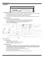
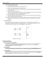
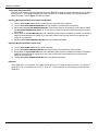
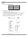
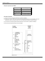
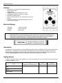
AVS500 User Manual
Features
•
•
•
•
•
•
•
•
•
•
Non-metallic, non-corrosive, water resistant enclosure
Microprocessor based
Variable speed
Adjustable Temperature Differential of 1 to 20°F
Adjustable IDLE Speed (0 to 99% of line voltage)
Extendable temperature probe
Three second full power turn-on to minimize fan motor ice-up
RFI filter
Automatic shut-off with an adjustable differential of 0 to16°F
Two year limited warranty
Electrical Ratings
VOLTAGE:
CURRENT:
PHASES:
115/230V AC, 60Hz
10 Full Load Amps
Single Phase
Warning: Variable speed fan motors draw more current at reduced speeds than maximum speed. Fan motor
specifications show current draw at maximum speed. Current over 10 Amps will cause overheating and
eventual failure of the AVS500 control. Please check current requirements for the fan motor by either
measuring current draw at all speeds or consulting the dealer for information on that fan.
Introduction
Congratulations on the purchase of your new AVS500 environment control! The AVS500 is a microprocessor-based control
that connects to a variable speed fan to efficiently control temperature. This manual will help you get the most from your
AVS500. Take a few minutes to read this manual and become familiar with the proper safety and operating procedures.
Follow the Getting Started section below for step by step instructions on installing your AVS500.
Getting Started
Fill out the information below to help configure your control and verify that you do not exceed the current ratings listed in
the Electrical Ratings section.
Fans
A
Maximum Current Draw Per Fan
B
Number of Fans
A×B
Total Current Draw
Make:
Model:
Voltage Rating:
110418 Rev. 2
2001-02-16
1
AVS500 User Manual
Installation
Warning: The AVS500 should be installed by a qualified electrician
Mounting the Control
• Mount the control with the knockouts at the bottom of the enclosure. Failure to do this will void the warranty.
• Use the knockouts at the bottom of the enclosure for mounting cable connectors.
• DO NOT make additional holes in the enclosure; this will void the warranty.
• Run all wires into the enclosure through the knockouts and connect all ground wires to the ground plate.
Wiring the Control
• Turn off the power before doing any wiring.
• Set the voltage switch to the correct position for the line voltage used (115 or 230V AC).
• Take off the cover when removing electrical knockouts to prevent damaging the control.
• Read the Electrical Ratings section before installing the AVS500 control.
• Connect the wires as shown Figure 1.
Figure1: Wiring Diagram
Temperature Probe
• Connect the probe to the fast-on tabs.
• Gently pull on the probe to extend it out of the enclosure.
• Tighten the compression nut on the strain relief.
Extending the Sensor
• You can extend the temperature sensor to suit your particular application. The maximum length of sensor
depends on the level of electrical noise. With proper installation, sensor lengths of up to 500 feet are possible.
• To extend the sensor, use two wire, 18 AWG jacketed cable for a proper seal at the cable entry hole. We
recommend Belden # 9408, Alpha # 5052, or an equivalent.
• Do not run the sensor cable next to other power cables or inside conduit.
• When crossing other cables, cross at 90°.
• For best results, solder all connections and apply heat shrink to insulate the wires.
110418 Rev. 2
2001-02-16
2
AVS500 User Manual
Follow these steps to extend the sensor:
a) Turn the power off to the control.
b) Remove the four screws from the cover and lift the cover off.
c) Disconnect the sensor connectors from the fast-on tabs.
d) Cut the sensor cable approximately six inches from the connectors and pull the probe end of the sensor
cable out of the box.
e) Insert the extension wire into the box.
f)
Join the connector end of the sensor cable to one end of the extension wire and re-connect the cable to the
fast-on tabs. Apply heat shrink or electrical tape to insulate the wires.
g) Run the extended sensor cable to the desired location.
h) Join the other end of the extension wire to the end of the sensor cable containing the probe. Apply heat
shrink or electrical tape to insulate the wires.
NOTE: If the unit operates erratically with the extended temperature sensor, try running the sensor on a different
path or shortening it. Ensure the sensor cable is not run beside other electrical wires or near electrical
equipment.
Four Zone Averaging
The AVS500 can monitor the temperature in four different zones. The control takes an average of the four
temperatures and operates according to the average temperature. To take advantage of this option, you must
connect four temperature sensors to the unit. See Figure 2 for wiring information.
Figure 2: Four Zone Averaging
Adjusting Settings
Building Temperature Set (TEMP SET)
The TEMP SET is the desired temperature and can be adjusted from 32°F to 100°F. It is also the reference for the
Automatic Shut-Off and Temperature Differential (DIFF) settings. To adjust the setting, turn the BUILDING
TEMPERATURE SET knob to the desired temperature.
Idle Speed (IDLE)
The IDLE speed is the speed of the fan in IDLE mode. To adjust the setting, turn the IDLE SPEED SET knob until the
fan runs at the desired idle speed. IDLE provides minimum ventilation at temperatures below the TEMP SET point.
Automatic Shut-Off
The Automatic Shut-Off is the number of degrees Fahrenheit below the TEMP SET that the fan will switch between OFF
and IDLE. The setting can be adjusted from 0°F to 16°F, or set to OFF. To adjust the setting, turn the AUTOMATIC
SHUT-OFF SET knob to the desired number of degrees from the TEMP SET.
110418 Rev. 2
2001-02-16
3
AVS500 User Manual
Temperature Differential (DIFF)
The DIFF is the number of degrees Fahrenheit above the TEMP SET that the fan reaches maximum speed. The DIFF is
factory set at 6°F. This setting is satisfactory for most requirements. To adjust the setting, use a small screwdriver to
adjust the trimmer. Refer to Figure 1 for trimmer location.
Adjusting Minimum Ventilation in Automatic Shut-Off Mode
a) Turn the IDLE SPEED SET knob fully counter-clockwise, then back ¼ turn clockwise.
b) Turn the BUILDING TEMPERATURE SET knob fully clockwise. The fan should not be running.
c) Slowly turn the BUILDING TEMPERATURE SET knob counter-clockwise. When the fan runs full speed, release
the BUILDING TEMPERATURE SET knob. The fan will run at maximum speed for approximately three seconds,
then at IDLE.
d) Slowly adjust the IDLE SPEED SET knob until a satisfactory IDLE (minimum ventilation) is reached. A voltmeter is
helpful for determining the IDLE voltage. If you are unsure, please consult your fan dealer for the minimum idle
voltage for your fan motor.
e) Adjust the BUILDING TEMPERATURE SET knob to the desired temperature.
Adjusting Minimum Ventilation in OFF mode
a) Turn the IDLE SPEED SET knob fully counter-clockwise.
b) Turn the BUILDING TEMPERATURE SET knob fully clockwise. The fan should be running at IDLE.
c) Slowly adjust the IDLE SPEED SET knob until a satisfactory IDLE (minimum ventilation) is reached. A voltmeter is
helpful for determining the idle voltage. If you are unsure, please consult your fan dealer for the minimum idle
voltage for your fan motor.
d) Turn the BUILDING TEMPERATURE SET knob to the desired temperature.
Hysteresis
The AVS500 has a 1°F hysteresis. This means the fan will turn off 1°F below the point it turned on. For example, if
TEMP SET is 75°F, the fan will turn on at 75°F, off at 74°F. This prevents the fan from flickering on and off at the
TEMP SET.
110418 Rev. 2
2001-02-16
4
AVS500 User Manual
Operation
Example 1, Operation in Automatic Shut-Off Mode
Parameter
Setting
TEMP SET
80ºF
DIFF
6ºF
Automatic Shut-Off
5ºF
IDLE
20% of maximum ventilation
Description of Operation
1) The fan will be off when the temperature is below 75°F.
2) When the temperature increases to 75°F the fan operates at full speed for three seconds, then IDLE. (minimum
ventilation of 20%). The fan will continue to idle between 75°F and 80°F.
3) Between 80°F and 86°F (DIFF) the fan speed will change proportionally with the room temperature. If the room
temperature increases, fan speed increases. If the room temperature decreases, fan speed decreases.
4) The fan will run at maximum speed when the temperature is at or above 86°F (maximum ventilation).
5) When the room temperature drops, the reverse will happen.
Figure 3: Automatic Shut-Off Mode
110418 Rev. 2
2001-02-16
5
AVS500 User Manual
Example 2, Operation in OFF Mode
Parameter
Setting
TEMP SET
80ºF
DIFF
6ºF
Automatic Shut-Off
OFF
IDLE
20% of maximum ventilation
Description of Operation
(1) Below 80°F the fan will operate at IDLE (20% of maximum ventilation).
(2) Between 80°F and 86°F (DIFF) the fan speed will change proportionally with the room temperature. If the room
temperature increases, fan speed increases. If the room temperature decreases, fan speed decreases.
(3) The fan will run at maximum speed when the temperature is at or above 86°F (maximum ventilation).
(4) When the room temperature drops, the reverse happens.
Figure 4: OFF Mode
110418 Rev. 2
2001-02-01
6
AVS500 User Manual
Care and Maintenance
Moisture will not cause a problem with the control if proper care is taken during installation. The control's enclosure is made
of fire retardant plastic and sealed with a rubber gasket. The sensor entry is sealed with a liquid tight cable connector.
Use caution when washing the room with a high-pressure washer. DO NOT direct a high-pressure washer at the control. To
clean the surface of the control, wipe it with a damp cloth.
Maintenance
•
After the first two weeks of operation, remove the cover from the unit and check inside for moisture. Be sure to turn
off the power to the control before removing the cover.
•
If moisture is present, wipe the control out with a dry cloth. Check the cable entry points and rubber gasket for proper
sealing.
•
If the cable connectors are not sealing, apply RTV or Silicon II sealant around the cable.
NOTE: Some silicone sealants release acetic acid while curing. Let the sealant cure completely (one to three days)
before closing the control. Failure to do this may damage the control and void the warranty.
•
Check the control again after two weeks to verify that it is sealing properly.
•
Inspect the control once a year for moisture. Proper care and maintenance will extend the life of the control.
Warning: This control is designed and manufactured to provide reliable performance but is not guaranteed to be 100%
free of defects. Even reliable products may experience occasional failures and this possibility should be
recognized by the user. If this product is used in a life support ventilation system where failure could result in
loss or injury, the user should provide adequate back-up ventilation, supplementary natural ventilation or an
independent failure alarm system. The user's lack of such precautions acknowledges their willingness to
accept the risk of such loss or injury.
110418 Rev. 2
2001-02-01
7
AVS500 User Manual
LIMITED WARRANTY
SCHAEFER FAN CO. warrants this unit, the AVS500, subject to the following terms and conditions: This warranty is valid only to
the original purchaser for a period of two years from the date of manufacturing. The manufacturing date is stated in the first eight
digits of the serial number in the form year-month-day. SCHAEFER FAN CO. hereby warrants that should this product prove
defective by reason of improper workmanship, SCHAEFER FAN CO. will repair the unit, effecting all necessary parts
replacements without charge for either parts or labor.
CONDITIONS
1. Installation must be made in accordance with our enclosed installation instructions.
2. The unit must not have been previously altered, modified, or repaired by anyone other than SCHAEFER FAN CO..
3. The unit must not have been subject to accident, misuse, abuse, or operated or installed contrary to the instructions
contained in this manual. The opinion of SCHAEFER FAN CO. with respect to these matters shall be final.
4. The person requesting the services provided hereunder must be the original purchaser of the unit and furnish proof of
purchase upon request.
5. This warranty is applicable only to the SCHAEFER FAN CO. AVS500 Temperature Control.
6. All transportation charges on units submitted for warranty repair are the responsibility of the purchaser.
7. Return unit together with original proof of purchase to your dealer for warranty service.
EXCEPT TO THE EXTENT PROHIBITED BY APPLICABLE LAW, NO OTHER WARRANTIES, WHETHER EXPRESSED OR
IMPLIED, INCLUDING WARRANTIES OF MERCHANTABILITY AND FITNESS FOR A PARTICULAR PURPOSE, SHALL
APPLY TO THIS UNIT. ANY AND ALL IMPLIED WARRANTIES ARE EXCLUDED. SCHAEFER FAN CO. SHALL NOT BE
LIABLE FOR CONSEQUENTIAL DAMAGES SUSTAINED IN CONNECTION WITH THE SAID UNIT. SCHAEFER FAN CO.
NEITHER ASSUMES NOR AUTHORIZES ANY REPRESENTATIVES OR OTHER PERSONS TO ASSUME FOR IT ANY
OBLIGATION OR LIABILITY OTHER THAN SUCH AS IS EXPRESSLY SET FORTH HEREIN.
SCHAEFER FAN CO. reserves the right to improve or alter the AVS500 without notice.
110418 Rev. 2
2001-02-01
8