1
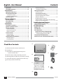
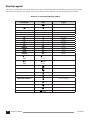
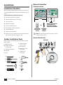
Rain+Birdt ESP-Me enhanced modular controller User Manual FRI 830 AM Symbols CAUTION: Symbol is intended to alert the user to dd important instructions or conditions that could seriously affect irrigation effectivity or controller operation. DIAL: Symbol indicates that the user is required to gg turn the dial on the controller to the appropriate position in order to follow subsequent instructions as described in that section. NOTE: Symbol is intended to alert the user to bb important operating functionality, installation or maintenance instructions. REPEAT: Symbol indicates that a repetition of ee previous steps or may be required in order to continue or complete the controller programming process. SPECIAL FEATURE AVAILABLE: Symbol indicates that a Special Feature is available for the dial position. For more details ee Special Features section of the Advanced User Manual. cc WARNING: Symbol alerts the user to the presence of electricity or electromagnetic energy which may constitute a risk of electric shock, radiation exposure or other hazard. WARNING: You must use special precautions when cc valve wires (also known as station or solenoid wires) are located adjacent to or share a conduit with other wires, such as wires used for landscape lighting, other “low voltage” systems or other “high voltage” power. Be sure to separate and insulate all conductors carefully taking care not to damage wire insulation during installation. An electrical “short” (contact) between the valve wires and another source of power can damage the controller and create a fire hazard. NOTE: This appliance is not intended for use by bb persons (including children) with reduced physical, sensory or mental capabilities, or lack of experience and knowledge, unless they have been given supervision or instruction concerning use of the appliance by a person responsible for their safety. Children should be supervised to ensure that they do not play with the appliance. Disposal of Electronic Waste In compliance with European Directive 2002/96/CE and EURONORM EN50419:2005, this device must not be thrown away with houshold garbage. This device must be the object of an appropriate, selective removal procedure in order to recuperate it. Safety Information WARNING: Date and time are retained by a lithium cc battery which is to be disposed of in accordance with local regulations. WARNING: Use only Rain Bird approved accessory cc devices. Unapproved devices may damage controller and void warranty. For a list of compatible devices go to: www.rainbird.com/controllersupport II II ESP-Me User Manual Questions? In the USA or Canada call Rain Bird Technical Support at 1-800-724-6247 or visit our web site at www.rainbird.com/controllersupport English - User Manual Contents Questions?..............................................................II Check Box Contents..............................................III Station Numbering........................................................... 7 Module Configuration................................................ 7 Wiring Connections...............................................8 Connect Valves................................................................... 8 Connect Master Valve..................................................... 8 Connect Pump Start Relay............................................ 9 Connect Optional Rain Sensor (Wired or Wireless)......................................................... 10 Set Rain Sensor to Active (after installing a rain sensor and removing jumper wire on backplane)....................................... 10 Introduction Welcome to Rain Bird............................................1 The ESP-Me Controller..........................................1 Controller Features........................................................... 1 Controls and Indicators.................................................. 1 Display Legend......................................................2 Advanced Options Seasonal Adjust.....................................................3 Delay Watering.......................................................3 Rain Sensor.............................................................3 Installing Optional Features Connect Optional Accessory............................. 11 Remote Programming........................................ 11 Installation Installation Checklist.............................................4 Gather Installation Tools.......................................4 Mount Controller...................................................4 Choose Location................................................................ 4 Remove Knock-outs......................................................... 4 Mount Controller............................................................... 5 Connect Power.......................................................5 Indoor Model...................................................................... 5 Outdoor Model.................................................................. 6 Station Expansion Modules.................................6 Module Options................................................................. 6 Install Modules................................................................... 7 Check Box Contents Troubleshooting Battery Life.......................................................... 12 Reset Button........................................................ 12 Error Detection................................................... 12 Programming Errors (blinking LED)...................... 12 Electrical Errors (non-blinking LED)....................... 12 Clearing Electrical Error Alerts............................. 12 Frequently Asked Questions............................. 13 Electrical Issues (solid LED illuminated).......... 14 a. e. a. ESP-Me Controller (outdoor model shown) b. User Manual c. Quick Reference Guide/Programming Chart (inside controller door) d. Special Features Card(s) depending on model f. b. e. Mounting Hardware (Wire nuts for outdoor unit only) 25.5VAC 120V ESP-Meenhanced enhanced modular modular controller controller ESP-Me User Manual Rapid Start Manual f. Grounded 120V Power Supply (indoor model only) English..............................1 Español...........................21 g. Door Keys (outdoor model only) Français..........................41 c. g. d. III III ESP-Me User Manual Contents Introduction Welcome to Rain Bird Thank you for choosing the ESP-Me Modular Controller from Rain Bird. FRI 830 AM For more than 70 years, the world’s top irrigation contractors have chosen Rain Bird for the highest quality products and services available worldwide. The ESP-Me Controller Controller Features llExpandable up to 22 stations with 3 or 6 station modules llSupports a master valve or pump start relay and a rain sensor llSeasonal Adjust can be applied to a specific program or to ALL programs (Range is from 200% down to 5%) llDelay Watering (Rain Delay) can prevent irrigation for up to 14 days ll4 available programs (A,B,C,D) llManual Water Station or Program allows immediate NOTE: Only one program can run at a time. bb watering of an individual station or an entire program ll6 start times for each program llTest All Stations llAutomatic alarm alerts llTotal Run Time Calculator by program ll1 Touch Watering - in the Auto-Run dial position, press and hold the right arrow key llSensor Bypass by Station Controls and Indicators Test All Stations Key operational features of the ESP-Me Controller: Programming Dial Water Start Times Set Station Run Times Program Select Button Rotate the dial to select Up to 6 per program 1 minute to 6 hours Select Watering Program programming functions. A, B, C, or D. Alarm Indicator Illuminates solid or flashes when an alarm condition exists. Manual Watering Rain Sensor Applies to all programs but can be set to bypass individual stations. FRI 830 Delay Watering Up to 14 days. Seasonal Adjust Adjust value from 5% up to 200% Water Day(s) Options By Day, Odd, Even or Cyclic. 1 1 ESP-Me User Manual ESP-Me Controller Front Panel AM Back/Next Buttons Select programming options. – / + Buttons Adjust program settings. (Press and HOLD - or + to accelerate adjustments). Hold to Start Manual irrigation. Introduction Display Legend This manual uses USA domestic icons for illustration purposes. The following table lists the differences between the domestic and international display screen symbols. Choose your voltage below to determine the LCD symbols for your controller. Domestic vs. International Display Symbols 120V & 240V OFF 230V English Off Next Watering Day NEXT MO TU WE TH FR SA SU DAY MONTH YEAR HOUR MINUTE 1, 3, 5... ODD 2,4, 6... EVEN STATION 1, 3, 5...29 Monday Tuesday Wednesday Thursday Friday Saturday Sunday Day Month Year Hour Minute Odd Days 1, 3, 5 2,4, 6...30 Even Days 2, 4, 6 Station START TIME Start Time RUN TIME Run Time REMAINING RUN TIME Remaining Run Time SEASONAL ADJUST % Seasonal Adjust DELAY Rain Delay MANUAL Manual Watering TEST Test All Stations DELAY 2 2 1 2 3 4 5 6 7 DD MM YY HH MM ESP-Me User Manual DELAY Delay Between Valves Introduction Advanced Options Delay Watering For Basic Setup, see the Quick Reference Guide located inside the controller door. Delay watering if irrigation is not needed. Seasonal Adjust 1. Turn the dial to Delay Watering. Increase or decrease watering duration based on seasonal weather conditions. 2. Press or to set the DAYS REMAINING. The next watering days remaining will update on the display to indicate when watering will resume. 1. Turn the dial to Seasonal Adjust %. 2. Press or to increase or decrease the Seasonal Adjust percentage setting. (5 - 200%) WE NEXT 3 PROGRAM SELECT DAYS REMAINING ABCD PGM AB CD 100 ALL SEASONAL ADJ Rain Sensor 3. If adjustment will not be applied to all programs, press the Program Select button to select the desired program. NOTE: Displayed run times are inclusive of any bb seasonal adjustment made. Example: Station 1 has a run time set for 10 minutes. The program Seasonal Adjusted value is now set to 150%. The new actual run time is 10 minutes x 150 % = 15 minutes. Set the controller to obey or ignore a rain SPECIAL FEATURE AVAILABLE sensor. The Rain Sensor setting applies to all programs and is not program specific. However, you can set any station to Bypass (Ignore) the sensor. For more details see the Special Features card or the Advanced User Manual. 1. Turn the dial to Rain Sensor. 2. Press or to select ACTIVE or BYPASS. PGM A STATION HOUR MINUTES 1 015 SEASONAL ADJ bb RUN TIME NOTE: Running a Manual Station or Program will use the Seasonal Adjusted value. 3 3 ESP-Me User Manual BYPASS Advanced Options Installation Mount Controller Installation Checklist Choose Location When installing the ESP-Me controller for the first time, it is recommended that you complete the following steps in order. A check-off box is provided for each step: Check box contents (see page III) Gather installation tools (see below) 11 IN. 3 IN. Select a location Mount the controller MOUNT CONTROLLER IN PROXIMITY TO ELECTRICAL POWER SOURCE AS REQUIRED OR Connect controller power Install station modules (optional) GROUNDED ELECTRICAL OUTLET Connect field wires Complete the installation If a Rain Sensor is installed, turn the dial to Rain Sensor and set status to “Active” using the + key Gather Installation Tools Before beginning installation, gather the following tools and materials: f. Drill and drill bit a. Marking pencil (for #8 screws) b. Phillips screwdriver g. Wire Stripper (#1, #2, #3 tip) h. Mounting Screws c. Flathead screwdriver (included) d. Hammer i. Wall Anchors EXTERNAL POWER SOURCE NOTE: The operating temperature range is 14°F to bb +149°F (-10°C to +65°C). Remove Knock-outs OPTIONAL (if needed) e. Level a. f. b. c. g. d. h. e. i. 4 4 ESP-Me User Manual Installation Connect Power Mount Controller WARNING: DO NOT plug in the transformer or cc connect external power until you have completed 2. 1. 1/8 IN. and checked all wiring connections. WARNING: All electrical connections and wiring cc runs must comply with local building codes. NOTE: Use wall anchors (not included) if needed. bb Electrical Specifications (230V only) 3. GND SENS 24 VAC 4. VT MV COM 1 2 3 4 VT MV COM 1 2 3 4 VT = VALVE TEST CONNECT 120 VAC 5 6 7 8 9 10 Some building codes require that only a licensed or certified electrician can make the power connections. Please check with your local building code for guidance. Only professional personnel shall install the controller. 11 12 13 14 15 16 17 18 19 20 21 22 Input 230VAC, 0.2AMP, 50/60Hz Output 25.5VAC, 1.0AMP, 50/60Hz Indoor Model 1. Route the transformer power cord through the conduit opening at the bottom left of the unit. Knot the cable/ cord inside the controller cabinet to prevent it from being pulled out. GND SENS 24 VAC CAUTION: Do not route the power cord through the dd field wire opening at the bottom right of the unit. VT MV COM 1 2 3 4 5 6 7 8 9 10 11 12 13 14 15 16 17 18 19 20 21 22 VT MV COM 1 2 3 4 VT = VALVE TEST 1. 5 5 ESP-Me User Manual Installation Outdoor Model For 230V only: WARNING: Electric shock can cause severe injury or cc death. Make sure power supply is turned OFF before 3. connecting power wires. L N Power Wiring Connections 120VAC (USA) 230VAC (International) Black supply wire (hot) to the Black supply wire (hot) to the black transformer black transformer wire wire White supply wire (neutral) to Blue supply wire (neutral) to the blue the white transformer wire transformer wire Green supply wire (ground) Green-with-yellow-stripe supply wire (ground) to the green transformer wire to the green-with-yellow-stripe transformer wire ( ) GND SENS 24 VAC 1. VT MV COM 1 2 3 4 5 6 7 8 9 10 11 12 13 14 15 16 17 18 19 20 21 22 Use either the provided wire nuts or the NOTE: installed connector for this step. WARNING: Ground wire must be connected to cc provide electrical surge protection. Permanently mounted conduit shall be used for connecting main voltage to the controller. VT MV COM Station Expansion Modules 1 2 3 4 VT = VALVE TEST CONNECT 120 VAC Additional Station Modules can increase the number of available stations up to 22. Module Options Base Module (included) GN D SEN S 24 VA C 2. VT MV COM 1 2 3 4 5 6 7 8 9 10 11 12 13 14 15 16 Expansion Modules (sold separately) 17 18 19 20 21 22 VT MV CO M 1 2 3 4 VT = VALVE T EST VT MV COM For 120V: GND SENS 24 VAC 3. VT MV COM 1 2 3 4 5 6 7 8 9 10 11 12 13 14 15 16 17 18 19 20 21 22 3-STATION (ESPSM3) VT MV COM 6-STATION (ESPSM6) 1 2 3 4 VT = VALVE TEST NOTE: 6-Station module is compatible only with the bb ESP-Me. They are not backwards compatible with the previous vintage controller. NOTE: For ideal station sequencing, it is bb recommended that a 6-Station module always be installed in Bay 2. For more details see Station Numbering section. 6 6 ESP-Me User Manual Installation Install Modules Module Configuration Why Proper Configuration Is So Important 1. Example of installation with station numbering gaps: A total of 19 stations are installed. The Base Module is installed in Bay 1 and uses Stations 1 through 4. A 6-Station Expansion Module is installed in Bays 2 and 3. A 3-Station module is installed in Bay 4 and uses 2. stations numbered 17 through 19. Because a 3-Station module is installed in Bay 4, only the first three station numbers assigned to that bay will be used and the unused numbers will be “reserved” for future use. During programming, the controller will skip any unused station numbers, creating a gap in station numbering. Station Numbering Fixed Station Numbering Description The controller is configured with Fixed Station Numbering. Each bay is set up to accept a 6 station module and reserve the station number for future use if a 6 station module is NOT installed in Bays 2, 3 or 4. STATION Station numbers are pre-assigned as follows: Bay 1 Bay 2 Bay 3 Bay 4 VT MV COM 1 2 3 4 5 6 7 8 9 10 11 12 13 14 15 16 17 18 19 20 21 22 VT MV COM In our example a 3-Station module was installed in Bay 4, so stations 20-22 will be unavailable for programming. During programming the missing stations will show on the display as 20NOMOD, 21NOMOD, etc. 20NOMOD The screen displays “20NOMOD” with the “20” flashing to indicate that Station 20 (and also 21-22) are unused and unavailable for programming. NOTE: Station numbering gaps will not prevent the bb controller from operating properly. It only affects station numbering. During programming when connected to AC power, the controller will skip any unused stations where a module is not installed. Example Of Optimum Installation Of 19 Stations 7 7 ESP-Me User Manual Installation Wiring Connections Connect Master Valve Connect the valve wires for each station and for a (optional) Master Valve, Pump Start Relay or Rain Sensor. Connect an optional Master Valve to the ESP-Me controller. GND 24 VAC CAUTION: Do not route the valve wires through the dd same opening as the power wiring. SENS CAUTION: Do not route the master valve wires dd through the same opening as the power wiring. Connect Valves VT MV COM 1 2 3 4 5 6 7 8 9 10 11 12 13 14 15 16 17 18 19 20 21 22 VT MV COM 1. To perform a Valve Test- connect the common wire to the “COM” terminal and the power wire to the “VT” terminal. This will immediately turn the valve “ON” . 1 2 3 4 VT = VALVE TEST CONNECT 120 VAC WARNING: The “VT” terminal is always powered cc “ON”. POWER GND SENS 24 VAC 1. VT MV COM 1 2 3 4 5 6 7 8 9 10 11 12 13 14 15 16 17 18 19 20 21 22 COMMON MASTER VALVE VT MV COM 1 2 3 4 VT = VALVE TEST CONNECT 120 VAC POWER STATION 2 VALVE, ETC. STATION 1 VALVE 8 8 ESP-Me User Manual COMMON Installation Connect an optional Pump Start Relay to the ESP-Me controller. bb The following Rain Bird Pump Start Relays are available in the USA only: RBSR24WG1 - Universal Pump Start Relay For the most up to date compatibility list of pump start relays, visit our website at: www.rainbird.com/ controllersupport GND SENS GND 1 2 3 4 VT = VALVE TEST 120 VAC JUMPER WIRES ON UNUSED STATIONS NOTE: Default run times for program A is 10 minutes bb for stations 1-4. CAUTION: To avoid Dead Heading your pump do dd one of the following for all unused stations (module 5 6 7 8 9 10 11 12 13 14 15 16 llConnect jumper wire across unused stations. llSet the station to Bypass the MV. bb 24 VAC 17 18 19 20 21 22 llSet Station Run Time(s) to 0. NOTE: This controller is not compatible with the Hunter© PSR22 and PSR52. To Bypass the Master Valve for any Station: 1. Turn the dial to Set Station Run Times. 2. Press and HOLD both and at the same time. 17 18 19 20 21 22 VT MV COM 3. Press or to select the desired Station; then press or to set MV ON or MV OFF. 1 2 3 4 VT = VALVE TEST CONNECT 120 VAC RELAY INPUT 11 12 13 14 15 16 installed but not connected to a station wire): RBPL24WG1 - Pump Start Relay with Pressure Switch VT MV COM 1 2 3 4 5 6 7 8 9 10 CONNECT CAUTION: Do not route the pump start relay wires dd through the same opening as the power wiring. current of 5VA. VT MV COM 1 2 3 4 VT MV COM NOTE: The ESP-Me controller DOES NOT provide main power for a pump. NOTE: The controller can support a maximum Coil bb Inrush current of 11VA and a maximum Coil Hold SENS 24 VAC Connect Pump Start Relay COMMON STATION 1 MVON PUMP START RELAY TO EXTERNAL POWER SOURCE 9 9 ESP-Me User Manual Installation Connect Optional Rain Sensor (Wired or Wireless) Set Rain Sensor to Active (after installing a rain sensor and removing jumper wire on backplane) Connect an optional rain sensor to the ESP-Me controller. Set the controller to obey a rain sensor. NOTE: The ESP-Me Controller is not compatible with bb with a Normally Open rain sensor. It is designed for 1. Turn the dial to Rain Sensor. 2. Press or to select ACTIVE. use with a Normally Closed rain sensor. GND SENS 24 VAC On the terminal strip, remove the yellow jumper wire from the SENS terminals and discard. VT MV COM 1 2 3 4 5 6 7 8 9 10 11 12 13 14 15 16 17 18 19 20 21 22 ACTIVE VT MV COM 1 2 3 4 VT = VALVE TEST CONNECT 120 VAC GND SENS 24 VAC REMOVE AND DISCARD JUMPER WIRE VT MV COM 1 2 3 4 VT MV COM The rain sensor symbol will show on the display in AUTO RUN or OFF when Rain Sensor is set to BYPASS. 5 6 7 8 9 10 11 12 13 14 15 16 17 18 19 20 21 22 SYMBOL SHOWN 1 2 3 4 VT = VALVE TEST CONNECT sun 427 PM 120 VAC When Rain Sensor is set to ACTIVE, no symbol is shown. WIRED RAIN SENSOR SHOWN. OPTIONAL WIRELESS RAIN SENSOR RAIN BIRD MODEL # WR2RC OR WR2RFC IS AVAILABLE SENSOR WIRES NO SYMBOL sun 427 PM NOTE: For more details see Rain Sensor in the bb Advanced Options section of the Advanced User Manual. NOTE: The Alert light no longer illuminates when bb irrigation is delayed due to rainfall. 1010 ESP-Me User Manual Installation Installing Optional Features Connect Optional Accessory NOTE: Use only Rain Bird approved devices with bb 5 pin accessory port. Unapproved devices may damage controller and void warranty. Remote Programming Program the front panel remotely on battery power. HOMEOWNER NOTE: The following bb do not require a 9V battery to maintain: Date and Time are maintained up to 10 years by an internal Lithium battery. Programs and Settings are permanently stored in controllers non-volatile memory. 1111 ESP-Me User Manual Installing Optional Features Troubleshooting The Alert LED light on the ESP-Me controller front panel will light up to indicate an alarm condition: Battery Life If the display repeatedly shows “-- -- -- -- --” when using a 9V battery for remote programming, replace the battery. ALERT Programming Errors (blinking LED) Error Alert LED Error Message On Display Press RESET if the controller is not working properly. No Start Times are set BLINK NO START TIMES The Reset button resets the controller. Active irrigation is canceled, but all previously programmed watering schedules remain stored in memory. Irrigation will resume at the next scheduled Start Time. No Run Times are set BLINK NO RUN TIMES Reset Button 1. Insert a small tool into the access hole and press until the controller is reset. NOTE: We suggest using a non-metallic object such bb as a pencil or pen to press the Reset button. 1. No Watering Days are set BLINK NO WATER DAYS The ESP-Me controller will reset or clear when the error is corrected. NOTE: The dial must be in the AUTO RUN position for bb an Alert message to appear on the display. Electrical Errors (non-blinking LED) Error Alert LED Error Message On Display Master Valve short SOLID MASTER VALVE/PUMP WIRE SHORTED OR HIGH CURRENT Station short STATION “X” WIRE SHORTED SOLID When an electrical error is detected, irrigation for the affected station is cancelled and watering advances to the next operable station in the program. Error Detection The ESP-Me controller has built-in error detection that can automatically generate an alert caused by an essential programming error or if an electrical short condition is detected. The controller will attempt to water the affected station again at the next scheduled watering. Completion of a successful watering will clear the error condition associated with that station. Clearing Electrical Error Alerts Turn the dial to the AUTO RUN position to view the error message on the display. To clear the Alert, press the right arrow key . 1212 ESP-Me User Manual Troubleshooting Frequently Asked Questions Problem Possible Cause Possible Solution Display shows a program is active, but system isn’t watering. Water source not supplying water. Verify there is no disruption to the main water line and that all other water supply lines are open and functioning properly. Wiring is loose or not properly connected. Check that field wiring and master valve or pump start relay wiring is securely connected at the controller and in the field. Field wires are corroded or damaged. Check field wiring for damage and replace if necessary. Check wiring connections and replace with watertight splice connectors if needed. Loss of AC power. When there is a power loss and a 9 volt battery is installed, the system does not irrigate but programs show as remaining active. No Power detected. Check circuit breaker and that unit is plugged into socket or properly connected to power source. Controller may be plugged into a GFI outlet or an outlet that is wired to a GFI outlet. Check power to the outlet or reset the circuit breaker. Connected rain sensor may be activated. Set Rain Sensor to BYPASS to ignore the rain sensor. If watering resumes, the sensor is operating properly and no further correction is needed. Connected rain sensor may not be operating properly. Let the rain sensor dry out, or disconnect it from the controller terminal strip and replace it with a jumper wire connecting the two SENS terminals, or set to Bypass. If no rain sensor is connected, the jumper wire connecting the two SENS terminals on the terminal strip may be missing or damaged. Move dial position to Sensor Bypass and set to Bypass. This is normal operation. The ESP-Me does not consider the interruption of irrigation due to rainfall an alarm condition. This is normal operation. NO AC message on display. Programmed schedules do not start. It just rained and the alarm light is not illuminated, why? 1313 ESP-Me User Manual Troubleshooting Electrical Issues (solid LED illuminated) Problem Possible Cause Possible Solution Display is blank, frozen or will not accept programming. Power not reaching the controller. Verify the main AC power supply is securely plugged in or connected and working properly. Controller needs to be reset. Press the Reset Button. For details see “Reset Button” section. An electrical surge may have interfered with the controller’s electronics. Unplug the controller for 2 minutes, then plug it back in. If there is no permanent damage, the controller should accept programming and resume normal operation. Automatic error detection indicates a problem by Alert LED and an error message on display. Short circuit or overload condition Identify and repair the fault in the wiring. Refer to in valve, master valve or pump start compatible pump start relays. For details see “Connect relay wiring. Pump Start Relay” section. LED is flashing or solidly illuminated but I see no message on the LCD. Dial not in AUTO RUN position. Turn dial to AUTO RUN position. for more details visit www.rainbird.com/controllersupport 1414 ESP-Me User Manual Troubleshooting Declaration of Conformity Rain Bird Corporation hereby declares that the ESP-Me irrigation controller families conform to the European Directives 2004/108/EC for “Electromagnetic Compatibility” and 2006/95/EC for “Low Voltage” Place San Diego Signature Full Name Ryan L. Walker Position Director Rain Bird Corporation 970 W. Sierra Madre Azusa, California 91702 U.S.A 626-963-9311 Rain Bird International, Inc. 145 North Grand Avenue Glendora, CA 91741 U.S.A 626-963-9311 Rain Bird Europe 900 rue-Ampere, BP 72000 13792 Aix-en-Provence CEDEX 3 FRANCE (33) 04 42 24 44 61 Technical Services for U.S. and Canada only: 1 (800) RAINBIRD www.rainbird.com FCC Part 15 This equipment has been tested and found to comply with the limits for a Class B digital device, pursuant to Part 15 of the FCC Rules. These limits are designed to provide reasonable protection against harmful interference in a residential installation. This equipment generates, uses, and can radiate radio frequency energy and, if not installed and used in accordance with the instructions, may cause harmful interference to radio communications. However, there is no guarantee that interference will not occur in a particular installation. If the equipment does cause harmful interference to radio or television reception, which can be determined by turning the equipment off and on, the user is encouraged to try to correct the interference by the following measures: Reorient or relocate the receiving antenna. Increase the separation between the equipment and receiver. Connect the equipment into an outlet on a circuit different from that to which the receiver is connected. Consult the dealer or an experienced radio/TV technician for help. Changes or modifications not expressly approved by Rain Bird Corporation could void the user's authority to operate the equipment. This product was FCC certified under test conditions that included the use of shielded I/O cables and connectors between system components. To bin in compliance with FCC regulations, the user must use shielded cables and connectors and install them properly. Rain+Birdt Rain Bird Corporation 6991 East Southpoint Road Tucson, AZ 85756 USA Tel: (520) 741-6100 Fax: (520) 741-6522 Rain Bird International 1000 West Sierra Madre Avenue Azusa, CA 91702 USA Tel: +1 (626) 963-9311 Fax: +1 (626) 852-7343 Rain Bird Europe SNC 900, rue Ampère, B.P. 72000 13792 Aix en Provence Cedex 3 FRANCE Tel: (33) 4 42 24 44 61 Fax: (33) 4 42 24 24 72 Rain Bird France SNC 900, rue Ampère, B.P. 72000 13792 Aix en Provence Cedex 3 FRANCE Tel: (33) 4 42 24 44 61 Fax: (33) 4 42 24 24 72 Rain Bird Ibérica. S.A. Polígono Ind. Pinares Llanos C/ Carpinteros, 12, 2ºC 28670 Villaviciosa de Odón, Madrid ESPAÑA Tel: (34) 91 632 48 10 Fax: (34) 91 632 46 45 Rain Bird Desutschland GmbH Oberjesinger Str. 53 71083 Herrenberg-Kuppingen DEUTSCHLAND Tel: (49) 07032 99010 Fax: (49) 07032 9901 11 Rain Bird Sverige AB Fleningevägen 315 254 77 Fleninge SWEDEN Tel: (46) 42 25 04 80 Fax : (46) 42 20 40 65 Rain Bird Turkey İstiklal Mahallesi, Alemdağ Caddesi, No.262 34760 Ümraniye İstanbul TÜRKİYE Tel: (90) 216 443 75 23 Fax: (90) 216 461 74 52 www.rainbird.com www.rainbird.eu 1-800-724-6247 2013 Rain Bird Corporation 14FE13 Registered trademark of Rain Bird Corporation D50039EO