1
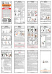
User Manual (Rodeostop B100) 09/2014 INSTRUCTIONS FOR USE RODEOSTOP B100 SUMMARY Page I. General information .................................................................................................... 2 II. Anticipated use and applications................................................................................ 2 III. Limits to use ................................................................................................................ 2 IV. Rescue..........................................................................................................................3 V. Modification of the equipment ......................................................................................3 VI. Checking the equipment before use ............................................................................3 VII. Installing the rope .........................................................................................................4 VIII. Characteristics of personal safety equipment which require checking before use.......5 IX. The complete device must be immediately withdrawn from circulation if ....................5 X. Anchorage point requirements......................................................................................5 XI. Instructions for linking up to the anchorage point.........................................................6 XII. Instructions for linking the anchorage point to the harness ..........................................6 XIII. For fall arrest systems it is essential that......................................................................6 XIV. A fall arrest device is the only apparatus......................................................................7 XV. Warning : Check the area where the RODEOSTOP B100 is to be used......................7 XVI. The potential danger affecting the performance of the equipment...............................7 XVII. Protection when transporting the material....................................................................7 XVIII. The simplification of symbols & marking on the equipment..........................................8 XIX. Contacting the head office of Protectman the manufacturer of the RODEOSTOP B100..............................................................................................................................8 XX. For the security and information of the non-France based purchasers of the RODEOSTOP B100......................................................................................................8 XXI. Cleaning and disinfecting the RODEOSTOP B100.....................................................9 XXII. The Periodic check-up................................................................................................10 ~1~ I. GENERAL INFORMATION AND DISCRIPTION The fall arrest device RODEOSTOP B100 meets and complies with all the requirements of the European directives 89/686 CEE. It conforms to standards CE0082 – EN360 : 2002 A.R.A. Tests have been carried out with semi-static antipode rope BEAL (ref: CE1891 type A Ø10/10.5 mm with static resistance in excess of 1500 DaN) II. ANTICIPATED USE AND APPLICATION The fall arrest device RODEOSTOP B100 must have its anchorage point two metres above a platform and must be attached with connectors CE EN362 with a minimum resistance in excess of Rr 1500 DaN. All the complementary components used must be European CE recognised, CE referenced and be compatible with each other. (Read carefully the operating instructions for each item). The RODEOSTOP B100 must be used with: A. An anchorage point complying with European standard CE EN 795. B. A connector complying with European standard CE EN 362 linking the anchorage point to RODEOSTOP B100. C. A connector complying with European standard CE EN 362 links the RODEOSTOP B100 to the harness. D. A fall arrest device harness complying with European standard CE EN 361 equipped with dorsal, sternum and ventral attachment points. E. Nothing is to be added or come between the connector linking the RODEOSTOP B100 to the harness. III. RESTRICTIONS OF USE OF THE RODEOSTOP B100 The angle of the pendulum movement must not exceed 30 degrees. Do not use above or inside a tank or cistern containing corrosive products. Never put a metallic cable on the pulley inside the RODEOSTOP B100. Great care must be taken to ensure that everyone using the fall arrest device is in good physical health. An unforeseen emergency such as an arrest of the RODEOSTOP B100 can make heavy demands on the user, so it is essential to be fit in order to cope successfully with such situations. ~2~ The device is to be used only by a competent and trained person. The RODEOSTOP B100 should only be used by one person at a time who does not exceed 130 kilos in weight. The person must read or have explained to him/her the instructions. Disregard of the instructions can lead to very serious risks and injury and even to death. IV. RESCUE Safety procedures must be set up well in advance of use so that any problem arising later can be dealt with quickly and effectively. Another person must also be present to get help in an emergency. If the help is slow in coming the RODEOSTOP B100 enables the user to lower himself down alone gently with a “8” descender (“8” shaped buckle) controlling his own movements such as stopping and starting. Alternatively someone on the ground can evacuate the user in difficulty in the same way and in complete safety. V. MODIFICATION OF THE EQUIPMENT Under no circumstances should the RODEOSTOP B100 be modified or opened up. Repairs can only be effected by people authorized by the manufacturer. All repairs must be done by the manufacturer on the basis of an estimate or an allinclusive price for the parts or in a workshop authorized by the manufacturer. Any departure from these restrictions will invalidate the manufacturer’s guarantee. VI. CHECKING THE EQUIPMENT BEFORE USE Before use check that the anchorage point is completely vertical above the work place and that it can accept a charge of 1500 DaN. Check that everything on the RODEOSTOP B100 is in a perfect state and that all screws are tightly fixed. ~3~ VII. INSTALLING THE ROPE Rope installation in the RODEOSTOP B100 is easy. At the bottom of the device introduce the rope (3) in the U of the groove (13) inside the brace (11). Pull the rope (3) through by pushing it into the centre of the pulley and bringing the rope out again (3) on the other side in the U slot inside the brace (11). See sketch below. Bottom view internal view side view Make sure that the rope (3) has passed all round the centre of the pulley (4) until it comes out on the other side in the U groove (13) between the two braces (11) at the bottom of the apparatus. Check again that the safety rope (3) is correctly installed in the apparatus by gently pulling it in both directions. The rope should circulate freely on the pulley. Then give the rope a sharp pull. This should stop the rope and block it. Do the same with the other side. This should produce the same results by stopping and blocking the rope. ~4~ VIII. CHARACTERISTICS OF PERSONAL SAFETY Equipment that require checking before use. Carefully read everything, but in particular sections VII, XV and XVI of the instructions for Use of the RODEOSTOP B100 before use, then take time to check all the equipment. Harness: check the straps, the stitching of the seams, the state of the buckles and the signs of corrosion and warping. Also the general cleanliness and freedom from dirt. Sling: check the condition steel or strap, signs of cracking, the good state of the markings and traces of knocks. Check that all fixtures are tight and in good condition. Hold up the apparatus and check that the full length of the rope is in good working order with no traces of burning, oil, wear and tear, cuts and no sign of parasitic knots. Also check again to ensure the rope functions properly and stops and blocks correctly. To be absolutely safe only use connectors European reference: EN 362. IX. THE APPARATUS MUST BE IMMEDIATELY WITHDRAWN FROM CIRCULATION IF…… …..there are doubts about the safety system. …..when during a check-up or for any other reason the fall arrest device shows signs of damage through a knock or other cause of malfunction, it is imperative to put the apparatus out of service and attach a label to that effect. Then the apparatus should be sent to a centre authorized by a manufacture for repair. …..it has been used for arresting a fall, remove from use and get a competent person to give another check-up. X. ANCHORAGE POINT REQUIREMENTS Never work above the fall arrest device or under an anchorage point. The fall arrest device must be placed vertically at least two metres above the work place of the person attached by the dorsal, sternum, or ventral attachment on his harness. The anchorage point must be completely clear of any obstacle which could jeopardise the smooth functioning of the fall arrest device. ~5~ The choice and fixing of the anchorage point is the responsibility of the site manager or specialised firm. XI. INSTRUCTIONS FOR LINKING UP TO THE ANCHORAGE POINT Install the anchorage point as explained in section X. Link up the fall arrest device to the anchorage point with a connector complying with European standard EN 362 or with a sling or strap complying with European standards or alternatively with steel cable capable of withstanding a minimum charge of 2000 kilos. XII. INSTRUCTIONS FOR LINKING UP THE ANCHORAGE POINT TO THE HARNESS Always be careful to link up the RODEOSTOP B100 safety system by means of the dorsal, sternum or ventral connector on the harness. Use an “8” shaped buckle if necessary. Never put an extension or whatever between the “8” shaped buckle of the safety rope and the dorsal, sternum or ventral attachments on the harness. Only the connector of European standard EN 362 is designed for that. XIII. FOR THE FALL ARREST SYSTEM IT IS ESSENTIAL THAT…... .…..the person going up should take great care that the safety rope does not build up any slack. That should never happen if the installation has been properly done: the rope should always be taut. However if the safety rope does become slack then rope tension can be re-established by lowering the apparatus and going down a little or by giving the safety rope a gentle pull – or two. ~6~ XIV. A FALL ARREST DEVICE IS THE ONLY APPARATUS.….. …..wherever there is a risk of a fall it is essential to use a fall arrest harness equipped with dorsal, sternum and ventral connectors fitted above the waist with a comfortable and adjustable seat. XV. WARNING: CHECK THE AREA WHERE THE RODEOSTOP B100 IS TO BE USED Wherever there is a risk of a fall it is important to ensure there are no obstacles or obstructions under the person using the fall arrest device. A large open space is essential for such activity. There must be an area of at least the height of the person plus another 1.35 metres for a taut, vertical and rectilinear rope system. XVI. THE POTENTIAL DANGERS AFFECTING THE PERFORMANCE OF THE EQUIPMENT Make quite sure that the ropes and straps are protected from danger caused by rubbing, scraping and friction caused by abrasive and sharp edged surfaces, acute pointed angles, cuts from Stanley Knifes; chemical products, heat; bits of soldering or welding, dust, sand, cement getting inside the apparatus. Do not release a person from the device by cutting the rope with a Stanley Knife. XVII. PROTECTION WHILE TRANSPORTING THE MATERIAL It is very important to protect the RODEOSTOP B100 during transport in order to avoid damage. All the parts of the fall arrest system (ropes, harness, connectors) should be carefully placed in a suitable container and sheltered from knocks and rubbing into each other. On return to the site the RODEOSTOP B100 should be stored away carefully. There is a real risk that the ropes, harness and fall arrest device scattered higgledy – piggledy on the dusty, sandy floor of a vehicle will quickly become unusable if taken to the site in such a way. ~7~ XVIII. THE SIGNIFICANCE OF SYMBOLS AND MARKINGS ON THE EQUIPMENT The laser-engraved markings on the stainless steel casing of the RODEOSTOP B100 carry important information. a dial of twelve months a semicircle dial of years a book (read the instructions for use) a pictogram representing a maximum weight of 130 kg the European standard reference CE0082-EN360 : 2002 A.R.A. the inscription: automatic full arrest device, the name and trade mark – Rodeostop B100 the lot number – for example lot 0101 serial number 0001 a means of identification : manufacturer’s name and address: PROTECTMAN tel. (33) 0145345205 fax: (33) 0954178012 www.rodeostop.com an oblique dotted line showing ropes on each side under stainless steel casing engraved 10/10.5mm semi-static CE EN 1891A INFORMATION ON THE DIE-STAMPING: Marking by die-stamping will be effected as and when appropriate. This will be the diestamping of the months and years directly onto the stainless steel casing during the dismantling necessitated by the obligatory annual check-up. XIX. CONTACTING THE HEAD OFFICE OF THE MANUFACTURER OF RODEOSTOP B100 Protectman 2 Rue Maisant 92190 MEUDON FRANCE Tel: 00 331 4534 5205 Fax: 00 339 5417 8012 Email: [email protected] XX. FOR THE SECURITY AND INFORMATION OF NON FRANCE-BASED PURCHASERS OF THE RODEOSTOP B100 If the fall arrest device is sold in a country other than France, then it is obligatory to provide and include the following with the apparatus: The instructions for use, for maintenance, periodic check-ups and repair in the language of the country. ~8~ In accordance with European legislation operating instructions for the RODEOSTOP B100 which is originally for exclusive distribution in France must be translated into the principal languages later. XXI. CLEANING AND DISINFECTING THE RODEOSTOP B100 Fall arrest devices that have been used in contaminated places must be decontaminated on the spot by the appropriate specialized services. Do not move or use before proper decontamination has been carried out. It is categorically forbidden to use compressed air or water to clean the fall arrest device. Cleaning should only be done with a damp sponge or if absolutely necessary a few drops of washing-up liquid or soap may be added. Rinse and dry with a moist cloth. If water does get into the apparatus hang it up to prevent the water from stagnating inside. It is important to be able to use a device which is clean and in good condition, so in order to do that these cleaning methods must be strictly adhered to. DRYING WET EQUIPMENT : If the fall arrest device has got wet then dry it out naturally away from direct heat. STORING CONDITIONS : The material must be stored in a dry and clean place well away from all sources of heat and humidity. Fall arrest devices must not be subject to vibrations or sunlight to avoid warping. The storage place used for the apparatus must be free therefore from vibrations and sunlight. Dirty fall arrest devices attract vermin and rodents, so hang the RODEOSTOP B100 on a hook and do not put on the ground. MAINTENANCE AND LUBRICATION : The RODEOSTOP B100 requires very little maintenance. Keeping it clean is a guarantee for a long life for the apparatus. Never oil or grease the RODEOSTOP B100 Never dismantle the RODEOSTOP B100 For security reasons all repairs must be done at the factory or by an authorized repairer for a fixed price quotation for the parts changed. LIFETIME : ~9~ The lifetime of the product is difficult to predict, it depends on the use and maintenance of equipment. She is 5 years for normal use, and 2 years for heavy use, this life may be renewed at the end of the results of periodic inspection. XXII. THE PERIODIC CHECK-UP The automatic return RODEOSTOP B100 must be sent back to the factory or an authorized centre every twelve months for a check-up and renewal date of next check-up: see the check-up sheet or twelve months after the purchase date. - Protectman France 2014 - ~ 10 ~