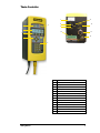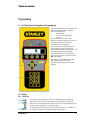
1
Assembly Technologies
Theta Controller User Manual
Software Version QC1-1.0.1
Important Safeguards
For your protection, please read these instructions completely, and keep this manual for future
reference. Carefully observe and comply with all warnings, cautions and instructions placed on the
equipment or described in this manual.
© 2008 THE STANLEY WORKS, ALL RIGHTS RESERVED
www.StanleyAssembly.com
ThetaUser091008
User Manual
Contents
Getting Started ...........................................................................................1
1.1
EC Directives ........................................................................1
1.2
Warnings and Cautions ........................................................1
1.3
Specifications, Layout and Display .......................................2
1.4
Installation Instructions .........................................................4
1.4.1
Theta Controller E-Stop Precaution...............................6
Programming..............................................................................................7
2.1
QA Theta Controller Navigation and Programming...............7
2.2
Display ..................................................................................7
2.2.1
Scroll Bar .......................................................................7
2.2.2
Dropdown ......................................................................8
2.2.3
Menu Tree .....................................................................8
2.2.4
Tabs ..............................................................................8
2.2.5
Character Scrollbar........................................................8
2.2.6
Run Display ...................................................................8
2.3
Faults....................................................................................9
2.4
Messages ...........................................................................10
2.5
Theta Controller Programming............................................11
2.5.1
Setup Menu: 1. Jobs....................................................12
2.5.1.1 Wizard Screens .......................................................13
2.5.1.2 Setup: Job Tab ........................................................16
2.5.1.3 Setup: Manage Button (Job) ....................................17
2.5.1.4 Setup: Step Button...................................................18
2.5.1.5 Setup: Manage Button (Step) ..................................20
2.5.1.6 Setup: Exit ...............................................................21
2.5.2
Setup Menu: 2. Communications.................................21
2.5.3
Setup Menu: 3. Other ..................................................22
2.5.4
Setup Menu: 4. Restore Factory Defaults....................27
2.5.5
Service.........................................................................28
2.5.5.1 Tool..........................................................................28
2.5.5.2 Controller .................................................................29
2.5.6
Analyze........................................................................30
QPM DC Electric Tools ............................................................................33
3.1
Tool Specifications..............................................................33
3.2
Operator Protection ............................................................34
Repetitive Motion .......................................................................34
3.2.1
Hearing Protection .......................................................34
3.2.2
Vibration ......................................................................35
3.2.3
Breathing Protection ....................................................35
3.3
Tool Installation...................................................................35
3.3.1
Sockets and Adapters..................................................35
3.3.2
Suspension Devices ....................................................36
3.3.3
Cable Installation .........................................................36
3.4
QPM Tools..........................................................................37
ii
Theta Controller
3.4.1
Display and Multiple Function Button for Hand Held
Tools
37
3.4.2
MFB Mode ...................................................................37
3.4.3
Tool Memory................................................................37
3.4.4
Tightening Cycle Counters ..........................................38
3.5
Tool Operation ....................................................................38
3.5.1
Directional Control .......................................................39
3.5.2
Torque Reaction Devices ............................................39
3.5.3
Tool Temperature ........................................................39
3.5.4
Tool Status Lights........................................................39
3.5.5
Setting Torque, Angle, and Other Operating Parameters
40
3.6
Special Application Tools....................................................40
3.6.1
Exposed Gear Socket Tools ........................................40
3.6.2
Tubenut Nutrunners.....................................................40
Theta Controller Connections...................................................................41
4.1
Theta Controller Connections .............................................41
4.1.1
Theta Controller Power Cord .......................................41
4.1.2
Theta Controller Tool Connector .................................41
4.1.3
Theta Controller Serial Connector ...............................42
4.1.4
Theta Controller Input and Output Connector..............42
4.2
Assignable Input/Output Functions .....................................45
4.2.1
Input Descriptions ........................................................46
4.2.2
Output Descriptions .....................................................47
Glossary ...................................................................................................50
Appendix A – Controller Gateway ............................................................52
Appendix B – Torsion Compensation.......................................................53
Warranty...................................................................................................55
Contents
iii
Theta Controller
Getting Started
This manual is intended to promote proper and safe use and give guidance to owners, employers,
supervisors, and others responsible for training and safe use by operators and maintainers. Please
contact your Stanley Sales Engineer for further information or assistance on Stanley training or
assembly tool operations.
1.1 EC Directives
The QPM tightening systems are designed and built, in whole or in part, using the following
standards and or directives.
2006/42/EC Machinery Directive
Standard
EN292-1,2
EN14121-1
EN50178
EN60204-1
EN60745-1
Title / Description
Safety of Machinery - Basic Concepts
Safety of Machinery - Principles of Risk Assessment
Electronic Equipment for Use in Power Installations
Safety of Machinery, Part 1 - Electrical Equipment of Machines
Hand-Held Motor-Operated Electric Tools - Safety
89/336/EEC Electromagnetic Compatibility Directive
Standard
EN55011
EN61000-3-2
EN61000-3-3
EN61000-4-3
EN61000-4-4
EN61000-4-5
EN61000-4-6
EN61000-4-8
EN61000-4-11
EN61000-4-2
Title / Description
Conducted and Radiated Emissions
Current Harmonics
Voltage Fluctuation and Flicker
Radiated Immunity
Fast Burst Transients
Surge
Conducted Immunity
Magnetic Immunity
Voltage dips/interruptions
Electrostatic Discharge Immunity
Level 4: Contact Discharge 8 KV, Air Discharge 15 KV
1.2 Warnings and Cautions
The safety notices and warnings for protection against loss of life (the users or service personnel)
or for the protection against damage to property are highlighted in this document by the terms and
pictograms defined here. The terms used in this document and marked on the equipment itself
have the following significance:
Danger
Indicates that death or severe
personal injury will result if
proper precautions are not taken.
Indicates a general hazard. This
icon appears as a part of a
Danger, Warning, or Caution
notice.
Warning
Indicates that death or severe
personal injury may result if
proper precautions are not taken.
Indicates that eye protection
should be worn. This icon
appears as a part of a Danger,
Warning, or Caution notice.
Caution
Indicates that property damage
may result if proper precautions
are not taken.
Read and understand all the
safety recommendations and all
operating instructions before
operating tools and controllers.
Getting Started
1
User Manual
Indicates an electrical hazard.
This icon appears as a part of a
Danger, Warning, or Caution
notice.
Indicates an item of special
interest.
WARNING
To Avoid Injury:
•
Read and understand all the safety recommendations and all operating instructions before
operating tools and controllers. Save these instructions for future reference.
•
Train all operators in the safe and proper use of power tools. Operators should report any
unsafe condition to their supervisor.
•
Follow all safety recommendations in the manual that apply to the tools being used and the
nature of the work being performed.
•
Verify that all warning labels illustrated in this manual are readable. Replacement labels are
available at no additional cost from STANLEY ASSEMBLY TECHNOLOGIES.
Qualified Personnel
WARNING
To Avoid Injury:
•
Only allow suitably qualified personnel to install, program, or maintain this equipment and or
system.
•
These persons must be knowledgeable of any potential sources of danger and maintenance
measures as set out in the Installation, Operations, and Maintenance manual.
•
This product must be transported, stored, and installed as intended, and maintained and
operated with care to ensure that the product functions correctly and safely.
•
Persons responsible for system planning and design must be familiar with the safety concepts
of automation equipment.
1.3 Specifications, Layout and Display
Dimensions
Width:
6.0 in
152 mm
Height:
14.2 in
361 mm
Depth:
8.2 in
208 mm
15 lb
7.0kg
Weight:
Operating Conditions:
Temperature:
32 to 122 ºF (0 to +50 ºC)
Humidity:
0 to 95 % non-condensing
Power Source:
100 – 126 VAC, 50/60 Hz, 15 – 20A service or
207 – 253 VAC, 50/60 Hz, 10 – 16A service
Power Consumption:
Stand by:
Tool Motor Power:
Service Rating:
EC02/EC22
EC33/EC34
EC44/E45
EC55
Consumption
@ 115 VAC:
15A
15A
20A
---
@ 230 VAC:
10A
10A
10A
16A
Continuous kVA:
0.3
0.7
1
1.7
0.2 A (amperes)
Continuous:
2
1-2.5 kVA
Theta Controller
7
8
5
1
11
12
9
2
13
10
3
14
4
6
Item
1
Getting Started
Functional Description
Red, Green, Yellow LED's for Limits Evaluation
2
Display
3
Function Keys with Active Label Above
4
Cursor Keys with Center Button to Expand Lists
5
Maintenance Due and ATC Active LED's
6
Numeric Keypad to Enter Numbers or Select Options
7
Controller Label and Serial Number
8
Power Switch
9
Power Input
10
24 VDC Input/Output Connector
11
20A Fuse MDA-20 (P/N 21R201007)
12
Serial Connector for Laptop
13
Tool Connector
14
Serial Connector for Network Protocols
3
User Manual
1.4 Installation Instructions
WARNING
To Avoid Injury:
•
Always wear eye and foot protection when installing equipment.
•
Only use equipment and accessories specifically designed to operate with Stanley assembly
tools and use them only in the manner for which they are intended.
•
Do not install worn, damaged, or modified equipment that may be unsuitable for safe use.
•
Train all operators in the safe and proper use of power tools. Operators should report any
unsafe condition.
•
Store idle tools and accessories in a safe location accessible only by trained persons.
•
Disconnect power source (air, electricity, etc.) from tool prior to making adjustments, changing
accessories, or storing.
•
Prior to operation, always check and test tools and accessories for damage, misalignment,
binding or any other condition that may affect operation. Maintenance and repair should be
performed by qualified personnel.
•
Do not operate tools in or near explosive environments or in the presence of flammable liquids,
gases, dust, rain or other wet conditions.
•
Keep the work area clean, well lit and uncluttered.
•
Keep unauthorized personnel out of the work area.
DC Electric Tools & Controllers:
•
Install tools in dry, indoor, non-flammable, and non-explosive environments only – Humidity: 0
to 95% non-condensing and Temperature: 32 to 122 ºF (0 to +50 ºC).
•
Installation, maintenance and programming should be performed by qualified personnel.
Follow all manufacturer installation instructions and applicable regulatory electrical codes and
safety codes.
•
Tool and controller plugs must match the outlet. This equipment must be earth grounded.
Never modify a plug in any way or use any adaptor plugs.
•
Avoid body contact with electrically energized surfaces when holding a grounded tool.
•
Prior to connecting a power source, always ensure the tool or controller is turned off.
•
Limit controller access to trained and qualified personnel. Lock controller cabinets.
WARNING
To Avoid Injury:
•
•
•
Install modules in dry, indoor, non-flammable, and non-explosive environments only.
Qualified personnel should perform installation and programming. Follow all manufacturer
installation instructions, applicable regulatory electrical codes, and safety codes.
Limit module access to trained and qualified personnel. Lock module cabinets.
WARNING
ELECTRICAL HAZARD
To Avoid Injury:
•
•
•
•
•
4
Install modules in dry, indoor, non-flammable, and non-explosive environments only.
Do not use this product near water, for example near a washbowl, wet basement, or the like.
This product should be located away from heat sources such as radiators or other devices that
produce heat.
This product should not be subjected to vibration or shock or in close contact with water or
other liquids.
To minimize electrical interference, place the module as far away from possible sources of
electrical noise, such as arc welding equipment.
Theta Controller
Plinths connect to each other with four 10-32 machine screws through openings on the top and
right side to threaded openings on the bottom and left side. When mounting plinths are placed next
to each other the center to center distance between the mounting holes in different plinths is 2"
(50.8 mm). When mounting plinths are place one above another the center to center distance
between the mounting holds in different plinths is 6" (152.4 mm).
1.
Install the Theta Controller either directly to the wall or to an optional mounting plinth.
2. Fasteners through four mounting holes secure plinths to a wall or surface. Plinths can be
connected using 10-32 threaded holes on the bottom and left side and through holes on the top and
right side.
3. Make sure the bolts of the barrel-latches [5] on the plinth are retracted. Place the lower flange
of the Theta controller [1] into the lip [2] on the plinth.
4. Align the slot [3] in the flange with the lower mounting-pin [4] on the plinth while placing.
Rotate the top of the controller back towards the plinth.
5. Place the openings on the upper flange of the controller [6] over the upper mounting pins [7]
on the plinth. Release the bolts on the barrel-latches [5] making sure the bolts enter the two barrels
[8] on the controller.
6.
Connect the Theta Controller to a power source.
7.
Connect the tool cable to the Theta controller and press the power switch on the controller.
8. The controller will display a list of languages after
the first boot up from the factory. Press the up or down
arrows to select the appropriate language for the region,
then press the Enter key to save the selection. The
controller will display its run screen, indicating it is
ready for programming and operation.
Getting Started
5
User Manual
1.4.1 Theta Controller E-Stop Precaution
WARNING
INTEGRATED E-STOP CIRCUIT NOT PRESENT
To Avoid Injury:
When a Theta controller connects to a tool where a fault can result in personal injury or substantial
damage to property, an E-stop circuit is required. An E-stop circuit must be created in the external
power supply line.
6
Theta Controller
Programming
2.1 QA Theta Controller Navigation and Programming
The Theta controller’s three navigation and
input areas facilitate menu navigation,
selection and data input:
•
Menu buttons
•
Arrows and Toggle button
•
Keypad
Labels for the four interactive menu
buttons [1] change with menu selection. If
the label is blank, the button has no
function for the current display.
The up/down arrows [2] navigate menu
and character selections; the left/right
arrows enable backspace and space, as well
as navigate between tabs. The toggle
button [3] switches between modes and
selects/accepts choices (synonymous with
OK menu button).
The numeric keypad [4] facilitates data
input and menu selection (where
applicable) and job/step selection when
enabled.
2.2 Display
2.2.1 Scroll Bar
A scroll bar appears when more items are available than space within the
display allows. The up arrow [1] and down arrow [3] direct scrolling. The
black/white scroll bar [2] indicates which list items are currently displayed. No
scroll bar means all items are currently displayed.
To navigate between menu items, use the up/down arrows or, if available, use
the keypad to identify the corresponding menu item number.
Programming
7
User Manual
2.2.2 Dropdown
A dropdown [1] arrow appears to the right of menu items with multiple
choices. To view these choices, first select the menu item using the
up/down arrows or use the keypad to identify the corresponding menu item
number. Then, use the toggle button to expand the dropdown. The up/down
arrows scroll through the choices and the toggle button selects/accepts the
highlighted choice.
2.2.3 Menu Tree
A menu tree [1] appears beside related menu items.
2.2.4 Tabs
Tabs [1] appear at the top when multiple menu selections exist.
To navigate between tabs, use the left/right arrows. The active
tab is white; inactive tabs are grey.
2.2.5 Character Scrollbar
This scrollbar enables adding: a-z, A-Z, 0-9, space, _, -, &, *, $, #, @, !, and a
period (language and/or field determines character availability). The up arrow [1]
and down arrow [3] direct scrolling with the active character [2] displayed
between. Use the Theta Controller’s up/down arrows to scroll through character
choices. The left arrow backspaces. The right arrow moves one position to the right
to input next character. Push toggle button or OK menu button to accept entry.
The following screens contain the character scrollbar option: Job (Name), Step
(Name), System Name (General), and System (Users).
2.2.6 Run Display
Displays last torque reading and units [2]
when a tool is connected. Icons [1] identify
controller events (see list below). Specifies
target bolt count in active job [3]. The run
screen displays unless other programming
functions [4] are in use. The active job [5].
The display background color in normal
operation is white. After an OK fastening
cycle, the display background color will
change to green for 2 seconds, then revert
back to white for the next cycle. After a
NOK fastening cycle, the display
background color will change to red for 2
seconds, then revert back to white for the
next cycle. The display background color
will turn red in the event of a fault; see
section 2.3
If the keypad mode is set to Job Select, press a number key
corresponding to a programmed Job. A Job window will
pop up and allow you to enter a number. Press the OK
button to switch the controller operation to the selected Job
number. See section 2.5.3 to select keypad mode.
8
Theta Controller
Shutoff Codes on the display indicate why a tightening cycle shutoffs other than upon completion
of tool strategy.
Run Display
Code
Description
Tightening time exceeds programmed Cycle Abort time value
TIME
STOP
Spindle stopped by either the operator or other device
125%
Spindle stopped due to torque achieving greater than 125% torque limit for the spindle
FAULT
Precedes a fault described in section 2.3
STALL
Spindle in stall status
CAN
Can occur during a tightening cycle when a spindle firmware update is in progress
Theta Controller Icons
Icon
Status
Locked
Unlocked
Busy/working
Fault, system not operable
Force on or off
User Entered Password
Stop Tool Operation,
(press the trigger for an indication
of what is causing the tool Stop)
Description
Password required to make changes
Changes possible, automatically re-locks in time
Wait
Check the run screen for Fault message
Identifies an input/output forced on or off
This icon appears next to the user, in the User list,
that has entered their password and unlocked the
box.
Undefined Job – The selected Job is not
programmed to run a tool, select another Job or
program the currently selected Job.
Network Protocol – The plant control system is
issuing a Stop via a network protocol. Wait for the
protocol to remove the Stop command.
Error Proofing - Bolt count has been met, reset with
a Job Reset input.
Stop Issued - An Input is disabling the tool, remove
the Stop input.
Reset Reject - is enabled and active, reset the reject
by pressing the MFB.
Invalid Job – The selected Job is wrong based on
the validation inputs.
System Initializing – the controller is booting up,
please wait.
Cycle Lock-out – The Cycle Lockout timer is
active, wait for it to reset.
2.3 Faults
The display background color in normal operation
is white. In the event of a fault, the display
background becomes red and the fault description
appears on screen. The background color reverts
to white only when the fault is cleared.
Programming
9
User Manual
Overcurrent Fault!
There are two things that can cause this hardware fault:
a)
GFI – the Ground Fault Interrupter has exceeded its
current trip point. A current detector monitors the
current through the 3 phases of the motor and asserts this
fault when the total current applied to the tool does not
equal the total current returned from the tool. All phases
are turned of immediately to protect the controller from
shorts at the tool end.
b) Total Current – the controller software limits the current
applied to any tool based on what the tool can handle.
This fault is asserted if there is a short at the tool end and
the total current applied is greater than allowed.
Logic Voltage Fault!
The controller monitors the +5VDC, -5VDC and +12VDC of its
onboard Power Supply. This fault is asserted when those
voltages fall outside of nominal range.
Position Feedback Fault!
The controller is constantly monitoring the “resolver” zero and
span points and asserts this fault if they go outside specification.
Transducer Span Fault!
This fault is asserted when the transducer zero point has shifted
far enough to prevent a full scale reading from the transducer.
Temperature Fault!
This fault is asserted when the tool temperature detector has
reached the temperature limit set by the Temperature Limit
parameter. It resets after detected temperature has dropped by
5°C
Unrecognized Tool!
The controller is communicating to the tool but does not
recognize the model number written in the tool memory board.
Tool Communications!
The controller is not communicating to a tool.
Transducer Current Fault
Transducer current has fallen outside nominal values. For “EC”
series tools that is 4.16 mA +/- 75% ( 1 to 7mA).
Transducer Zero Fault!
The transducer zero point has shifted too far for the controller to
compensate. These points are visible on the controller
diagnostics screen under Analyze.
Unsupported Tool!
The wrong tool type has been connected to the controller. The
Theta controller cannot run the tool that is connected.
2.4 Messages
Messages appear on the screen when certain non-critical conditions exist that asserts the warning.
They may appear on any screen at any time.
Communication Fault
Used for Toyota Protocol only. Controller has lost
communications to the PI box.
Count Fault
Used for Toyota Protocol only. Controller and PI box have a bolt
count mismatch.
Program Fault
Used for Toyota Protocol only. More tightening cycles were
performed than the PI box expected.
Tool Update Failed
Controller failed to update the tool configuration.
Nothing to Configure!
The parameter selected has nothing to configure.
10
Theta Controller
2.5 Theta Controller Programming
WARNING
EXCESSIVE TORQUE CONDITION
To Avoid Injury:
•
Only trained and qualified personnel should program controllers.
•
Never set control limits above the maximum rating of the tool.
•
Setting control limits above the maximum rating of the tool can cause high reaction torque.
•
Always test for proper tool operation after programming the controller.
The controller uses three main menus to display information and enable programming:
• Setup menu
• Service menu
• Analyze menu
To begin programming a tool strategy on the Theta, press the SETUP menu button. The list of
setup functions will appear.
1. Jobs – this is where the tool strategy programming is performed, such as torque and speed
parameters.
2. Communications – this area is where the Serial port options are programmed.
3. Other – this area has the parameters for all other features on the Theta. They include setting up
system level parameters, users and passwords, assigning I/O, and tool functions.
4. Restore Factory Defaults – this area deletes all prior programming, stored fastening cycle data,
and statistics and sets the controller back to factory defaults.
To enter an area, simply press the corresponding numbers on the keypad or us the up and down
buttons to highlight the area and press the Enter key.
Icon Legend
Icon Description
Menu Buttons
Press to activate menu option noted above button.
Left/Right Arrow Keys
Navigate tabs as well as backspace and space.
Up/Down Arrow Keys
Programming
Navigation
Scroll through menu selection and character selection.
Toggle Button
Selects option for data input, accepts changes.
Numeric Keypad
Data input and, when applicable, menu selection. Can
be used for job selection when enabled to do so.
11
User Manual
The left column shows the currently defined Theta Controller settings and menu choices. The
Options Screen column shows options for each selection. Screen navigation options appear above
each screen.
Default Screens
Options Screen
NOTE:
Programming changes are stored after exiting current menu and returning to run screen.
Job Reset resets bolt count back to zero.
2.5.1 Setup Menu: 1. Jobs
The Setup menu programs the controller to operate a spindle or tool. Jobs control tool operation
for tightening a fastener and consist of one TC/AM (Torque Control, Angle Monitor) Step, with
up to three optional Smart Steps. Most controllers will operate with a single Job and Step. Users
must have ADMINISTRATOR or SETUP access in order to modify Job settings. This includes
Wizard, Manage and Step parameters.
If a tool is attached and no jobs are programmed the Wizard automatically appears after selecting
Jobs. The Wizard can setup a Job for simple or complex tightening cycles using the optional Smart
Steps.
If no tool is attached, or if at least one Job exists already, the Job menu will appear.
The Wizard will be discussed first and then the Job setup afterwards.
12
Theta Controller
2.5.1.1 Wizard Screens
Wizard Screens
Options Screen
The Wizard assists with programming the controller to assign a Job which consists of one
Audit Step with optional Smart Steps. To function, the Wizard requires a tool to be connected.
The Wizard automatically appears when there are no configured Jobs or when Jobs are added.
The Wizard presents programming parameters about the FINAL strategy desired, and then it
will give a list of modifiers for that strategy. These modifiers are explained further down in
this section.
Strategy – TORQUE (TC/AM) is the only
strategy the Theta controller supports. There
are no other options for this parameter.
Units – the Theta supports the following
operating units:
NM, Newton Meters
FTLB, Foot Pounds
INLB, Inch Pounds
INOZ, Inch Ounces
KGM, Kilogram Meters
KGCM, Kilogram Centimeters
NCM, Newton Centimeters
Thread Direction – for tightening a right hand
fastener use CW, clockwise. Use CCW,
counter-clockwise for left hand fasteners.
To modify, select using the up/down arrow keys then press the Toggle button. After all
parameters/ selections / options are finished, press the NEXT interactive menu button to
advance through the Wizard. Repeat for subsequent windows.
Pressing the CANCEL interactive menu button at any time to stop Wizard operation.
Use the keypad to enter the desired values for
High Torque, Low Torque and Speed.
Programming
High Torque – By default, the Wizard uses
the maximum torque for the connected tool.
Low Torque – The Wizard uses zero as the
low torque limit of the strategy.
Speed – The Wizard uses the maximum
speed of the connected tool.
13
User Manual
Wizard Screens
Options Screen
Press the Prev button to move back to previously programmed screens within the Wizard.
The final TC/AM step is now defined. The Wizard uses the median value, between the High
and Low Torque parameters, as the Target Torque. It also calculates and programs other
parameters automatically, including Snug Torque, Threshold Torque, Statistical Torque, and
High Angle Bailout. Change these values after saving your Wizard programming if desired.
Next, select the modifiers specific to your application. Option screens appear for each specific
modifier chosen. The Wizard makes assumptions and calculates specific values, modify these
values if necessary..
Wobble, Slow Seek and Self Tap are Smart
Steps that can be added to the beginning of the
tool strategy. These modifiers only exist
when an audit step exists; they cannot be
programmed as steps unto themselves.
ATC (Adaptive Tightening Control) controls
tool inertia toward the end of the tightening
cycle. This allows for more consistent
fastening.
Wobble is an Angle Control / Torque
Monitoring strategy in the opposite direction
for which the final tool strategy is
programmed. This allows the fastener threads
to align with the locking device threads before
a standard forward rotation and high speed are
applied, thereby preventing cross-threads. If
selected, this will be the first step in the tool
strategy.
Wobble Options include:
Angle Target – The number of degrees of
rotation the socket will turn during this step.
Speed – The speed of the tool during this step.
Max Torque – The maximum allowed torque
during this step. A low value is calculated by
the Wizard to detect cross-threads.
Slow Seek is an Angle Control / Torque
Monitoring strategy in the same direction for
which the final tool strategy is programmed.
This allows the flats of the socket to align
with the flats on the fastener before a standard
forward rotation and high speed are applied.
Using Slow Seek as a first step also allows for
cross-thread detection. If selected, this is the
first step AFTER Wobble. If Wobble is not
selected, this is the first step in the tool
strategy.
14
Theta Controller
Wizard Screens
Options Screen
Angle Target – The number of degrees of
rotation the socket will turn during this step.
Speed – The speed of the tool during this step.
Max Torque – The maximum allowed torque
during this step. A low value is calculated by
the Wizard to detect cross-threads.
Self Tap is an Angle Control / Torque
Monitoring strategy in the same direction for
which the final tool strategy is programmed.
This Smart Step allows the tool to compensate
for a high prevailing torque application. If
selected, this step follows the Slow Seek step
and just prior to the audit step.
Angle Target – The number of degrees of
rotation the socket turns during this step.
Snug Torque – Angle measurement, for the
target angle, starts at this torque.
Speed – The speed of the tool during this step.
Max Torque – The maximum allowed torque
during this step.
ATC (Adaptive Tightening Control) is not a
strategy or a step. It is an algorithm that
modifies the tool’s speed as the torque rises.
Select this, instead of a downshift, as an
option to increase tool capability.
There are no options with this selection. The
values are calculated automatically.
Press the Finish button to complete the
Wizard.
The Job Tab screen appears. This allows
parameter changes to be made prior to saving
Wizard programming. To save, press the
EXIT interactive menu button.
Press the YES interactive menu button to save
changes. This saves the parameters and opens
the Run screen.
Programming
15
User Manual
2.5.1.2 Setup: Job Tab
Jobs are required to setup a tool strategy. Inputs and Triggers are used to select specific Jobs with
different tool strategies including Error Proofing (bolt counting). Program the Job parameters
according to the integration strategy desired; then program the Step(s) to create the desired tool
strategy.
Job Tab Screens
Options Screens
Tool settings apply to all Steps.
Select Jobs by pressing the SETUP button on
the run screen.
Press 1 or with the Jobs menu item
highlighted, press the Enter key.
or
Name – Name Job to define the operation
performed (15 character limit). Use the
up/down arrows to spell with letters or use the
numeric keypad.
Auto Reset Job – Yes resets the Job
automatically after the fastener count has
been met. The tool will not disable with Error
Proofing enabled. No requires an Input or
Trigger to Reset the Job. The tool disables
with Error Proofing enabled. If Error Proofing
is disabled, the tool is always enabled but will
not count higher than the target value.
Enable Error Proofing – Yes causes the tool to disable after the accumulated fastener count
equals the target fastener count for the job, unless Auto Reset Job is set to Yes. A Trigger or
Input is required to Reset the Job and set the accumulated count to zero.
No keeps the tool enabled even after the Job’s target count is met. The count will not increase
beyond the Batch Count value.
Batch Count – This is the number of fasteners the Job is required to count. Zero is not allowed.
The maximum is 99.
Units – the Theta supports the following operating torque units:
NM, Newton Meters
FTLB, Foot Pounds
INLB, Inch Pounds
INOZ, Inch Ounces
KGM, Kilogram Meters
KGCM, Kilogram Centimeters
NCM, Newton Centimeters
Each Job does not have to use the same operating torque units as the other Jobs.
16
Theta Controller
Job Tab Screens
Options Screens
Thread Direction – for tightening a right hand fastener use CW, clockwise. Use CCW,
counter-clockwise for left hand fasteners.
Threshold Torque – The torque level during the tightening cycle when the In Cycle Output
transitions high. Data is not printed, stored or available to eTB, unless Threshold Torque is
exceeded during the tightening cycle. A good starting point is 20% of Target Torque.
Disassembly Speed – The speed of the tool during (Reverse) operation in RPM (revolutions per
minute).
Disassembly Acceleration – The rate the tool gets up to Disassembly Speed in RPM/s
(revolutions per minute per second).
Cycle Lock-Out – This is a timer, in seconds, that activates after the tool has reached its target.
While active it disables the tool.
Press Exit to save changes and return to the Run screen.
Press Manage to Add, Delete, Copy or Paste Jobs. See section 2.5.1.3 for further information.
Press Step to setup the parameters of the step(s) inside the selected Job. See section 2.5.1.4 for
further information.
2.5.1.3 Setup: Manage Button (Job)
Manage Button (Job) Screens
Options Screen
Manage enables active job settings to be added, deleted, and/or copied to the clipboard and
pasted.
Add – Adds a Job to the controller. If a tool
is attached the Wizard will begin for easy
setup of the Job parameters. If a tool is not
attached the Jobs tab will appear for manual
parameter setup.
Jobs do not have to be added sequentially. A
Job can be added before, or after, the one that
is selected. Jobs will be renumbered
automatically after being added. Make a
selection and press OK to add a Job, or
Cancel to not add a Job.
Delete – Deletes the selected Job from the
controller. This cannot be recovered once
deleted.
Copy – This will copy the selected Job and its
associated Steps to the Clipboard.
Programming
17
User Manual
Paste – Overwrites the selected Job with the
values of the Job residing in the Clipboard.
2.5.1.4 Setup: Step Button
Step Button Screens
Options Screens
Step settings only affect the selected Job. There can be only one audit step per Job. In the
Theta, that audit step is a Torque Control / Angle Monitor (TC / AM) strategy. The audit step
can have Smart Steps associated with it. Without the audit step the Smart Steps are deleted.
Each step is represented by its own tab. Use the left or right arrow keys to select the tabs/steps
to modify them.
Name – Provides an identifier for the step.
Use the up and down arrows to write a name
using the alphabet. Use the number keypad
for numbers.
Torque Target – The torque at which the
controller shuts off the tool (required for this
step). Should be greater than Low Torque and
lower than High Torque.
High Torque – The maximum peak torque for
an acceptable tightening cycle. If the actual
torque exceeds this limit the tightening cycle
will be flagged as NOK and the RED LED on
the front panel and the tool will illuminate.
Required for this step. Must be greater than
Torque Target and less than or equal to the
rated torque marked on the tool.
Low Torque – The minimum peak torque for an acceptable tightening cycle. If the actual
torque does not reach this limit the tightening cycle is flagged as NOK and the YELLOW LED
on the front panel and the tool will illuminate. Required for this step. Must be less than the
Torque Target.
Snug Torque – The point in this step when the controller begins to monitor the tool’s output
angle. Should be greater than 0 and less than Low Torque. A value of 50% of Torque Target is
a good starting point.
High Angle – The maximum peak angle for an acceptable tightening cycle. If the actual angle
exceeds this limit the tightening cycle is flagged as NOK and the RED LED on the front panel,
and the tool, will illuminate. Required for this step. Must be greater than Low Angle. Units
are degrees of rotation.
Low Angle – The minimum peak angle for an acceptable tightening cycle. If the actual angle
does not reach this limit the tightening cycle is flagged as a NOK and the YELLOW LED on
the front panel and the tool will illuminate. Must be less than High Angle. Units are degrees of
rotation.
Angle Bailout – Determines when to stop the tool on angle. Should be set equal to or above
High Angle. Units are degrees of rotation.
Downshift Mode – Selects the type of spindle inertia control toward the end of a tightening
18
Theta Controller
Step Button Screens
Options Screens
cycle.
Disabled – Does not reduce the speed of the motor.
Manual – Reduces the tool speed to a specific value (Downshift Speed) when a specific torque
value (Downshift Torque) is achieved during the tightening cycle. Speed units are RPM,
Torque is in torque units.
ATC – Enables the Adaptive Tightening Control algorithm to slow the tool speed as the torque
rises.
The default values can be modified for when the algorithm starts (ATC Starting Torque), when
it ends (ATC Ending Torque) and what the tool speed is after the algorithm ends (ATC Ending
Speed). The torque units are percent of Target Torque. The speed values are percent of Speed.
Soft Stop – This controls how the tool is turned off AFTER reaching target torque. This is
designed as an ergonomic benefit to ease operator discomfort with direct-drive tools. If No is
selected the tool will simply de-energize and coast to a stop.
If Yes is selected, the tools current will be removed for the time specified in Current Off Time,
then reapplied for the time specified in the Current Hold Time, then it will ramp to zero over
the time specified in Current Ramp Time. Units are in seconds.
Speed – The velocity of the output of the tool during this step before any Downshift Mode
activates. Units are RPM. Required for this step. Must be greater than 0.
Power – The maximum power available to the tool to perform the tightening cycle. Units are
percent of maximum rated torque of the tool. Required for this step, should not be less than
100%.
Acceleration - The rate the tool gets up to Speed in RPM/s (revolutions per minute per second).
Required for this step. Should be greater than 1000 RPM/s.
Abort Timer – Stops the tool when the time has elapsed from the start of the step. Required for
this step. The value should be long enough to complete the tightening cycle during this step.
Once the audit step has been created, Smart Steps can be added. Smart Steps allow you to
modify the tool strategy BEFORE the audit step. See section 2.5.1.5 for adding Smart Steps.
When finished modifying the tool strategy step(s), press the EXIT key, save the changes and
return to the run screen. See Section 2.5.1.6.
Programming
19
User Manual
Step Button Screens
Options Screens
2.5.1.5 Setup: Manage Button (Step)
Manage Button (Step) Screens
Options Screen
Manage enables step settings to be added, deleted, and/or copied to the clipboard and pasted.
Add – Allows the addition of Smart Steps.
The Smart Step choices are Wobble, Slow
Seek and Self Tap. When added, they are
inserted into the correct position before the
audit step (Smart Step sequencing cannot be
altered). Wobble always occurs first followed
by Slow Seek and Self Tap, then the audit
step. Smart Steps are not required to run a
tool strategy, however, they may help. Add
and modify the appropriate Smart Step(s) for
the application. See section 2.5.1.1 for a
description of the Smart Steps.
Delete – Allows the deletion of the selected
step from the tool strategy.
Copy – Copies the selected step to the
clipboard.
Paste – Overwrites the selected step with the
values in the clipboard. The type of
information in the clipboard must match the
step into which it will be pasted. Smart Step
values cannot be pasted into audit steps and
vice versa.
20
Theta Controller
2.5.1.6 Setup: Exit
Exit Screens
Options Screen
Programming changes are stored after exiting the current menu.
2.5.2 Setup Menu: 2. Communications
Communication Screens
Options Screen
This area changes the setting of the serial Communications ports on the bottom of the Theta.
Users must have COMMUNICATIONS, SETUP or ADMINISTRATOR access level to
modify values in this area.
ETB – This selection allows the controller to
communicate to the Controller Gateway
software on a PC. See Appendix A.
Programming
The Theta controller has two serial
communication ports. COM Port 1 must be
used for ETB. COM Port 2 can be used for
error proofing or data collection protocols.
Toyota – an error proofing protocol used in
handheld tool applications in Toyota
facilities.
OPEN – an error proofing / data collection
protocol used in tool applications in Ford and
Honda facilities. This protocol can be used
by others as it does not take special
equipment like the Toyota protocol.
21
User Manual
2.5.3 Setup Menu: 3. Other
Other Screens
Options Screen
This area has the parameters for all other features on the Theta. They include setting up system
level parameters, users and passwords, assigning I/O, and tool functions. Each category is
represented by its own tab. Use the left or right arrow keys to select the tabs/category to
modify them.
Users must have ADMINISTRATOR or SETUP access level to modify values in this area.
General Tab
Name – This gives a name to the controller so
it can be distinguished from other Theta
controllers on the same plant floor.
Keypad Mode – The keypad on the face of the
controller can be used to select Jobs (Job
Select) to run while in the run screen. Or this
function can be (Disabled).
Use the right arrow to move to the next tab or press the EXIT key, save the changes and return
to the run screen. See Section 2.5.1.6.
Users Tab
To add a user, press the Manage button.
The Theta controller can have 8 users
assigned, each with unique passwords. The
passwords can be any length up to 16
characters and can be made up of any
characters that can be created using the up
and down arrows and numbers on the keypad.
Adding users is a 3 step process. First add the
user and give them a User Name. Press OK.
If users are assigned, one of them must be an
Administrator.
If the lock icon appears, the controller is
password protected. The controller
automatically re-locks the system after 15
minutes.
22
Then select the user you just added in the list,
Theta Controller
Other Screens
Options Screen
press the Manage key then Change Password.
If this is the first time adding a password
leave the Old password blank, otherwise key
in the old password, scroll down and create a
New password and Verify you have the
correct password by typing a second time.
Press OK.
Now change the access level of the user you
just created by pressing the Manage button
again, then Change Access.
One user has to be an Administrator. If other
users added are not, then select NO.
The Administrator has to log in to change
access for a user. Once the Administrator has
logged into the controller it is unlocked. The
unlocked icon will appear in the upper left
hand corner of the screen.
Select the Access level you wish to give to the
selected user. NONE does not allow them
access to the level; LOCAL will allow them
access, on the keypad, to that level. Each
access is exclusive of the other. You must
assign to users each access level that applies
to them.
Administrator gives the user full access to the
controller. They can do anything the other
access levels can do plus restore factory
defaults and add users.
Setup - Users at this level can modify all
parameters in the Job and Communications
areas. They may modify parameters under
the Input, Output and Trigger tabs in the
Other area.
Tool – Users at this level can modify
parameters under the Tool tab in the Other
area, as well as set Preventive Maintenance
Threshold and reset the PM and Cycle
counters in the SERVICE menu.
Diagnostics. – Users at this level can force
Inputs or Outputs ON or OFF and REMOVE
forces in the I/O tab of ANALYZE.
Communications – Users at this level can
modify the serial port settings.
Press OK.
To Delete a user press the Manage key and
then Delete. You will be asked “Are You
Sure?” If you are, press OK. It will ask for
the Administrator password. Once entered
the user will be deleted.
Press Ok,
Programming
23
User Manual
Other Screens
Options Screen
Use the right or left arrow to move to the next tab or press the EXIT key, save the changes and
return to the run screen. See Section 2.5.1.6.
OUTPUTS tab
The 24 VDC connector has pins 7 through 14
designated as Outputs from the controller.
The pin assignments are selectable on this tab.
Use the up or down arrows to select the pin
you wish to assign, then press the Enter key.
A list of available output elements will
display. See Section 4.2 for the complete list
and their descriptions. Scroll the list and
choose the element you wish to assign to the
selected pin. Press the Enter key
An Output element can be assigned to more
than one pin.
The selected Output element must then be
configured. See section 4.2 for configuration
options and their descriptions. Press the
CONFIG button to configure the selected
output element. After modifying press the
BACK button.
Use the right or left arrow to move to the next tab or press the EXIT key, save the changes and
return to the run screen. See Section 2.5.1.6.
INPUTS tab
The 24 VDC Connector has pins 3 through 6
designated as Inputs to the controller. The pin
assignments are selectable on this tab. Use
the up or down arrows to select the required
pin, then press the Enter key. A list of
available Input elements displays. See
Section 4.2 for the complete list and their
descriptions. Scroll the list and select the
element to assign to the selected pin. Press
the Enter key
An Input element can be assigned to more
than one pin.
The selected Input element must then be
configured. See section 4.2 for configuration
options and their descriptions. Press the
CONFIG button to configure the selected
Input element. After modifying press the
BACK button.
24
Theta Controller
Other Screens
Options Screen
Use the right or left arrow to move to the next tab or press the EXIT key, save the changes and
return to the run screen. See Section 2.5.1.6.
TRIGGERS tab
See Section 3.4.2 for an explanation of the
selectable items.
Tap Action – Defines the operation when the
MFB on the tool is tapped (pressed quickly).
Hold Action – Defines the operation when the
MFB on the tool is held for 1 second.
Start Input – Defines which inputs are
required to start the tool. In all cases, the 24
VDC Start input is always available to start
the tool.
Any – Either the tool trigger or tool push-tostart switch will start the tool.
All – Requires that both the tool trigger and
the tool push-to-start switch must be activated
to start the tool.
Lever – Only the trigger on the tool will start
the tool.
PTS – Only the push-to-start switch on the
tool will start the tool.
None – Neither the tool trigger nor the tool
push-to-start switch will start the tool.
Use the right or left arrow to move to the next tab or press the EXIT key, save the changes and
return to the run screen. See Section 2.5.1.6.
LIGHTS tab
Sets the time the pistol tool headlights remain
on, in seconds, after the trigger is pressed.
Programming
25
User Manual
Other Screens
Options Screen
Use the right or left arrow to move to the next tab or press the EXIT key, save the changes and
return to the run screen. See Section 2.5.1.6.
TONES tab
The alarm in the tool handle can emit
different tones based on the status of the
tightening cycle. Choose an Accept Tone for
an OK tightening cycle and a Reject Tone for
a NOK tightening cycle.
Play – previews the tone selected.
Stop – stops playing the tone selected.
Use the right or left arrow to move to the next tab or press the EXIT key, save the changes and
return to the run screen. See Section 2.5.1.6.
TOOL tab
Values modified under this tab are saved to
the tool not the controller. Users must have
TOOL or ADMINISTRATOR access level to
modify values here.
PM Limit – When the PM Counter in the tool
exceeds this threshold, the preventive
maintenance LED on the front panel
illuminates indicating it is time to perform
maintenance on the attached tool.
Temperature Limit – The threshold, in
degrees Celsius, when the tool will shut off.
This is caused by excessive duty cycle on the
tool.
Torsion Factor – See Appendix B for an
explanation of this parameter and how to
determine a correct value. Otherwise leave at
the default of zero.
Requires Arming – Forces the Tap Action on
the MFB to Arm. See section 3.4.2. Tubenut
tools require arming as a factory setting.
26
Theta Controller
Other Screens
Options Screen
Use the right or left arrow to move to the next tab or press the EXIT key, save the changes and
return to the run screen. See Section 2.5.1.6.
REGIONAL tab
Select the language for your region of the
world.
Use the right or left arrow to move to the next tab or press the EXIT key, save the changes and
return to the run screen. See Section 2.5.1.6.
Clock tab
The Theta has a real time clock which must
be set manually.
Time – format is hh:mm;ss, where h is hour,
m is minute and s is seconds. The format for
hour is military or 24 hour clock, rather than
12 hour clock with a.m. and p.m.
Date – format is mm / dd / yyyy, where m is
for month, d is for day and y is for year.
Use the left arrow to move to the next tab or press the EXIT key, save the changes and return
to the run screen. See Section 2.5.1.6.
2.5.4 Setup Menu: 4. Restore Factory Defaults
Restore Factory Defaults Screens
Options Screen
Restores all values for all parameters to their
factory default settings. This is good for
starting fresh with a controller that is in an
unknown programmed state. Users must have
the ADMINISTRATOR access level to
restore factory defaults.
Programming
27
User Manual
2.5.5 Service
2.5.5.1 Tool
Tool Tab Screens
Options Screen
The Service area presents information about the tool and controller. Users must have TOOL or
ADMINISTRATOR access level to modify any parameters here.
TOOL
All of the tool’s parameters are stored in the
tool memory board in the handle of the tool.
This area reads or writes those values on the
tool memory board, not in the controller.
ABOUT tab
This tab displays information about the tool
currently attached to the controller. None of
the fields are editable except the Serial value.
IF there is no serial number in the tool, you
are allowed to enter one into the tool, one
time only.
Use the right or left arrow to move to the next tab or press the EXIT key, save the changes and
return to the run screen. See Section 2.5.1.6.
COUNTERS tab
All three counters count up at the same time after
each OK tightening cycle.
Odometer – Cannot be reset. Indicates the total
number of OK tightening cycles the attached tool
has performed over its lifetime.
PM Counter – Causes the preventive maintenance
LED on the front panel, and the tool, to illuminate
when this value exceeds the PM Threshold value.
Trip Counter – This counter can be used to count
the number of OK tightening cycles between
resets.
Use the RESET button to reset, back to zero, either
the PM Counter or the Trip Counter.
28
Theta Controller
Tool Tab Screens
Options Screen
Use the right or left arrow to move to the next tab or press the EXIT key, save the changes and
return to the run screen. See Section 2.5.1.6.
CAL tab
Nominal Cal – This is a calculated value
based on the torque output of the motor, the
gear ratios and efficiencies. This is a
reference value only, it can not be modified.
Torque Cal – This is the specific torque
calibration value for the tool. Enter the new
calibration value for the tool after performing
a lab certification. This value should not
deviate from the Nominal Cal value by more
than 20%.
Press EXIT when finished modifying the
value.
2.5.5.2 Controller
Controller Tab Screens
Options Screen
CONTROLLER
ABOUT tab
This tab displays information about the
controller. These values are read only unless
blank. The Model and Serial fields can be
written to once.
Programming
29
User Manual
2.5.6 Analyze
Analyze Screens
Options Screen
ANALYZE displays tool and controller diagnostic information, traces and I/O status.
TOOL tab
This tab shows live status of the following
events. It is updated every millisecond. Use
this tab to perform diagnostics during
troubleshooting operations.
Transducer Health – The thickness of the
vertical line within the horizontal bar
indicates transducer health. The thicker the
line the less healthy. Once the line reaches
the tick mark, on either side of center, the
transducer zero shift can no longer be
compensated for and the transducer needs to
be replaced.
Transducer Torque – Provides a live
transducer torque value during the tightening
cycle.
Transducer Current – The transducer is
powered with a constant current value. This
current should be present and not varying.
See section 2.3 for limits.
Controller DC Bus voltage – The bus should
always be around 320 VDC.
Controller AC Supply Voltage / Frequency –
See section 1.3 for controller AC volts
specification.
Tool Temperature – Temperature is not
measured during tool operation. Interacts
with the Temperature Limit parameter. See
section 2.5.3/TOOL tab.
Tool Output Angle – number of circular
degrees of rotation on the output of the tool.
Resets at each start.
Tool Output Speed – Real time speed of the
output of the tool.
30
Theta Controller
Analyze Screens
Options Screen
Use the right arrow to move to the next tab or press the EXIT key, save the changes and return
to the run screen. See Section 2.5.1.6.
TRACE tab
This tab will plot a torque vs. time curve after
every tightening cycle. The Y-axis is scaled
from 0 to rated torque of the attached tool.
The X-axis has a variable scale to include the
entire tightening cycle.
Use the right or left arrow to move to the next tab or press the EXIT key, save the changes and
return to the run screen. See Section 2.5.1.6.
I/O tab
This tab indicates the live status of the
24VDC Inputs and Outputs. Forcing the I/O
on or off is also performed here. Users must
have the DIAGNOSTICS or
ADMINISTRATOR access level to force I/O.
Each pin, of the 24VDC connector, is
represented. Pin A is for supplying 24VDC to
the I/O elements. Pin V is the 24VDC Return
to complete the current loop. Pin B is the bus
for the Outputs. See section 4.1.4 for a
schematic. Pins L through U are for Inputs.
Pins C through K are for Outputs. See section
2.5.3 to assign elements to the pins.
If an Input or Output pin icon is Clear, that
means it is OFF, If the pin icon is Dark this
means the pin is ON.
There is a horizontal cursor under the pins.
Use the cursor keys to move the cursor. The
bottom left hand corner of the screen will
indicate which pin the cursor is at and what
element has been assigned to that particular
pin.
You can take manual control of the I/O by
using forcing. Pins can be force ON or OFF.
Applying a force means the pin will always
be in that forced state and will not toggle to
the opposite state; even though the system
requires it to toggle. This is useful for
troubleshooting signals that integrate with
other equipment.
Use the horizontal cursor under the pins to
select the pin to be forced. Press the ON
button to force it On, press the OFF button to
force it Off. When the force is no longer
required, press the REMOVE button to
remove the force and return the pin to system
control.
When forcing I/O changes during an
operation, the system provides a warning first.
Programming
31
User Manual
Analyze Screens
Options Screen
If the pin icon is Clear with a small ‘F’ icon,
that means it is forced OFF, If the pin icon is
Dark, with a small ‘F’ icon, this means the pin
is forced ON.
If a force is active when the EXIT button is
pressed you will be asked to remove the force.
Yes will remove the forces and return to the
run screen.
No will NOT remove the forces and return to
the run screen. The system will run with the
forces applied until they are removed or until
the next power cycle on the controller.
32
Theta Controller
QPM DC Electric Tools
This chapter is intended to promote proper and safe use and give guidance to owners, employers,
supervisors and others responsible for training and safe use by operators. DC Electric tools from
STANLEY ASSEMBLY TECHNOLOGIES are intended for use in industrial threaded fastening or
precision position and or adjustment applications only. Some instructions may not apply to all
tools. Please contact your Stanley Sales Engineer for information or assistance on Stanley training
for assembly tool operation.
3.1 Tool Specifications
Operating Conditions
Temperature
Humidity
32 to 122 ºF (0 to +50 ºC)
0 to 95 % non-condensing
Noise Level: A-weighted emission sound pressure level at the work station < 70dBA (ref 20μPa)
as determined according to ISO 15744-2002.
Vibration Level: Weighted root mean square acceleration value at the handle < 2.5 m/s2 as
determined according to ISO 8662.
STANLEY ASSEMBLY TECHNOLOGIES hereby declares the following sound and vibration emission
levels as required by the Machinery Directive 98/37/EC.
Product
EC0, EC1,
EC2, EC3,
EC4 and EC5
electric tools
A-weighted emission sound pressure level
at the work station LpA (ref 20µPa).
Value determined according to
ISO 15744-2002 * using as basic standards
ISO 3744 and ISO 11203
Weighted emission root mean
square acceleration level at the
handle. Value determined
according to ISO 8662 *
(single axis)
< 70dBA
< 2.5 m/s²
* Operating conditions for all measurements: full rated speed, no load, rated supply voltage or
pressure.
A-weighted emission sound power level LWA: not required, declared sound pressure emission
levels are below 85dBA.
C-weighted peak emission sound pressure level LpCpeak: not applicable to these products.
Uncertainty KpA, KWA, KpCpeak: not relevant, declared levels are maximum values.
WARNING
To Avoid Injury:
This information is provided to assist in making rough estimates of sound and vibration exposure
levels in the workplace. The declared emission values were obtained by laboratory type testing in
accordance with the stated standards. Levels measured in individual workplaces may be
higher.
The actual exposure levels and risk of harm experienced by an individual user depends upon the
work piece, workstation design, duration of exposure, and the physical condition and work habits of
the user. To help prevent physical impairment, a program of health surveillance is highly
recommended to detect early symptoms which may relate to sound and/or vibration exposure, such
that appropriate preventive measures may be taken.
QPM DC Electric Tools
33
User Manual
3.2 Operator Protection
WARNING
ROTATING EQUIPMENT
To Avoid Injury:
•
Always wear eye and foot protection when operating, installing, or maintaining power tools,
and when in areas where power tools are being used, maintained, or installed. Some
applications may require the use of safety glasses and face shields. Use eye protection that
conforms to ANSI Z87.1.[3] and ANSI Z41-PT99M I/75 C/75.
•
Always stay alert when operating tools and/or their accessories. Do no operate tools and/or
their accessories while tired, under the influence of drugs, alcohol or any other mind-altering
substance.
•
Repetitive work motions or vibration may be harmful to your hands, arms, shoulders or back.
•
Use suitable protective equipment and work methods whenever an application presents a
hazard.
Repetitive Motion
The use of power tools may involve highly repetitive motions of the fingers, hands, wrists, and
shoulders. These repetitive motions can lead to cumulative trauma disorders (CTD). Many
personal and workplace factors can contribute to these disorders.
Currently available data have identified the following risk factors. These risk factors are not
necessarily causation factors of CTDs. The mere presence of a risk factor does not necessarily
mean there is excessive risk of injury. Generally, the greater the exposure to a single risk factor or
combination of factors the greater the risk for CTDs.
• Forceful exertions and motions
• Extreme postures and motions
• Repetitive exertions and motions
• Intended duration of exertion, postures, motions, vibration, and cold
• Insufficient rest or pauses
• Work organization risk factors
• Environmental risk factors
These risk factors span job design and content, operator training, work method, work pace, work
environment, proper tool selection and other work place factors beyond the control of the tool
manufacturer. Tool owners and employers should analyze jobs for all of the risk factors identified
above and take appropriate action.
Some measures which may reduce the risk of CTDs:
• Use minimum hand grip force consistent with proper control and safe operation.
• Keep wrists as straight as possible.
• Avoid repetitive movements of the hands and wrists.
• If wrist pain, hand tingling, numbness, or other disorders of the shoulders, arm, wrist or finger
occur; notify supervisor, discontinue operation, reassign user to a different job; if relief is not
found contact experts skilled in treating such disorders.
Wrist supports, torque reaction devices, and balancers should be used if it can be determined that
such devices can reduce the risk of repetitive motion disorders.
3.2.1 Hearing Protection
Power tool operators and adjacent personnel may be exposed to excessive sound levels. The tool
in use is generally only one of many sources of noise that an operator experiences. Other tools and
machines in the area, joint assembly noise, work processes, and other ambient noise sources all
contribute to the sound level operators are exposed to.
The actual sound level an individual is exposed to and the individual’s exposure time over the
work day are important factors in determining hearing protection requirements. Worker sound
level exposure can only be determined at the job site and is the responsibility of tool owners and
employers.
34
Theta Controller
Measure worker sound level exposure and identify high-risk noise areas where hearing protection
is required.
Follow federal (OSHA), state or local sound level statues, ordinances and or regulations.
3.2.2 Vibration
Power tools can vibrate during use. To minimize the possible effects of vibration:
• Keep hands and body dry.
• Avoid anything that inhibits blood circulation such as tobacco, cold temperatures and certain
drugs.
• Operators should notify their employer when experiencing prolonged symptoms of pain,
tingling, numbness or blanching of the fingers.
• Wear vibration damping gloves if it can be determined that they reduce the risk of vibration
disorders without introducing other hazards.
3.2.3 Breathing Protection
Respirators shall be used where contaminants in the work area present a hazard.
3.3 Tool Installation
WARNING
To Avoid Injury:
•
Always wear eye and foot protection when installing equipment.
•
Only use equipment and accessories specifically designed to operate with Stanley assembly
tools and use them only in the manner for which they are intended.
•
Do not install worn, damaged, or modified equipment that may be unsuitable for safe use.
•
Train all operators in the safe and proper use of power tools. Operators should report any
unsafe condition.
•
Store idle tools and accessories in a safe location accessible only by trained persons.
•
Disconnect power source (air, electricity, etc.) from tool prior to making adjustments, changing
accessories, or storing.
•
Prior to operation, always check and test tools and accessories for damage, misalignment,
binding or any other condition that may affect operation. Maintenance and repair should be
performed by qualified personnel.
•
Do not operate tools in or near explosive environments or in the presence of flammable liquids,
gases, dust, rain or other wet conditions.
•
Keep the work area clean, well lit and uncluttered.
•
Keep unauthorized personnel out of the work area.
DC Electric Tools & Controllers:
•
Install tools in dry, indoor, non-flammable, and non-explosive environments only – Humidity: 0
to 95% non-condensing and Temperature: 32 to 122 ºF (0 to +50 ºC).
•
Installation, maintenance and programming should be performed by qualified personnel.
Follow all manufacturer installation instructions and applicable regulatory electrical codes and
safety codes.
•
Tool and controller plugs must match the outlet. This equipment must be earth grounded.
Never modify a plug in any way or use any adaptor plugs.
•
Avoid body contact with electrically energized surfaces when holding a grounded tool.
•
Prior to connecting a power source, always ensure the tool or controller is turned off.
•
Limit controller access to trained and qualified personnel. Lock controller cabinets.
Turn controllers off when attaching tools.
Stanley electric tools must be connected to a controller to operate. To ensure superior performance
and safe operation, use a Stanley controller specifically designed for each tool. These instructions
are specific to Stanley Electric Tools when used with Stanley Electric Tool Controllers and
accessories. Some features may not be applicable, performance may be degraded and some safety
systems may not be available when tools are connected to non-Stanley controllers and accessories.
3.3.1 Sockets and Adapters
Use only industrial grade sockets and adapters (power bit and power or impact socket type).
Replace worn or damaged sockets that are unsuitable for safe operation immediately.
QPM DC Electric Tools
35
User Manual
Always ensure drive socket is fully seated and locked into position before connecting power to
tool.
3.3.2 Suspension Devices
Tool suspension devices or bails help support the weight of the tool during tightening operations.
Attach these devices securely and periodically inspect them for damage or loosening.
3.3.3 Cable Installation
WARNING
ELECTRICAL HAZARD
To Avoid Injury:
•
Never use a tool with a damaged cable.
•
Never abuse a cable, carry a tool by its cable, hang a tool by its cable, or pull on a cable to
disconnect it from the tool or the controller.
To ensure superior performance and safe operation, use the Stanley cables specifically designed to
operate these tools.
Never use a tool with a damaged cable. Never abuse a cable, carry a tool by its cable or pull a
cable to disconnect it. Also, keep the cord away from heat, sharp edges, or moving parts.
Use cables of appropriate length (60M maximum) for each application; position and or suspend
them in such a way as to prevent tripping and cable damage, and to provide good work area
maneuverability.
36
Theta Controller
3.4 QPM Tools
3.4.1 Display and Multiple Function Button for Hand Held Tools
Handheld QPM tools have a display and a multiple function button (MFB). Two sets of lights [3
and 7] indicate tightening cycle status. Two blue lights indicate tool rotation direction,
disassembly [1] or assembly [2]. A single multiple function button [5] can change tool direction
and or parameter sets. When the button is used to select the Job, one of two orange indicators [4 or
6] illuminates to show the active Job. EA tools have four sets of lights [3 and 7] and an LED [8]
that indicates when the tightening cycle count exceeds the PM limit.
Display and MFB
for EC02P to EC34P (pistol) Models
Display for EC Lever Models
3.4.2 MFB Mode
The MFB Mode configures the multiple function button for handheld QPM tools. The button can
be configured to operate in any of the following modes: These functions can be assigned to a
tapping or holding (for 1 second) operation.
Disable
(default)
The button does nothing. Pressing the button causes the tool
alarm to "beep" once. Only the assembly blue light [2]
illuminates.
Reverse (Disassembly)
Pressing the button toggles between assembly and disassembly
and illuminates the appropriate blue light [1] or [2]. All tool
status lights, [3] and [7], flash when the tool is in disassembly
mode.
Job Select
Pressing the button toggles between Job 1 and Job 2 and
illuminates the appropriate orange light [6] or [4].
Arm
Pressing the button arms (activates) the trigger but does not start
the tool. The blue assembly light [2] comes on to show that the
tool is armed.
Reset Reject
This function, when selected, will cause the tool to disable after a
NOK tightening cycle. The Reject Tone, when enabled, will
sound continuously. Pressing the button re-enables the tool and
stops the reject tone indicating the operator acknowledges the
rejected tightening cycle and wishes to repair it.
Job Reset
Pressing the button will cause the selected Job to be reset,
meaning the fastener count will be set to zero and the tool will be
re-enabled if disabled due to Error Proofing requirements.
3.4.3 Tool Memory
QPM tools have an onboard tool memory that stores tool identification, calibration factors and
tightening cycle counters. Memory parameters include:
• Model Number
• Serial Number
• Torque Cal (calibration) factor
QPM DC Electric Tools
37
User Manual
•
•
Angle Cal (calibration) factor
Tightening cycle counters
3.4.4 Tightening Cycle Counters
QPM tools have onboard counters that record the number of tightening cycles completed by the
tool.
•
Odometer Counter. Records the total number of tightening cycle completed.
•
Trip Counter. Records the number of tightening cycles completed since the last time it was
reset.
•
PM Counter. Records the number of tightening cycles completed since the last time it was
reset.
•
PM Threshold. A static value set by the end user. When the PM Counter exceeds the PM
Threshold (Limit), the controller provides a maintenance alert. The alert is an orange LED on
the front panel and the tool.
The controller reads the tightening cycle counters from the tool on each power up.
3.5 Tool Operation
WARNING
ROTATING SPINDLE
To Avoid Injury:
•
Always wear eye and foot protection when operating and when in areas where power tools are
being used.
•
Keep all body parts and clothing away from the rotating end of the tool. Dress properly. Do not
wear loose-fitted clothing or jewelry.
TORQUE REACTION FORCE
To Avoid Injury:
•
Be alert and maintain good balance, footing, and posture at all times in anticipation of the tool’s
torque reaction. Do not over-extend or over-reach.
•
Be prepared for the change in direction and or a higher reaction force when a tool is in reverse.
•
The start lever should be positioned to avoid trapping the operator’s hand between the tool and
the work piece.
TOOL MAY NOT SHUT OFF
To Avoid Injury:
•
If the tool does not shut off at the end of the tightening cycle, contact the person responsible
for tool installation or repair. Note: When the tool does not shut off, a stall condition occurs. A
stall condition can cause a higher than expected torque reaction impulse.
•
Ensure tool is properly installed, adjusted and in good working order.
•
Do not use the power tool if the switch does not turn it on and off.
•
Apply the tool to the joint following all recommendations in this manual.
•
Check to ensure the drive socket is fully seated and locked into position before connecting
power to the tool.
Prepare to resist the tool’s torque reaction:
Start the tool by depressing the start lever or trigger.
Release start lever after the cycle is complete.
38
Theta Controller
3.5.1 Directional Control
WARNING
UNEXPECTED REACTION FORCES
To Avoid Injury:
•
Be prepared – when a tool operates in reverse, the tool’s torque reaction is opposite to the
reaction produced when the tool operates in forward direction.
•
The tool can have a higher initial reaction force when loosening a fastener.
•
Always stop the tool before changing direction of spindle rotation.
3.5.2 Torque Reaction Devices
WARNING
PINCH POINT BETWEEN TORQUE REACTION BAR AND WORK PIECE
To Avoid Injury:
•
Never place any body part between a reaction bar and the work piece.
•
Before starting the tool, position the reaction bar firmly against a stationary rigid member that is
opposite to the spindle rotation.
Torque reaction devices absorb tool torque reaction forces. Always use reaction devices when high
reaction force could injure an operator.
Some reaction devices may require modification to fit the application. Follow all appropriate
installation instructions.
3.5.3 Tool Temperature
WARNING
POTENTIAL BURN HAZARD
Fixtured tools have higher operating temperatures and do not have additional thermal protection.
To Avoid Injury:
Wear thermal protective gloves when handling fixtured tools.
Stanley electric tools are thermally protected to prevent damage due to overheating. The thermal
protection does not allow the tool to operate if the tool temperature rises abnormally – the thermal
protector resets automatically when the tool cools down.
Controller parameter settings can have a significant effect on tool operating temperatures.
3.5.4 Tool Status Lights
Handheld tools from STANLEY ASSEMBLY TECHNOLOGIES have three (green, yellow, and red)
status lights. The status light mirror or copy the status lights on the controller or control panel.
Green
Tightened to
specified limits
The tightening cycle meets all of the specified parameters.
Yellow
Low torque or angle
The tightening cycle was rejected for not achieving either
low torque or low angle.
Red
High torque or angle
The tightening cycle was rejected for exceeding either high
torque or high angle.
All lights
Reverse
The next time the start trigger is engaged the tool will
remove the fastener.
QPM DC Electric Tools
39
User Manual
3.5.5 Setting Torque, Angle, and Other Operating Parameters
WARNING
EXCESSIVE TORQUE CONDITION
To Avoid Injury:
•
Only trained and qualified personnel should program controllers.
•
Never set control limits above the maximum rating of the tool.
•
Setting control limits above the maximum rating of the tool can cause high reaction torque.
•
Always test for proper tool operation after programming the controller.
The Theta controller can be setup to change tightening Jobs from the tool.
3.6 Special Application Tools
3.6.1 Exposed Gear Socket Tools
WARNING
PINCH POINT AT THE EXPOSED GEARS OR TEETH
To Avoid Injury:
Keep body parts and clothing away from the exposed gear sockets. Dress properly. Do not wear
loose-fitted clothing or jewelry.
Exposed gear socket tools are designed to fit into tight spaces where other tools do not fit. These
tools have exposed gears or ratchet teeth.
3.6.2 Tubenut Nutrunners
WARNING
PINCH POINT AT THE EXPOSED GEARS OR TEETH
To Avoid Injury:
•
Never place body parts or clothing, near the socket opening. Dress properly. Do not wear
loose-fitted clothing or jewelry.
•
Follow the Tubenut Nutrunner Sequence of Operation
Tubenut nutrunners are used for installing tube fittings.
Tubenut Sequence of Operation (QPM Tools)
• Place nutrunner socket on fastener
• Press the MFB to “arm” the start function
• Depress start lever, the tool will run the selected Job.
• The tool stops after reaching torque
• Release the lever and lift the tool from the fastener, all tool status lights flash to indicate the
tool will now run in reverse to open the socket
• Depress the start lever until the socket returns to the open position
• Release the lever
• Remove the tool
40
Theta Controller
Theta Controller Connections
Each controller or Theta Controller has a different combination of connectors. These connectors
serve several purposes, such as:
• Power
• Tool Connections
• Discrete inputs and outputs
CAUTION
POTENTIAL ELECTROSTATIC DISCHARGE HAZARD AND WATER AND DIRT INGESTION
To Avoid Damage:
If not using a connector, keep the connector securely covered with the provided cap. This reduces
the opportunity for transfer of static electricity and prevents dirt and water from entering the
controller.
4.1 Theta Controller Connections
4.1.1 Theta Controller Power Cord
Theta Controllers use an IEC 60320 style connector. The power source connector for the power
cord is based on customer requirements. The power cord should be rated at either 15A/125V for
115 V or 10A/250V for 230 V use of the controller.
4.1.2 Theta Controller Tool Connector
Theta controllers use a single 30 pin connector to connect the EC series QPM DC electric tool
cables. QPM EC DC electric tool cables use a MIL-C-38999 Series III connector. The connector is
a 17-30S with the insert having a B clocking position (30-pin Tool Connector).
30-pin Tool Connector
Theta Controller Connections
41
User Manual
4.1.3 Theta Controller Serial Connector
Theta Controllers have two male DB-9 connector. The function of COM port 2 serial connector is
assignable, see section 3. COM port 1 allows a connection to a laptop computer for access to
Embedded Toolbox software. The connection between the computer and the controller is a simple
null-modem cable. Only pins 2, 3 and 5 are active on this connector.
DB-9 Connector Pins
Pin
2
3
5
Function
Receive Data
Transmit Data
Signal Ground
4.1.4 Theta Controller Input and Output Connector
All four inputs and four outputs are optically isolated 24VDC. The Theta has an internal 24VDC
power supply that can be used to provide the I/O signals. An external 24VDC power supply may
be used instead. The following are the amperage ratings depending on the power supply used:
• Internal 24VDC supply: Maximum = 1 ampere total
• External 24VDC supply: Maximum = 1 ampere per output
The Theta controller’s Input circuits conform to the IEC 61131-2 standard for PLCs.
Rated
Voltage
Type
Of
Limit
24 volt
Max
Min
LIMITS per IEC 61131-2
Type 2 limits
State 0
Transition
V low
I low
V trans I trans
(v)
(ma)
(v)
(ma)
5
30
11
30
-3
ND
5
2
State 1
V high
I high
(v)
(ma)
30
30
11
6
The Theta controller has a terminal block connector for error proofing. Error proofing in the Theta
controller is based on simple bolt counting with Poki-Oki.
NOTE:
One I/O mating connector (P/N 21C104800) is included with each Theta controller
42
Theta Controller
When the Theta controller is used with fixtured tools, it must use a Remote Start/Stop/Reverse
pendent to the controller to provide basic switching control for the tool.
Inputs
Graphic to be added
Theta Controller Connections
43
User Manual
Outputs: Sourcing
44
Theta Controller
Outputs: Sinking
4.2 Assignable Input/Output Functions
The following Input/Output (I/O) functions apply to the 24 VDC I/O connector. There is a maximum of eight
inputs and eight outputs for the 24 VDC I/O connector.
It is important to understand the controller responds to the rising and falling edges of input functions as they
are asserted or removed, not while the levels are high or low. The STOP bit is an exception: it is a true “OR”
function rather than working off the transition.
The table below lists the available input and output functions, gives a brief description and indicates the
configuration options for each. The configuration options are an important aspect of the I/O functions, as they
add powerful, multiple dimensions to each function not previously seen in Stanley tool controllers. These
new dimensions allow integration of these controllers in unique ways, providing an amazing amount of
flexibility.
Please see the full description of each function in the section following this table.
See Appendix A for assigning of inputs and outputs using Embedded Tool Box.
Inputs
Description
Configuration Options
IGNORE
START
STOP
RESET JOB
Input is ignored
Start the tool
Stop the tool
Reset a job
Input is not assigned
Contact Type, Latch
Contact Type
Contact Type
JOB SELECT BIT
One bit in a series to select the Job
Contact Type., Bit, Mode
REVERSE
Put the tool in reverse
Contact Type
Theta Controller Connections
45
User Manual
Outputs
Description
Configuration Options
OFF
IN CYCLE
Output is turned off
The tool is in cycle
Output is not assigned
Contact Type, Output Type
DISASSEMBLY
DETECTED
A tightened fastener removed has
been loosened
Contact Type, Output Type
CYCLE OK
CYCLE NOK
Tightening cycle was OK
Tightening cycle was NOK
Contact Type, Output Type
Contact Type, Output Type
JOB SELECTED
BIT
A bit, in a series of bits, to indicate
the selected Job
Contact Type, Bit, Mode
READY
The tool is ready to run
Contact Type, Output Type
4.2.1 Input Descriptions
Each of the input elements has Configuration settings of Contact types and others. It is
recommended to configure them immediately once the input elements are assigned to a pin.
Contact Type
The Contact Type can be Normally Open (N.O.) or Normally Closed (N.C.).
Normally Open - the input is asserted when 24 VDC is applied to the 24 VDC connector input
pin.
Normally Closed - the input is asserted when the 24 VDC is removed from the 24 VDC
connector input pin.
Inputs
Description
IGNORE
The pin that is assigned as IGNORE means the input will do nothing when asserted. This is
essentially a spare input.
START
When asserted, the tool will start and run the currently selected job. This input is overridden
by the STOP input. If STOP is used and a tool restart is required, remove the STOP, remove
the START, then re-assert the START. If the tool is required to operate in Disassembly
mode, remove the START, assert the REVERSE input, and then re-assert the START.
When removed the tool will stop. Even if a second START input is active, the tool will stop
when any START is removed.
The size of this input function is 1 bit.
Configuration:
Contact Type
Latch: This is applicable to external inputs only. This is not applicable to the trigger on
the tool handle.
Yes – when selected causes the START input to latch internally after a time period has
elapsed. This means the physical START input can be removed without stopping the
tool. The tool will run until the currently active Job is complete or times out. A TIME
parameter becomes available to set how long the START input must be applied, in
seconds, before the Latch becomes active.
No – when selected turns the Latch function off.
STOP
When asserted, the controller will stop the tool. It will also keep the tool from running while
it is applied.
When removed nothing will happen other than the tool will be allowed to run.
The size of this input function is 1 bit.
Configuration:
Contact Type
46
Theta Controller
Inputs
Description
RESET JOB
When asserted the controller will reset the accumulated fastener count back to zero for the
active job and act as a Part Entry to re-enable the tool if disabled. If “Error Proofing” is
enabled, the tool will disable when the accumulated count equals target count.
When removed nothing will happen.
The size of this input function is 1 bit.
Configuration:
Contact Type
JOB SELECT
BIT
When asserted or removed the controller will select a Job. This is one bit of a binary number
created by several of these bits.
The size of this input function is 1 bit.
Configuration:
Contact Type
Bit: The number you wish this bit to be in your binary number scheme to select jobs.
Mode: All JOB SELECT BITs must be the same mode, no mixing of modes allowed.
Binary – Will create a decimal number equivalent to the weighted value of this
binary bit(s).
Binary + 1 – Will create a number equivalent to the weighted value of this binary
bit(s) and add the value of one (1) to that number.
REVERSE
When asserted the controller will place the tool in Reverse (disassembly) mode. This will
NOT run the tool in Reverse; it simply changes the tool mode from Forward to Reverse.
When removed the controller will place the tool into Forward (assembly) mode.
The size of this input function is 1 bit.
Configuration:
Contact Type
4.2.2 Output Descriptions
Each of the output elements has Configuration settings of Contact types, Output types, and others.
It is recommended to configure them immediately once the output elements are assigned to a pin.
Contact Type
The Contact Type can be Normally Open (N.O.) or Normally Closed (N.C.).
Sourcing Outputs (PNP type)
If an output’s contact type is normally open and the output is asserted, the output pin will
transition from 0VDC to 24VDC. If an output’s contact type is normally closed and the output
is asserted, the output pin will transition from 24VDC to 0VDC.
Sinking Outputs (NPN type)
If an output’s contact type is normally open and the output is asserted, the output pin will
transition from 24VDC to 0VDC. If an output’s contact type is normally closed and the output
is asserted, the output pin will transition from 0VDC to 24VDC.
Output Type
The Output Type defines the behavior of the output signal.
Normal – The output asserts and stays asserted until a reset condition occurs.
Minimum On Time – Keeps the output asserted for this minimum time, in seconds, even though a
reset condition occurs. After the timer is finished the output will reset if a reset condition has
occurred otherwise it will remain asserted until a reset condition occurs.
Timed – The output asserts for this period of time then resets on its own without waiting for the reset
condition to occur.
Time – Units are in seconds.
Flash – The output flashes for as long as it is asserted.
Period – Sets the flashing On and Off times, which are equal. Units are in seconds
Theta Controller Connections
47
User Manual
Outputs
Description
OFF
The pin that is assigned as OFF means the output will do nothing when asserted. This is
essentially a spare output.
The size of this output function is 1 bit.
IN CYCLE
This output asserts when the tool torque level, during the tightening cycle, exceeds the
Threshold Torque value. It resets when the tool is shutoff either by reaching target, a
fault, a Stop input, a Start input removed or by the operator.
The size of this output function is 1 bit.
Configuration:
Contact Type
Output Type
DISASSEMBLY
DETECTED
This output asserts when Error Proofing is enabled and the accumulated count is greater
than one and the tool mode is Disassembly and Threshold Torque is achieved. It resets
when the tool lever or Start input is removed.
The size of this output function is 1 bit.
Configuration:
Contact Type
Output Type
CYCLE OK
Asserts when a tightening cycle that exceeds the Threshold Torque is completed and the
achieved torque and angle are audited within the limits of the audit step. Resets when the
tool exceeds Threshold Torque on the next tightening cycle. The size of this output
function is 1 bit.
Configuration:
Contact Type
Output Type
CYCLE NOK
Asserts when a tightening cycle that exceeds the Threshold Torque is completed and the
achieved torque and angle are audited outside the limits of the audit step. Resets when
the tool exceeds Threshold Torque on the next tightening cycle. The size of this output
function is 1 bit.
Configuration:
Contact Type
Output Type
JOB
SELECTED BIT
Asserts or resets according to the binary value of the selected Job. This is one bit of a
binary number created by several of these bits. The size of this output function is 1 bit.
Configuration:
Contact Type
Bit: Bit defines the number you wish this bit to be in your binary number scheme of the
selected job.
Mode: All JOB SELECTED BITs must be the same mode, no mixing of modes allowed.
Binary – Will create a decimal number equivalent to the weighted value of this
binary bit(s).
Binary + 1 – Will create a number equivalent to the weighted value of this binary
bit(s) and add the value of one (1) to that number.
READY
Asserts when the controller is energized and there are no faults and there is nothing
disabling the tool, such as Error Proofing or a Stop input. See section 2.2.6 for the
conditions that can Stop Tool Operation. Resets when the controller is turned off or there
is anything stopping the tool from operating.
The size of this output function is 1 bit.
Configuration:
Contact Type
Output Type
48
Theta Controller
This page is blank
Theta Controller Connections
49
User Manual
Glossary
Abort Timer
The tightening cycle aborts if the tool does not shutoff on target before this preselected time.
Acceleration
The rate at which the controller increases tool speed from 0 (stopped) to the Speed
value.
Accept Tone
Controls the tone made from the handle of handheld QPM tools for accepted
tightening cycles. Allows distinct tones for tools in adjacent workstations.
ATC
Adaptive Tightening Control allows a consistent achieved torque to be maintained
over a wide range of joints. Manual downshift should be used when:
• High Prevailing Torques – Prevailing Torque > 20% of the Torque Set Point
(TSP).
• High Starting Torque –Starting Torque > 20% of TSP.
Batch Count
The number of OK tightening cycles to complete a job. The Run display shows the
accumulated and target counts for the selected job.
Downshift Mode
Disable: no downshift; Manual: Occurs at specified torque; ATC automatically
adapts to the joint.
Downshift Speed
Once the tool reaches the Downshift Torque point, the controller changes the
operating speed of the tool from the initial tool Speed to the Downshift Speed.
Downshift Torque
The controller changes the operating speed of the tool from the initial Tool Speed
to the Downshift Speed at the Downshift Torque level.
High Angle
Anytime the peak angle recorded exceeds the High Angle, the tightening cycle is
recorded as a reject for high angle, the red light illuminates and the tightening
cycle is given an overall status of NOK.
High Torque
Anytime the peak torque recorded exceeds the High Torque, the tightening cycle is
recorded as a reject for high torque, the red light illuminates and the tightening
cycle is given an overall status of NOK.
Low Angle
Anytime the peak angle recorded during the Angle Audit Step fails to reach the
Low Angle, the tightening cycle is recorded as a reject for low angle, the yellow
light illuminates and the tightening cycle is given an overall status of NOK.
Low Torque
When the peak torque recorded fails to reach the Low Torque, the tightening cycle
is recorded as a reject for low torque, the yellow light illuminates and the
tightening cycle is given an overall status of NOK.
MFB Mode
Controls the operation of the multiple-function button (MFB) on QPM tools.
The choices for handheld tools are Disable, Reverse (Disassembly), Parameter
Select, Arming and Reset Reject. The default value is Reverse.
PM Counter
Records the number of tightening cycles completed since the last time it was reset
for Planned Maintenance.
PM Limit
When the PM Counter exceeds the PM Limit, the controller provides a
maintenance alert.
Parameter Set
A Parameter Set is a collection of instructions that define how the tool should
perform the tightening process. It may be selected from the keypad or 24V device
such as a socket tray.
Reject Tone
Controls the tone made from the handle of handheld QPM tools for rejected
tightening cycles. Allows distinct tones for tools in adjacent workstations.
Slow Seek
Slow Seek helps engage the socket or fastener at a pre-selected speed, torque level
and angular rotation. Once engaged, the tightening cycle completes at a higher
speed. Slow Seek prevents cross-threaded fasteners and previously secured
fasteners from being counted in a batch.
Snug Torque
The controller begins to monitor the tool output for angle at this torque. Any
50
Theta Controller
increase in angle after the snug point results in a corresponding increase in the
tension or clamp load within the joint.
Soft Stop
Soft stop minimizes the torque impulse to the operator during tool shutoff at the
end of the tightening cycle.
Speed
The speed at which the tool operates during the initial portion of the tightening
cycle prior to ATC or downshift.
Spindle
A spindle represents the tool, its cable and connected controller.
Strategy
Identifies what variables will be used to control the tool during a tightening cycle.
Thread Direction
Sets assembly direction to clockwise (CW) or counter clockwise (CCW).
Threshold Torque
Sets the point at which the tool is considered to be "performing work", the tool and
controller tightening cycle status lights turn off, the controller displays dashes (----)
for data, and the "In Cycle" output is turned on.
Tool Tones
Distinctive sounds assigned to tool functions.
Torque Calibration
Determines how torque values are assigned to the electrical signals from the torque
transducer on the tool. This value is unique to each tool and changes over time.
Torque Target
When the tool is being controlled for torque, the torque target instructs the
controller when to shut the tool off. The torque target should be greater than Low
Torque and less than High Torque, and is required for torque control.
Trace
A display plot of torque vs. time (or angle) of a tightening cycle.
Trip Counter
Records the number of tightening cycles completed since the last time it was reset.
It is usually used as a supplementary count of the PM Counter.
Units
The following torque units and associated labels are used with Stanley controllers
and tools. The labels are derived from SP811, SI Unit rules and style conventions
from the National Institute of Standards and Technology
Glossary
Abbreviation
Common Term
= 1 lbfft
= 1 Nm
Nm
Newton meter
1.355817
1
Ncm
Newton centimeter
135.5817
100
Ndm
Newton Decimeter
13.55817
10
kgm
Kilogram meter
0.138 255 2
0.101 971 6
kgcm
Kilogram centimeter
13.825 52
10.197 16
ft lb
Foot pound
1
0.737 562 1
in lb
Inch pound
12
8.850 745
in oz
inch ounce
192
141.611 9
51
User Manual
Appendix A – Controller Gateway
Requirements for Theta Controllers Using the Controller Gateway (Serial
Connection):
• Computer with Microsoft Windows XP and one serial port (can be a USB to serial adapter)
• QA1001 Theta Controller v1.0 or above
• Javascript enabled browser and Adobe Flash Player
The Controller Gateway is a Windows based software program that provides a web based interface
to a Theta controller connected via a serial link.
Installing the Controller Gateway
Using the provided installation media, run the setup program and follow the on-screen
instructions. During installation, TCP/IP ports for the web interface and the live event interface
can be set. Leave the default values unless you understand their meaning and require a port change
for your specific environment.
Running the Controller Gateway?
The installer sets the Controller Gateway to automatically launch each time the computer is
started. When Controller Gateway is running, a small icon appears on the system tray or Windows
Task bar (typically at the bottom right corner of the screen).
Right-clicking on the Controller Gateway icon displays its menu. From the menu, select the AutoConnect option. Note that Auto-Connect is the default option; this means that double-clicking the
Controller Gateway icon also starts the auto-connection process.
The auto-connection process launches the default web browser and examines the computers
available serial ports. The Controller Gateway seeks each port for a compatible Stanley controller
connection. When one is found, the browser displays the main menu. From the main menu, setup,
maintenance and analysis functions can be performed.
If a compatible controller is not found, the auto-connect mechanism offers to try again. If you
choose to not try again, the browser is redirected to an “Offline Mode” menu. In offline mode,
setups and configuration file exports can be created. These files can be imported to a connected
controller in the future.
52
Theta Controller
Appendix B – Torsion Compensation
Torsion Factor:
For all Stanley electric assembly tools the angle information is based on the rotation of the
resolver, which is directly attached to the rotor. This information is used for motor commutation,
and it also serves as an angle encoder. The rotation of the tool output can be determined by
dividing the rotor angle by the total gear ratio for the tool.
All things can deflect when loaded. Just as a long steel bar attached to a socket to produce high
torque will deflect, likewise the gears within an assembly tool will deflect when subjected to the
torque loads. In effect, the gears act as a torsion spring between the rotor and the socket, and it is
the deflection of this spring that can give false angle data. In addition to the angular deflection
within the gears of the tool, there can also be deflection of the parts of the joint .
Whenever this deflection is present in the tool, or the joint, or the tool mounting device, the angle
information derived from the resolver will indicate a larger angle than the tool output actually
rotates. This error is directly proportional to the torque level. That is, the deflection at 40 NM
will be twice that at 20 NM.
In a torque vs. angle curve of a fastening cycle, at the end when the torque reaches its maximum
value, the angle will also be at its maximum value. After shut-off, as the torque falls to zero, the
angle should remain at its maximum value. But in the typical torque vs. angle curve, as the torque
falls to zero, the angle also appears to fall some amount. This is not because the fastener is being
loosened. It is actually the resolver indicating that the angular deflection of the gears is relaxing to
the neutral position. In this case, the maximum angle indicated at the maximum torque was
incorrect. The resolver indicated more angle than the tool output actually rotated.
To correct for this slight error in angle data, the Theta controller has a Stanley-exclusive solution.
The Torsion Factor allows the user to input a value that compensates for the torsional spring rate
of any part of the fastening system (the gears of the tool, the joint components, or the tool
mounting device), and this factor is used to correct the angle reading throughout the fastening
cycle. This factor is entered as Degrees per NM, and its default value is zero. If the default value
is used, there will be no angular correction. If a value of 0.1 is used, each angle data point (every
millisecond) will be modified by subtracting 0.1 times the torque value. For example, at 15 NM,
the controller will subtract 1.5 degrees from the angle reading for that sample. At 30 NM, the
controller will subtract 3 degrees for that sample.
The easiest way to determine the correct value for the Torsion Factor is to look at a torque vs.
angle trace with Torsion Factor set to zero. The amount of degrees that the socket appears to
loosen after the maximum torque, divided by that maximum torque is the Torsion Factor. For
example, consider a torque vs. angle trace that indicates a maximum torque of 40 NM, and the
maximum angle at this torque of 50 degrees. But the angle appears to loosen by 4 degrees as the
torque drops to zero. The Torsion Factor can be determined by dividing 4 degrees by 40 NM to
arrive at a Torsion Factor of 0.1 degrees per NM. When this value is entered into the Torsion
Factor parameter, each angle reading will be corrected by this factor. When this factor is set
correctly, any torque vs. angle trace will now indicate no apparent loosening of the fastener as the
torque drops to zero after shut-off; which is exactly as it should be.
Angle Validation:
Now that the angle can be indicated with great precision, the other challenge is to validate these
results against a master torque/angle transducer with monitor. This is not as simple as setting both
the controller and the monitor to the same snug torque and comparing the resulting angle.
Appendix B – Torsion Compensation
53
User Manual
It has been found that a tool's torque trace will never track exactly the same as the external. The
calibration is only the average of a number of readings, generally at a high torque near the
maximum capacity of the tool. When any individual torque reading from the tool's controller is
compared to a torque reading from the external torque monitor, you can easily have several
percent difference higher or lower. This means that the tool's controller will start counting angle
at a different point than the external torque/angle monitor starts counting. This could be 5 to 10
degrees different depending of the hardness of the joint.
The only way to get consistent results when validating an angle reading against an external
monitor, is to pretorque the joint slightly higher than the snug torque. Run the tool on this
already-tightened joint, with the snug torque set to the same value in both the controller and the
monitor, even if the tool's transducer and the external transducer do not exactly agree near the
snug torque, they will both start counting angle just before the fastener starts to rotate, so their
zero angle will be synchronized exactly.
For example, if a brake line fitting requires 6 NM plus 40 degrees, pre-torque the joint to 7 NM
first. Then change to an Angle Control strategy, with 6 NM snug torque, plus 40 degrees angle
target, and reset the external torque/angle monitor. Then as the tool is run in this angle control
mode, the tool will start counting angle as soon as it has 6 NM (which might have been 5 or 7 NM
according to the external transducer), which is before the joint actually starts to rotate. And the
external monitor will start counting angle as soon as it has 6 NM which is also before the joint
starts to rotate. This way, both meters are reading angle from the same point, even though the
torque readings may differ slightly because of the allowable tolerances in the torque calibration.
54
Theta Controller
Warranty
Mechanical Products Limited Warranty:
STANLEY ASSEMBLY TECHNOLOGIES (“Stanley”) warrants its Assembly Technologies
mechanical products to the original purchaser to be free from deficiencies in material or
workmanship for the useful life of the product.
Under this lifetime limited warranty Stanley will, at its discretion, repair or replace any product
which, upon inspection, is acknowledged by Stanley to be defective.
This limited lifetime warranty shall apply to products which have been used under normal
operating conditions for their intended use and shall not apply to products which have been
subjected to: abnormal wear and tear, abuse, misuse, improper maintenance, negligence, continued
use after partial failure, accident, alterations or repairs with non-genuine Stanley replacement
parts.
Electronic Products Limited Warranty:
Stanley warrants its Assembly Technologies electronic products to the original purchaser to be
free from deficiencies in material or workmanship for a period of one year after the date of
shipment.
Under this limited warranty Stanley will, at its discretion, repair or replace any product which,
upon inspection, is acknowledged by Stanley to be defective.
This warranty shall apply to products which have been used under normal operating conditions for
their intended use and shall not apply to products which have been subjected to: abnormal wear
and tear, neglect, component degradation, improper handling, overload, abuse, misuse, improper
maintenance, use with improper accessories, or where alterations have been made.
Software Products Limited Warranty:
Stanley warrants its Assembly Technologies software products to the original purchaser to be free
from deficiencies in material or workmanship for a period of one year after the date of shipment.
Under this limited warranty Stanley will, at its discretion, make available replacement software or
an upgrade for any product which, upon inspection, is acknowledged by Stanley to be defective.
Installation of the software shall be the responsibility of the requestor.
This warranty shall apply to products which have been used with specified, compatible hardware
under normal operating conditions for their intended use and shall not apply to products which
have been: modified, misused, improperly handled, improperly maintained, or used with noncompatible hardware or accessories.
OEM Products Limited Warranty:
Some Stanley Assembly Technologies custom engineered systems include components
manufactured by others. The limited warranties of each individual manufacturer shall apply to
these components and Stanley makes no representation or warranty of any kind, expressed or
implied, with respect to such components.
General Terms:
This limited warranty gives you specific legal rights and is in lieu of all other warranties,
expressed or implied, including the implied warranties of merchantability and fitness for a
particular purpose. Some states and countries do not allow limitations on implied warranties, so
the above may not apply to you. You may also have other rights which vary by state or country.
Warranty
55
User Manual
Stanley shall not be responsible for incidental or consequential damages or the inability to use its
products for any purpose whatsoever. Stanley's maximum liability shall not in any case exceed the
contract price for the products claimed to be defective. Some states and countries do not allow the
exclusion or limitation of incidental or consequential damages, so this specific limitation or
exclusion may not apply to you.
Specification Changes:
Stanley retains the right to discontinue and/or change specifications of any Assembly
Technologies products without responsibility for incorporating changes in products already sold.
Warranty Claims:
To apply for warranty consideration, the original purchaser should take the following action:
Contact the Stanley Assembly Technologies customer service department to obtain a "Return
Authorization Number" and "Warranty Claim Report Form."
Package the product including proof of purchase and the completed warranty claim form.
Note the Return Authorization Number on the exterior of the package and return freight to:
Stanley Assembly Technologies
5335 Avion Park Drive
Cleveland, Ohio 44143-2328
In the event that a product is repaired or replaced under the terms of the warranty, the warranty
period of the repaired or replacement product shall be limited to the remaining portion of the
original warranty period.
Product Services
Stanley provides full services for design, modification, service, repair, and training on Stanley
products.
Contact STANLEY ASSEMBLY TECHNOLOGIES or their agents for information on training courses
to aid users in becoming familiar with operations, maintenance, or programming of the Stanley
DC electric tools and controllers.
No modification of Stanley tools and controllers can be made without the express permission of
STANLEY ASSEMBLY TECHNOLOGIES. Refer all service to STANLEY ASSEMBLY TECHNOLOGIES,
or their representatives.
Return Material Authorization (RMA) Procedures
A Return Material Authorization or RMA is required before returning any material for warranty or
repair service.
• Contact STANLEY ASSEMBLY TECHNOLOGIES or their agents.
• Request Customer Service or Repair Services.
NOTE:
An RMA can be given without a purchase order. However, non-warranty repairs cannot be
performed until a written purchase order or credit card authorization is received.
•
56
Have the following information available for the person answering the telephone to obtain an
RMA:
• Company name and address.
• A contact name and telephone number. If possible, have facsimile and pager numbers (if
any) available.
• The Stanley model number, serial number, and description for the item
• A short description of the problem.
Theta Controller
Contacts
STANLEY ASSEMBLY TECHNOLOGIES: 5335 Avion Park Drive, Cleveland, Ohio 441432328 USA Tel: +1 (440) 461-5500 Fax: +1 (440) 461-5592; [email protected]
STANLEY ASSEMBLY TECHNOLOGIES: 1875 Research Drive, Suite 200 Troy, Michigan
48092 USA Tel: +1 (248) 824-1100 Fax: (248) 824-1110 Toll Free Service: (877) 787-7830 Toll
Free Sales: (877) 709-8006
STANLEY ASSEMBLY TECHNOLOGIES: Outils Portatifs et Systemes d’Assemblage, Zone
Imoparc bat Loire 4, 78190 Trappes, France Tel: +33 (1) 3050 9100 Fax: +33 (1) 3051 0708
STANLEY GERMANY, Inc.: Frankfurter Strasse 74, D-64521 Gross-Gerau, Germany Tel: +49
(0) 6152 8052-0 Fax: +49 (0) 6152 8052-22 [email protected]
STANLEY TOOLS S.r.l. (ITALY): Divisione Assembly Technologies, 47 Via Parco, 20046
Biassono (MI) Tel: +39 (039) 2389.1 Fax: +39 (039) 2389970
STANLEY ASSEMBLY TECHNOLOGIES: Gowerton Road, Brackmills, Northhampton NN4
7BW, England Tel: +44 (1604) 827247 Fax: +44 (1604) 827277
STANLEY ASSEMBLY TECHNOLOGIES SHANGHAI REPRESENTATIVE OFFICE:
Room 1908, Shanghaimart Tower, 2299 Yan An Road West, Shanghai 200336, China Tel: 01186-21-3208-4550 Fax: 011-86-21-6236-0191
STANLEY ASSEMBLY TECHNOLOGIES: Stanley Works India Pvt Ltd A.B.House 4/24A,
Asaf Ali road New Delhi-110002, Mail Id:[email protected],
Office: +91 (11) 43569000 ext:102 Fax: +91 (11) 43569069
www.StanleyAssembly.com
Warranty
57