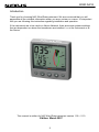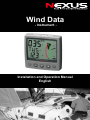
1
Wind Data
- Instrument -
Installation and Operation Manual
English
English
WIND DATA
1
WIND DATA
Introduction
Thank you for choosing NX2 Wind Data instrument. We are convinced that you will
appreciate all the valuable information either you are a cruiser or a racer. It is important
that you are following this instruction regarding installation and operation.
If the instrument are to be used in a Nexus Network, there are some systems settings
that are dependent on where the transducers are installed, i.e. at the instrument or at
the Server.
This manual is written for NX2 Wind Data instrument version 1.00 – 2.10
Edition: March 2007
2
WIND DATA
1
2
3
Part specifications .....................................................................5
Installation ..................................................................................7
Installing the instrument............................................................8
3.1
3.2
3.3
4
Installing cable ............................................................................................. 10
Connections in Nexus Network .................................................................... 10
Connection of log transducer ....................................................................... 11
First start (only in a Nexus Network) ......................................12
4.1
4.2
5
Initialising the instrument ............................................................................. 12
Re-initialising the instrument........................................................................ 12
Operation ..................................................................................13
5.1
5.2
5.2.1
5.2.2
5.2.3
5.2.4
5.2.5
5.2.6
5.2.7
5.3
5.4
5.5
5.5.1
5.5.2
5.5.3
5.5.4
5.5.5
5.5.6
5.5.7
5.5.8
5.5.9
5.6
5.6.1
5.6.2
5.6.3
5.6.4
5.6.5
6
About this manual ........................................................................................ 13
How to use the 5 push-buttons .................................................................... 14
PAGE ...................................................................................................... 14
MINUS ..................................................................................................... 14
PLUS ....................................................................................................... 14
SET ......................................................................................................... 15
Clear ........................................................................................................ 15
Calibration ............................................................................................... 15
Lighting .................................................................................................... 15
Main function ............................................................................................... 16
Analogue function ........................................................................................ 16
Sub-functions............................................................................................... 17
Apparent Wind Speed [AWS] .................................................................. 17
True Wind Speed [TWS].......................................................................... 17
True maximum Wind speed..................................................................... 17
Velocity Made Good (VMG)..................................................................... 17
Battery voltage [BAT], option ................................................................... 18
Boat speed [BSP], option......................................................................... 18
Trip log [TRP], option............................................................................... 18
Water temperature [TMP], option ............................................................ 18
Trim function for optimum Wind angle or speed, option........................... 18
More functions in a Nexus Network ............................................................. 20
Geographic Wind direction (TWD) ........................................................... 21
WCV, Waypoint Closing Velocity ............................................................. 21
X-track error, XTE.................................................................................... 22
HDC / NXT, Course after tack or jibe....................................................... 22
BTW / NXT, Bearing and angle deviation relative next course ................ 23
Calibration.................................................................................25
6.1
C10 User settings ........................................................................................ 25
6.1.1
C11 Select the dampening ...................................................................... 25
6.1.2
C12 Select main information.................................................................... 25
6.1.3
C13 Displaying boat speed, trip log and temperature, option .................. 26
6.1.4
C14 Display NAV functions, option .......................................................... 26
6.1.5
C15 Beep when SET is pressed .............................................................. 26
6.2
C20 Calibration of Log ................................................................................. 26
6.2.1
C21 Select unit for speed ........................................................................ 26
3
WIND DATA
6.2.2
C22 Calibration of log transducer.............................................................26
6.2.3
C23 Unit for temperature..........................................................................27
6.2.4
C24 Temperature offset ...........................................................................27
6.3
C30 Compass Settings.................................................................................27
6.3.1
C31 True or magnetic course...................................................................27
6.3.2
C32 Magnetic deviation............................................................................27
6.3.3
C33 Reference for Compass, static or GPS.............................................27
6.4
C50 Wind Settings .......................................................................................28
6.4.1
C51 Network setting of true or apparent Wind angle................................28
6.4.2
C52 Unit for Wind speed ..........................................................................28
6.4.3
C53 Wind speed calibration .....................................................................28
6.4.4
C54 Adjustment of Wind angle.................................................................28
6.4.5
C55-C62 Calibration table for the Wind transducer..................................28
6.4.6
C63 Speed reference, water or GPS........................................................29
6.4.7
C64 Wind trim reference ..........................................................................29
6.4.8
C68 Roll adjustment.................................................................................29
6.4.9
C69 Pitch adjustment ...............................................................................29
6.5
C70 Configure NX2 ......................................................................................30
6.5.1
C71 Wind-master .....................................................................................30
6.5.2
C72 Log-master .......................................................................................30
6.5.3
C73 Function on terminal In3 ...................................................................30
6.5.4
Connection of trim button .........................................................................31
6.5.5
C74 Demo PAGE.....................................................................................31
7
Maintenance and fault finding ................................................ 32
7.1
Maintenance.................................................................................................32
7.2
Fault finding..................................................................................................32
7.2.1
General ....................................................................................................32
7.2.2
Fault - action ............................................................................................33
7.2.3
Error messages........................................................................................33
8
Specifications .......................................................................... 34
8.1
8.2
9
10
Technical specifications ...............................................................................34
Nexus Network introduction and user policy.................................................34
Optional Accessories .............................................................. 35
Abbreviations........................................................................... 37
11 Warranty ................................................................................................................ 36
4
WIND DATA
1
Part specifications
NX2 Wind Data is delivered with all parts for mounting. Check prior to installation.
Wind Data instrument
Qty.
1
1
1
1
1
2
2
1
1
2
1
5
5
Description
Reference
Instrument, NX2 Wind Data
Instrument front cover
Drill template
Installation and user manual
Warranty card
Pin bolts for instrument mounting
Nuts for instrument mounting
Tube of silicon grease
Connection cover
4-pol screw terminal
Power cable, red and black, 3 m (9 ft)
Extra wire protectors, 0,25 mm (1/100”)
Extra wire protectors, 0,75 mm (1/32”)
1
2
3
4
5
6
6
6
6
6
7
8
8
Additional in Wind Data complete with transducer
1
1
3
1
Mast top cable. 25m (83 ft)
Wind transducer NX2
Mounting screws for mast bracket
Mast head bracket
9
10
11
12
Registering of this product
Once you have checked that you have all the listed parts, please take time to fill in the
warranty document and return it to your national distributor.
By returning this document, it will assist your distributor to give you prompt and expert
attention, in the event of your experiencing difficulties with this product. Keep your proof
of purchase. Also, your details are added to our customer database so that you
automatically receive new product catalogues as and when they are released.
5
WIND DATA
6
WIND DATA
2
Installation
You can install the NX2 Wind Data in three different ways:
•
•
•
•
1.
2.
3.
4.
5.
6.
The wind transducer connected directly to the NX2 Wind Data instrument
By using the connection kit when both log and wind transducers are installed with a
single Wind Data.
The installation may also include a NX2 Server where all transducers may be
connected. All data including power will pass along one cable.
The installation includes 6 major steps:
Read the installation and operation manual.
Plan where to install the transducers and instruments.
Run the cables.
Install the transducers and instruments.
Take a break and admire your installation.
Learn the functions and calibrate your system.
Before you begin drilling ... think about how you can make the installation as neat
and simple as your boat will allow. Plan where to position the transducers, Server
and instruments. Think about leaving space for additional instruments in the future.
•
−
−
−
−
−
A few ”do nots” you should consider:
Do not cut the cables too short. Allow extra cable length at the Server so it
can be disconnected for inspection without having to disconnect all
attached cables.
Do not place sealant behind the display. The instrument gasket eliminates
the need for sealant.
Do not run cables in the bilge, where water can appear.
Do not run cables close to fluorescent light sources, engine or radio
transmitting equipment to avoid electrical disturbances.
Do not rush, take your time. A neat installation is easy to do.
•
The following material is needed:
Wire cutters and strippers.
Small and large Philips and small flat head screw driver.
Hole saw for the instrument clearance hole 63 mm (2½").
5 mm (1/4") drill for the mounting holes.
Plastic cable ties
If you are doubtful about the installation, obtain the services of an experienced
technician.
7
WIND DATA
3
Installing the instrument
•
Place the adhesive drill template on the desired location for the instrument. Drill the
2 holes using a 5 mm (1/4") drill for the two pin bolts. Use a 63 mm (2½") hole saw to
machine the clearance hole for the instrument connection socket. Remove the
template.
•
•
•
Screw the two pinbolts to the instrument
Put the instrument in place
Screw the two nuts from the back
Note! The two nuts must just be tighten by hand
•
•
•
Run the Nexus Network cable from the Server
to the instrument.
If you want to cut the Nexus Network cable to
length, disconnect 4-pole jack plug and cut
the cable. Peel off about 35 mm (1,4") of the
cable insulation. Remove about 6 mm (1/4")
from the 3 isolated wires (the 4th wire is an
earth / screen). Attach the 4 cable protectors
to the wires using a pair of flat pliers.
Connect the 4 cable protectors to the 4-pole
jack plug as shown. Apply silicon paste on all
locations
as
shown.
Note: Must be done to avoid corrosion.
8
Silicon paste
WIND DATA
•
•
Apply silicon paste to the instrument connection pins at the back of the instrument.
Press the jack plug onto the instrument pins. Press the cable in to the cable leads.
Mount the connection back cover with the screw.
Your instrument installation is done!
9
WIND DATA
3.1
Installing cable
The power cable is connected via a 3A fuse from the battery or at the boats fuse panel
and direct to the instrument or Server. One red and one black power wire is included.
Note, set C71 On (see 6.5.1)
Always connect a 3 AMP fuse between Power supply and instrument.
Scree
Black
Green
Yellow
White
Red
3A Fuse
3.2
Connections in Nexus Network
If you already have a Nexus Network i.e. a Server, it is more practical to connect the
transducer to the Server due to the single instrument cable installation. Note, set C71
OFF (see 6.5.1)
Server
Transducer
The instrument is then connected to the Server’s Nexus Network terminal (pin 5, 6, 7
and 8) or any instrument .
From Server or other
NEXUS instrument
10
WIND DATA
3.3
Connection of log transducer
If you have an other log instrument i.e. a NX2 log, a Star log, a D-20 log, a 2200 log or
a 220 log, you may connect the single log pulse wire from that instrument to the Wind
Data instrument terminal 4.
From log transducer,
NEXUS, Star, D-20,
2200 or 220
3A Fuse
If you don’t have a log instrument, but want to install a log transducer, use the
connection box (Art. no: 21453 ).
11
WIND DATA
4
First start (only in a Nexus Network)
4.1
Initialising the instrument
At power on, the instrument will perform a self test. The display will
first show all segments, then the software version number and the
Nexus Network ID number.
At first power on after installation, you will be asked to press SET
[PrSSET]. This will give the instrument a logical ID number on the
Nexus Network.
To initialise the instrument, press SET on all installed digital
instruments, one at the time.
Note: Always wait for the text ”Init OK”
to be displayed, before you press SET
on the next instrument!
The Server automatically gives the first unit ID number 16, then 17
and so on. The order in which you press SET is the same order as
the instruments will be given a logical ID number on the Nexus
Network.
The example shows that the instrument version number is 1.00 and
the given logical ID number is 16.
4.2
Re-initialising the instrument
If two instruments by mistake have the same ID number, this can
cause disturbance and block the information on the Nexus Network.
To re-initialise the instrument, press MINUS and PLUS together
during the power up sequence when version and ID numbers are
displayed.
The display self test is then re-started on all instruments and you
will be asked to press SET on each instrument as explained above.
Note! If you do not succeed to re-initialise, we suggest you
disconnect all but one instrument with the same ID number, then
repeat the above procedure.
12
WIND DATA
5
Operation
5.1
About this manual
•
Each time a push-button are referred to in this manual, the
push-button name will appear in bold and CAPITAL letters, e.g.
PAGE.
•
Unless otherwise
momentary.
•
Each time a function is mentioned in the text, it will be in
brackets and in the same format, where possible, as displayed,
e.g. [AWA].
•
This manual has been written to be: Compatible with Wind Data
instrument from software version 1.0.
•
All functions followed by the text option is not valid in a factory
set-up instrument. See calibration to be able to display these
functions.
stated,
the
push-button
presses
are
Note!
We have put in a lot of effort in order to make this manual correct
and complete. But since we continuously make our products better,
some information can differ from the products functions. If you need
further information contact your national distributor
13
WIND DATA
5.2
How to use the 5 push-buttons
MAIN
FUNCTION
APPARENT
WIND ANGLE
INFOTEXT
TRUE
WIND ANGLE
SUBFUNCTION
TRIM
FUNCTION
CLEAR
MINUS
SET
PLUS
PAGE
5.2.1
PAGE
A press on PAGE change the PAGE of the graphical display. It
scrolls in a circular pattern, one step for every press.
The PAGE button is also used to move the cursor when in edit
PAGE. A press on PAGE moves the cursor in a circular pattern,
one step to the right for every press.
A press on PAGE and MINUS together, back steps cursor to the
preceding step.
When in editing PAGE a long press (>2sec) on PAGE will escape
from that editing PAGE.
5.2.2
MINUS
A press on MINUS moves to the next sub-function.
In edit PAGE it decreases to previous digit.
5.2.3
PLUS
A press on PLUS moves to the previous sub-f unction.
In edit PAGE it increases to next digit.
14
WIND DATA
5.2.4
SET
A press on SET unlocks a digit to access edit PAGE.
When unlocked, the digits are ”active” (flashes) and can be edited
by pressing MINUS, PLUS and PAGE as required.
When finished editing, lock the digit by another press on SET.
5.2.5
Clear
A press on C, clear digits.
5.2.6
Calibration
To access calibration PAGE, press and hold SET more than 2
seconds.
To return to main function PAGE, press SET when the text return
[RET] is shown.
5.2.7
Lighting
The instrument uses red back lighting for the display and the 5
push-buttons. The lighting can be set at 4 different levels.
To quick access the light control, press and hold PAGE for more
than 2 seconds. The flashing text [Lit OFF] will be displayed and
the display will be lit momentarily.
To select between the 4 light levels, press PLUS: [LOW], [MID],
[MAX] and [OFF]. To lock the selected level, press SET.
The selected light level will be copied to all NX2 instruments
connected to the system. When the lighting is on, it is not possible
to reduce or turn off the lighting on an individual instrument.
15
2 sec
2 sec
WIND DATA
5.3
Main function
Top data is relative Wind angle, [AWA] (Apparent Wind Angle). As
an alternative to [AWA] the following can be displayed:
[AWS] (Apparent Wind Speed).
[TWA] (True Wind Angle) if the log transducer is connected.
[TWS] (True Wind Speed) if the log transducer is connected.
To change between these functions, see C12, 6.1.2.
5.4
Analogue function
Change Wind scale between 180° and 60° with PAGE . Selected
scale is shown with the LCD arrow pointing at scale.
The text [APP] displays selected main function as apparent Wind
angle or Wind speed.
MIX 180°
The text MIX 180° means that both APP and TRUE
Wind angle is displayed in scale 180°.
MIX 60°
The text MIX 60° means that both APP and TRUE
is displayed in scale 60.
The scale can be altered between 60° and 180° to get more
accurate readings. At scale 180° each sector represent 5° and at
scale 60° each sector represent 1 2/3°. See the example below .
WIND
16
WIND DATA
5.5
Sub-functions
Select sub-function with PLUS or MINUS.
Information text for the sub-function is displayed. You may also
”park” your favourite function so it will automatically be displayed
after power on.
Press both PAGE and SET to ”park” the displayed function. The
display will flash once to confirm that you have ”parked” the
function.
5.5.1
Apparent Wind Speed [AWS]
The text [AWS] (Apparent Wind Speed) and its value is displayed
below.
The text [AWS] is toggled with the text [KTS] (KnoTS), [M/S]
(Metres/S) or [BF] (Beaufort).
5.5.2
True Wind Speed [TWS]
The text [TWS] (True Wind Speed) and its value is displayed below.
The text [TWS] (True Wind Speed) is toggled with the text [KTS]
(KnoTS), [M/S] (Metres/s) or [BF] (BeauFort).
5.5.3
True maximum Wind speed
Press the SET in the sub-function: [TWS] to display maximum true
Wind speed. After 5 seconds the display will go back to [TWS]
again.
Re-set or clear the [MAX] Wind speed value by pressing CLEAR or
switch off the power.
WIND
WIND
5.5.4
Velocity Made Good
(VMG)
The text [VMG] (Velocity Made Good) is
displayed with the actual boat speed
towards or against the Wind.
The water speed information from the log
transducer is needed. The speed
information can be taken from the log
transducer or from Nexus Network. VMG
= 0.0 knots when the true Wind angle is
perpendicular to the boat.
17
WIND DATA
5.5.5
Battery voltage [BAT], option
The text [BAT] will display battery voltage. The voltage is measured
inside the instrument and will not compensate for any voltage drop
caused by installation.
5.5.6
Boat speed [BSP], option
The text [BSP] will display boat speed (water speed). The text
[BSP] will toggle with selected unit, i.e. (KTS), (KMH) or (MPH).
As an option, you may add or remove displaying boat speed
[BSP], trip log [TRP] and water temperature [TMP]. See further
under calibration.
5.5.7
Trip log [TRP], option
The text [TRP] is displayed and will show trip distance from 0.00 to
99.9 nautical miles, kilometre or miles. After 99.9, 0.00 is displayed.
Clear trip by pressing CLEAR.
5.5.8
Water temperature [TMP], option
The text [TMP] is displayed with water temperature in Celsius or
Fahrenheit.
This function require a NX2/Nexus or Star log transducer.
5.5.9
Trim function for optimum Wind angle or speed, option
The text [TRM] and [OFF] is displayed when this function is off. The
trim function can be used as an aid to keep the correct tacking
angle or to discover speed changes caused by sail or rig trimming.
Some of the functions can only be used when the Wind Data is
connected to Nexus Network.
As the first example we will use [TRM AWA] (TRiM Apparent Wind
Angle).
To trim on wind angle deviation, select the text:
Press CLEAR, the display will flash. Select [AWA] with MINUS and
confirm with SET.
Select the level of dampening [d0-d9] and confirm with the SET.
The default (or latest used) Wind angle is displayed. You may
accept the proposed angle by pressing the SET or enter a new
Wind angle with PLUS, MINUS and PAGE before confirming with
SET.
The entered Wind angle will be lost when power off. You may
18
WIND DATA
however select a default Wind angle in set-up. See C64 6.4.7.
Every time you select this function, or after power up, the pre-set
value is proposed.
On the display you will see the text TRM and AWA toggling
together with your Wind angle. On the graphic part you will see your
reference angle as one straight horizontal segment when actual
angle is equal to the pre-set angle. At the same time you will see
apparent and true Wind angle.
The deviation is displayed visible upwards or downwards from the
horizontal line to +/-15°. The maximum visible deviation is 15°.
When the deviation is between 15° and 30° the 15° sector is lit.
When larger then 30° the segment sector is blanked out.
Trim on speed:
Each sector represents 2°
Select the trim function.
Press CLEAR. Select text (BSP) by pressing PLUS and confirm
with SET.
There is a number of different ”speeds” to be used for trimming.
The most common is [BSP] (Boat SpeeD) and [VMG] (Velocity
Made Good).
The Wind Data instrument can also display deviation from optimum
calculated boat speed [TBS] or (Target Boat Speed).
The TBS is normally calculated by use of polar diagram on PC with
racing software. The value ”Target Boat Speed” is transmitted
through the NX2 Server on the NMEA 0183 input. The Server will
then transmit TBS on the Nexus Network.
On the Wind Data display you will see both the digital value in %
and the graphical value as a 2% variation for each segment.
You may select ”speeds” to TRIM, from this list:
BSP
AWS
TWS
SOG
DRF
Boat speed
Apparent Wind Speed
True Wind Speed
Speed Over Ground
Drift
Log transducer!
WCV
VMG
TBS
Speed towards a waypoint
Velocity Made Good
Optimum speed based on polar diagram
OFF
Function is OFF
19
Log transducer!
Navigator!
Log transducer +
Compass + Navigator!
Navigator!
Log transducer!
PC + NMEA 0183
through
NX2 Server!
WIND DATA
When [BSP] (or other function) is selected, the dampening [d3] is
flashing. Select dampening level and confirm with SET.
The text [% OFF] is then displayed to show that the function is
selected, but no reference is yet set.
Press SET to set [BSP] reference.
The display will now show you the text [%] toggling with text [BSP]
or whatever trim you have selected.
The speed variation is expressed in % from set value.
Press the SET every time you wish to set a new trim reference
value. There is an option to use an external trim button to set a new
trim reference. See more in the calibration.
5.6
MoreEach
functions
inrepresents
a Nexus Netwo
sector
2% rk
By adding (or using) the Wind Data instrument in the Nexus
Network, more functions will be added if the corresponding
transducer is connected.
The Wind Data functions may be added or removed by the user.
The Wind Data instrument can be used in a small Network together
with the Multi, Log or analogue instrument, without a Server.
In order to make the installation easy when using both log and Wind
transducer in a small Network we recommend you to install with
connection kit art.no. 21453. Only one cable will carry the signals to
the instrument, then there is one Network/power cable to the Multi
or Log instrument. (See 3.3).
When using the Wind Data in a bigger Network with more then 3
transducers, we recommend you to use the NX2 Server.
Only one cable will be used to connect all instruments. You will also
have the NMEA 0183 input/output.
If you need to be able to read the depth information on more then
one instrument, the Server is the only choice.
Network bonus function:
20
WIND DATA
If you are using the race timer on the Multi or Log instrument you
will have a graphical 60 second countdown timer ”popping up” on
this instrument.
In this example there is 45 second to start.
5.6.1
Geographic Wind direction (TWD)
To get this function, set NAV = On C14 (See 6.1.4).
Text [TWD] is displayed shortly, then is the abbreviation for Wind
directions displayed, [SSW], [NO], [WNW] etc. together with the
numerical direction below. The graphic direction is also displayed
by pressing PAGE one or more times until the display to the right is
displayed together with the ”pointer”.If the Compass transducer is
missing but there is a GPS installed, you may use the GPS as a
reference for heading under the criteria that the vessel must be
moving. Change C33 from USE Hdc to USE COG.
(See 6.3.3)
When the boat is laying still, the TWD will be random readings
if COG is used.
You may also check long term geographical Wind shifts by
entering a ”marker” at present Wind direction as a remainder.
The ”marker” will stay until power off or by clearing the function.
A Wind shift of 5° will be easy to detect after hours of sailing.
Select function [TWD 360°] with PAGE, and when the text [TWD] is
flashing press SET.
The ”marker” is now set. When there is a constant Wind shift, you
will see this ”marker” as a slow blinking reminder of the origin Wind
direction.
5.6.2
WCV, Waypoint Closing Velocity
To get this function, set NAV = On C14 (See 6.1.4).
5° towards your
The text [WCV] is dispEach
layedsector
with therepresents
actual speed
Waypoint if a Waypoint is selected in your GPS navigator.
21
WIND DATA
5.6.3
X-track error, XTE
To get this function, set NAV = On C14 (See 6.1.4).
The text [XTE] is displayed shortly when this function is selected,
then a symbolic ”boat” is displayed on one side of the ”road” which
is displayed as three vertical lines.
Your ”boat” will be displayed on the right or left side of the road.
The distance is also displayed and can be in either Nautical mile,
Km or Miles.
5.6.4
HDC / NXT, Course after tack or jibe
To get this function, set NAV = On C14 (See 6.1.4).
This function also needs a Compass connected to the NX2 Server
If the Compass sensor is missing, the HDC may be replaced by the
COG (Course over ground) by setting the reference in COG. (See
C33 6.3.3).
The text [HDC] is displayed with actual magnetic or true heading.
After 4secs. the text [NXT] together with the true or magnetic
course to keep after tack or jibe.
Note! The boat’s drift must be included in your decision when to
tack, to reach the mark.
After a tack, it will take some minute before the new tack angle is
steady due to the dampening.
The functions [HDC] and [NXT] is toggling, but they can be locked
or unlocked by use of the SET.
22
WIND DATA
5.6.5
BTW / NXT, Bearing and angle deviation relative
next course
To get this function, set NAV = On C14 (See 6.1.4).
This function is using both the Compass and the navigator
information to calculate the angle deviation between the bearing
and the course after tack. i.e. the angle deviation is exactly what
you should expect after the tack.
[BTW] is showing the actual Bering to Waypoint and [NXT] is
showing the negative [-], positive tack or downwind angle that you
would expect if you where tacking or jibing.
You may use COG but our recommendation is to use the Compass
since the response and accuracy is superior. If you use COG
without a differential GPS you will loose too much accuracy in the
information.
[BTW] and [NXT] is toggling.
TACK :
Example: If you expect your drift to be 05°, your tack should be
made when you read [NXT 05°] to be on (and stay on) lay line.
While you are approaching the proper angle, the value is negative,
i.e. -12° and then increasing to 00° which is on lay line after tack
except for the drift which is the margin you must add to compensate
for the drift.
Note! This function is only used on the last leg.
WIND
23
WIND DATA
Down Wind:
When sailing down Wind, the boat can always be sailing at the
highest WCV (speed towards the mark). When [NXT] is [00°] you
should jibe because your drift is not important.
The functions [BTW] and [NXT] is toggling, but can be locked or
unlocked by use of the SET.
Note! This function is only used on the last leg.
WIND
24
WIND DATA
6
Calibration
To get the most out of your NX2 instrument, it is important to
carefully calibrate the instrument. The calibration values are stored
in a non volatile memory.
To access calibration PAGE, press and hold SET more than 2 seconds.
To select a calibration code, press MINUS, PLUS and PAGE as required.
To return to normal operation PAGE, press SET when the text
return (RET) is displayed.
The different calibration routines are divided into five groups:
C10 - C15 = USR, User settings.
C20 - C24 = BSP, Log transducer and temp calibrations.
C30 - C33 = HDC, Compass settings.
C50 - C64 = WND, Wind transducer settings/calibrations.
C70 - C74 = CON, Configuration of the NX2 system.
To change a calibration value, press SET.
To select calibration value, press MINUS, PLUS and PAGE as
required.
To lock the selected value, press SET.
6.1
C10 User settings
To return to normal PAGE, press SET when the text [rET] is
displayed.
6.1.1
C11 Select the dampening
The dampening will affect Wind angle, Wind speed, boat speed and
VMG. Dampening is between d0 (0s) and d9 (1’20).
To change the dampening, press SET and change with PLUS or
MINUS and enter with SET.
6.1.2
C12 Select main information
Select function to be display at the top left of the LCD display.
There is five options.
AWA
Apparent Wind Angle.
TWA
True Wind angle by the use of log transducer.
AWS
Apparent Wind speed.
TWS
True Wind speed by use of log transducer.
WIA
Main setting for the NX2 system. When selected,
all instruments using WIA will be system affected and
following
the set-up in the Multi Control setting C51.
25
WIND DATA
6.1.3
C13 Displaying boat speed, trip log and
temperature, option
When set to OFF, the functions will be removed from the display.
The Wind Data instrument may be used as a Server in the Nexus
Network, transmitting the log and temp to other NX2 instruments
without having the information displayed in this instrument.
6.1.4
C14 Display NAV functions, option
NAV functions are only useful when the Wind Data is connected in
a Nexus Network with Compass transducer and a navigator. The
selection NAV On will add the functions BTW, XTE etc.
6.1.5
C15 Beep when SET is pressed
Setting On will make a beep at every key press, while OFF is silent.
6.2
C20 Calibration of Log
To return to normal PAGE, press SET when the text [rET] is
displayed.
6.2.1
C21 Select unit for speed
Unit for speed, knots (KTS), km/h (K/h) or miles/h (m/h).
6.2.2
C22 Calibration of log transducer
Calibration value for speed and distance (1.00 - 1.99).
Drive the boat a measured distance at normal speed.
Compare the distance with the trip counter.
Calculate the value with the following formula.
True distance from the sea chart:
Log trip counter distance:
The current calibration value:
New calibration value:
T
L
C
N
If you suspect a current in the water, drive the boat in both
directions and divide trip counter distance by two.
If the Wind Data is installed with NX2 Server where the log is
already calibrated, no further calibration is needed.
26
WIND DATA
6.2.3
C23 Unit for temperature
Select degree Celsius [C] or degree Fahrenheit [F].
6.2.4
C24 Temperature offset
By adding a positive or [-] negative value here, it will be added as
an offset before displayed as the temperature.
6.3
C30 Compass Settings
To return to normal PAGE, press SET when the text [rET] is
displayed.
6.3.1
C31 True or magnetic course
This function is only used when the instrument is connected in the
Nexus Network. [MAG On] will display bearing, course and Wind
direction as magnetic. The LCD indication is (MAG). Select [OFF]
to display all as true.
6.3.2
C32 Magnetic deviation
Set the deviation direction first, i.e. [+E] (East) or [W] (West), then
enter the magnetic value in 1/10 of a degree.
6.3.3
C33 Reference for Compass, static or GPS
Select heading Compass [Hdc] when the Compass transducer is
connected to the Nexus Network (recommended).
Select course over ground [COG] when a GPS navigator is
connected, but no Compass.
Select STA for static use at fixed installations, such as at the yacht
club, airfield, ferry berth and so on.
In static PAGE you may mount the transducer in the direction of
North, or if not possible, you may adjust the transducer
electronically. See C54, 6.4.4.
Note! [COG] as reference will only operate properly when the boat
is doing speed over ground.
27
WIND DATA
6.4
C50 Wind Settings
To return to normal PAGE, press SET when the text [rET] is
displayed.
6.4.1
C51 Network setting of true or apparent Wind
angle
Select true [TWA] or apparent Wind angle [AWA] as main function.
The optional analogue Wind instrument will display the same
selection. All Multi Control instruments which have the calibration
code 63 set to [WIA] will display what is selected in C51.
6.4.2
C52 Unit for Wind speed
Unit for Wind speed [KTS] for (KnoTS), [M/S] for (Metres/S) and
[BF] for (Beaufort).
6.4.3
C53 Wind speed calibration
Use 1.50 for a single fin transducer (with two propeller blades)
Use 1.70 for a twin fin transducer (with three propeller blades)
6.4.4
C54 Adjustment of Wind angle
Mast top unit misalignment adjust value or the so called ”A-fault”,
makes it possible to adjust any horizontal angle.
Example: If the Wind angle is +4° when you sail/drive the boat
straight into the Wind, set the calibration value in C54 to 356°.
6.4.5
C55-C62 Calibration table for the Wind
transducer
In channels C55 to C62 you set the calibration values for the mast
top unit. Each mast top unit is individually calibrated for best
accuracy. See the separate Wind calibration certificate supplied
with each mast top unit. Each of the inter-cardinal directions are
calibrated.
C55
C56
C57
C58
C59
C60
C61
C62
000
045
090
135
180
225
270
315
000°
045°
090°
135°
180°
225°
270°
315°
Set the calibration value according
to the provided calibration certificate
28
WIND DATA
6.4.6
C63 Speed reference, water or GPS
This function is only used when the instrument is connected in the
Nexus Network. When [BSP] is selected, the reference is water
speed provided by the log transducer for calculation of true Wind
speed and angle, VMG and NXT function together with the BTW.
When [SOG] is selected, the reference is speed over ground.
Note! the boat must be moving to give correct readings. We also
recommend you to use differential GPS to get good readings.
6.4.7
C64 Wind trim reference
This default reference for Wind angle trim. Each time the instrument
is powered up and apparent Wind angle is selected as trim
reference this value will be pre-set.
6.4.8
C68 Roll adjustment
This adjustment is valid only if roll is selected in C73 (you have to
exit and enter the calibration again after C73 is set to Roll.)
Adjustment of the roll offset. Mount the roll transducer according to
the instructions. Adjust the offset so the roll is displaying 00° when
the boat is horizontal. By entering a minus sign [-] in front of the
value the roll will be decreased by the value. When the offset is
without a minus sign, it will be added. When a roll transducer is
connected the Wind- speed and angle will be compensated for roll
and accuracy is increased.
The roll sensor is not yet available (at the time for this manual).
6.4.9
C69 Pitch adjustment
This adjustment is valid only if roll is selected in C73 (you have to
exit and enter the calibration again after C73 is set to Roll).
Adjustment of the pitch offset. Mount the pitch transducer according
to the instructions. Adjust the offset so the pitch is displaying 00°
when the boat is horizontal. By entering a minus sign [-] in front of
the value the roll will be decreased by the value. When the offset is
without a minus sign, it will be added. When a pitch transducer is
connected the Wind speed and angle will be compensated for pitch
and accuracy is increased. Pitch does not affect Wind speed and
angle as much as roll.
29
WIND DATA
6.5
C70 Configure NX2
To return to normal PAGE, press SET when the text [rET] is
displayed.
In the configuration you will be able to tell the Nexus Network where
you have installed the log and Wind transducer.
This is important because you may optionally install those
transducers at the Server too.
6.5.1
C71 Wind-master
[On] = the Wind transducer is connected at the Wind Data
instrument.
[OFF] = the Wind transducer is connected at the NX2 Server.
6.5.2
C72 Log-master
[On] = the log transducer is connected at the Wind Data
instrument.
[OFF] = the log transducer is connected at the NX2 Server.
6.5.3
C73 Function on terminal In3
Select function on the terminal pin 3. The following functions are
available:
[TMP]
[TRM]
[SPT]
[MOB]
[Roll]
Standard temperature function from the log transducer.
Use the external trim button for the STEER Pilot function.
Use the external trim button for the SPEED TRIM function.
Use the external trim button for the M.O.B. function.
Use the roll sensor to compensate Wind speed and angle.
(Not yet available, at the time for this manual).
When the selection roll is made, further settings in calibration can
be made to correct the offset angle. See C68 6.4.8. You may still
use the water temperature by connecting the log transducer at the
Server.
When Speed Trim [SPT] is selected, a press on the external trim
button will transmit the trim command on the Network to all
instrument. To be able to set both the STEER reference and the
TRIM reference, the optimum way is to connect one trim button for
speed to the Wind instrument and connect one trim button for
Compass and Wind angle to the Server. Such a installation gives
you the opportunity to trim speed and angle at two separate
buttons.
30
WIND DATA
6.5.4
Connection of trim button
Connect the trim button as per the
drawing. The button should make
connection when pressed. It is also
possible to connect more than one
button in parallel, for example one on
starboard and one on port.
Article number
for the push button: 19763.
6.5.5
C74 Demo PAGE
The Wind Data instrument has a built in demonstration PAGE. All
values are simulated in this PAGE. It is convenient to learn the
functions of the instrument by using this PAGE.
Every 7th second the text DEM will appear to alert you that demo
PAGE is selected.
31
WIND DATA
7
Maintenance and fault finding
7.1
•
•
•
•
•
Maintenance
To clean the instrument, use only mild soap solution and rinse with water.
Do not use detergents or high pressure washing equipment.
At least once a year, check all your connections and apply additional silicon paste at
each connection point.
Always use the instrument cover for protection, when not in use.
Storing transducers and instruments when not in use for longer periods: It is
advisable to remove the instruments and transducers, and store them inside the
boat or at home in room temperature, if possible.
7.2
Fault finding
Before you contact your NX2 dealer, and to assist your dealer to give you a better
service, please check the following points and make a list of:
• All connected instrument and transducers, including their software version numbers.
• Instrument software version number.
• Nexus Network data bus ID numbers for each instrument (displayed at power up).
7.2.1
General
In most cases, the reason for faults in electronic equipment is the installation or poor
connections. Therefore, always first check that:
•
•
•
•
•
•
•
•
•
•
Installation and connection is made per instructions for instrument and transducers,
(see 3.3).
Screw terminals are carefully tightened.
No corrosion on any connection points.
No loose ends in the wires causing short cuts to adjacent wires.
Cables for damage, that no cables are squeezed or worn.
Battery voltage is sufficient, should be at least 10 V DC.
The fuse is not blown and the circuit-breaker has not opened.
The fuse is of the right type.
Two instruments do not have the same ID number, (see 4.2).
Check the following important settings: C13, C14, C33, C63, C71 and C72.
32
WIND DATA
7.2.2
Fault - action
1. Wind: No reading [ --- ]
• If inaccurate Wind data is received, check the connections (separate through deck
connection or below decks connection), are properly made.
• Make sure the transducer is aligned correctly, (see C54, 6.4.4).
• Measure with a voltmeter, at the screw terminal pin 1 and ground, and between pin
2 and ground.
• If the voltmeter shows 1.5 to 4 V DC (minimum Wind speed 3 m/s) at both
measuring points, the transducer and the connections are OK.
• If the voltmeter shows 0 or 5 V DC at both measuring points, the transducer or the
connections are defect. Contact you NX2 dealer with this information.
2. Speed and distance functions: No reading [ --- ]
• C13 should be ON. See 6.1.3.
• If you have a voltmeter available, you can check the condition of the transducer.
When measuring with voltmeter make sure everything is connected, that the power
is on and make sure the paddle wheel is rotating.
• At the back of the instrument, measure between pin 4 and ground.
• When not rotating, the value should be fixed at either about 0 or 5 V DC. When
rotating very slowly, by hand, the value should flip between 0 and 5 V DC. When
rotating faster, the value should average around 2.5 V DC.
Irregular values: Check the speed damping (SEA), (see C11, 6.1.1).
•
3. Compass functions: No reading [ --- ]
C14 should be ON. See 6.1.4
7.2.3
Error messages
The following error messages can appear on the display:
ERROR 2
ERROR 3
ERROR 10
ERROR 11
Nexus Network is missing, check colour coded connections
No Network data received within a given time.
Range error caused by bad format, e.g. 430°.
Remote command that can not be performed.
If other error messages than the above appears on the Wind Data instrument, contact
your NX2 dealer.
33
WIND DATA
8
Specifications
8.1
Technical specifications
Dimensions:
Wind Data instrument: 113 x 113 mm.
(4.3x4.3 inch)
Instrument cable:
Power supply:
Power consumption
Instrument:
Log- and temp sensor:
Wind transducer:
Temperature range:
Weight:
Enclosure:
12 V DC (10-16 V). The instrument is polarity
protected.
0,08 W
0.8 W (at max illumination)
12 mW
50 mW
Storage: From -30°C to +80°C.( -22°F to 176°F)
Operation: From -10°C to +70°C. (14°F to 158°F)
Instrument: 283 g (9.98 oz).
Transducer: 293 g (10.33 oz).
Instrument. Water proof
CE approval
The products conforms to the EMC requirements for immunity and emission according to
EN 50 08-1,
8.2
Nexus Network introduction and user policy
Introduction:
The Nexus Network is a Multi talker Multi receiver data bus specially designed for
marine navigation applications. It utilises the RS485 standard with up to 32 senders
and/or receivers to form a Local Area Network. Data is transmitted synchronously with 1
start-bit, 8-data-bits, 1 parity-bit, two stop-bits in 9600 baud.
User policy:
The Nexus Network is open for new users and applications without the licence or a
licence fee. The data bus however is, the property of the manufacturer, which means
the specification must be followed in order to protect the manufacturer’s commitments
to the Nexus Network performance and safety.
For most PC-applications, the full duplex interface (Art. No. 21248), will be a very useful
tool for monitoring real time data, to edit and store Waypoints to PC-file or to Server
and/or to the NX2 GPS. The interface is supplied with a cable for connection from PC to
the Server or NX2 instruments and/or the NX2 GPS. A 9-pole D-sub connector is
connected to the RS232 port on the PC.
34
WIND DATA
9
Optional Accessories
Below find a selection of optional accessories available. Please contact your local NX2
dealer for more information.
22118-3
22118-2
22118-1
22118-4
22118-5
22118-6
NX2 Completes
Multi Control instrument and Server, 8m cable
Multi Control and Server with Speed Log and depth transducer, 8m cable
Speed log with log transducer, 8m cable
Wind Data, with transducer, 25m cable, mast bracket
Compass Data, with transducer 35°, 8 m cable
GPS Navigator, with GPS Antenna, 8+10m cable
22120-1
20707
19915-8
21731
20860
20721
20721-1
20594
21721
69980
21970
21735
NX2/Nexus Transducers
Server compl with 3m power cables
Log/Temp transducer, 8 m cable (for Nexus and Star)
Depth transducer, 8m cable (for NX2 only)
Compass transducer 35°, 8m cable
Compass transducer 45°, 8m cable
Wind transducer, 25m cable, mast bracket
CF-wind transducer, Carbon Fibre, 1260mm long, 380g, no mast cable incl.
Nexus mast cable 25m
MTC (Mast Twist Compensation) box, 8m cable, for Wind Data instr.
MRC (Mast Rotation Sensor Compensation) box
GPS Antenna, with NMEA 0183 output
Bracket for GPS Antenna and 35° Compass transducer for bulkhead mount
22117-1
22117-3
22117-4
22117-5
22117-6
22117-7
NX2 Digital Instruments (all supplied with 0.2m cable)
Speed log instrument
Multi Control instrument
Wind Data instrument
Compass Data instrument
GPS Navigator instrument
Autopilot instrument
22115-01
22115-02
22115-03
22115-05
22115-06
22115-07
22115-08
22115-09
22115-10
22115-11
22115-12
22115-13
NX2 Analog Instruments (all supplied with 0.2m cable)
NX2 Analog Wind Angle
NX2 Analog Steer Pilot
NX2 Analog Speed Trim
NX2 Analog Speed 0-16kts
NX2 Analog Speed 0-50kts
NX2 Analog Depth 0-200m
NX2 Analog Depth 0-600ft
NX2 Analog Rudder angle
NX2 Analog Compass
NX2 Analog GPS Speed 0-16kts
NX2 Analog GPS Speed 0-50kts
NX2 Analog GPS Course
21210
21218-1
20966
Nexus Remote Control Instrument
Remote Control Instrument (RCI), with Autopilot control, 5m cable, bracket
Bracket Remote Control instrument
Connector 4-pole, NEW model (Allows cable - cable connection)
35
WIND DATA
21680-1
21684-1
69995
Nexus Multi XL
Multi XL instrument, 4m cable (RCI or Multi Center needed to control Multi XL)
Multi XL Set, Multi XL instrument and Remote Control instrument
Mast bracket XL, in aluminium for Multi XL and Nexus / Star 110x110mm instr.
22118-6
22117-6
21970
20992-2
21735
NX2 GPS
GPS Navigator, with GPS Antenna, 8+10m cable
GPS Navigator instrument
GPS Antenna, with NMEA 0183 output
Bracket GPS Antenna, plastic with female thread 1" x 14 tpi
Bracket for GPS Antenna and 35° Compass transducer for bulkhead mount
22117-7
21210
22115-09
Nexus Autopilot components
Autopilot instrument
Remote Control instrument, with Autopilot control, 5m cable, bracket
NX2 Analog Rudder angle
21035-2
20860
21731
21036
69981
Servo Unit A-1510, 8m cable
Compass transducer 45°, 8m cable
Compass transducer 35°, 8m cable
Rudder Angle Transmitter RFU-25, 15m cable, ball joint linkage 230mm x 2
Linear Rudder Angle Transmitter
21134
21134-24
21341
21341-24
21136
69991-12
Pumpset PF-0.3 12V
Pumpset PF-0.3 24V
Pumpset PF-0.3S 12V, with solenoid
Pumpset PF-0.3S 24V, with solenoid
Linear Drive AN-23, stroke 229mm, peak thrust 680kg
Integrated Linear Drive HP-40, stroke 254mm, peak thrust 500kg
36
WIND DATA
10 Abbreviations
BSP
BTW
C
F
KM
KTS
MH
LCD
LOW
MID
MAX
RET
SOG
TRP
_
Boat Speed
Bearing To Waypoint
Celsius
Fahrenheit
KiloMetre
KnoTS
Miles per Hour
Liquid Crystal Display
LOW
MID
MAX
RETurn
Speed Over Ground
TRiP
Minus
Plus
37
WIND DATA
WARRANTY
GENERAL
All our products are designed and built to comply to the highest class industry standards. If the
products are correctly installed, maintained and operated, as described in the installation and
operation manual, they will provide long and reliable service. Our international Network of
distributors can provide you with the information and assistance you may require virtually anywhere
in the world.
Please read through and fill in this warranty card and send it to your national distributor for
product registration.
LIMITED WARRANTY
The warranty covers repair of defective parts due to faulty Manufacturing and includes labour when
repaired in the country of purchase. The warranty period is stated in the product manual, and
commences from the date of purchase. The above warranty is the Manufacturer’s only warranty
and no other terms, expressed or implied, will apply. The Manufacturer specifically excludes the
implied warranty of merchantability and fitness for a particular purpose.
CONDITIONS
•
The supplied warranty card and receipt with proof of purchase date, must be shown to validate
any warranty claim. Claims are to be made in accordance with the claims procedure outlined
below.
•
The warranty is non-transferrable and extends only to the original purchaser.
•
The warranty does not apply to Products from which serial numbers have been removed,
faulty installation or incorrect fusing, to conditions resulting from improper use, external
causes, including service or modifications not performed by the Manufacturer or by its national
distributors, or operation outside the environmental parameters specified for the Product.
•
The Manufacturer will not compensate for consequential damage caused directly or indirectly
by the malfunction of its equipment. The Manufacturer is not liable for any personal damage
caused as a consequence of using its equipment.
•
The Manufacturer, its national distributors or dealers are not liable for charges arising from
sea trials, installation surveys or visits to the boat to attend to the equipment, whether under
warranty or not. The right is reserved to charge for such services at an appropriate rate.
•
The Manufacturer reserves the right to replace any products returned for repair, within the
warranty period, with the nearest equivalent, if repair within a reasonable time period should
not be possible.
•
The terms and conditions of the warranty as described do not affect your statutory rights.
CLAIMS PROCEDURE
Equipment should be returned to the national distributor, or one of its appointed dealers, in the
country where it was originally purchased. Valid claims will then be serviced and returned to the
sender free of charge.
Alternatively, if the equipment is being used away from the country of purchase, it may be returned
to the national distributor, or one of its appointed dealers, in the country where it is being used. In
this case valid claims will cover parts only. Labour and return postage will be invoiced to the sender
at an appropriate rate.
DISCLAIMER
Common sense must be used at all times when navigating and the Manufacturer’s navigation
equipment should only be considered as aids to navigation.
The Manufacturers policy of continuous improvement may result in changes to product
specification without prior notice.
38
WIND DATA
File id:
WARRANTY CARD
TO BE RETURNED TO YOUR NATIONAL DISTRIBUTOR
OWNER:
Name:
Street :
City/Zip Code :
Country:
Product name:
Serial number:
A
B
C
1
2
3
4
5
6
7
Date of purchase: _______________ Date installed ________________
Dealers stamp:
Tick here if you do not wish to receive news about future products
39
WIND DATA
40
Copyright ©:
Nexus Marine AB
Kuskvägen 4, 191 62 Sollentuna, Sweden
Tel: +46 -(0) 8 – 506 939 00. Fax: +46 -(0) 8 -506 939 01
www.nexusmarine.se
41
22134-1 Edition 3
WIND DATA