1
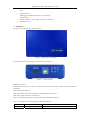
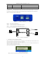
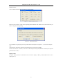
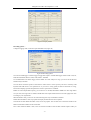
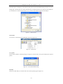
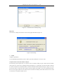
Guangzhou ZLG-MCU Development Co., LTD
USB Analyser user manual
1.
Introduction
USB Analyser is a high cost performance USB bus development tool manufactured by Guangzhou ZLG-MCU
Development Co., LTD.. The USB Analyser is based on specific USB chip and advanced MCU. It integrates the
DPLL, FIFO, automatic synchronization, USB bus disturbance detection and USB1.1/USB 2.0 compatible
technologies. We also provide USB development boards and publications about USB. See our web site
http://www.zlgmcu.com for more information about us.
2.
System Requirements
(1) Monitor PC
•
Pentium IV 1.0G or above, or compatible CPU
•
USB 2.0 port
•
256MB RAM or above
•
Minimum 500MB hard disk space
•
CD-ROM or DVD-ROM driver
•
Windows 98, Windows 2000, Windows XP or above. Windows XP is recommended.
(2) Debug Host
•
A Device conforms to the Universal Host Controller (UHC) or Open Host Controller (OHC)
specification (E.g. PC, industry PC, notebook PC, PDA, etc.).
Note:Not support use low speed device in Hub
3.
4.
Features
•
Small, light and easy to take;
•
Two power supply mode, can meet the requirements of different computers;
•
USB 2.0 port, can run on Windows 98, Windows 2000, Windows XP;
•
Capture and analyze full speed and low speed data of USB1.1;
•
PID or multiple manual trigger modes are available;
•
Data auto-trace on USB bus, ensuring the integrity and inerrability of data;
•
Analyze USB bus error and data transmission error;
•
Optional capture capacity, can be defined from 1 to 99MB;
•
Powerful search capability, can find any error frame or specified data;
•
USB protocol Decoding makes data easy to know;
•
Spare time statistics, data transmission is clear at a glance;
•
Perfect data statistics, conveniently allocating USB bandwidth.
Technical parameters
•
USB monitor port: Supports USB 2.0 port and USB 1.1 port;
•
USB capture port: Supports USB 1.1 port;
•
USB capture port input impedance: >10MΩ
•
Data capture capacity: 1~99MB
•
Capture speed: USB 1.1 Full-speed and Low-speed
•
Capture content include Sync,PID,ADDR,ENDP,CRC5,CRC16,Frame Number,DATA,struff error,idle
-1-
Guangzhou ZLG-MCU Development Co., LTD
time
•
Triggering mode:
PID trigger: All PIDs defined in USB 1.1 specification;
Manual trigger;
5.
•
IDLE time statistics:
•
External power: 6V
Min: 3; Max: 14336 bit; (±1 tolerance)
Hardware
The top view of USB Analyser is shown in figure 1.
Figure 1
USB Analyser’s appearance
The control terminals of USB Analyser are shown below (see figure 2).
Figure 2
Control terminals
POWER: Power input
MONITOR: USB 2.0 port. It’s used to connect with monitor PC and transmit control command and monitor
information.
RUN: Running state indicator
USB: USB connection (between USB Analyser and monitor PC) state indicator
POW: Power supply indicator of USB Analyser.
Table 1 is the mapping of indicator color to the state of RUN and USB respectively.
Table 1
Off
The meanings of indicating LEDs for RUN and USB states
RUN
USB
Standby state
Disconnected with USB bus or can not detect USB bus
-2-
Guangzhou ZLG-MCU Development Co., LTD
Green
Capture state
Connected with USB
Red
Transmission state
USB 2.0 port is available
Green and Red
Capture and Transmission
Running on USB 2.0 protocol
During power on, RUN and USB indicators will blink once then off. Then only RUN indicator is on and color is
red. After device has connected to USB correctly, RUN indicator turns off. USB indicator will be constantly on.
Figure 3 is the capture terminal of USB Analyser.
Figure 3
Capture port
RESET
Reset button of USB Analyser.
USB-B
Capture input/output port of USB Analyser (type B)
USB-A
Capture output/input port of USB Analyser (type A).
The connection of USB Analyser shows in the following figure.(Figure 4)
USB Cable
POWER
USB Debug Device
USB-A
USB Cable
Monitor PC
(Run USBAnalyser software)
MONITOR
USB Analyser
USB-B
USB Cable
RUN
USB
POW
RESET
Figure 4
6.
Debug Host
(PC、IPC、
NoteBook、PDA etc.)
Connection of USB Analyser
USB Analyser software installation and using
Double click setup.exe in the Software directory of attaching CD, install USB Analyser software and driver. You
can connect and use the USB Analyser after software installation.
Note: Please install the USB Analyser software first, and then connect and use the Analyser, because the driver of
Analyser is packed in the installation program.
When connected with the Monitor PC, the computer will show a prompt like Figure 5.
Figure 5 Found New Hardware
Double click the icon, open the Found New Hardware Wizard.(Figure 6)
-3-
Guangzhou ZLG-MCU Development Co., LTD
Figure 6
Open Found New Hardware Wizard
Select Install the software automatically, then press Next button. The computer will search the driver
auomatically.(Figure 7)
Figure 7
Search the driver
If you using Windows XP or Windows 2000, it will popup a dialog like Figure 8.
-4-
Guangzhou ZLG-MCU Development Co., LTD
Figure 8 Windows logo testing
Press Continue Anyway, the computer start to copy the driver. When finish installation, it will show a dialog link
Figure 9.
Figure 9 Completing the Found New Hardware Wizard
Click Finish. The right bottom corner of status bar will show a finish installation prompt.(Figure 10)
Figure 10 finish installation prompt
You can look into the Device manager to see whether install the driver succefully.(the red rectangle in Figure11)
-5-
Guangzhou ZLG-MCU Development Co., LTD
Figure 11 Device Manager
When finish installation , open the USB Analyser software , it looks like Figure 12.
Figure 12
The menu of USB Analyser
The following sections describe the menus on the USB Analyser menu bar:
File menu
The File menu includes commands you use to work with USB Analyser file. There are 8 available options (Figure
13).
Figure 13
File menu
-6-
Guangzhou ZLG-MCU Development Co., LTD
New: Clear current displayed record and build a new blank record file.
Open: Open a previous USB Analyser record file.
Save and Save As…: Save current recorded data with specified name.
Print: Print the current displayed data.
Print Preview: Preview the print effect on PC.
Printer Setup: Configure the printer.
Exit: Quit USB Analyser software.
View menu
You can choose whether to display the tool bar or status bar on View menu (Figure 14).
Figure 14
View menu
Setup menu
You can use Setup menu to configure the working mode of USB Analyser.(Figure 15)
Figure 15
Setup menu
Field color
Configures the colors of data record, you can customize the color (Figure 16).
Figure 16
Color setting panel
-7-
Guangzhou ZLG-MCU Development Co., LTD
Hidden Elements…
Choose which kinds of data that do not display in main window.
Figure 17
Hidden Elements panel
When you select a Field or a PID, the corresponding field and PID will hide. When select IN,OUT or SETUP, you
need to config the following dialog:
Figure 18
Hide packet dialog
You can hidden or display data packet of specified address and endpoint. If endpoint is –1, it means all endpoints.
Note:
1.When NAK is selected, all NAKs and respond data packets of NAK will be hidden.
2.when select IN,OUT or SETUP, it will hide all the subsequent data packets(DATA0 or DATA1) and respond
packets(NAKs or ACKs).
Display formats
Set up the display format of recorded data. You can choose to display in Binary or HEX, MSB locate in left or
right (Figure 19).
-8-
Guangzhou ZLG-MCU Development Co., LTD
Figure 19 Display formats
Recording options…
Configure Trigging mode, connection speed and buffer size (Figure 20).
Figure 20 Recording options
You can select PID trigger or manual trigger to toggle data capture. Available PID trigger modes include: OUT, IN,
SOF, SETUP, DATA0, DATA1, ACK, NAK, STALL, and PRE.
It’s recommended to use manual trigger, because buffer size of the Analyser is large, you can record all data first
and then analyze the data.
You can choose connection speed in Connection box. Please select a correct speed of your device. Generally, USB
keyboard and USB mouse is low-speed devices. If you select a wrong speed, the data recorded will be wrong,
because the sampling speed of full-speed device and low-speed device is different.
Buffer size is the sample buffer capacity, you can choose 1 to 99 MB, and default is 4MB. Note: The larger buffer
size you select, the longer time is needed to handle data after capture finished. Please select the appropriate value
according to your requirements.
When the buffer is full, you can use one of the following three ways to handle this situation:
STOP: When the buffer is full, stop capture and display the data that have been captured.
Override the old data: When the buffer is full, do not stop capture. The new data will override the old data in the
buffer. And the data in buffer are the newest data.
Save to disk: When the buffer is full, it will save the data in buffer to files and then continue capture. When you
-9-
Guangzhou ZLG-MCU Development Co., LTD
select this option, it will display a select directory dialog. Please ensure the harddisk which your files save in have
enough space. The data will save as files in the directory you selected, and the size of each file is the buffer size
you selected above. The file extension name is .usb. you can use this software open the file and analyze.
Figure 21
Select directory
Search menu
You can use it to search the packet and PID that you specify (Figure 22).
Figure 22
Search menu
Go to packet
Enter the packet number in following dialog box (Figure 23) and click OK. It will goto and display the specified
packets.
Figure 23
Enter Packet number dialog
Find PID
Find specific PID. When you select this menu item, following dialog appears (Figure 24).
- 10 -
Guangzhou ZLG-MCU Development Co., LTD
Figure 24
Find PID dialog
The avalible PID including:
Token: IN, OUT, SOF, SETUP;
Data: DATA0, DATA1, Both (both DATA0 and DATA1);
Special: PRE;
Handshake: ACK, NAK, STALL;
Other: Invalid;
Note: Invalid means to find invalid data.
Find Errors:
This menu item is to find error data. When you select this menu item, following dialog appears (Figure 25).
Figure 25
Find errors dialog
Following are selectable error conditions:
Bad PID: Indicates PIDs that do not exist in USB 1.1 specification.
Bit Stuffing: There are disturbances on USB bus or transmission errors due to the violation of USB Specification.
Bad CRC5: The Token CRC5 transmitted in USB bus is different from the CRC5 calculated at the end of packet
reception.
Bad CRC16: The Data CRC16 transmitted in USB bus is different from the CRC5 calculated at the end of packet
reception.
Find String
Find the packets that include specific data in DATA0 or DATA1 (Figure 26).
- 11 -
Guangzhou ZLG-MCU Development Co., LTD
Figure 26 Find String dialog
The data you find is in DATA field. For example, in Figure 27, you can find 00 01 00 in Packet #1.
Figure 27 Find String example
Zoom menu
Zoom menu items control zoom in and zoom out of the display of recorded data (Figure 28).
Figure 28
Zoom menu
Decode menu
Decode menu items explain the contents of standard protocol (Figure 29).
Figure 29
Decode menu
Select device class
Available device class includes: Standard request only, HUB class and HID class. After selected the device class,
you can use Decode device request item to decode (Figure 30).
- 12 -
Guangzhou ZLG-MCU Development Co., LTD
Figure 30
select device class dialog
Decode device request
Decode device request decoded data according to above device class. You can specified to decode the latest
SETUP packet or specific packet(Figure 29). Note: Decode device request can only decode the contents of SETUP
packet.
Figure 31
Decode device request dialog
The following figure is an example result of decoding Packet #1.
Figure 32
Example decoding
Report menu
The menu items in Report menu are used to summarize transmission errors and packet errors (Figure 33).
- 13 -
Guangzhou ZLG-MCU Development Co., LTD
Figure 33
Report menu
Packet error summary
This menu item statistics Data packet errors(Figure 34). The contents of summary include Bad PID, Bad CRC5,
Bad CRC16 and Bit stuffing error. Bit stuffing error is detected by hardware.
Figure 34
Packet error summary dialog
Note: if your USB cable not conformed to the requirements of USB specification, the transmission error will
increase. It’s recommended to use the specific USB cable attached to the USB Analyser.
Transmission error summary
The contents of transmission error summary including no acknowledge for IN token (ACK or NAK), no
acknowledge for OUT token(ACK or NAK), no acknowledge for SETUP token(ACK or NAK) and no cross error
for DATA0 和 DATA1 (Figure 35).
- 14 -
Guangzhou ZLG-MCU Development Co., LTD
Figure 35
Transmission error summary dialog
Help menu
You can use it to display the software version and copyright information (Figure 36).
Figure 36 About dialog
7.
Notes
Computer requirements
It’s recommended that the monitor pc has a USB 2.0 port and a Pentium IV 1G or above CPU.
Verify the USB version of the monitor USB port
The following section explains how to verify the version of monitor USB port. Open Control Panel and double
click System icon. Then a Device Manager dialog show(Figure 37), expand the Universal Serial Bus Controller
tree and see whether have the Enhanced Host Controller and USB 2.0 Root Hub(red rectangle in Figure 37). If the
PC has these items, it means the USB 2.0 driver has been installed successfully. If it has not installed, that means
the PC do not support USB 2.0 or the USB 2.0 driver not install successfully. Please make sure the PC has a USB
2.0 controller or reinstall the USB 2.0 driver.
- 15 -
Guangzhou ZLG-MCU Development Co., LTD
Figure 37
Device Manager
Use PC to monitor and capture
If you use a PC to monitor and capture USB traffic, pay attention not to use the same USB controller to monitor
and capture. In other words, it must have two USB Root Hub or above in Universal Serial Bus Controller tree of
Device Manager, otherwise it will capture all data of the Hub instead of the data of single USB device.
Use extension cable for capture
When use the extension cable to capture, if the extension cable does not comply with the USB specification, there
will be errors in data capture. The extension cable will increase the parasitic capacitance due to the extension cable.
It’s recommended to use the specific USB cable attached to the USB Analyser instead of extension cable.
Web site: Http://www.zlgmcu.com
Sales:
0086-20-38730916
Technical support:
Email:
Forum:
38730917
0086-20-85539796
Fax:0086-20-38730925
85520995
[email protected]
http://www.zlgmcu.com.cn/club/bbs/bbsView.asp
Guangzhou ZLG-MCU Development Co., LTD.
December, 2003
Notice: The user guide is protected under copyright law and is owned by Guangzhou ZLG Mcu Development Co.
LTD. The content of this guide is furnished for informational use only, is subject to change without notice. we
assumes no responsibility or liability for any errors or inaccuracies that may appear in the informational content
contained in this guide. Please visit our website.
- 16 -
Guangzhou ZLG-MCU Development Co., LTD
Declaration:
ZLG is trademark of Guangzhou ZLG Mcu Development Co. LTD.
PHILIPS is trademark of PHILIPS Corporation.
Pentium IV is trademark of Intel Corporation.
Windows 98, Windows 2000 and Windows XP are trademarks of Microsoft Corporation.
VIA is trademark of VIA Technologies, Inc.
- 17 -