1
Agilent 1260 Infinity
High Performance
Micro Autosampler
User Manual
Agilent Technologies
Notices
© Agilent Technologies, Inc. 2006, 2008,
2010
No part of this manual may be reproduced
in any form or by any means (including electronic storage and retrieval or translation
into a foreign language) without prior agreement and written consent from Agilent
Technologies, Inc. as governed by United
States and international copyright laws.
Manual Part Number
G1377-90000
Edition
06/10
Printed in Germany
Agilent Technologies
Hewlett-Packard-Strasse 8
76337 Waldbronn
This product may be used as a component of an in vitro diagnostic system if the system is registered with
the appropriate authorities and complies with the relevant regulations.
Otherwise, it is intended only for general laboratory use.
Warranty
The material contained in this document is provided “as is,” and is subject to being changed, without notice,
in future editions. Further, to the maximum extent permitted by applicable
law, Agilent disclaims all warranties,
either express or implied, with regard
to this manual and any information
contained herein, including but not
limited to the implied warranties of
merchantability and fitness for a particular purpose. Agilent shall not be
liable for errors or for incidental or
consequential damages in connection
with the furnishing, use, or performance of this document or of any
information contained herein. Should
Agilent and the user have a separate
written agreement with warranty
terms covering the material in this
document that conflict with these
terms, the warranty terms in the separate agreement shall control.
receive no greater than Restricted Rights as
defined in FAR 52.227-19(c)(1-2) (June
1987). U.S. Government users will receive
no greater than Limited Rights as defined in
FAR 52.227-14 (June 1987) or DFAR
252.227-7015 (b)(2) (November 1995), as
applicable in any technical data.
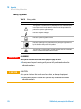
Safety Notices
CAUTION
A CAUTION notice denotes a
hazard. It calls attention to an
operating procedure, practice, or
the like that, if not correctly performed or adhered to, could
result in damage to the product
or loss of important data. Do not
proceed beyond a CAUTION
notice until the indicated conditions are fully understood and
met.
Technology Licenses
The hardware and/or software described in
this document are furnished under a license
and may be used or copied only in accordance with the terms of such license.
Restricted Rights Legend
If software is for use in the performance of a
U.S. Government prime contract or subcontract, Software is delivered and licensed as
“Commercial computer software” as
defined in DFAR 252.227-7014 (June 1995),
or as a “commercial item” as defined in FAR
2.101(a) or as “Restricted computer software” as defined in FAR 52.227-19 (June
1987) or any equivalent agency regulation
or contract clause. Use, duplication or disclosure of Software is subject to Agilent
Technologies’ standard commercial license
terms, and non-DOD Departments and
Agencies of the U.S. Government will
WA R N I N G
A WARNING notice denotes a
hazard. It calls attention to an
operating procedure, practice,
or the like that, if not correctly
performed or adhered to, could
result in personal injury or
death. Do not proceed beyond a
WARNING notice until the indicated conditions are fully understood and met.
1260 Infinity Autosampler User Manual
Contents
Contents
1 Introduction
7
Introduction to the Autosampler 8
Sampling Sequence 10
Sampling Unit 14
Needle/Sample Transport Assembly 18
Advanced Operating Modes 20
Early Maintenance Feedback (EMF) 22
Electrical Connections 23
Interfaces 24
Setting the 8-bit Configuration Switch (On-Board LAN)
2 Site Requirements and Specifications
30
37
Site Requirements 38
Physical Specifications 41
Performance Specifications 42
3 Installing the Autosampler
43
Unpacking the Sampler 44
Optimizing the Stack Configuration 46
Installing the Autosampler 51
Installing a Thermostatted Autosampler
Flow Connections to the Sampler 58
Installing the Sample Tray 60
Transporting the Sampler 62
4 Using the Autosampler
54
63
Sample Trays 64
List of Recommended Plates and Closing Mat
List of Recommended Vials and Caps 67
Configure Well Plate Types 69
Turn ON and Initialization Steps 72
1260 Infinity Autosampler User Manual
65
3
Contents
5 Optimizing Performance
73
Optimizing Performance 74
Optimization for Lowest Carry-Over 75
Fast Injection Cycle and Low Delay Volume
Precise Injection Volume 84
Choice of Rotor Seal 86
Choice of Seat Capillary 87
6 Troubleshooting and Diagnostics
82
89
Agilent Lab Advisor Software 90
Overview of the Sampler’s Indicators and Test Functions 91
Status Indicators 93
Error Messages 95
Maintenance Functions 112
High Performance Autosampler Step Commands 114
Troubleshooting the Autosampler 117
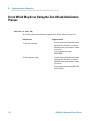
Errors Which May Occur During the Turn ON and Initialization Process
Instrument Logbook Errors and Step by Step Repair Proces 122
Needle Centering Over the Vial or the Well 128
7 Maintenance
118
129
Introduction to Maintenance and Repair 130
Maintenance Functions 132
Early Maintenance Feedback (EMF) 133
Maintenance Procedures 135
8 Parts and Materials for Maintenance
151
Sampler Main Assemblies 152
Vial Trays 154
Accessory Kits 156
Thermostat for ALS/FC/Spotter 157
9 Cable Identification
159
Cable Overview 160
Analog Cables 162
Remote Cables 164
4
1260 Infinity Autosampler User Manual
Contents
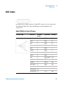
BCD Cables 167
CAN/LAN Cables 169
External Contact Cable 170
RS-232 Cables 171
10 Appendix
173
General Safety Information 174
The Waste Electrical and Electronic Equipment Directive
Lithium Batteries Information 178
Radio Interference 179
Sound Emission 180
Use of Solvents 181
Agilent Technologies on Internet 182
1260 Infinity Autosampler User Manual
177
5
Contents
6
1260 Infinity Autosampler User Manual
1260 Infinity Autosampler User Manual
1
Introduction
Introduction to the Autosampler
8
Sampling Sequence 10
Injection Sequence 12
Sampling Unit 14
Analytical Head 15
Injection-Valve 16
Needle Flush Station
Needle Lock 17
16
Needle/Sample Transport Assembly
Advanced Operating Modes
20
Early Maintenance Feedback (EMF)
Electrical Connections
Interfaces 24
Overview Interfaces
18
22
23
26
Setting the 8-bit Configuration Switch (On-Board LAN)
Communication Settings for RS-232C 33
Special Settings 35
30
This chapter gives an introduction to the High Performance Micro Autosampler.
Agilent Technologies
7
1
Introduction
Introduction to the Autosampler
Introduction to the Autosampler
The Agilent 1260 Infinity High Performance Micro Autosampler is designed
to perform capillary LC with injection of sample volumes ranging from nL to
µL.
Features: A micro Rheodyne® valve and the optimized design of the needle
seat, loop and seat capillaries minimize dispersion. A high-resolution metering
device offers resolution ten times better than a standard autosampler, bypass
operation facilitates low delay volume, increased sample injection speed for
high sample throughput, flexible and convenient sample handling with
different types of sample containers. Using 384-well plates allows to process
up to 768 samples unattended.
Technical Principle: The well plate sampler transport mechanism uses an
X-Z-theta robot to optimize the positioning of the sampling arm on the well
plate. Once the sampling arm is positioned over the programmed sample
position, the programmed sample volume is drawn by the metering device into
the sampling needle. The sampling arm then moves to the injection position
where the sample is flushed onto the column.
The autosamplers employ a vial/plate pusher mechanism to hold down the vial
or the plate while the needle is drawn back from the sample vessel (a must in
the case a septum is used). This vial/plate pusher employs a sensor to detect
the presence of a plate and to ensure accurate movement regardless of plate
used. All axes of the transport mechanism (x-,z-,theta-robot) are driven by
stepper-motors. Optical encoders ensure the correct operation of the
movement.
The micro metering device provides injection volumes from 0.01 – 8 µL with
the standard loop capillary installed and from 0.01 – 40 µL with the extended
loop capillary. The entire flowpath including the metering device is always
flushed by the mobile phase after injection for minimum internal carry-over.
An additional needle flush station with a peristaltic pump is installed to wash
the outside of the needle. This reduces the already low carry-over for very
sensitive analysis. The bottle containing the mobile phase for the wash
procedure will be located in the solvent bottle cabinet. Produced waste during
this operation is channeled safely away through a waste drain.
8
1260 Infinity Autosampler User Manual
Introduction
Introduction to the Autosampler
1
The six-port (only 5 ports are used) injection valve unit is driven by a
high-speed hybrid stepper motor. During the sampling sequence, the valve unit
bypasses the autosampler, and connects flow from the pump to the column
directly. During injection and analysis, the valve unit directs the flow through
the autosampler which ensures that all of the sample is injected onto the
column, and that the metering unit and needle are always free from sample
residue before the next sampling sequence begins. All the injection valves have
different stator heads and different rotor seals. The volume of each valve is
different.
Control of the vial/plate temperature in the thermostatted autosampler is
achieved using an additional Agilent module; the Agilent 1290 Infinity
Thermostat for ALS/FC/Spotter.
The thermostat contains Peltier-controlled heat-exchangers. A fan draws air
from the area above the sample vial tray of the autosampler. It is then blown
through the fins of the cooling/heating module. There it is cooled or heated
according the temperature setting. The thermostatted air enters the
autosampler through a recess underneath the special designed sample tray.
The air is then distributed evenly through the sample tray ensuring effective
temperature control, regardless of how many vials are in the tray. In cooling
mode condensation is generated on the cooled side of the Peltier elements.
This condensed water is safely guided into a waste bottle for condensed water.
1260 Infinity Autosampler User Manual
9
1
Introduction
Sampling Sequence
Sampling Sequence
HVbeaZigVchedgi
BIEWdVgY
AddeXVe^aaVgn
HVbea^c\jc^i
>aajb^cVi^dc@^i
EdlZghjeean
6cVani^XVa]ZVY
EZg^hiVai^Xejbe
K^VaigVn
Hl^iX]^c\kVakZ
CZZYaZ
CZZYaZhZVi
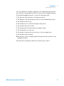
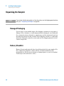
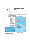
Figure 1
Overview of the autosampler
The movements of the autosampler components during the sampling sequence
are monitored continuously by the autosampler processor. The processor
defines specific time windows and mechanical ranges for each movement. If a
specific step of the sampling sequence is not completed successfully, an error
message is generated. Solvent is bypassed from the autosampler by the
injection valve during the sampling sequence. The needle moves to the desired
sample vial position and is lowered into the sample liquid in the vial to allow
the metering device to draw up the desired volume by moving its plunger back
a certain distance. The needle is then raised again and moved onto the seat to
10
1260 Infinity Autosampler User Manual
Introduction
Sampling Sequence
1
close the sample loop. Sample is applied to the column when the injection
valve returns to the mainpass position at the end of the sampling sequence.
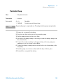
The standard sampling sequence occurs in the following order:
1 The injection valve switches to the bypass position.
2 The plunger of the metering device moves to the initialization position.
3 The needle lock moves up.
4 The needle moves to the desired sample vial position.
5 The needle lowers into the vial.
6 The metering device draws the preset sample volume.
7 The needle lifts out of the vial.
8 The needle is then moved onto the seat to close the sample loop.
9 The needle lock moves down.
10 The injection cycle is completed when the injection valve switches to the
mainpass position.
If needle wash is required it will be done between step 7 and 8.
1260 Infinity Autosampler User Manual
11
1
Introduction
Sampling Sequence
Injection Sequence
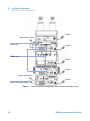
Before the start of the injection sequence, and during an analysis, the injection
valve is in the mainpass position (Figure 2 on page 12). In this position, the
mobile phase flows through the autosampler metering device, sample loop,
and needle, ensuring all parts in contact with sample are flushed during the
run, thus minimizing carry-over
Figure 2
Mainpass Position
When the sample sequence begins, the valve unit switches to the bypass
position (Figure 3 on page 12). Solvent from the pump enters the valve unit at
port 1, and flows directly to the column through port 6.
Figure 3
12
Bypass Position
1260 Infinity Autosampler User Manual
Introduction
Sampling Sequence
1
The standard injection starts with „draw sample from vial”. In order to do this
the needle moves to the desired sample vial position and is lowered into the
sample liquid in the vial to allow the metering device to draw up the desired
volume by moving its plunger back a certain distance. The needle is then
raised again and moved onto the seat to close the sample loop. In case of an
injector program several steps are interspersed at this point.
Figure 4
Drawing the Sample
Flush the Needle
Before injection and to reduce the carry-over for very sensitive analysis, the
outside of the needle can be washed in a flush port located behind the injector
port on the sampling unit. As soon the needle is on the flush port a peristaltic
pump delivers some solvent during a defined time to clean the outside of the
needle. At the end of this process the needle returns to the injection port.
Inject-and-Run
The final step is the inject-and-run step. The six-port valve is switched to the
main-pass position, and directs the flow back through the sample loop, which
now contains a certain amount of sample. The solvent flow transports the
sample onto the column, and separation begins. This is the beginning of a
„run” within an analysis. In this stage, all major performance-influencing
hardware is flushed internally by the solvent flow. For standard applications
no additional flushing procedure is required.
1260 Infinity Autosampler User Manual
13
1
Introduction
Sampling Unit
Sampling Unit
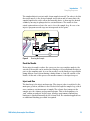
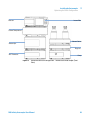
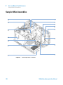
The sampling unit consists of subsystems as well. The main carrier part is a
die casting part which carries the following functional elements.
CZZYaZYg^kZ
CZZYaZadX`
6cVani^XVa]ZVY
;ajh]edgi
EZg^hiVai^Xejbe
CZZYaZhZVi
>c_ZXi^dckVakZ
Figure 5
14
Sampling unit
1260 Infinity Autosampler User Manual
Introduction
Sampling Unit
1
Analytical Head
The analytical head is driven by the stepper motor connected to the drive shaft
by a toothed belt. The drive nut on the spindle converts the circular movement
of the spindle to linear motion. The drive nut pushes the sapphire plunger
against the tension of the spring into the analytical head. The base of the
plunger sits on the large bearing of the drive nut, which ensures the plunger is
always centered. A ceramic ring guides the movement of the plunger in the
analytical head. The home position of the plunger is sensed by an infra-red
sensor on the sampling unit flex board, while the sample volume is determined
by counting the number of steps from the home position (7 nl/motor step). The
backward movement of the plunger (driven by the spring) draws sample from
the vial.
To reduce potential user mistakes different versions of analytical heads are
recognized by RF-tags sitting on the exchangeable assembly.
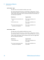
Table 1
Analytical head Technical Data
Standard 100 µl
(G1367-60003)
High Pressure 40µl
(G1377-60023)
Micro 40 µl
(G1377-60013)
Number of steps
15000
15000
60000
Volume resolution
14 nl/motor step
5.6 nl/motor step
1.4 nl/motor step
Maximum stroke
100 µl
40 µl
40 µl
Pressure limit
400 bars
600 bars
400 bars
Plunger material
Sapphire
Sapphire
Sapphire
1260 Infinity Autosampler User Manual
15
1
Introduction
Sampling Unit
Injection-Valve
A high pressure 6-port/2-position-valve to direct streams of mobile phase and
sample to different directions (e.g. via loop to column or directly to column).
The two-position 6-port injection valve is driven by a stepper motor. Only five
of the six ports are used (port 3 is not used). A lever/slider mechanism
transfers the movement of the stepper motor to the injection valve. Two
microswitches monitor switching of the valve (bypass and mainpass end
positions). The injection valve has a ceramic stator, Vespel rotor seal (Tefzel
seal available), and stainless-steel head. Three screws hold the head and
internal components in place. No valve adjustments are required after
replacing internal components.
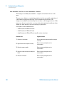
Table 2
Injection-Valve Technical Data
Standard (0101-0921)
Micro (0101-1050)
High pressure (0101-1422)
Motor type
4 V, 1.2 A stepper motor
4 V, 1.2 A stepper motor
4 V, 1.2 A stepper motor
Seal material
Vespel™ or Tefzel™
Vespel™
PEEK
Stator material
Ceramic/PEEK
Head coated SST
Ultralife
Number of ports
6
6
6
Switching time
< 150 ms
< 150 ms
< 150 ms
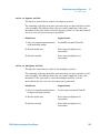
Needle Flush Station
A needle flush station to wash the outer surface of the injection needle and a
peristaltic pump to deliver fresh solvent to the wash station. (The reservoir for
the solvent is located in the solvent cabinet, the waste is channeled by a
separate flex tube to a waste bottle.
16
1260 Infinity Autosampler User Manual
Introduction
Sampling Unit
1
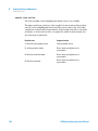
Needle Lock
A needle lock is used to support the needle carrier in its function making a
firm seal of the needle in its seat.
The needle lock arm is driven by a stepper motor connected to the spindle
assembly by a toothed belt.
1260 Infinity Autosampler User Manual
17
1
Introduction
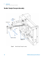
Needle/Sample Transport Assembly
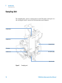
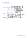
Needle/Sample Transport Assembly
Z VV h
I]ZiVVm^h
CZZYaZXVgg^Zg
M"Vm^h
O"Vm^h
CZZYaZVhhZbWan
GZ[aZXi^kZa^\]i
hl^iX]Zh
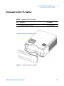
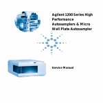
Figure 6
18
Needle/Sample Transport Assembly
1260 Infinity Autosampler User Manual
1
Introduction
Needle/Sample Transport Assembly
The needle/sample transport is a multifunctional module capable of moving
the needle into various positions (such as different wells in two different
plates, different vials, needle wash position and the needle-seat position). The
active movable axes are the X-axis, the Z-axis and the theta-axis, the
vial-/plate pusher is an additional passive axis. All axes are stepper motor
driven and encoder controlled in order to have tight feedback for the axes
position. The theta and Z axes have spring loaded belt-tensioner.
Reflective light switches detect the presence and type of different trays. The
X-slide carries the antenna and electronics of a RF-sensor. This device has
multiple functions:
• It allows to read and write information from a tag, located in the new tray.
• It allows to increase the number of different trays.
• It allows to read the revision and other data tags of the needle/sample
transport assembly and sampling unit.
Complex flex boards make the electrical connection to the various motors,
sensors and the MTP-board. The needle carrier has an integrated plate/vial
pusher with an additional linear encoder to sense vials and the presence of
plates.
The needle and the loop capillary are user-exchangeable.
The back of the needle/sample transport assembly has a cover to protect the
electronics from potential solvent vapor.
1260 Infinity Autosampler User Manual
19
1
Introduction
Advanced Operating Modes
Advanced Operating Modes
Multi-Draw Mode (Optional)
The multi-draw mode provides injection volumes up to 1500 µl. In this case a
capillary which holds the additional volume is assembled between seat and
valve. Then the aspirated sample is pushed into the enlarged seat capillary
before repetitive aspiration starts. After the last aspiration took place the
injection valve switches and the mobile phase transports sample towards
column.
Injector Program
A sequence of all available single sampling steps can be tailored to customer
needs for special applications. Injector program capability is offered with the
standard instrument
Active Needle Wash
The active needle wash mode allows also the flushing of the outer surface of
the needle. This results in an additional decrease of sample carry-over.
Duration of the procedure is setable.
Overlap Injection Cycle
Overlapped injection is the mode where the autosampler runs the injector
program for the next analysis during the current analysis (without injecting).
After the sample has reached the column the valve is switched back to bypass
and the next injection cycle starts but waits with switching to main-pass until
the actual run is finished. This mode allows it to increase the sample
throughput.
20
1260 Infinity Autosampler User Manual
1
Introduction
Advanced Operating Modes
Low Delay Volume Mode
This mode is especially interesting for gradient elution with small bore or
capillary columns. The injection valve is switched back to bypass after the
sample is eluted beyond the injection valve port # 6. This decreases the delay
volume, because the gradient needs not to pass the metering device and the
loop capillary.
1260 Infinity Autosampler User Manual
21
1
Introduction
Early Maintenance Feedback (EMF)
Early Maintenance Feedback (EMF)
The early maintenance feedback (EMF) feature monitors the usage of specific
components in the instrument, and provides feedback when the user-settable
limits have been exceeded. The visual feedback in the user interface provides
an indication that maintenance procedures should be scheduled.
For details on EMF counters and how to use them, see Agilent Lab Advisor.
22
1260 Infinity Autosampler User Manual
Introduction
Electrical Connections
1
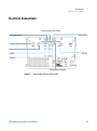
Electrical Connections
86CXVWaZidegZk^djhbdYjaZ
K^VacjbWZgdjieji
GZaVnXdciVXih
8dcigdad[I]ZgbdhiVi
GZbdiZ
98"Dji
GH'('8
86C"Wjh
86CXVWaZidcZmibdYjaZ
Figure 7
Autosampler Electrical Connections
1260 Infinity Autosampler User Manual
23
1
Introduction
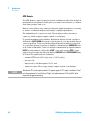
Interfaces
Interfaces
The Agilent 1200 Infinity Series modules provide the following interfaces:
Table 3
Agilent 1200 Infinity Series Interfaces
Module
CAN
LAN/BCD
(optional)
LAN
(on-board)
RS-232
Analog
APG
Remote
Special
G1310B Iso Pump
G1311B Quat Pump
G1311C Quat Pump VL
G1312B Bin Pump
G1312C Bin Pump VL
1376A Cap Pump
G2226A Nano Pump
2
Yes
No
Yes
1
Yes
G4220A/B Bin Pump
2
No
Yes
Yes
No
Yes
G1361A Prep Pump
2
Yes
No
Yes
No
Yes
CAN-DC- OUT for CAN
slaves
G1329B ALS
G2260A Prep ALS
2
Yes
No
Yes
No
Yes
THERMOSTAT for
G1330B
G1364B FC-PS
G1364C FC-AS
G1364D FC-μS
G1367E HiP ALS
G1377A HiP micro ALS
G2258A DL ALS
2
Yes
No
Yes
No
Yes
THERMOSTAT for
G1330B
CAN-DC- OUT for CAN
slaves
G4226A ALS
2
Yes
No
Yes
No
Yes
G1314B VWD VL
G1314C VWD VL+
2
Yes
No
Yes
1
Yes
G1314E/F VWD
2
No
Yes
Yes
1
Yes
Pumps
Samplers
Detectors
24
1260 Infinity Autosampler User Manual
Introduction
Interfaces
Table 3
1
Agilent 1200 Infinity Series Interfaces
Module
CAN
LAN/BCD
(optional)
LAN
(on-board)
RS-232
Analog
APG
Remote
Special
G4212A/B DAD
2
No
Yes
Yes
1
Yes
G1315C DAD VL+
G1365C MWD
G1315D DAD VL
G1365D MWD VL
2
No
Yes
Yes
2
Yes
G1321B FLD
G1362A RID
2
Yes
No
Yes
1
Yes
G4280A ELSD
No
No
No
Yes
Yes
Yes
G1316A/C TCC
2
No
No
Yes
No
Yes
G1322A DEG
No
No
No
No
No
Yes
AUX
G1379B DEG
No
No
No
Yes
No
No
AUX
G4227A Flex Cube
2
No
No
No
No
No
G4240A CHIP CUBE
2
Yes
No
Yes
No
Yes
EXT Contact
AUTOZERO
Others
NOTE
CAN-DC- OUT for CAN
slaves
THERMOSTAT for
G1330A/B (NOT USED)
The detector (DAD/MWD/FLD/VWD/RID) is the preferred access point for control via
LAN. The inter-module communication is done via CAN.
• CAN connectors as interface to other modules
• LAN connector as interface to the control software
• RS-232C as interface to a computer
• REMOTE connector as interface to other Agilent products
• Analog output connector(s) for signal output
1260 Infinity Autosampler User Manual
25
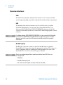
1
Introduction
Interfaces
Overview Interfaces
CAN
The CAN is inter-module communication interface. It is a 2-wire serial bus
system supporting high speed data communication and real-time requirement.
LAN
The modules have either an interface slot for an LAN card (e.g. Agilent
G1369A/B LAN Interface) or they have an on-board LAN interface (e.g.
detectors G1315C/D DAD and G1365C/D MWD). This interface allows the
control of the module/system via a connected PC with the appropriate control
software.
NOTE
If an Agilent detector (DAD/MWD/FLD/VWD/RID) is in the system, the LAN should be
connected to the DAD/MWD/FLD/VWD/RID (due to higher data load). If no Agilent
detector is part of the system, the LAN interface should be installed in the pump or
autosampler.
RS-232C (Serial)
The RS-232C connector is used to control the module from a computer
through RS-232C connection, using the appropriate software. This connector
can be configured with the configuration switch module at the rear of the
module. Refer to Communication Settings for RS-232C.
NOTE
There is no configuration possible on main boards with on-board LAN. These are
pre-configured for
• 19200 baud,
• 8 data bit with no parity and
• one start bit and one stop bit are always used (not selectable).
26
1260 Infinity Autosampler User Manual
1
Introduction
Interfaces
The RS-232C is designed as DCE (data communication equipment) with a
9-pin male SUB-D type connector. The pins are defined as:
Table 4
RS-232C Connection Table
Pin
Direction
Function
1
In
DCD
2
In
RxD
3
Out
TxD
4
Out
DTR
5
Ground
6
In
DSR
7
Out
RTS
8
In
CTS
9
In
RI
>chigjbZci
BVaZ
Figure 8
E8
;ZbVaZ
;ZbVaZ BVaZ
RS-232 Cable
Analog Signal Output
The analog signal output can be distributed to a recording device. For details
refer to the description of the module’s main board.
1260 Infinity Autosampler User Manual
27
1
Introduction
Interfaces
APG Remote
The APG Remote connector may be used in combination with other analytical
instruments from Agilent Technologies if you want to use features as common
shut down, prepare, and so on.
Remote control allows easy connection between single instruments or systems
to ensure coordinated analysis with simple coupling requirements.
The subminiature D connector is used. The module provides one remote
connector which is inputs/outputs (wired- or technique).
To provide maximum safety within a distributed analysis system, one line is
dedicated to SHUT DOWN the system’s critical parts in case any module detects
a serious problem. To detect whether all participating modules are switched
on or properly powered, one line is defined to summarize the POWER ON state
of all connected modules. Control of analysis is maintained by signal readiness
READY for next analysis, followed by START of run and optional STOP of run
triggered on the respective lines. In addition PREPARE and START REQUEST may
be issued. The signal levels are defined as:
• standard TTL levels (0 V is logic true, + 5.0 V is false),
• fan-out is 10,
• input load is 2.2 kOhm against + 5.0 V, and
• output are open collector type, inputs/outputs (wired- or technique).
NOTE
28
All common TTL circuits operate with a 5 V power supply. A TTL signal is defined as "low"
or L when between 0 V and 0.8 V and "high" or H when between 2.0 V and 5.0 V (with
respect to the ground terminal).
1260 Infinity Autosampler User Manual
Introduction
Interfaces
Table 5
1
Remote Signal Distribution
Pin
Signal
Description
1
DGND
Digital ground
2
PREPARE
(L) Request to prepare for analysis (for example, calibration, detector
lamp on). Receiver is any module performing pre-analysis activities.
3
START
(L) Request to start run / timetable. Receiver is any module
performing run-time controlled activities.
4
SHUT DOWN
(L) System has serious problem (for example, leak: stops pump).
Receiver is any module capable to reduce safety risk.
5
Not used
6
POWER ON
(H) All modules connected to system are switched on. Receiver is any
module relying on operation of others.
7
READY
(H) System is ready for next analysis. Receiver is any sequence
controller.
8
STOP
(L) Request to reach system ready state as soon as possible (for
example, stop run, abort or finish and stop injection). Receiver is any
module performing run-time controlled activities.
9
START REQUEST
(L) Request to start injection cycle (for example, by start key on any
module). Receiver is the autosampler.
Special Interfaces
Some modules have module specific interfaces/connectors. They are described
in the module documentation.
1260 Infinity Autosampler User Manual
29
1
Introduction
Setting the 8-bit Configuration Switch (On-Board LAN)
Setting the 8-bit Configuration Switch (On-Board LAN)
The 8-bit configuration switch is located at the rear of the module. Switch
settings provide configuration parameters for LAN, serial communication
protocol and instrument specific initialization procedures.
All modules with on-board LAN, e.g. G1315/65C/D, G1314D/E/F, G4212A/B,
G4220A:
• Default is ALL switches DOWN (best settings) - Bootp mode for LAN.
• For specific LAN modes switches 3-8 must be set as required.
• For boot/test modes switches 1+2 must be UP plus required mode.
Figure 9
NOTE
30
Location of Configuration Switch (example shows a G4212A DAD)
To perform any LAN configuration, SW1 and SW2 must be set to OFF. For details on the
LAN settings/configuration refer to chapter LAN Configuration.
1260 Infinity Autosampler User Manual
Introduction
Setting the 8-bit Configuration Switch (On-Board LAN)
Table 6
1
8-bit Configuration Switch (with on-board LAN)
Mode
Function
SW 1
SW 2
0
0
LAN
SW 3
SW 4
SW 5
SW 6
Link Configuration
SW 7
SW 8
Init Mode Selection
Auto-negotiation
0
x
x
x
x
x
10 MBit, half-duplex
1
0
0
x
x
x
10 MBit, full-duplex
1
0
1
x
x
x
100 MBit, half-duplex
1
1
0
x
x
x
100 MBit, full-duplex
1
1
1
x
x
x
Bootp
x
x
x
0
0
0
Bootp & Store
x
x
x
0
0
1
Using Stored
x
x
x
0
1
0
Using Default
x
x
x
0
1
1
TEST
1
1
System
NVRAM
Boot Resident System
1
x
Revert to Default Data (Coldstart)
x
x
x
1
Legend:
0 (switch down), 1 (switch up), x (any position)
NOTE
When selecting the mode TEST, the LAN settings are: Auto-Negotiation & Using Stored.
NOTE
For explanation of "Boot Resident System" and "Revert to Default Data (Coldstart)" refer to
“Special Settings” on page 35.
1260 Infinity Autosampler User Manual
31
1
Introduction
Setting the 8-bit Configuration Switch (On-Board LAN)
Setting the 8-bit Configuration Switch (without On-Board LAN)
The 8-bit configuration switch is located at the rear of the module.
Modules that do not have their own LAN interface (e.g. the TCC) can be
controlled through the LAN interface of another module and a CAN
connection to that module.
Figure 10
Configuration switch (settings depend on configured mode)
All modules without on-board LAN:
• default is ALL DIPS DOWN (best settings) - Bootp mode for LAN
• for boot/test modes DIPS 1+2 must be UP plus required mode
Switch settings provide configuration parameters for GPIB address, serial
communication protocol and instrument specific initialization procedures.
32
NOTE
With the introduction of the Agilent 1260 Infinity, all GPIB interfaces have been removed.
The preferred communication is LAN.
NOTE
The following tables represent the configuration switch settings for the modules without
on-board LAN only.
1260 Infinity Autosampler User Manual
1
Introduction
Setting the 8-bit Configuration Switch (On-Board LAN)
Table 7
NOTE
8-bit Configuration Switch (without on-board LAN)
Mode Select
1
2
RS-232C
0
1
Reserved
1
0
TEST/BOOT
1
1
3
4
5
Baudrate
6
7
Data
Bits
8
Parity
Reserved
RSVD
SYS
RSVD
RSVD
FC
The LAN settings are done on the LAN Interface Card G1369A/B. Refer to the
documentation provided with the card.
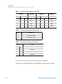
Communication Settings for RS-232C
The communication protocol used in the column compartment supports only
hardware handshake (CTS/RTR).
Switches 1 in down and 2 in up position define that the RS-232C parameters
will be changed. Once the change has been completed, the column instrument
must be powered up again in order to store the values in the non-volatile
memory.
Table 8
Communication Settings for RS-232C Communication (without on-board LAN)
Mode
Select
1
2
RS-232C
0
1
3
4
Baudrate
5
6
Data Bits
7
8
Parity
Use the following tables for selecting the setting which you want to use for
RS-232C communication. The number 0 means that the switch is down and 1
means that the switch is up.
1260 Infinity Autosampler User Manual
33
1
Introduction
Setting the 8-bit Configuration Switch (On-Board LAN)
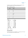
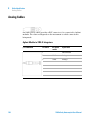
Table 9
Baudrate Settings (without on-board LAN)
Switches
Baud Rate
3
4
5
0
0
0
0
0
0
0
Table 10
Switches
Baud Rate
3
4
5
9600
1
0
0
9600
1
1200
1
0
1
14400
1
0
2400
1
1
0
19200
1
1
4800
1
1
1
38400
Data Bit Settings (without on-board LAN)
Switch 6
Data Word Size
0
7 Bit Communication
1
8 Bit Communication
Table 11
Parity Settings (without on-board LAN)
Switches
Parity
7
8
0
0
No Parity
1
0
Odd Parity
1
1
Even Parity
One start bit and one stop bit are always used (not selectable).
Per default, the module will turn into 19200 baud, 8 data bit with no parity.
34
1260 Infinity Autosampler User Manual
1
Introduction
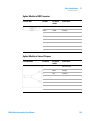
Setting the 8-bit Configuration Switch (On-Board LAN)
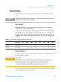
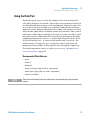
Special Settings
The special settings are required for specific actions (normally in a service
case).
NOTE
The tables include both settings for modules – with on-board LAN and without on-board
LAN. They are identified as LAN and no LAN.
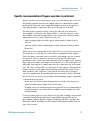
Boot-Resident
Firmware update procedures may require this mode in case of firmware
loading errors (main firmware part).
If you use the following switch settings and power the instrument up again,
the instrument firmware stays in the resident mode. It is not operable as a
module. It only uses basic functions of the operating system for example, for
communication. In this mode the main firmware can be loaded (using update
utilities).
Table 12
Boot Resident Settings (without on-board LAN)
Mode Select
SW1
SW2
SW3
SW4
SW5
SW6
SW7
SW8
LAN
TEST/BOOT
1
1
1
0
0
0
0
0
No LAN
TEST/BOOT
1
1
0
0
1
0
0
0
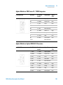
Forced Cold Start
A forced cold start can be used to bring the module into a defined mode with
default parameter settings.
CAUTION
Loss of data
Forced cold start erases all methods and data stored in the non-volatile memory.
Exceptions are diagnosis and repair log books which will not be erased.
➔ Save your methods and data before executing a forced cold start.
If you use the following switch settings and power the instrument up again, a
forced cold start has been completed.
1260 Infinity Autosampler User Manual
35
1
Introduction
Setting the 8-bit Configuration Switch (On-Board LAN)
Table 13
Forced Cold Start Settings (without on-board LAN)
Mode Select
SW1
SW2
SW3
SW4
SW5
SW6
SW7
SW8
LAN
TEST/BOOT
1
1
0
0
0
0
0
1
No LAN
TEST/BOOT
1
1
0
0
1
0
0
1
36
1260 Infinity Autosampler User Manual
1260 Infinity Autosampler User Manual
2
Site Requirements and Specifications
Site Requirements 38
Power Consideration
Power Cords 39
Bench Space 40
Condensation 40
Physical Specifications
38
41
Performance Specifications
42
This chapter describes the site requirements and specifications of the High
Performance Micro Autosampler.
Agilent Technologies
37
2
Site Requirements and Specifications
Site Requirements
Site Requirements
A suitable environment is important to ensure optimum performance of the
instrument.
Power Consideration
The autosampler power supply has wide-ranging capability (see Table 14 on
page 41). Consequently there is no voltage selector in the rear of the
autosampler. There are also no externally accessible fuses, because automatic
electronic fuses are implemented in the power supply.
The thermostatted autosampler comprises two modules, the sampler
(G1367B/D or G1377A) and the thermostat (G1330B). Both modules have a
separate power supply and a power plug for the line connections. The two
modules are connected by a control cable and both are turned on by the
sampler module. The thermostat power supply has two externally accessible
fuses.
WA R N I N G
Damaged electronics
Disconnecting or reconnecting the sampler to thermostat cable when the power
cords are connected to either of the two modules will damage the electronics of the
modules.
➔ Make sure the power cords are unplugged before disconnecting or reconnecting the
sampler to thermostat cable.
WA R N I N G
Incorrect line voltage at the instrument
Shock hazard or damage of your instrumentation can result, if the devices are
connected to a line voltage higher than specified.
➔ Connect your instrument to the specified line voltage.
38
1260 Infinity Autosampler User Manual
2
Site Requirements and Specifications
Site Requirements
CAUTION
Unaccessable power plug.
In case of emergency it must be possible to disconnect the instrument from the power
line at any time.
➔ Make sure the power connector of the instrument can be easily reached and
unplugged.
➔ Provide sufficient space behind the power socket of the instrument to unplug the
cable.
Power Cords
Different power cords are offered as options with the module. The female end
of all power cords is identical. It plugs into the power-input socket at the rear.
The male end of each power cord is different and designed to match the wall
socket of a particular country or region.
WA R N I N G
Absence of ground connection or use of unspecified power cord
The absence of ground connection or the use of unspecified power cord can lead to
electric shock or short circuit.
➔ Never operate your instrumentation from a power outlet that has no ground
connection.
➔ Never use a power cord other than the Agilent Technologies power cord designed
for your region.
WA R N I N G
Use of unsupplied cables
Using cables not supplied by Agilent Technologies can lead to damage of the
electronic components or personal injury.
➔ Never use cables other than the ones supplied by Agilent Technologies to ensure
proper functionality and compliance with safety or EMC regulations.
1260 Infinity Autosampler User Manual
39
2
Site Requirements and Specifications
Site Requirements
WA R N I N G
Unintended use of supplied power cords
Using power cords for unintended purposes can lead to personal injury or damage of
electronic equipment.
➔ Never use the power cords that Agilent Technologies supplies with this instrument
for any other equipment.
Bench Space
The module dimensions and weight (see Table 14 on page 41) allow you to
place the module on almost any desk or laboratory bench. It needs an
additional 2.5 cm (1.0 inches) of space on either side and approximately 8 cm
(3.1 inches) in the rear for air circulation and electric connections.
If the bench should carry an Agilent system, make sure that the bench is
designed to bear the weight of all modules.
The module should be operated in a horizontal position.
Condensation
CAUTION
Condensation within the module
Condensation will damage the system electronics.
➔ Do not store, ship or use your module under conditions where temperature
fluctuations could cause condensation within the module.
➔ If your module was shipped in cold weather, leave it in its box and allow it to warm
slowly to room temperature to avoid condensation.
40
1260 Infinity Autosampler User Manual
2
Site Requirements and Specifications
Physical Specifications
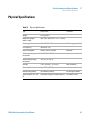
Physical Specifications
Table 14
Physical Specifications
Type
Specification
Weight
15.5 kg (35 lbs)
Dimensions (height ×
width × depth)
200 × 345 × 440 mm (8 × 13.5 × 17 inches)
Line voltage
100 – 240 VAC, ± 10%
Line frequency
50 or 60 Hz, ± 5%
Power consumption
300 VA / 200 W / 683 BTU
Ambient operating
temperature
4 – 55 °C (41 – 131 °F)
Ambient non-operating
temperature
-40–70 °C (-4–158 °F)
Humidity
< 95%, at 25–40 °C (77–104 °F)
Operating Altitude
Up to 2000 m (6562 ft)
Non-operating altitude
Up to 4600 m (15091 ft)
Safety standards: IEC, CSA,
UL
Installation Category II, Pollution Degree 2 For indoor use only.
1260 Infinity Autosampler User Manual
Comments
Wide-ranging capability
Maximum
Non-condensing
For storing the module
41
2
Site Requirements and Specifications
Performance Specifications
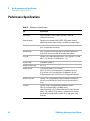
Performance Specifications
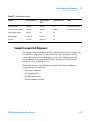
Table 15
42
Performance Specifications
Type
Specification
GLP features
Early maintenance feedback (EMF), electronic records of
maintenance and errors
Communications
Controller-area network (CAN). RS232C, APG-remote standard,
optional four external contact closures and BCD vial number output
Safety features
Leak detection and safe leak handling, low voltages in maintenance
areas, error detection and display
Injection range
0.01– 8 µl in 0.01 µl increments with the small loop capillary 0.01–
40 µl in 0.01 µl increments with the extended loop capillary
Precision
Typically < 0.5% RSD of peak areas from 5 – 40 µl, Typically < 1% RSD
from 1 – 5 µl Typically < 3% RSD from 0.2 – 1 µl
Pressure range
up to 400 bar (5880 psi)
Sample viscosity range
0.2 – 5 cp
Sample capacity
2 × well-plates (MTP) + 10 × 2 ml vials
108 x 2-mL vials in 2 x 54 vial plate plus 10 additional 2 mL vials
30 x 6-mL vials in 2 x 15 vial plate plus 10 additional 2 mL vials
54 Eppendorf tubes (0.5/1.5/2.0 mL) in 2 x 27 Eppendorf tube plate
Injection cycle time
Typically < 30 s using following standard conditions: Default draw
speed: 4 µl/min Default eject speed: 10 µl/min Injection volume:
0.1 µl
Carry-over
Typically < 0.05% using the following conditions: Column:
150 x 0.5 mm Hypersil ODS, 3 µm Mobile phase:
Water/Acetonitrile = 85/15 Column Flow rate: 13 µl/min Injection
volume: 1 µl caffeine (=25 ng caffeine), 1 µl water to test carryover
Outside wash of needle before injection: 20 sec with water using
flush port
1260 Infinity Autosampler User Manual
1260 Infinity Autosampler User Manual
3
Installing the Autosampler
Unpacking the Sampler 44
Damaged Packaging 44
Delivery Checklist 44
Accessory Kits 45
Optimizing the Stack Configuration
Installing the Autosampler
46
51
Installing a Thermostatted Autosampler
Flow Connections to the Sampler
Installing the Sample Tray
60
Transporting the Sampler
62
54
58
This chapter describes the installation of the High Performance Micro
Autosampler.
Agilent Technologies
43
3
Installing the Autosampler
Unpacking the Sampler
Unpacking the Sampler
NOTE
If you need to ship the autosampler at a later date, always use the shipping protection foam
parts (see “Transporting the Sampler” on page 62).
Damaged Packaging
Upon receipt of your module, inspect the shipping containers for any signs of
damage. If the containers or cushioning material are damaged, save them until
the contents have been checked for completeness and the instrument has been
mechanically and electrically checked. If the shipping container or cushioning
material is damaged, notify the carrier and save the shipping material for the
carrier’s inspection.
Delivery Checklist
Ensure all parts and materials have been delivered with the autosampler. For
this compare the shipment content with the checklist included in each
instrument box. Please report missing or damaged parts to your local Agilent
Technologies sales and service office.
44
1260 Infinity Autosampler User Manual
Installing the Autosampler
Unpacking the Sampler
3
Accessory Kits
p/n
Description
5063-6527
Tubing assembly, i.d. 6 mm, o.d. 9 mm, 1.2 m (to waste)
9222-0518
Bag - plastics
G1315-45003
Torque adapter
G1367-60006
WPS Leak Kit
G1375-87304
Fused silica/PEEK capillary 50 µm, 50 cm
G1375-87316
Seat Capillary (150 mm 0.075 mm ID) for G1377-87101 Needle Seat
G1329-43200
Adapter air channel
5181-1519
CAN cable, Agilent module to module, 1 m
8710-1534
Wrench, 4 mm both ends, open end
G1377-44900
tool for Micro Seat Capillary Mounting
G1377-87300
Loop capillary, 40 µL for G1377A
1260 Infinity Autosampler User Manual
45
3
Installing the Autosampler
Optimizing the Stack Configuration
Optimizing the Stack Configuration
If your autosampler is part of a system, you can ensure optimum performance,
ensuring minimum delay volume by installing the following configuration.
Figure 11 on page 47 and Figure 12 on page 48 show the configuration
recommended for the sampler. Figure 13 on page 49 and Figure 14 on page 50
show the configuration recommended for the thermostatted sampler.
46
1260 Infinity Autosampler User Manual
Installing the Autosampler
Optimizing the Stack Configuration
3
HdakZciXVW^cZi
KVXjjbYZ\VhhZg
Ejbe
>chiVciE^adi
6jidhVbeaZg
8dajbcXdbeVgibZci
9ZiZXidg
Figure 11
Recommended Stack Configuration - Well Plate Autosampler (Front View)
1260 Infinity Autosampler User Manual
47
3
Installing the Autosampler
Optimizing the Stack Configuration
68edlZg
6cVad\h^\cVaidgZXdgYZg
GZbdiZXVWaZ
68edlZg
86C7jhXVWaZ
68edlZg
68edlZg
6cVad\h^\cVaidgZXdgYZg
68edlZg
<E>7dgA6CidXdcigdahd[ilVgZ
Figure 12
48
Recommended Stack Configuration - Well Plate Autosampler (Rear View)
1260 Infinity Autosampler User Manual
Installing the Autosampler
Optimizing the Stack Configuration
3
>chiVciE^adi
9ZiZXidg
8dajbc8dbeVgibZci
HdakZci8VW^cZi
6jidhVbeaZg
9Z\VhhZg
6AHI]ZgbdhiVi
Ejbe
Figure 13
Recommended Stack Configuration - Thermostatted Autosampler (Front
View)
1260 Infinity Autosampler User Manual
49
3
Installing the Autosampler
Optimizing the Stack Configuration
6cVad\h^\cVa
idgZXdgYZg
86CWjhXVWaZ
<E>7dgA6C
idA88]ZbHiVi^dc
68edlZg
68edlZg
6jidhVbeaZg"
I]ZgbdhiVi"XVWaZ
GZbdiZXVWaZ
6cVad\h^\cVa
idgZXdgYZg
Figure 14
50
68edlZg
68edlZg
68edlZg
68edlZg
Recommended Stack Configuration - Thermostatted Autosampler (Rear View)
1260 Infinity Autosampler User Manual
3
Installing the Autosampler
Installing the Autosampler
Installing the Autosampler
Parts required
Preparations
WA R N I N G
#
Description
1
Sampler Power cord.
•
Locate bench space Provide power connections Unpack the sampler
Instruments are partially energized when switched off
The power supplies still use some power, even if the power switch on the front panel
is turned off.
➔ To disconnect the thermostatted autosampler from line power, unplug the power
cord from the autosampler and the ALS thermostat.
➔ Make sure that it is always possible to access the power plug.
WA R N I N G
Personal injury
To avoid personal injury, keep fingers away from the needle area during autosampler
operation.
➔ Do not attempt to insert or remove a vial or a plate when the needle is positioned.
CAUTION
"Defective on arrival" problems
If there are signs of damage, please do not attempt to install the module. Inspection by
Agilent is required to evaluate if the instrument is in good condition or damaged.
➔ Notify your Agilent sales and service office about the damage.
➔ An Agilent service representative will inspect the instrument at your site and
initiate appropriate actions.
1260 Infinity Autosampler User Manual
51
3
Installing the Autosampler
Installing the Autosampler
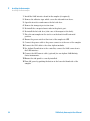
1 Install the LAN interface board in the sampler (if required).
2 Remove the adhesive tape which covers the side and front doors.
3 Open the front door and remove the left side door.
4 Remove the transport protection foam.
5 Re-install the corrugated waste tube in the plastic port.
6 Re-install the left side door (take care of the magnet at the back).
7 Place the autosampler in the stack or on the bench in all horizontal
position.
8 Ensure the power switch at the front of the sampler is OFF.
9 Connect the power cable to the power connector at the rear of the sampler.
10 Connect the CAN cable to the other Agilent modules.
11 If a Agilent ChemStation is the controller, connect the LAN connection to
the LAN interface
12 Connect the APG remote cable (optional) for non Agilent 1200 Infinity
Series instruments.
13 Ensure the side panel is correctly installed.
14 Turn ON power by pushing the button at the lower left hand side of the
sampler.
52
1260 Infinity Autosampler User Manual
Installing the Autosampler
Installing the Autosampler
3
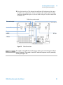
15 Close the front door. The exhaust fan will turn ON and remove the vapor
from the tray compartment. After 1-2 minutes the sampler will start the
hardware initialisation process. At the end of this process the status LED
should be off.
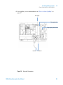
86CXVWaZidegZk^djhbdYjaZ
K^VacjbWZgdjieji
GZaVnXdciVXih
8dcigdad[I]ZgbdhiVi
GZbdiZ
98"Dji
GH'('8
86C"Wjh
86CXVWaZidcZmibdYjaZ
Figure 15
NOTE
Cable Connections
The sampler is turned ON when the line power switch is pressed and the green indicator
lamp is illuminated. The sampler is turned OFF when the line power switch is protruding
and the green light is OFF.
1260 Infinity Autosampler User Manual
53
3
Installing the Autosampler
Installing a Thermostatted Autosampler
Installing a Thermostatted Autosampler
Parts required
Preparations
WA R N I N G
#
Description
1
Sampler and thermostat Power cord.
•
Locate bench space Provide power connections Unpack the sampler and the thermostat
Instrument is partially energized when switched off
The power supply still uses some power, even if the power switch at the front of the
panel is turned off.
➔ To disconnect the sampler from the line, unplug the power cord.
CAUTION
Damaged electronics
Disconnecting or reconnecting the sampler to thermostat cable when the power cords
are connected to either of the two modules will damage the electronics of the modules.
➔ Make sure the power cords are unplugged before disconnecting or reconnecting the
sampler to thermostat cable.
CAUTION
Damage through condensation
If the condensation tube is located in liquid the condensed water cannot flow out of
the tube and the outlet is blocked. Any further condensation will then remain in the
instrument. This may damage the instruments electronics.
➔ Make sure that the condensation tube is always above the liquid level in the vessel.
WA R N I N G
Personal injury
To avoid personal injury, keep fingers away from the needle area during autosampler
operation.
➔ Do not attempt to insert or remove a vial or a plate when the needle is positioned.
54
1260 Infinity Autosampler User Manual
Installing the Autosampler
Installing a Thermostatted Autosampler
3
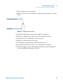
1 Place the thermostat on the bench.
2 Remove the front cover and route the condensation drain tube to the waste
bottle.
8dcYZchVi^dcYgV^cijWZ
LVhiZWdiiaZ
Figure 16
Condensation leak outlet
3 Install the LAN interface board in the sampler (if required).
4 Remove the adhesive tape which covers the side and front doors.
5 Open the front door and remove the left side door.
6 Remove the transport protection foam.
7 Re-install the corrugated waste tube in the plastic port.
8 Re-install the left side door (take care of the magnet at the back).
9 Place the sampler on top of the thermostat. Make sure that the sampler is
correctly engaged in the thermostat locks.
1260 Infinity Autosampler User Manual
55
3
Installing the Autosampler
Installing a Thermostatted Autosampler
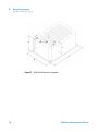
10 Remove the tray and the plastic cover from the tray base, place the air
channel adapter into the sampler tray base. Make sure the adapter is fully
pressed down. This assures that the cold airstream from the thermostat is
correctly guided to the tray area of the well plate sampler.
6^gX]VccZaVYVeiZg
Figure 17
Installation of Thermostat and Autosampler
11 Re-install the tray.
12 Ensure the power switch on the front of the sampler is 0FF and the power
cables are disconnected.
13 Connect the cable between the sampler and the thermostat, see Figure 18
on page 57.
14 Connect the power cables to the power connectors.
15 Connect the CAN cable to other Agilent modules.
16 If a Agilent ChemStation is the controller, connect the LAN connection to
the LAN interface
17 Connect the APG remote cable (optional) for non Agilent 1200 Infinity
Series instruments.
18 Ensure the side panel is correctly installed.
19 Turn ON power by pushing the button at the lower left hand side of the
sampler.
56
1260 Infinity Autosampler User Manual
Installing the Autosampler
Installing a Thermostatted Autosampler
3
20 Close the front door.
The exhaust fan will turn ON and remove the vapor from the tray
compartment. After 1-2 minutes the sampler will start tile hardware
initialisation process. At the end of this process the status LED should be
off.
HVbeaZg"I]ZgbdhiViXVWaZ
86C"Wjh
Figure 18
NOTE
68EdlZg
Connection at the rear of thermostatted Autosampler
The sampler is turned ON when the line power switch is pressed and the green indicator
lamp is illuminated. The sampler is turned 0FF when the line power switch is protruding and
the green light is 0FF.
1260 Infinity Autosampler User Manual
57
3
Installing the Autosampler
Flow Connections to the Sampler
Flow Connections to the Sampler
Parts required
Preparations
WA R N I N G
#
Description
1
Parts from the accessory kits, see “Accessory Kits” on page 45
•
Sampler is installed in the LC system
When opening capillary or tube fittings solvents may leak out.
The handling of toxic and hazardous solvents and reagents can bear health risks.
➔ Please observe appropriate safety procedures (for example, goggles, safety gloves
and protective clothing) as described in the material handling and safety data sheet
supplied by the solvent vendor, especially when toxic or hazardous solvents are
used.
1 Connect the pump outlet capillary to port 1 of the injection valve.
2 Connect column-compartment inlet capillary to port 6 of the injection
valve.
3 Connect the corrugated waste tube to the seat adapter and the solvent
waste from the leak plane.
4 Ensure that the waste tube is positioned inside the leak channel.
5 Drive the tube from the peristaltic flush pump to the solvent bottle in the
solvent cabinet
58
1260 Infinity Autosampler User Manual
Installing the Autosampler
Flow Connections to the Sampler
3
6 Seat capillary: see recommendations in “Choice of Seat Capillary” on
page 87
[gdbejbe
8dggj\ViZYijWZ
AddeXVe^aaVgnlVhiZijWZ
idlVhiZ
Figure 19
idXdajbc
Hydraulic Connections
1260 Infinity Autosampler User Manual
59
3
Installing the Autosampler
Installing the Sample Tray
Installing the Sample Tray
1 Press the bottom on the right side to release the front door.
2 Lift the front door.
3 Load the sample tray with sample well plates and vials as required.
4 Slide the sample tray into the autosampler so that the rear of the sample
tray is seated firmly against the rear of the sample-tray area.
5 Press the front of the sample tray down to secure the tray in the
autosampler.
NOTE
60
If the tray pops out of position the air channel adapter is not correctly inserted.
1260 Infinity Autosampler User Manual
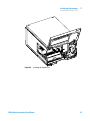
Installing the Autosampler
Installing the Sample Tray
Figure 20
3
Installing the Sample Tray
1260 Infinity Autosampler User Manual
61
3
Installing the Autosampler
Transporting the Sampler
Transporting the Sampler
When moving the autosampler inside the laboratory, no special precautions
are needed. However, if the autosampler needs to be shipped to another
location via carrier, ensure:
• The transport assembly is in the park position. Use the Lab Monitor and
Diagnostic software or the Instant Pilot for this command.
• The vial tray and the sample transport mechanism is secured with the
transport protection foam.
62
1260 Infinity Autosampler User Manual
1260 Infinity Autosampler User Manual
4
Using the Autosampler
Sample Trays
64
List of Recommended Plates and Closing Mat
List of Recommended Vials and Caps
Configure Well Plate Types
65
67
69
Turn ON and Initialization Steps
72
This chapter describes the usage of the High Performance Micro Autosampler.
Agilent Technologies
63
4
Using the Autosampler
Sample Trays
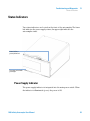
Sample Trays
Supported Trays for an Autosampler
Table 16
Trays for an Autosampler
G2258-60011
Tray for 2 well plates or vial plates and 10 x 2 ml vials
Edh#E'"6&
K^Va&%
Edh#E'"7&
EaViZ'
Edh#E'"E')
Edh#E&"6&
Edh#E&"7&
EaViZ&
Edh#E&"=&'
K^Va&
Figure 21
64
Numbering of vial and well plate position
1260 Infinity Autosampler User Manual
Using the Autosampler
List of Recommended Plates and Closing Mat
4
List of Recommended Plates and Closing Mat
WA R N I N G
Explosive gas mixtures
There is a risk of building explosive gas mixtures in the instrument if flammable
solvents are used.
➔ Cover the plates.
➔ Remove the plates from the sampler after turning it 0FF.
WA R N I N G
Contamination with adhesives
Closing mats with adhesive can give some contamination in the system. The
adhesive is soluble in most of the solvents used in HPLC.
➔ In general do not use closing mats with adhesive. The sampler has no prepunch
needle, therefore the adhesive will clog the needle after several injections.
1260 Infinity Autosampler User Manual
65
4
Using the Autosampler
List of Recommended Plates and Closing Mat
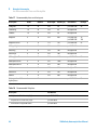
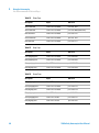
Table 17
Recommended plates and closing mat
Description
Rows
Columns
Plate height
Volume (µI)
Part Number
Package
384Agilent
16
24
14.4
80
p/n 5042-1388
30
384Corning
16
24
14.4
80
No Agilent PN
384Nunc
16
24
14.4
80
No Agilent PN
96Agilent
8
12
14.3
400
p/n 5042-1386
p/n 5042-1385
10
120
96Agilent conical
8
12
17.3
150
p/n 5042-8502
25
96CappedAgilent
8
12
47.1
300
p/n 5065-4402
1
96Corning
8
12
14.3
300
No Agilent PN
96CorningV
8
12
14.3
300
No Agilent PN
96DeepAgilent31mm
8
12
31.5
1000
p/n 5042-6454
96DeepNunc31mm
8
12
31.5
1000
No Agilent PN
96DeepRitter41mm
8
12
41.2
800
No Agilent PN
96Greiner
8
12
14.3
300
No Agilent PN
96GreinerV
8
12
14.3
250
No Agilent PN
96Nunc
8
12
14.3
400
No Agilent PN
Closing mat for all 96
Agilent plates
8
12
Table 18
p/n 5042-1389
50
Recommended Vial plates
Description
Part Number
•
Vial plate for 54 x 2 ml vials (6/pk)
p/n G2255-68700
•
Vial plate for 15 x 6 ml vials (1/pk)
p/n 5022-6539
•
Vial Plate for 27 Eppendorf tubes
p/n 5022-6538
66
50
1260 Infinity Autosampler User Manual
Using the Autosampler
List of Recommended Vials and Caps
4
List of Recommended Vials and Caps
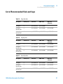
Table 19
Crimp Top Vials
Description
Volume (ml)
lOO/Pack
lOOO/Pack
Clear glass
2
p/n 5181-3375
p/n 5183-4491
Clear glass,
write-on spot
2
p/n 5182-0543
p/n 5183-4492
p/n 5183-4494
Amber glass,
write-on spot
2
p/n 5182-3376
p/n 5183-4493
p/n 5183-4495
Table 20
lOO/Pack
(silanized)
SnapTop Vials
Description
Volume (ml)
lOO/Pack
lOOO/Pack
lOO/Pack
(silanized)
Clear glass
2
p/n 5182-0544
p/n 5183-4504
p/n 5183-4507
Clear glass,
write-on spot
2
p/n 5182-0546
p/n 5183-4505
p/n 5183-4508
Amber glass,
write-on spot
2
p/n 5182-0545
p/n 5183-4506
p/n 5183-4509
Table 21
Screw Top Vials
Description
Volume (ml)
lOO/Pack
lOOO/Pack
lOO/Pack
(silanized)
Clear glass
2
p/n 5182-0714
p/n 5183-2067
p/n 5183-2070
Clear glass,
write-on spot
2
p/n 5182-0715
p/n 5183-2068
p/n 5183-2071
Amber glass,
write-on spot
2
p/n 5182-0716
p/n 5183-2069
p/n 5183-2072
1260 Infinity Autosampler User Manual
67
4
Using the Autosampler
List of Recommended Vials and Caps
Table 22
Description
Septa
100/Pack
Silver aluminum
Clear PTFE/red rubber
p/n 5181-1210
Silver aluminum
Clear PTFE/red rubber
p/n 5183-4498 (1000/Pack)
Blue aluminum
Clear PTFE/red rubber
p/n 5181-1215
Green aluminum
Clear PTFE/red rubber
p/n 5181-1216
Red aluminum
Clear PTFE/red rubber
p/n 5181-1217
Description
Septa
100/Pack
Clear polypropyIene
Clear PTFE/red rubber
p/n 5182-0550
BIue polypropylene
Clear PTFE/red rubber
p/n 5182-3458
Green polypropylene
Clear PTFE/red rubber
p/n 5182-3457
Red polypropylene
Clear PTFE/red rubber
p/n 5182-3459
Description
Septa
100/Pack
BIue polypropyIene
Clear PTFE/red rubber
p/n 5182-0717
Green polypropyIene
Clear PTFE/red rubber
p/n 5182-0718
Red polypropylene
Clear PTFE/red rubber
p/n 5182-0719
BIue polypropylene
Clear PTFE/silicone
p/n 5182-0720
Green polypropylene
Clear PTFE/silicone
p/n 5182-0721
Red polypropyIene
Clear PTFE/silicone
p/n 5182-0722
Table 23
Table 24
68
Crimp Caps
Snap Caps
Screw Caps
1260 Infinity Autosampler User Manual
Using the Autosampler
Configure Well Plate Types
4
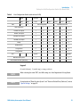
Configure Well Plate Types
If the plate you are using is not found on the “List of Recommended Plates and
Closing Mat” on page 65 you may configure a custom plate. Measure the exact
dimensions of the plate as marked below and enter the values in the plate
configuration table of the ChemStation.
Xdajbc
>
;
<
6
:
7
gdl
?
8
9
Figure 22
Well Plate Dimensions (straight)
1260 Infinity Autosampler User Manual
69
4
Using the Autosampler
Configure Well Plate Types
;
>
<
:
6
7
=
?
8
9
Figure 23
70
Well Plate Dimensions (staggered)
1260 Infinity Autosampler User Manual
Using the Autosampler
Configure Well Plate Types
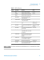
Table 25
Location
NOTE
4
Well Plate Dimensions
Description
Definition
Limits
Rows
Number of rows on the plate
up to 16
Columns
Number of columns on the plate
up to 24
Volume
Volume (in µI) of a sample vessel
A
Row distance
Distance (in mm) between the
center of two rows
B
Column distance
Distance (in mm) between the
center of two columns
C
Plate length
X size (in mm) at the bottom of the
plate
127.75+/- 0.25 mm
(SBS Standard)
D
Plate width
Y size (in mm) at the bottom of the
plate
85.50+/-0.25 mm (SBS
Standard)
E
Plate height
Size (in mm) from the bottom to the
top of the plate
up to 47 mm
F
Row offset
Distance (in mm) from the back
edge (bottom) to the center of the
first hole (A1)
G
Column offset
Distance (in mm) from the left edge
(bottom) to the center of the first
hole (A1)
H
Column shift
Offset (in mm) to Y when the rows
are not straight but staggered
l
Well diameter
Diameter (in mm) of the well
at least 4 mm
J
WeIl depth
Distance (in mm) from the top of the
plate to the bottom of the well
up to 45 mm
The distances need to be measured with high precision. It is recommended to use calipers.
1260 Infinity Autosampler User Manual
71
4
Using the Autosampler
Turn ON and Initialization Steps
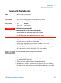
Turn ON and Initialization Steps
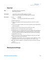
A successful turn-on/initialization takes about 3.5 minutes, and consists of
five steps
1 WPS turn on, begins when the main power button is pushed ON. Power
indicator turns green. Front cover latch activates immediately.
2 Main fan and exhaust fan turn-on immediately.
3 Main board self-test begins. Status indicator tests red, green and yellow,
then goes to yellow. This takes about 20 seconds (from turn-on). The status
indicator remains yellow until the initialization process is complete. The
user interface indicates “initializing” during this period.
4 The vapor blowout period begins. This lasts for about 2 minutes.
5 WPS sample transport and sampling unit initialization begins at the
2-minutes mark (from turn-on), if the front cover is closed. If the front cover
is open at the 2 minutes mark, initialization will start only when the front
cover is closed. Initialization takes about 1.5 minutes. When initialization is
complete the needle is in the needle seat, the needle lock is down, and the
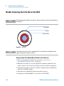
status indicator is off.
HiVijhA:9
EdlZgA:9
Figure 24
72
Instrument LED indicator
1260 Infinity Autosampler User Manual
1260 Infinity Autosampler User Manual
5
Optimizing Performance
Optimizing Performance
74
Optimization for Lowest Carry-Over 75
Using the Automated Needle Wash 78
Using the Flush Port 79
Cleaning the needle seat 80
Fast Injection Cycle and Low Delay Volume
82
Precise Injection Volume 84
Draw and Eject Speed 84
Choice of Rotor Seal
86
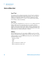
Choice of Seat Capillary
87
This chapter provides information on how to optimize the autosampler.
Agilent Technologies
73
5
Optimizing Performance
Optimizing Performance
Optimizing Performance
Autosamplers are more and more used in HPLC to improve the productivity in
the laboratories and the consistency and accuracy of analytical results.
The informations below will help you on how to optimize some parameters to
achieve best results for:
• lowest carry-over for reliable quantitative data
• Fast injection cycles for high throughput
• Low delay volume for fast gradient
• Precise injection volume
74
1260 Infinity Autosampler User Manual
Optimizing Performance
Optimization for Lowest Carry-Over
5
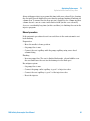
Optimization for Lowest Carry-Over
Carry over (CO) is not only a topic for injection systems but may have multiple
sources:
Hardware related
• sample loop
• needle outside
• needle inside
• needle seat
• seat capillary
• injection valve
• flush time
• wash vials
• fittings
• column (carry-over depends on frit design/material/blockage)
• surface activity of frits
• capillaries
Chemistry/Physics related:
• suitable sample solvent (has to be compatible with mobile phase)
• suitable wash solvent
• suitable mobile phase
• column packing material (e.g. interaction of basic sample with silanols of
stationary phase)
The autosampler continuous flow-through design ensures that sample loop,
needle inside, seat capillary, and the mainpass of the injection valve is always
in the flow line. These parts are continuously flushed during an isocratic and
also during a gradient analysis. The residual amount of sample remaining on
the outside of the needle after injection may contribute to carry-over in some
instances. When using small injection volumes or when injecting samples of
low concentration immediately after samples of high concentration, carry-over
may become noticeable. Cleaning the needle in the flush port or using the
automated needle wash enables the carry-over to be minimized and prevents
also contamination of the needle seat.
1260 Infinity Autosampler User Manual
75
5
Optimizing Performance
Optimization for Lowest Carry-Over
General recommendations for lowest carry-over
Issues in setting up the experiments:
• Use a flush solvent which dissolves the sample well (e.g. aqueous/(organic)
acidic for basic samples); set needle wash time to at least 10 sec.
• Use a sample solvent which is compatible with sample and mobile phase.
Organic sample solvents (e.g. DMSO) injected into aqueous mobile phase
often cause samples to partially deposit on surfaces causing high
carry-over. Chlorhexidine, for example, dissolved as a free base in methanol
and injected into an acidic aqueous mobile phase shows increased
carryover than if it is dissolved in 0.1% TFA. Since it dissolves slowly (but
well) in acidic aqueous solvents, it partially deposits on surfaces during the
injection cycle.
• Take care at loop capillary change: Push loop capillary forward when
tightening the fitting to the needle, ensuring gapless transition from loop to
needle. A replaced needle-seat-pair may need 100-200 injections for best
carry-over results
Routinely work:
• Prime flush pump for 30 sec. with appropriate solvent previous to the first
run after usage outage.
• Ensure that the needle seat is not contaminated. For cleaning the needle
seat see chapter “Cleaning the needle seat”.
• Use mainpass operation to avoid discrimination of samples.
• Notice backpressure of a new column; an increase of 10% over time may
cause an 10 fold increase in carry-over due to the column.
• Blank vials can be used at least 30 injections.
76
1260 Infinity Autosampler User Manual
Optimizing Performance
Optimization for Lowest Carry-Over
5
Specific recommendations if bypass operation is performed
Bypass operation can severely impact carry-over performance due to the fact
that during gradient operation the sample path is not flushed with organic
mobile phase. This may cause sample discrimination and/or adsorption of
especially lipophilic components in loop, needle and seat flow path.
The term bypass operation in this context describes all cases where the
Autosampler is switched to the “Bypass Mode” so that the exposure of the
Autosampler’s internal flow path parts to the solvent flow coming from the
pump may become too short. This may be the case:
• when overlapped Injection with option “when sample is flushed out” is
selected
• when the delay volume is minimized by using “Automated Delay Volume
Reduction”
This mode is not recommended as there may arise two sources for carry-over.
The outlet groove of the injection valve may be contaminated with sample.
This is the minor issue and can be resolved by performing steps for cleaning
the injection valve (by method or by injector program). The much more
problematic issue is that there may remain portions of sample in the sampler.
Especially if the sample and sample solvent doesn’t fit to the mobile phase an
arbitrarily large amount of sample may miss the column but stay in the main
pass. The “Injector Purge Kit” was developed for this purpose. During run the
syringe is used as purge pump and afterwards exchanges the purge solvent
with (gradient) start conditions. Using this kit decreases the poor bypass
carry-over significantly. Eventually main pass performance may be obtained.
But the kit does not resolve the problem of discriminating sample compounds.
Contraindication for usage:
• If run times are below 2-3min the purge kit won’t help as the purge step
with reasonable purge volume lasts at least 2min.
• In highly carry-over sensitive applications purge kit is not recommended as
best performance is got when the Autosampler stays in mainpass the full
solvent gradient.
Control software support for the Purge kit is provided and fully operated and
controlled through the ChemStation or and G4208A Instant Pilot via the
Autosampler Settings (Requires Agilent ChemStation B.01.03 or higher and
Firmware A.06.01 and higher on ALL Agilent 1260 Infinity modules that are
part of the system).
1260 Infinity Autosampler User Manual
77
5
Optimizing Performance
Optimization for Lowest Carry-Over
Using the Automated Needle Wash
The automated needle wash can be programmed either as “injection with
needle wash” or the needle wash can be included into the injector program.
When the automated needle wash is used, the needle is moved into the wash
port after the sample is drawn. By washing the needle after drawing a sample,
the sample is removed from the outer surface of the needle immediately. As
the flush port is automatically refilled with fresh wash solvent this option
should be used routinely. Using wash vials is usually not necessary but
available for special applications.
Using a wash vial
If a wash vial is used, it should be considered not to cap the vial. Otherwise
small amounts of sample remain on the surface of the septum, which may be
carried on the needle to the next sample.
78
1260 Infinity Autosampler User Manual
Optimizing Performance
Optimization for Lowest Carry-Over
5
Using the Flush Port
During the injection process when the sample is in the loop and when the
valve still is in Bypass, the outside of the needle can be washed in a flush port
located behind the injection port on the sampling unit. During the wash cycle
as soon the needle is in the flush port a peristaltic pump fills the flush port
with fresh solvent during a defined time. The volume of the flush port is about
680 µl and the pump delivers 6 ml/min. Setting the wash time to 10 seconds is
sufficient to refill 2 times the flush port. In most cases this is enough to clean
the needle outside. Additionally after the needle left the flush port the flush
pump keeps running runs for 6 sec. to ensure refill with fresh solvent. At the
end of this flush process – if “injection with needle wash” is selected – the
needle returns to the injection port, the injection valve is switched to the
mainpass position and directs the pump flow back through the sample loop.
For further information on how to reduce carry over see “Optimization for
Lowest Carry-Over” on page 75
Recommended Wash Solvents
• water
• ethanol
• methanol
• water/acid (especially for basic compounds)
• water/base (espeecially for acidic compounds)
• water/acetonitrile
NOTE
The life time of the tubing in the peristaltic pump is shortened by the usage of organic
solvents.
1260 Infinity Autosampler User Manual
79
5
Optimizing Performance
Optimization for Lowest Carry-Over
Cleaning the needle seat
If flush port has run out of solvent or the option “needle wash” hasn’t been
used for several injections or in case the needle seat has got contaminated, the
needle seat may be contaminated and carry-over is significantly higher than
expected. For cleaning the needle seat there is an automatic procedure using
the mobile phase’s solvents. If that doesn’t work a manual cleaning has to be
done. the following procedure can be used to clean the needle seat
Automatic procedure
There’s an injector command for flushing the seat. So a cleaning method can
be set up using an injector program.
Injector program
• INJECT
• FLUSH SEAT for 90.0 sec., 0.0 mm offset
• VALVE mainpass
Line 1 starts the run so the pump’s time table is started. Line 2 let’s the needle
move above the seat and switches the valve to mainpass so that the pump’s
solvent is directed through the loop and the needle onto the seat. The liquid
leaves the seat via the drainage for the flush port. The offset can be used for
getting a kind of blast pipe effect. Generally an offset of 0.0mm is a proper
value. After the flush time (here 90sec) the valve is switched to bypass. Line 3
moves the needle back into the seat and switches valves back to main pass to
restore hydraulic flow as it was before the cleaning process.
The pump’s time table can be used if special solvents for cleaning are
connected to the pump or if the flushing flow should be adjusted. Here’s an
illustrating example:
80
Time
%B
Flow
1
0.00
100.0
2
0.10
0.500
3
0.11
3.000
4
0.70
100.0
3.000
5
0.71
0.0
0.500
Max. Press.
1260 Infinity Autosampler User Manual
Optimizing Performance
Optimization for Lowest Carry-Over
5
Along with upper injector program this time table uses solvent B for cleaning
the seat with an even higher flow rate than the perhaps limiting 0.5ml/min for
column flow. To ensure that the flow rate isn’t applied to the column and that
column doesn’t come in contact with flush solvent (in this case solvent B)
choose a considerably long time (in this case 90sec) for flushing the seat in the
injector program.
Manual procedure
If the automatic procedure doesn’t succeed there is the semi-automatic seat
back-flushing.
Preparation
• Move the needle to home position.
• Set pump flow to zero
• Connect the seat capillary with the pump capillary using a zero dead
volume fitting.
Flushing
• Increase pump flow: The seat is flushed backwards, solvent bubbles over
the seat and leaves the seat via the drainage for the flush port
Reconfigure system
• Set pump flow to zero
• Connect the pump outlet capillary to port 1 of injection valve
• Connect the seat capillary to port 5 of the injection valve.
• Reset the injector.
1260 Infinity Autosampler User Manual
81
5
Optimizing Performance
Fast Injection Cycle and Low Delay Volume
Fast Injection Cycle and Low Delay Volume
Short injection cycle times for high sample througput is one of the main issues
in analytical laboratories. Shortening cycle time starts with:
• shortening column length
• high flow rate
• steep gradient
• The detector balance may be set to OFF
General recommendations for Fast Injection Cycle Times
As described in this section, the first step to provide short cycle times is
optimizing the chromatographic conditions. Then the following Autosampler
related issues should be considered:
• Use proper solvent for needle wash to decrease the wash time
• Reduce injection volume
• Increase eject speed
• Increase draw speed (if the viscosity of the sample and the solvent in
Autosampler’s flow path allows it)
• Do injection preparation in parallel with column equilibration (section
“Overlapped Injection after gradient is flushed out”)
Having optimized these parameters, further reduction of cycle times can be
obtained if column equilibration is short compared to injector preparation or
if automated column regeneration is configured. “Overlapped Injection during
run mode” decreases this time between runs. But note that carry-over and
discrimination may increase dramatically doing so.
82
1260 Infinity Autosampler User Manual
Optimizing Performance
Fast Injection Cycle and Low Delay Volume
5
Overlapped Injection after gradient is flushed out
In this process the injection can be done in parallel to column equilibration
phase without compromising any of the Autosampler’s specifications.
This mode has one parameter. The time when to start the overlapped injection
defined as “time after begin of run”.
Considering a composition gradient that ends after 1 min. with reestablishing
starting conditions the overlap time has to be set to somewhat above 1 min. to
let the pump fill also the Autosampler’s loop with start conditions.
Overlapped Injection during Run
In this process, as soon as the sample has reached the column, the injection
valve is switched back to bypass and the next injection cycle is performed
except for switching the injection valve to mainpass. This is done after actual
run is finished and next analysis is started. Doing so the sample preparation
time is saved as parallel to the run.
Switching the valve into the bypass position reduces the system delay volume
by the complete Autosampler’s flow path volume e.g. 270µl for G1367B. Here
the mobile phase is directed to the column without passing sample loop,
needle and needle seat capillary. This can help to have faster cycle times
especially if low flow rates have to be used like it is mandatory in narrow bore
and micro bore HPLC.
NOTE
Having the valve in bypass position can increase the carry-over in the system.
The injection cycle times also depend on the injection volume. In identically
standard condition, injecting 100 µl instead of 1 µl, increase the injection time
by approximately 8 sec. In this case and if the viscosity of the sample allows it,
the draw and eject speed of the injection system has to be increased.
1260 Infinity Autosampler User Manual
83
5
Optimizing Performance
Precise Injection Volume
Precise Injection Volume
Injection Volumes Less Than 2 µl
When the injection valve switches to the BYPASS position, the mobile phase in
the sample loop is depressurized. When the syringe begins drawing sample,
the mobile phase is further subjected to decreasing pressure. If the mobile
phase is not adequately degassed, small gas bubbles may form in the sample
loop during the injection sequence. When using injection volumes < 2 µl, these
gas bubbles may affect the injection-volume precision. For best
injection-volume precision with injection volumes < 2 µl, use of the
Agilent 1200 Series degasser is recommended to ensure the mobile phase is
adequately degassed. Also, using the automated needle wash between
injections reduces carry-over to a minimum, improving injection-volume
precision further.
Draw and Eject Speed
Draw Speed
The speed at which the metering unit draws sample out of the vial may have an
influence on the injection volume precision when using viscous samples. If the
draw speed is too high, air bubbles may form in the sample plug, affecting
precision. The default draw speed is suitable for the majority of applications,
however, when using viscous samples, set the draw speed to lower speed for
optimum results. A “DRAW” statement in an injector program also uses the
draw speed setting which is configured for the autosampler.
Eject Speed
The default draw speed is suitable for the majority of applications. When using
large injection volumes, setting the eject speed to a higher value speeds up the
injection cycle by shortening the time the metering unit requires to eject
solvent at the beginning of the injection cycle (when the plunger returns to the
home position).
84
1260 Infinity Autosampler User Manual
Optimizing Performance
Precise Injection Volume
5
An “EJECT” statement in an injector program also uses the eject speed setting
which is configured for the autosampler. A faster eject speed shortens the time
required to run the injector program. When using viscous samples, a high eject
speed should be avoided.
Table 26
Draw and eject speed
Draw speed (µl)
Eject speed (µl)
Default value
200
200
Minimum
10
10
Maximum
1000
1000
Default value
100
100
Minimum
4
4
Maximum
1000
1000
Default value
4
10
Minimum
0.7
0.7
Maximum
20
100
Default value
4
10
Minimum
0.7
0.7
Maximum
250
250
High performance autosampler
High performance autosampler SL+
Micro Well Plate Autosampler
with 8 µl loop capillary
Micro Well Plate Autosampler
with 40 µl loop capillary
1260 Infinity Autosampler User Manual
85
5
Optimizing Performance
Choice of Rotor Seal
Choice of Rotor Seal
Vespel™ Seal
The standard seal has sealing material made of Vespel. Vespel is suitable for
applications using mobile phases within the pH range of 2.3 to 9.5, which is
suitable for the majority of applications. However, for applications using
mobile phases with pH below 2.3 or above 9.5, the Vespel seal may degrade
faster, leading to reduced seal lifetime.
Tefzel™ Seal
For mobile phases with pH below 2.3 or above 9.5, or for conditions where the
lifetime of the Vespel seal is drastically reduced, a seal made of Tefzel is
available. Tefzel is more resistant than Vespel to extremes of pH, however, is a
slightly softer material. Under normal conditions, the expected lifetime of the
Tefzel seal is shorter than the Vespel seal, however, Tefzel may have the longer
lifetime under more extreme mobile phase conditions.
PEEK Seal
With the High Performance SL+ Autosampler a PEEK rotorseal is used. This
warrants a leak tight system at high pressures and allows the usage of solvents
ranging from pH 2.3 to 12. The PEEK material may show a reduced lifetime if
used with following solvents:
• Methylene chloride
• DMSO
• THF
• High concentrations of sulfuric acid
• High concentrations of nitric acid
86
1260 Infinity Autosampler User Manual
Optimizing Performance
Choice of Seat Capillary
5
Choice of Seat Capillary
The needle seat assembly is made up of two parts: needle seat and seat
capillary.
Different models of seat capillaries are available.
p/n
Description
G1377-87101
Needle-Seat (without capillary) for G1377A
G1375-87317
Seat Capillary (150 mm 0.10 mm ID) for G1377-87101 Needle Seat
G1375-87316
Seat Capillary (150 mm 0.075 mm ID) for G1377-87101 Needle Seat
G1375-87300
Seat Capillary (150 mm 0.05 mm ID) for G1377-87101 Needle Seat
Seat Capillary (150 mm 0.10 mm ID) for G1377-87101 Needle Seat (p/n
G1375-87317) is the capillary preinstalled in the micro well plate
autosamplers upon delivery. This capillary is recommended for applications
with a 0.3 mm column or higher. It provides less plugging of the capillary in
general and especially with biological samples. For small K’ this capillary can
provide a higher peak width for isocratic analysis.
Seat Capillary (150 mm 0.075 mm ID) for G1377-87101 Needle Seat (p/n
G1375-87316) is available as a spare part and is recommended for applications
with a 0.3 mm column or smaller. This capillary gives full chromatographic
performance.
Seat Capillary (150 mm 0.05 mm ID) for G1377-87101 Needle Seat (p/n
G1375-87300) is available as a spare part and is recommended for applications
with a 0.3 mm column or smaller. This capillary gives full chromatographic
performance. Due to the small diameter, this capillary can show some
blockage.
1260 Infinity Autosampler User Manual
87
5
88
Optimizing Performance
Choice of Seat Capillary
1260 Infinity Autosampler User Manual
1260 Infinity Autosampler User Manual
6
Troubleshooting and Diagnostics
Agilent Lab Advisor Software
90
Overview of the Sampler’s Indicators and Test Functions
91
Status Indicators 93
Power Supply Indicator 93
Instrument Status Indicator 94
Error Messages
95
Maintenance Functions 112
Sample Transport Self Alignment
113
High Performance Autosampler Step Commands
Troubleshooting 116
Troubleshooting the Autosampler
114
117
Errors Which May Occur During the Turn ON and Initialization
Process 118
Instrument Logbook Errors and Step by Step Repair Proces
Needle Centering Over the Vial or the Well
122
128
This chapter gives an overview to troubleshooting the High Performance Micro
Autosampler.
Agilent Technologies
89
6
Troubleshooting and Diagnostics
Agilent Lab Advisor Software
Agilent Lab Advisor Software
The Agilent Lab Advisor software is a standalone product that can be used
with or without data system. Agilent Lab Advisor software helps to manage
the lab for high quality chromatographic results and can monitor in real time a
single Agilent LC or all the Agilent GCs and LCs configured on the lab
intranet.
Agilent Lab Advisor software provides diagnostic capabilities for all Agilent
1200 Infinity Series modules. This includes diagnostic capabilities, calibration
procedures and maintenance routines for all the maintenance routines.
The Agilent Lab Advisor software also allows users to monitor the status of
their LC instruments. The Early Maintenance Feedback (EMF) feature helps to
carry out preventive maintenance. In addition, users can generate a status
report for each individual LC instrument. The tests and diagnostic features as
provided by the Agilent Lab Advisor software may differ from the descriptions
in this manual. For details refer to the Agilent Lab Advisor software help files.
This manual provides lists with the names of Error Messages, Not Ready
messages, and other common issues.
90
1260 Infinity Autosampler User Manual
6
Troubleshooting and Diagnostics
Overview of the Sampler’s Indicators and Test Functions
Overview of the Sampler’s Indicators and Test Functions
Status Indicators
The autosampler is provided with two status indicators which indicate the
operational state (prerun, not ready, run, and error states) of the instrument.
The status indicators provide a quick visual check of the operation of the
autosampler (see “Status Indicators” on page 93).
Error Messages
In the event of an electronic, mechanical or hydraulic failure, the instrument
generates an error message in the user interface. For details on error
messages and error handling, please refer to the Agilent Lab Monitor &
Diagnostic Software.
Maintenance Functions
The maintenance functions position the needle assembly, the needle carrier,
the sample transport assembly and the metering device for easy access when
doing maintenance (see “Maintenance Functions” on page 112).
Sample Transport Self Alignment
The sample transport self alignment with the sampling unit and the well plate
tray is required to compensate for larger deviations in positioning the needle
carrier.
The sample transport self alignment is required after disassembling the
system or when you exchange the sample transport, the sampling unit, the
tray or the MTP main board.
This function is in the diagnose screen of the Chemstation or the Control
Module.
1260 Infinity Autosampler User Manual
91
6
Troubleshooting and Diagnostics
Overview of the Sampler’s Indicators and Test Functions
Step Commands
The step functions enable execution of each step of the sampling sequence
individually. The step functions are used primarily for troubleshooting, and
for verification of correct autosampler operation after repair (see “High
Performance Autosampler Step Commands” on page 114). For details on step
commands, please refer to the Agilent Lab Monitor & Diagnostic Software.
92
1260 Infinity Autosampler User Manual
Troubleshooting and Diagnostics
Status Indicators
6
Status Indicators
Two status indicators are located on the front of the autosampler. The lower
left indicates the power supply status, the upper right indicates the
autosampler status.
HiVijh^cY^XVidg
\gZZc$nZaadl$gZY
A^cZedlZghl^iX]l^i]
\gZZca^\]i
Power Supply Indicator
The power supply indicator is integrated into the main power switch. When
the indicator is illuminated (green) the power is ON.
1260 Infinity Autosampler User Manual
93
6
Troubleshooting and Diagnostics
Status Indicators
Instrument Status Indicator
The instrument status indicator indicates one of four possible instrument
conditions:
• When the status indicator is OFF (and power switch light is on), the
instrument is in a prerun condition, and is ready to begin an analysis.
• A green status indicator indicates the instrument is performing an analysis
(run mode).
• A yellow status indicator indicates a not-ready condition. The instrument
is in a not-ready state when it is waiting for a specific condition to be
reached or completed (for example, front door not closed), or while a
self-test procedure is running.
• An error condition is indicated when the status indicator is red. An error
condition indicates the instrument has detected an internal problem which
affects correct operation of the instrument. Usually, an error condition
requires attention (for example, leak, defective internal components). An
error condition always interrupts the analysis.
94
1260 Infinity Autosampler User Manual
6
Troubleshooting and Diagnostics
Error Messages
Error Messages
Error Messages
Error messages are displayed in the user interface when an electronic,
mechanical, or hydraulic (flow path) failure occurs which requires attention
before the analysis can be continued (for example, repair, exchange of
consumables is necessary). In the event of such a failure, the red status
indicator at the front of the module is switched on, and an entry is written
into the instrument log book.
This section explains the autosampler error messages, and provides
information on probable causes and suggested actions to recover from error
conditions.
Timeout
The timeout threshold was exceeded.
Probable cause
Suggested actions
1 The analysis was completed successfully,
Check the logbook for the occurrence and
source of a not-ready condition. Restart the
analysis where required.
and the timeout function switched off the
module as requested.
2 A not-ready condition was present during a
sequence or multiple-injection run for a
period longer than the timeout threshold.
1260 Infinity Autosampler User Manual
Check the logbook for the occurrence and
source of a not-ready condition. Restart the
analysis where required.
95
6
Troubleshooting and Diagnostics
Error Messages
Shut-Down
An external instrument has generated a shut-down signal on the remote line.
The module continually monitors the remote input connectors for status
signals. A LOW signal input on pin 4 of the remote connector generates the
error message.
Probable cause
Suggested actions
1 Leak detected in another module with a CAN Fix the leak in the external instrument before
connection to the system.
restarting the module.
2 Leak detected in an external instrument with Fix the leak in the external instrument before
a remote connection to the system.
3 Shut-down in an external instrument with a
remote connection to the system.
restarting the module.
Check external instruments for a shut-down
condition.
Remote Timeout
A not-ready condition is still present on the remote input. When an analysis is
started, the system expects all not-ready conditions (for example, a not-ready
condition during detector balance) to switch to run conditions within one
minute of starting the analysis. If a not-ready condition is still present on the
remote line after one minute the error message is generated.
Probable cause
Suggested actions
1 Not-ready condition in one of the
Ensure the instrument showing the not-ready
condition is installed correctly, and is set up
correctly for analysis.
instruments connected to the remote line.
2 Defective remote cable.
Exchange the remote cable.
3 Defective components in the instrument
Check the instrument for defects (refer to the
instrument’s documentation).
showing the not-ready condition.
96
1260 Infinity Autosampler User Manual
6
Troubleshooting and Diagnostics
Error Messages
Synchronization Lost
During an analysis, the internal synchronization or communication between
one or more of the modules in the system has failed.
The system processors continually monitor the system configuration. If one or
more of the modules is no longer recognized as being connected to the system,
the error message is generated.
Probable cause
Suggested actions
1 CAN cable disconnected.
•
Ensure all the CAN cables are connected
correctly.
•
Ensure all CAN cables are installed correctly.
2 Defective CAN cable.
Exchange the CAN cable.
3 Defective main board in another module.
Switch off the system. Restart the system, and
determine which module or modules are not
recognized by the system.
Leak
A leak was detected in the module.
The signals from the two temperature sensors (leak sensor and
board-mounted temperature-compensation sensor) are used by the leak
algorithm to determine whether a leak is present. When a leak occurs, the leak
sensor is cooled by the solvent. This changes the resistance of the leak sensor
which is sensed by the leak-sensor circuit on the main board.
Probable cause
Suggested actions
1 Loose fittings.
Ensure all fittings are tight.
2 Broken capillary.
Exchange defective capillaries.
1260 Infinity Autosampler User Manual
97
6
Troubleshooting and Diagnostics
Error Messages
Leak Sensor Open
The leak sensor in the module has failed (open circuit).
The current through the leak sensor is dependent on temperature. A leak is
detected when solvent cools the leak sensor, causing the leak-sensor current to
change within defined limits. If the current falls outside the lower limit, the
error message is generated.
Probable cause
Suggested actions
1 Leak sensor not connected to the main
Please contact your Agilent service
representative.
board.
2 Defective leak sensor.
Please contact your Agilent service
representative.
3 Leak sensor incorrectly routed, being
Please contact your Agilent service
representative.
pinched by a metal component.
Leak Sensor Short
The leak sensor in the module has failed (short circuit).
The current through the leak sensor is dependent on temperature. A leak is
detected when solvent cools the leak sensor, causing the leak-sensor current to
change within defined limits. If the current increases above the upper limit,
the error message is generated.
Probable cause
Suggested actions
1 Defective flow sensor.
Please contact your Agilent service
representative.
2 Leak sensor incorrectly routed, being
Please contact your Agilent service
representative.
pinched by a metal component.
98
1260 Infinity Autosampler User Manual
Troubleshooting and Diagnostics
Error Messages
6
Compensation Sensor Open
The ambient-compensation sensor (NTC) on the main board in the module has
failed (open circuit).
The resistance across the temperature compensation sensor (NTC) on the
main board is dependent on ambient temperature. The change in resistance is
used by the leak circuit to compensate for ambient temperature changes. If the
resistance across the sensor increases above the upper limit, the error
message is generated.
Probable cause
Suggested actions
1 Defective main board.
Please contact your Agilent service
representative.
Compensation Sensor Short
The ambient-compensation sensor (NTC) on the main board in the module has
failed (short circuit).
The resistance across the temperature compensation sensor (NTC) on the
main board is dependent on ambient temperature. The change in resistance is
used by the leak circuit to compensate for ambient temperature changes. If the
resistance across the sensor falls below the lower limit, the error message is
generated.
Probable cause
Suggested actions
1 Defective main board.
Please contact your Agilent service
representative.
1260 Infinity Autosampler User Manual
99
6
Troubleshooting and Diagnostics
Error Messages
Fan Failed
The cooling fan in the module has failed.
The hall sensor on the fan shaft is used by the main board to monitor the fan
speed. If the fan speed falls below a certain limit for a certain length of time,
the error message is generated.
Probable cause
Suggested actions
1 Fan cable disconnected.
Please contact your Agilent service
representative.
2 Defective fan.
Please contact your Agilent service
representative.
3 Defective main board.
Please contact your Agilent service
representative.
Exhaust Fan Failed
The exhaust fan in the module has failed.
The hall sensor on the fan shaft is used by the main board to monitor the fan
speed. If the fan speed falls below a certain value the error message is
generated and the module shuts down.
100
Probable cause
Suggested actions
1 Fan cable disconnected.
Please contact your Agilent service
representative.
2 Defective fan.
Please contact your Agilent service
representative.
3 Defective main board.
Please contact your Agilent service
representative.
1260 Infinity Autosampler User Manual
Troubleshooting and Diagnostics
Error Messages
6
Front Door Error
The front door and/or the SLS board are damaged.
Probable cause
Suggested actions
1 The sensor on the SLS board is defective.
Please contact your Agilent service
representative.
2 The door is bent or the magnet is
Please contact your Agilent service
representative.
misplaced/broken.
Side Door Error
The side door and/or the main board are damaged.
Probable cause
Suggested actions
1 The door is bent or the magnet is
Please contact your Agilent service
representative.
misplaced/broken.
2 The sensor on the main board is defective.
1260 Infinity Autosampler User Manual
Please contact your Agilent service
representative.
101
6
Troubleshooting and Diagnostics
Error Messages
Arm Movement Failed or Arm Movement Timeout
The transport assembly was unable to complete a movement in one of the
axes.
The processor defines a certain time window for the successful completion of
a movement in any particular axis. The movement and position of the
transport assembly is monitored by the encoders on the stepper motors. If the
processor does not receive the correct position information from the encoders
within the time window, the error message is generated.
See figure for axes identification.
• Arm Movement 0 Failed: X-axis.
• Arm Movement 1 Failed: Z-axis.
• Arm Movement 2 Failed: Theta (needle carrier rotation).
Probable cause
Suggested actions
1 Mechanical obstruction.
Ensure unobstructed movement of the transport
assembly.
2 High friction in the transport assembly.
Please contact your Agilent service
representative.
3 Defective motor assembly.
Please contact your Agilent service
representative.
4 Defective sample transport assembly flex
Please contact your Agilent service
representative.
board.
5 Defective main board.
102
Please contact your Agilent service
representative.
1260 Infinity Autosampler User Manual
Troubleshooting and Diagnostics
Error Messages
6
Valve to Bypass Failed
The injection valve failed to switch to the bypass position.
The switching of the injection valve is monitored by two microswitches on the
valve assembly. The switches detect the successful completion of the valve
movement. If the valve fails to reach the bypass position, or if the microswitch
does not close, the error message is generated.
Probable cause
Suggested actions
1 Valve in an intermediate position between
Turn the WPS main power OFF and ON.
the By-and the Main position.
2 Defective injection valve.
Please contact your Agilent service
representative.
3 Defective main board.
Please contact your Agilent service
representative.
Valve to Mainpass Failed
The injection valve failed to switch to the mainpass position.
The switching of the injection valve is monitored by two microswitches on the
valve assembly. The switches detect the successful completion of the valve
movement. If the valve fails to reach the mainpass position, or if the
microswitch does not close, the error message is generated.
Probable cause
Suggested actions
1 Valve in an intermediate position between
Turn the sampler main power OFF and ON.
the bypass and mainpass positions.
2 Defective injection valve.
Please contact your Agilent service
representative.
3 Defective main board.
Please contact your Agilent service
representative.
1260 Infinity Autosampler User Manual
103
6
Troubleshooting and Diagnostics
Error Messages
Needle Lock Failed
The lock assembly on the sampling unit failed to move successfully.
The upper and lower positions of the needle lock are monitored by position
sensors on the sampling unit flex board. The sensors detect the successful
completion of the needle lock movement. If the needle lock fails to reach the
end point, or if the sensors fail to recognize the needle lock movement, the
error message is generated.
104
Probable cause
Suggested actions
1 Defective or dirty position sensor.
Clean the position sensor.
2 Sticking spindle assembly.
Please contact your Agilent service
representative.
3 Defective needle drive motor
Please contact your Agilent service
representative.
4 Defective main board.
Please contact your Agilent service
representative.
1260 Infinity Autosampler User Manual
6
Troubleshooting and Diagnostics
Error Messages
Needle to Needle Seat Position
The needle failed to reach the end position in the needle seat.
The position of the needle is monitored by a position encoder on the needle
carrier. If the needle fails to reach the end point, or if the encoder fails to
recognize the needle carrier movement, the error message is generated.
Probable cause
Suggested actions
1 Bad sample transport/sampling unit
Do an auto-alignment
alignment
2 Bent needle.
Check and exchange the needle assembly if
necessary.
3 Missing needle.
Clean or change the needle seat assembly if
necessary.
4 Blocked seat.
Exchange the needle carrier assembly.
5 Defective position sensor in the needle
Please contact your Agilent service
representative.
carrier assembly.
6 Defective MTP board.
1260 Infinity Autosampler User Manual
Please contact your Agilent service
representative.
105
6
Troubleshooting and Diagnostics
Error Messages
Needle Carrier Failed
The needle carrier on the Sample Transport Assembly failed to move correctly.
Probable cause
Suggested actions
1 Defective Z-motor.
Exchange the needle carrier assembly.
2 Vial pusher blocked.
Please contact your Agilent service
representative.
3 Bad needle carrier positioning in X or Theta.
Exchange the needle carrier assembly.
4 Defective vial pusher sensor.
Please contact your Agilent service
representative.
5 Defective MTP main board.
Please contact your Agilent service
representative.
Missing Vial or Missing Wash Vial
No vial was found in the position defined in the method or sequence.
When the needle carrier moves to a vial and the needle goes into the vial, the
position of the needle is monitored by an encoder behind the vial pusher. If no
vial is present, the encoder detects an error and the message “missing vial” is
generated.
Probable cause
Suggested actions
1 No vial in the position defined in the method
Install the sample vial in the correct position, or
edit the method or sequence accordingly.
or sequence.
106
2 Defective needle carrier assembly.
Exchange the needle carrier assembly.
3 Defective transport assembly flex board.
Please contact your Agilent service
representative.
4 Defective MTP board.
Please contact your Agilent service
representative.
1260 Infinity Autosampler User Manual
6
Troubleshooting and Diagnostics
Error Messages
Initialization Failed
The autosampler failed to complete initialization correctly.
The autosampler initialization procedure moves the needle arm and transport
assembly to their home positions in a predefined routine. During
initialization, the processor monitors the position sensors and motor encoders
to check for correct movement. If one or more of the movements is not
successful, or is not detected, the error message is generated.
Probable cause
Suggested actions
1 Side door not installed correctly.
•
Check if the side door is installed correctly.
•
Check if the magnet is in place in the side
door.
2 Sample transport/sampling unit not aligned
Do an auto-alignment
correctly.
3 Mechanical obstruction.
Ensure unobstructed movement of the transport
assembly.
4 Defective sampling unit flex board.
Please contact your Agilent service
representative.
5 Defective transport assembly flex board.
Please contact your Agilent service
representative.
6 Defective sampling unit motor.
Please contact your Agilent service
representative.
7 Defective MTP main board.
Please contact your Agilent service
representative.
1260 Infinity Autosampler User Manual
107
6
Troubleshooting and Diagnostics
Error Messages
Metering Home Failed
The metering plunger has failed to move back to the home position.
The home position sensor on the sampling unit flex board monitors the home
position of the plunger. If the plunger fails to move to the home position, or if
the sensor fails to recognize the plunger position, the error message is
generated.
108
Probable cause
Suggested actions
1 Dirty or defective sensor.
Exchange the sampling unit flex board.
2 Broken plunger.
Exchange the metering plunger and seal.
3 Defective metering-drive motor.
Please contact your Agilent service
representative.
4 Defective MTP board.
Please contact your Agilent service
representative.
1260 Infinity Autosampler User Manual
6
Troubleshooting and Diagnostics
Error Messages
Motor Temperature
One of the motors of the transport assembly has drawn excessive current,
causing the motor to become too hot. The processor has switched off the
motor to prevent damage to the motor.
See figure for motor identification.
• Motor 0 temperature: X-axis motor.
• Motor 2 temperature: Theta (gripper rotation) motor.
• Motor 1 temperature: Z-axis motor.
The processor monitors the current drawn by each motor and the time the
motor is drawing current. The current drawn by the motors is dependent on
the load on each motor (friction, mass of components etc.). If the current
drawn is too high, or the time the motor draws current is too long, the error
message is generated.
Probable cause
Suggested actions
1 Mechanical obstruction.
Ensure unobstructed movement of the transport
assembly.
2 High friction in the transport assembly.
Please contact your Agilent service
representative.
3 Motor belt tension too high.
Switch off the autosampler at the power switch.
Wait at least 10 minutes before switching on
again.
4 Defective motor.
Please contact your Agilent service
representative.
5 Defective transport assembly flex board.
Please contact your Agilent service
representative.
1260 Infinity Autosampler User Manual
109
6
Troubleshooting and Diagnostics
Error Messages
Invalid Vial Position
The vial position defined in the method or sequence does not exist.
The reflection sensors on the transport assembly flex board are used to check
automatically which sample trays are installed (coding on tray). If the vial
position does not exist in the current sample tray configuration, the error
message is generated.
Probable cause
Suggested actions
1 Incorrect tray installed.
Install the correct trays, or edit the method or
sequence accordingly.
2 Incorrect tray definition.
Install the correct trays, or edit the method or
sequence accordingly.
3 Incorrect vial positions defined in the
Install the correct trays, or edit the method or
sequence accordingly.
method or sequence.
4 Tray recognition defective (dirty sample tray
or defective transport assembly flex board).
Please contact your Agilent service
representative.
Peristaltic Pump Error
The peristaltic pump motor in the autosampler has failed.
The current on the motor is used by the MTP board to monitor the speed of the
peristaltic pump motor. If the current falls below a certain value, the error
message is generated.
110
Probable cause
Suggested actions
1 Defective motor.
Please contact your Agilent service
representative.
2 Defective SUD board.
Please contact your Agilent service
representative.
3 Defective MTP main board.
Please contact your Agilent service
representative.
1260 Infinity Autosampler User Manual
Troubleshooting and Diagnostics
Error Messages
6
Vessel or Wash Vessel Error
The needle does not reach the target position in the vial or in the vessel of the
well plate.
The sensor behind the vial pusher in the needle carrier assembly detects the
successful completion of the needle movement to the vessel. If the needle fails
to reach the end point, the sensor fails to recognize the needle movement and
the error message is generated.
Probable cause
Suggested actions
1 Bad vessel definition in the plate
Check the vessel definition in the plate
configuration.
configuration.
2 Closing mat to rigid/thick.
Check that the closing mats is not too thick.
3 Bad X or Theta positioning.
Exchange the needle carrier assembly.
4 Defective encoder on the needle carrier
Please contact your Agilent service
representative.
assembly.
Vessel Stuck to Needle
The vessel sticks to the needle when the needle moves up.
Probable cause
Suggested actions
1 Closing mat to rigid/thick.
Check that the closing mat is not too thick.
2 Bad X or Theta positioning and the needle
Exchange the needle carrier assembly.
sticks into the wall between two holes.
3 Defective encoder on the needle carrier
assembly.
1260 Infinity Autosampler User Manual
Please contact your Agilent service
representative.
111
6
Troubleshooting and Diagnostics
Maintenance Functions
Maintenance Functions
Some maintenance procedures require the needle arm, metering device, and
needle carrier to be moved to specific positions to enable easy access to
components. The maintenance functions move these assemblies into the
appropriate maintenance position. In the ChemStation the sampler
maintenance positions can be selected from the Maintenance menu in the
Diagnosis display. In the Control Module the functions can be selected in the
Test screens of the autosampler. In the Agilent Lab Monitor & Diagnostic
Software the maintenance positions can be selected from the "Tools" icon.
Maintenance Functions
The maintenance functions moves the arm assembly in a specific position in
order to enables easy access for maintenance operations
Home Position
The “home position” function moves the arm to the right side for better access
and exchange of the trays
Park Position
The “park position” function moves the arm to the left side of the tray. In this
position it is possible to secure the sample transport mechanism with the
protection foam.The sample transport is than ready for transporting.
Change Piston
The “change-piston” function draws the piston away from the home position,
relieving the tension on the spring. In this position, the analytical head
assembly can be removed and reinstalled easily after maintenance. This
position is also used to change the analytical head plunger and metering seal.
112
1260 Infinity Autosampler User Manual
6
Troubleshooting and Diagnostics
Maintenance Functions
Table 27
Maintenance positions
Function
Arm position in X
Arm position in
Theta
Arm Position in Z
Note
Change Needle
Left side
Straight
Up
No current on Theta
Change Carrier assembly
Left side
Straight
Middle
No current on the ST
Change Loop capillary
Middle
Left
Up
Home position
Right side
Left rear
Up
Park arm
Left side
Right rear
Up
Sample Transport Self Alignment
The sample transport alignment with the sampling unit and the well plate tray
is required to compensate for larger deviations in positioning the needle
carrier. This function is in the diagnose screen of the Chemstation or the
Control Module. In the Agilent Lab Monitor & Diagnostic Software, this
function is in the "Calibration" icon.
The sample transport self alignment is required after disassembling the
system or when you exchange:
• The sample transport.
• The sampling unit.
• The MTP main board.
• The autosampler tray base
1260 Infinity Autosampler User Manual
113
6
Troubleshooting and Diagnostics
High Performance Autosampler Step Commands
High Performance Autosampler Step Commands
Each movement of the sampling sequence can be done under manual control.
This is useful during troubleshooting, where close observation of each of the
sampling steps is required to confirm a specific failure mode or verify
successful completion of a repair.
Each injector step command actually consists of a series of individual
commands that move the autosampler components to predefined positions,
enabling the specific step to be done.
Table 28
114
Step Commands
Step
Action
Comments
Valve Bypass
Switches injection valve to the bypass
position.
Plunger Home
Moves the plunger to the home
position.
Needle Up
Lifts the needle arm to the upper
position.
Move to Location
Move the needle arm to the vial
location on the plate
Needle into sample
Lowers the needle into the vial.
Draw
Metering device draws the defined
injection volume.
Needle Up
Lifts the needle out of the vial.
Needle into Seat
Lowers the needle arm into the seat.
Command also switches the
valve to bypass if it is not
already in that position.
Command lifts the needle, and
lowers the needle into sample.
Command can be done more
than once (maximum draw
volume of 40/100/5000 µl
cannot be exceeded). Use
Plunger Home to reset the
metering device.
1260 Infinity Autosampler User Manual
Troubleshooting and Diagnostics
High Performance Autosampler Step Commands
Table 28
6
Step Commands
Step
Action
Valve Mainpass
Switches the injection valve to the
mainpass position.
Needle Up/Mainpass
Lifts the needle arm to the upper
position and Switches the injection
valve to the mainpass position.
1260 Infinity Autosampler User Manual
Comments
115
6
Troubleshooting and Diagnostics
High Performance Autosampler Step Commands
Troubleshooting
If the autosampler is unable to perform a specific step due to a hardware
failure, an error message is generated. You can use the step commands to
perform an injection sequence, and observe how the autosampler responds to
each command.
Table 29 on page 116 summarizes the step commands, and lists the error
messages and probable causes associated with each possible failure.
Table 29
116
Step Failures
Step Function
Probable Failure Modes
Valve Bypass
Valve not connected.
Defective injection valve.
Plunger Home
Defective or dirty sensor on the sampling-unit flex board.
Defective metering-drive motor.
Needle
Defective or dirty sensor on the sampling-unit flex board.
Sticking needle-arm assembly.
Defective needle-drive motor.
Draw
Sum of all draw volumes exceeds 100 µl (or 40 µl).
Defective metering-drive motor.
Needle
Defective or dirty sensor on the sampling-unit flex board.
Sticking needle-arm assembly.
Defective needle-drive motor.
Valve Mainpass
Valve not connected.
Defective injection valve.
Needle Up/Mainpass
Blockage in the sample loop or needle (no solvent flow).
Defective or dirty sensor on the sampling-unit flex board.
Sticking needle-arm assembly.
Defective needle-drive motor.
Valve not connected.
Defective injection valve.
1260 Infinity Autosampler User Manual
Troubleshooting and Diagnostics
Troubleshooting the Autosampler
6
Troubleshooting the Autosampler
Gather Information About the Problem
• When did the problem start?
• What was done/changed prior to the start of the problem?
In the Agilent Lab Monitor & Diagnostic Software the "Instrument Status
Report" generates a report. This report includes the Instrument configuration
with the instrument serial numbers and the firmware revisions, the
instrument error history, the EMF editor, the result of the guided diagnostic
and the method parameter (optional).
1260 Infinity Autosampler User Manual
117
6
Troubleshooting and Diagnostics
Errors Which May Occur During the Turn ON and Initialization Process
Errors Which May Occur During the Turn ON and Initialization
Process
Failure to Turn ON
No activity when power button is pushed on. Power indicator stays off.
Probable cause
Suggested actions
1 Defective main board.
•
Turn the sampler off. Disconnect the power
supply from the main board, see if power
indicator becomes green when the sampler
is turned-on.
•
If yes, change the main board
(G1367-69520).
•
Turn the sampler off. Disconnect the power
supply from the main board, see if power
indicator becomes green when the sampler
is turned-on.
•
If no, change the power supply (0905-2528
Rev G or higher).
2 Defective power supply.
118
1260 Infinity Autosampler User Manual
6
Troubleshooting and Diagnostics
Errors Which May Occur During the Turn ON and Initialization Process
Fan Failure
Early during the turn-on/initialization process a main fan or an exhaust fan
error occurs.
Probable cause
Suggested actions
1 Fan not connected to the main board
Make sure the fan is connected to the main
board correctly
2 Fan connector defective
Examine the fan connector for irregularities.
Correct if possible
3 Defective fan.
Replace the defective fan (main fan: 3160-1017,
exhaust fan: 3160-4097)
4 Defective main board.
Replace the main board (G1367-69520)
Main Board Initialization Fails (I)
Status indicator remains off, but the rest of the turn-on/initialization process
is successful.
Probable cause
Suggested actions
1 The heel of the light pipe is not positioned
Correctly position the light pipe
correctly above the LED on the main board
2 Defective main board.
Replace the main board (G1367-69520)
Main Board Initialization Fails (II)
Status indicator remains off, and the rest of the turn-on/initialization process
fails as well.
Probable cause
Suggested actions
1
Refer to the possible causes and actions for step
5 bellow
1260 Infinity Autosampler User Manual
119
6
Troubleshooting and Diagnostics
Errors Which May Occur During the Turn ON and Initialization Process
Problem With the Vapor Blowout Period
The vapor blowout period does not end approximately 2 minutes after turn-on,
initialization does not begin.
Probable cause
Suggested actions
1 The front cover is not closed
Close the front cover. If the “front cover open”
message is still displayed:
2 The front cover is closed, but the user
•
Make sure the front cover magnet is close
enough to the magnet sensor
•
Check the ribbon cable from the SLS board to
the main board
•
Replace the SLS board (G1367-66505)
•
replace the main board (G1367-69520)
interface displays a “front cover open”
message
120
3 The left side cover is removed
Install the side door. If the “side door open”
message is still displayed:
4 The left side cover is installed, but the user
•
interface displays a “side cover open”
message
Make sure the side cover magnet is present
in the side door
•
Make sure the side cover magnet is oriented
with the correct pole toward the magnet
sensor on the main board and positioned in
the side cover such that it is close enough to
the magnet sensor
•
Replace the main board (G1367-69520)
1260 Infinity Autosampler User Manual
6
Troubleshooting and Diagnostics
Errors Which May Occur During the Turn ON and Initialization Process
Initialization Fails
The initialization fails to complete its required movements, resulting in one or
more of a variety of possible error messages. The error message produced
depends on when the failure occurred during the initialization.
Gather the revisions information, user interface error and logbook
information, and error code information as described on page 1. Also,
consider anything which may have been done just before the initialization
failure occurred.
To date, we have seen initialization errors occur for a variety of reasons. As an
overall troubleshooting plan, follow the suggested actions described bellow.
If this does not help, take the information from the instrument logbook, refer
to the appropriate section in the next chapter and follow the recommended
actions step by step.
Probable cause
Suggested actions
1
•
Turn the sampler off, manually change the
X-position of the sample transport and rotate
the needle carrier to a different position,
turn-on the sampler again.
•
If there is any weight on top of the sampler,
remove that weight, turn-off the sampler and
then turn it on again.
1260 Infinity Autosampler User Manual
121
6
Troubleshooting and Diagnostics
Instrument Logbook Errors and Step by Step Repair Proces
Instrument Logbook Errors and Step by Step Repair Proces
Instrument Logbook Errors and Step by Step Repair Process
The errors in the instrument logbook can be classified in 8 groups. In this
section you can find a general step by step troubleshooting process for each of
them.
1. Fan Error (Main Fan or Exhaust Fan)
122
Probable cause
Suggested actions
1
•
Make sure the fan is connected to the main
board correctly
•
Examine the fan connector for irregularities.
Correct if possible
•
Replace the defective fan (main fan:
3160-1017, exhaust fan: 3160-4097)
•
Replace the main board (G1367-69520)
1260 Infinity Autosampler User Manual
6
Troubleshooting and Diagnostics
Instrument Logbook Errors and Step by Step Repair Proces
2. Initialization Error
Probable cause
Suggested actions
1
•
Upgrade the firmware revision to A.04.14 or
higher and the ChemStation revision to
A.08.04 or higher
•
Check the sample transport connectors on
the main board/sample transport
•
Check the connector on the bottom of the
sample transport unit
•
Check for mechanical obstruction on the
sample transport (X,Theta, Z)
•
Change sample transport unit
•
Change the main board (G1367-69520)
3. Metering Sensor Error
Probable cause
Suggested actions
1
•
Check the connectors on the SUD board
•
Check the sampling unit connector on the
main board
•
Check the connector on the sampling unit
•
Change the analytical head
•
Change the sampling unit
•
Change the main board (G1367-69520)
1260 Infinity Autosampler User Manual
123
6
Troubleshooting and Diagnostics
Instrument Logbook Errors and Step by Step Repair Proces
4. Rheodyne Valve Error
Probable cause
Suggested actions
1
•
Turn the system off and on twice
•
Check the connectors on the SUD board
•
Check the sampling unit connector on the
main board
•
Check the connector on the sampling unit
•
Change the rheodyne valve
•
Change the sampling unit
•
Change the main board (G1367-69520)
5. Needle Lock Error
Probable cause
Suggested actions
1
•
Check the connectors on the SUD board
•
Check the sampling unit connector on the
main board
•
Check the connector on the sampling unit
•
Change the sampling unit
•
Change the main board (G1367-69520)
6. Needle Into Seat Error
124
Probable cause
Suggested actions
1
•
Upgrade the firmware revision to A.04.14 or
higher and the ChemStation revision to
A.08.04 or higher
•
Check needle position and correct alignment
in the pusher
•
Perform an auto-alignment
1260 Infinity Autosampler User Manual
6
Troubleshooting and Diagnostics
Instrument Logbook Errors and Step by Step Repair Proces
6. Needle Into Seat Error (during initialization of the Sampler)
Probable cause
Suggested actions
1
•
Turn-off the system
•
Perform a forced cold start (move the 8-bit
configuration dip switches 1,2,8 at the rear
of the instrument to position 1)
•
Turn-on the system
•
Perform an auto-alignment
•
Turn-off the system
•
Move the 8-bit configuration dip switches
1,2,8 at the rear of the instrument to position
0
•
Turn-on the system
•
Check the connector from needle carrier to
the sample transport unit
•
Check the sample transport connectors on
the main board/sample transport
•
Check the connector on the bottom of the
sample transport unit
•
Change the needle carrier assembly
(G1367-60010)
•
Change the sample transport unit
•
Change the main board (G1367-69520)
1260 Infinity Autosampler User Manual
125
6
Troubleshooting and Diagnostics
Instrument Logbook Errors and Step by Step Repair Proces
7. Needle / Seat Error
126
Probable cause
Suggested actions
1
•
Upgrade the firmware revision to A.04.14 or
higher and the ChemStation revision to
A.08.04 or higher
•
Check if the needle is installed (the sample
transport comes without needle)
•
Check the needle position and correct
alignment in the pusher
•
Check if the seat is not blocked with any
parts or material (crystals, glass)
•
Perform an auto-alignment
•
Check the connector from the needle carrier
to the sample transport unit
•
Check the sample transport connectors on
the main board/sample transport
•
Check the connector on the bottom of the
sample transport
•
Change the needle and the seat
•
Change the needle carrier assembly
(G1367-60010)
•
Change the sample transport unit
•
Change the main board (G1367-69520)
1260 Infinity Autosampler User Manual
6
Troubleshooting and Diagnostics
Instrument Logbook Errors and Step by Step Repair Proces
8. Sample Location Error
Probable cause
Suggested actions
1
•
Check the plate configuration in the user
interface
•
Ensure the right vials and plates are used
•
Perform an auto-alignment
•
Check the connector from the needle carrier
to the sample transport unit
•
Check the sample transport connectors on
the main board/sample transport
•
Check the connector on the bottom of the
sample transport unit
•
Change the needle and the seat
•
Change the needle carrier assembly
(G1367-60010)
•
Change the sample transport unit
•
Change the main board (G1367-69520)
1260 Infinity Autosampler User Manual
127
6
Troubleshooting and Diagnostics
Needle Centering Over the Vial or the Well
Needle Centering Over the Vial or the Well
NOTE
The positioning of the needle is very precise. You have to take no action if the needle hits in
the safe area.
bZiVaWdgYZg
HZeijb
HV[ZVgZVid]^i
Figure 25
NOTE
Vial cap
If the diameter for the safe area is approximately 1mm smaller than the diameter of the
septum no corrective action is necessary.
Action to Take if the Needle Does Not Hit in the Safe Area
✔ Check if the right vials or plates are used (see) or (see “List of
Recommended Vials and Caps” on page 67).
✔ Make sure the needle is correctly installed. It should be pushed into the
needle carrier as far forward as possible and centered in the vial pusher.
✔ Upgrade the firmware revision to A.04.14 or higher and the ChemStation
revision to A.08.04 or higher
✔ Perform an auto-alignment (without any plates in place)
✔ Change the tray G2258-60011 (see service note G1367-007)
128
1260 Infinity Autosampler User Manual
1260 Infinity Autosampler User Manual
7
Maintenance
Introduction to Maintenance and Repair
Simple Repairs - Maintenance 130
Warnings and Cautions 130
Cleaning the Module 131
Maintenance Functions
130
132
Early Maintenance Feedback (EMF)
EMF Counters 133
Using the EMF Counters 134
Setting the EMF Limits 134
133
Maintenance Procedures 135
Removing the Needle Assembly 136
Installing the Needle Assembly 137
Removing the Needle Carrier Assembly 139
Installing the Needle Carrier Assembly 140
Exchange the Needle Seat 141
Exchange the Seat Capillary 142
Rotor Seal 143
Metering Seal and Plunger 143
Removing the Loop Capillary 146
Installing the Loop Capillary 148
Peristaltic Pump 149
Installing Interface Board 150
This chapter describes the maintenance of the autosampler.
Agilent Technologies
129
7
Maintenance
Introduction to Maintenance and Repair
Introduction to Maintenance and Repair
Simple Repairs - Maintenance
The autosampler is designed for easy repair. The most frequent repairs such as
changing a needle assembly can be done from the front of the instrument with
the instrument in place in the system stack. These repairs are described in
“Maintenance Procedures” on page 135.
Warnings and Cautions
WA R N I N G
Toxic, flammable and hazardous solvents, samples and reagents
The handling of solvents, samples and reagents can hold health and safety risks.
➔ When working with these substances observe appropriate safety procedures (for
example by wearing goggles, safety gloves and protective clothing) as described in
the material handling and safety data sheet supplied by the vendor and follow good
laboratory practice.
➔ The amount of substances should be reduced to the minimal volume required for
the analysis.
➔ Do not operate the instrument in an explosive atmosphere.
WA R N I N G
Electrical shock
Repair work at the module can lead to personal injuries, e.g. shock hazard, when the
cover is opened.
➔ Do not remove the metal top cover of the module. No serviceable parts inside.
➔ Only certified persons are authorized to carry out repairs inside the module.
130
1260 Infinity Autosampler User Manual
7
Maintenance
Introduction to Maintenance and Repair
WA R N I N G
Personal injury or damage to the product
Agilent is not responsible for any damages caused, in whole or in part, by improper
use of the products, unauthorized alterations, adjustments or modifications to the
products, failure to comply with procedures in Agilent product user guides, or use of
the products in violation of applicable laws, rules or regulations.
➔ Use your Agilent products only in the manner described in the Agilent product user
guides.
CAUTION
Safety standards for external equipment
➔ If you connect external equipment to the instrument, make sure that you only use
accessory units tested and approved according to the safety standards appropriate
for the type of external equipment.
Cleaning the Module
The module case should be kept clean. Cleaning should be done with a soft
cloth slightly dampened with water or a solution of water and mild detergent.
Do not use an excessively damp cloth as liquid may drip into the module.
WA R N I N G
Liquid dripping into the electronic compartment of your module.
Liquid in the module electronics can cause shock hazard and damage the module.
➔ Do not use an excessively damp cloth during cleaning.
➔ Drain all solvent lines before opening any fittings.
1260 Infinity Autosampler User Manual
131
7
Maintenance
Maintenance Functions
Maintenance Functions
Some maintenance procedures require the needle arm, metering device, and
needle carrier to be moved to specific positions to enable easy access to
components. The maintenance functions move these assemblies into the
appropriate maintenance position. For details, refer to “Maintenance
Functions” on page 112.
132
1260 Infinity Autosampler User Manual
Maintenance
Early Maintenance Feedback (EMF)
7
Early Maintenance Feedback (EMF)
Maintenance requires the exchange of components in the flow path which are
subject to mechanical wear or stress. Ideally, the frequency at which
components are exchanged should be based on the intensity of usage of the
instrument and the analytical conditions, and not on a predefined time
interval. The early maintenance feedback (EMF) feature monitors the usage of
specific components in the instrument, and provides feedback when the
user-setable limits have been exceeded. The visual feedback in the user
interface provides an indication that maintenance procedures should be
scheduled.
EMF Counters
The autosampler provides four EMF counters. Each counter increments with
autosampler use, and can be assigned a maximum limit which provides visual
feedback in the user interface when the limit is exceeded. Each counter can be
reset to zero after maintenance has been done. The autosampler provides the
following EMF counters:
Injection Valve Counter
This counter counts the number of valve switching EF4512, since the last reset
of the counter.
Needle Assembly Counter
This counter counts the total number of needle into seat movements (used for
the needle life time) EF4510, since the last reset of the counter.
Seat Assembly Counter
This counter counts the total number of needle into seat movements (used for
the seat life time) EF4511, since the last reset of the counter.
1260 Infinity Autosampler User Manual
133
7
Maintenance
Early Maintenance Feedback (EMF)
Peristaltic Pump
This counter gives the accumulates active pump time in units seconds EF4513.
Using the EMF Counters
The user-setable EMF limits for the EMF counters enable the early
maintenance feedback to be adapted to specific user requirements. The wear
of autosampler components is dependent on the analytical conditions,
therefore, the definition of the maximum limits need to be determined based
on the specific operating conditions of the instrument.
Setting the EMF Limits
The setting of the EMF limits must be optimized over one or two maintenance
cycles. Initially, no EMF limit should be set. When instrument performance
indicates maintenance is necessary, make note of the values displayed by the
injection valve and needle movements counters. Enter these values (or values
slightly less than the displayed values) as EMF limits, and then reset the EMF
counters to zero. The next time the EMF counters exceed the new EMF limits,
the EMF flag will be displayed, providing a reminder that maintenance needs
to be scheduled.
134
1260 Infinity Autosampler User Manual
7
Maintenance
Maintenance Procedures
Maintenance Procedures
The procedures described in this section can be done with the autosampler in
place in the stack. These procedures can be done on a more frequent basis.
Table 30
Simple Repair Procedures
Procedure
Typical Frequency
Notes
Exchanging the needle assembly When the limit in the needle into seat counter
in the EMF is exceeded.
When needle shows indication of damage or
blockage
See “Removing the Needle
Assembly” on page 136
Exchanging the needle carrier
assembly
When the needle carrier is defective
See “Removing the Needle Carrier
Assembly” on page 139
Exchanging the needle seat
assembly
When the limit in the needle into seat counter
in the EMF is exceeded.
When needle seat shows indication of damage
or blockage
See “Exchange the Needle Seat” on
page 141
Exchanging the rotor seal
When the limit in the injector valve switches
counter in the EMF is exceeded.
When the valve performance shows indication
of leakage or wear
See “Rotor Seal” on page 143
Exchanging the metering seal
When autosampler reproducibility indicates
seal wear
See “Removing the Metering Seal” on
page 144
Exchanging the loop capillary
When loop capillary blocked or broken
See “Removing the Loop Capillary” on
page 146
Exchanging the peristaltic pump
When tubing broken
See “Peristaltic Pump” on page 149
1260 Infinity Autosampler User Manual
135
7
Maintenance
Maintenance Procedures
Removing the Needle Assembly
When
•
•
When the needle is visibly damaged
When the needle is blocked
Tools required
•
•
Two 1/4 inch-5/16 inch wrenches 8710-0510 (supplied in accessory kit)
4 mm open end wrench 8710-1534 (supplied in accessory kit)
Parts required
#
p/n
Description
1
G1377-87201
Needle assembly
WA R N I N G
Risk of injury by uncovered needle
An uncovered needle is a risk of harm to the operator.
➔ Be carefull when you remove the needle carrier assembly.
➔ Use the silicon safety tube supplied with every new needle.
1 In the user interface start the maintenance mode and select the “Change
Needle/Seat” function. In the Agilent Lab Monitor & Diagnostic Software
the “Change Needle/Seat” function can be found in the “Tools” icon.
2 Open the front door and remove the side door.
3 Remove the plate tray from the tray base.
4 Push the silicon safety tube, supplied in the WPS leak kit (G1367-60006)
and with every new needle, over the needle.
5 Unlock the needle tighter lock system.
6 Loosen the loop capillary fitting on the analytical head side.
7 Remove the loop capillary corrugated waste tube.
8 Pinch the holder clamp, pull back and remove the needle assembly with the
loop capillary from the needle carrier.
9 Attach the 5/16 inch wrench to hold position at the needle assembly. Use
the 4 mm wrench to loosen the fitting of the loop capillary.
NOTE
Do not bend the sheet metal of the needle.
10 Pull the loop capillary out from the needle assembly.
136
1260 Infinity Autosampler User Manual
7
Maintenance
Maintenance Procedures
Installing the Needle Assembly
When
•
•
When the needle is visibly damaged
When the needle is blocked
Tools required
•
•
Two 1/4 inch-5/16 inch wrenches 8710-0510 (supplied in accessory kit)
4 mm open end wrench 8710-1534 (supplied in accessory kit)
Parts required
#
p/n
Description
1
G1377-87201
Needle assembly
WA R N I N G
Risk of injury by uncovered needle
An uncovered needle is a risk of harm to the operator.
➔ Be carefull when you remove the needle carrier assembly.
➔ Use the silicon safety tube supplied with every new needle.
1 Push the silicon safety tube, supplied in the WPS leak kit (G1367-60006)
and with every new needle, over the needle.
2 Pull the loop capillary in the new needle assembly (G1367-87201,
G1367-87202 or G1377-87201).
3 Attach the 5/16 inch wrench to hold position at the needle assembly. Use
the 4 mm wrench to tighten the fitting of the loop capillary.
NOTE
Do not hold the needle during this step to avoid to bending it.
4 Push the loop capillary into the loop capillary protection tube until it comes
out on the sampling unit side.
5 Tighten the loop capillary fitting to the analytical head.
6 Install the loop capillary corrugated waste tube over the loop capillary.
7 Pinch the holder clamp and reinsert the needle assembly into the needle
carrier.
8 Lock the needle tighter lock system.
9 Push the black chain into the needle assy until the stop.
1260 Infinity Autosampler User Manual
137
7
Maintenance
Maintenance Procedures
10 Check the alignment of the needle in the needle pusher of the needle carrier
by viewing from several directions to see that it is aligned in the center of
the needle pusher.
NOTE
The needle must be centered in the needle pusher as all alignment by the autosampler is
calculated from the needle pusher position.
11 Remove the silicon safety tube from the needle.
12 Replace the plate tray in the tray base. Re-install the side door and close the
front door.
13 In the user interface close the “Change Needle/Seat” function and exit the
maintenance mode. In the Agilent Lab Monitor & Diagnostic Software the
"Change Needle/Seat" function can be found in the "Tools" icon.
138
1260 Infinity Autosampler User Manual
Maintenance
Maintenance Procedures
7
Removing the Needle Carrier Assembly
When
When the needle carrier is defect
Tools required
•
Parts required
WA R N I N G
2 mm hex key 8710-2438 (supplied in accessory kit)
#
p/n
Description
1
G1367-60010
Needle Carrier assembly
Risk of injury by uncovered needle
An uncovered needle is a risk of harm to the operator.
➔ Be carefull when you remove the needle carrier assembly.
➔ Use the silicon safety tube supplied with every new needle.
1 In the user interface start the maintenance mode and select the “Change
Needle Carrier” function. In the Agilent Lab Monitor & Diagnostic Software
the "Change Needle Carrier" function can be found in the "Tools" icon.
2 Open the front door and remove the side door.
3 Remove the plate tray from the tray base.
4 Push the silicon safety tube, supplied in the WPS leak kit (G1367-60006)
and with every new needle, over the needle.
5 Pinch the holder clamp, pull back and remove the needle assembly from the
needle carrier.
6 Unplug the flex board on the sample transport.
7 Unscrew the three holding hex screws with the 2 mm hex key.
8 Remove the needle carrier assy.
1260 Infinity Autosampler User Manual
139
7
Maintenance
Maintenance Procedures
Installing the Needle Carrier Assembly
When
When the needle carrier is defect
Tools required
•
Parts required
2 mm hex key 8710-2438 (supplied in accessory kit)
#
p/n
Description
1
G1367-60010
Needle Carrier assembly
1 Install a new needle carrier (G1367-60010) on place
2 Install the three holding hex screws with the 2 mm hex key.
3 Plug in the flex board on the sample transport.
4 Push the silicon safety tube, supplied in the WPS leak kit (G1367-60006)
and with every new needle, over the needle.
5 Pinch the holder clamp and reinsert the needle assembly into the needle
carrier.
6 Check the alignment of the needle in the needle pusher of the needle carrier
by viewing from several directions to see that it is aligned in the center of
the needle pusher.
NOTE
The needle must be centered in the needle pusher as all alignment by the autosampler is
calculated from the needle pusher position.
7 Remove the silicon safety tube from the needle.
8 Replace the plate tray in the tray base.
9 Re-install the side door and close the front door.
10 In the user interface close the “Change Needle Carrier” function and exit
the maintenance mode. The instrument will reset. In the Agilent Lab
Monitor & Diagnostic Software the "Change Needle Carrier" function can be
found in the "Tools" icon.
140
1260 Infinity Autosampler User Manual
7
Maintenance
Maintenance Procedures
Exchange the Needle Seat
When
•
•
When the seat is visibly damaged
When the seat capillary is blocked
Tools required
•
•
•
1/4 inch-5/16 inch wrench 8710-0510 (supplied in accessory kit)
4 mm open end wrench 8710-1534 (supplied in accessory kit)
Flat screwdriver
Parts required
#
p/n
Description
1
G1377-87101
Needle-Seat (without capillary) for G1377A
1
G1375-87317
Seat Capillary (150 mm 0.10 mm ID) for G1377-87101 Needle Seat
1
G1375-87316
Seat Capillary (150 mm 0.075 mm ID) for G1377-87101 Needle Seat
1
G1375-87300
Seat Capillary (150 mm 0.05 mm ID) for G1377-87101 Needle Seat
1 In the user interface start the maintenance mode and select the “Change
Needle/Seat” function. In the Agilent Lab Monitor & Diagnostic Software
the "change needle/seat" function can be found under the "Tools" icon.
2 Open the front door and remove the side door.
3 Remove the plate tray from the tray base.
4 Disconnect the seat capillary from the needle seat with the 4 mm open
wrench.
5 Use the flat-head screwdriver to remove the needle seat.
6 Insert the new needle seat. Press it firmly in position.
7 Connect the seat capillary to the needle seat with the 4 mm open wrench.
8 Replace the plate tray in the tray base. Re-install the side door and close the
front door.
9 In the user interface close the “Change Needle/Seat” function and exit the
maintenance mode. In the Agilent Lab Monitor & Diagnostic Software the
"change needle/seat" function can be found under the "Tools" icon.
NOTE
The seat capillary can be exchanged alone if the needle seat is not damaged.
1260 Infinity Autosampler User Manual
141
7
Maintenance
Maintenance Procedures
Exchange the Seat Capillary
When
•
•
When the seat is visibly damaged
When the seat capillary is blocked
Tools required
•
•
•
1/4 inch-5/16 inch wrench 8710-0510 (supplied in accessory kit)
4 mm open end wrench 8710-1534 (supplied in accessory kit)
Flat screwdriver
Parts required
#
p/n
Description
1
G1375-87317
Seat Capillary (150 mm 0.10 mm ID) for G1377-87101 Needle Seat
1
G1375-87316
Seat Capillary (150 mm 0.075 mm ID) for G1377-87101 Needle Seat
1
G1375-87300
Seat Capillary (150 mm 0.05 mm ID) for G1377-87101 Needle Seat
1
G1377-87101
Needle-Seat (without capillary) for G1377A
1 Disconnect the seat capillary from the injection valve (port 5) with the 1/4 5/16 inch wrench.
2 Remove the needle seat, see “Exchange the Needle Seat” on page 141.
3 Use the seat capillary mounting tool (provided in the accessory kit) and
replace the seat capillary from the seat with the 4 mm wrench.
4 Install the seat assembly in its location and reconnect the capillary to the
injection valve (port 5).
5 Follow the procedure in “Exchange the Needle Seat” on page 141 to finish
the installation.
NOTE
142
Choose the seat capillary diameter, as function of the column and the application you run
on the system. See, “Choice of Seat Capillary” on page 87.
1260 Infinity Autosampler User Manual
7
Maintenance
Maintenance Procedures
Rotor Seal
When
•
•
When poor injection-volume reproducibility
When leaking injection valve
Tools required
•
•
1/4 inch-5/16 inch wrench 8710-0510 (supplied in accessory kit)
9/64 inch 15 cm long, T-handle hex key 8710-2394 (supplied in accessory kit)
Parts required
#
p/n
Description
1
0100-2088
Vespel Rotor Seal for 0101-1050 injection valve (G1377A)
1 Open the front door.
2 Remove all capillaries from the injection-valve ports with the 1/4 inch
wrench.
3 Unscrew and remove the three stator screws from the stator head with the
9/64 inch wrench.
4 Remove the stator head, the stator face and the stator ring.
5 Remove the rotor seal (and isolation seal if required).
6 Install the new rotor seal and isolation seal (if required). The metal spring
inside the isolation seal must face toward the valve body. In other words,
the metal spring should not be visible when the isolation seal is installed.
7 Reinstall the stator ring.
8 Place the stator face on the stator head. The pins on the stator face must
engage in the holes on the stator head.
9 Install this stator head/face assy on the injection valve. Tighten the screws
alternately with the 9/64 inch wrench until the stator head is secure.
10 Reconnect all the capillaries to the injection valve ports with the 1/4 inch
wrench.
11 Close the front cover.
Metering Seal and Plunger
1260 Infinity Autosampler User Manual
143
7
Maintenance
Maintenance Procedures
Removing the Metering Seal
When
•
•
When poor injection-volume reproducibility
When leaking metering device
Tools required
•
•
•
•
1/4 inch-5/16 inch wrench 8710-0510 (supplied in accessory kit)
4 mm open end wrench 8710-1534 (supplied in accessory kit)
4 mm, 15 cm long, T-handle hex key 8710-2392 (supplied in accessory kit)
Small flat head screwdriver.
Parts required
#
p/n
Description
1
5063-6589
Metering seal (pack of 2) for 100 µl analytical head
1
5063-6586
Plunger
1
5022-2175
Metering Seal (pack of 1) for the G1377-60013 40 µl Analytical Head
1
5064-8293
Micro Plunger assembly
1 In the user interface start the maintenance mode and select the “Change
Piston” function. In the Agilent Lab Monitor & Diagnostic Software the
"Change Piston" function can be found under the "Tools" icon.
2 Open the front door
3 Remove the corrugated leak tubing
4 Remove the two capillaries from the analytical head (Use a 1/4 inch wrench
if you have a SST capillary or a 4 mm wrench if you have a fused silica
capillary).
5 Unscrew alternately the two fixing screws with the 4 mm hex key and
remove them.
6 Pull the analytical head away from the sampling unit.
7 Remove the two fixing screws from the base of the analytical head.
8 Remove the head body.
9 Using the piston, carefully remove the metering seal. Clean the chamber
and ensure all particular matter is removed.
144
1260 Infinity Autosampler User Manual
7
Maintenance
Maintenance Procedures
Installing the Metering Seal
When
•
•
When poor injection-volume reproducibility
When leaking metering device
Tools required
•
•
•
•
1/4 inch-5/16 inch wrench 8710-0510 (supplied in accessory kit)
4 mm open end wrench 8710-1534 (supplied in accessory kit)
4 mm, 15 cm long, T-handle hex key 8710-2392 (supplied in accessory kit)
Small flat head screwdriver.
Parts required
#
p/n
Description
1
5063-6589
Metering seal (pack of 2) for 100 µl analytical head
1
5063-6586
Plunger
1
5022-2175
Metering Seal (pack of 1) for the G1377-60013 40 µl Analytical Head
1
5064-8293
Micro Plunger assembly
1 Install the new metering seal. Press it firmly into position.
2 Reassemble the analytical head. Press the plunger assembly into the seal.
3 Put the two fixing screws in place and reinstall the analytical head to the
sampling unit.
4 Tighten alternately the two fixing screws with the 4 mm hex key.
5 Connect the two capillaries to the analytical head (Use a 1/4 inch wrench if
you have a SST capillary or a 4 mm wrench if you have a fused silica
capillary).
6 Reinstall the corrugated leak tubing.
7 Close the front door.
8 In the user interface close the “Change Piston” function and exit the
maintenance mode. In the Agilent Lab Monitor & Diagnostic Software the
"Change Piston" function can be found under the "Tools" icon.
1260 Infinity Autosampler User Manual
145
7
Maintenance
Maintenance Procedures
Removing the Loop Capillary
When
•
•
Capillary blocked
Capillary broken
Tools required
•
Two 1/4 inch-5/16 inch wrenches 8710-0510 (supplied in accessory kit)
Parts required
WA R N I N G
#
p/n
Description
1
G1375-87315
Loop capillary
1
G1377-87300
Loop capillary, 40 µL for G1377A
Risk of injury by uncovered needle
An uncovered needle is a risk of harm to the operator.
➔ Be careful when you remove the loop capillary.
➔ Use the silicon safety tube for the needle.
NOTE
If the loop capillary is not broken and no solvent has leaked into the loop capillary tube, the
solvent draw up steps using the syringe can be skipped (steps 5, 6, 8).
1 In the user interface start the maintenance mode and select the “Change
Loop Capillary” function. In the Agilent Lab Monitor & Diagnostic Software
the "Change Loop Capillary" function can be found under the "Tools" icon.
2 Open the front door and remove the side door.
3 Remove the plate tray from the tray base.
4 Push the silicon safety tube over the needle
5 Remove the corrugated loop capillary waste tube and introduce the small
tubing from the leak kit into the loop capillary protection tube.
6 Draw up the liquid with the syringe.
7 Unlock the needle tighter lock system.
8 Draw up the rest of the solvent from the loop capillary protection tube.
9 Loosen the loop capillary fitting on the analytical head side.
10 Pinch the holder clamp, pull back and remove the needle assembly with the
loop capillary from the needle carrier.
146
1260 Infinity Autosampler User Manual
7
Maintenance
Maintenance Procedures
11 Attach the 5/16 inch wrench to hold position at the needle assembly. Use
the 4 mm wrench to loosen the fitting of the loop capillary.
12 Pull the loop capillary out from the needle assembly.
1260 Infinity Autosampler User Manual
147
7
Maintenance
Maintenance Procedures
Installing the Loop Capillary
When
Capillary blocked
Capillary broken
Tools required
•
Two 1/4 inch-5/16 inch wrenches 8710-0510 (supplied in accessory kit)
Parts required
#
p/n
1
G1375-87315
Loop capillary
1
G1377-87300
Loop capillary, 40 µL for G1377A
Description
1 Pull the new loop capillary in the needle assembly.
2 Attach the 5/16 inch wrench to hold position at the needle assembly. Use
the second wrench to tighten the loop capillary fitting.
3 Push the loop capillary into the loop capillary protection tube until it comes
out on the sampling unit side.
4 Re install the loop capillary corrugated waste tube over the loop capillary.
5 Retighten the loop capillary fitting on the analytical head.
6 Pinch the holder clamp and reinsert the needle assembly into the needle
carrier.
7 Push the black chain into the needle assembly until the stop.
8 Lock the needle tighter lock system.
9 Check the alignment of the needle in the needle pusher of the needle carrier
by viewing from several directions to see that it is aligned in the center of
the needle pusher.
NOTE
The needle must be centered in the needle pusher as all alignment by the autosampler is
calculated from the needle pusher position.
10 Remove the silicon safety tube from the needle.
11 Replace the plate tray in the tray base. Re-install the side door and close the
front door.
12 In the user interface close the “Change Loop Capillary" function and exit
themaintenance mode. In the Agilent Lab Monitor & Diagnostic Software
the "Change Loop Capillary" function can be found under the "Tools" icon.
148
1260 Infinity Autosampler User Manual
7
Maintenance
Maintenance Procedures
Peristaltic Pump
When
•
Tubing blocked or broken.
Tools required
•
sand paper
Parts required
NOTE
#
p/n
Description
1
5065-4445
Peristaltic pump with Pharmed tubing
The peristaltic pump is a replaceable unit. The tubing inside the pump is not replaceable.
1 Remove the corrugated leak tubing.
2 Press the two clips on the front of the peristaltic pump.
3 Pull the pump forward off the motor shaft.
4 Disconnect the tubing leading to the wash port and the tubing coming from
the solvent bottle.
5 Connect the wash port tubing to the upper tubing of the new pump (use
sandpaper to get a good grip on the tubing).
6 Connect the tubing coming from the solvent bottle to the lower tubing of the
new pump.
7 Push the pump onto the motor shaft until the clips click into place.
8 Reinstall the corrugated leak tubing.
1260 Infinity Autosampler User Manual
149
7
Maintenance
Maintenance Procedures
Installing Interface Board
When
•
For all repairs inside the sampler or for installation of the board.
Tools required
•
Flat head screwdriver
Parts required
#
Description
1
Interface board
CAUTION
Electrostatic discharge at the interface board
The interface board is sensitive to electrostatic discharge.
➔ Always use the ESD strap when handling electronic boards.
1 Switch off the autosampler at the main power switch.
2 Disconnect all cables from the existing interface board. Then loosen the
interface board holding screws and slide the board out of its holding rails.
3 Identify the interface board slot cover. Loosen the two holding screws, and
remove the cover.
4 Carefully insert the new interface board into the holding rails, and push the
board into the slot. Make sure the board plugs into the socket correctly.
5 Reconnect all cables to the new interface board.
6 Switch on the sampler.
150
1260 Infinity Autosampler User Manual
1260 Infinity Autosampler User Manual
8
Parts and Materials for Maintenance
Sampler Main Assemblies
Vial Trays
152
154
Accessory Kits
156
Thermostat for ALS/FC/Spotter
157
his chapter provides information on parts for maintenance.
Agilent Technologies
151
8
Parts and Materials for Maintenance
Sampler Main Assemblies
Sampler Main Assemblies
&(
&
&'
'
(
&)
)
&*
&&
*
&%
+
.
,
-
Figure 26
152
Autosampler Main Assemblies
1260 Infinity Autosampler User Manual
Parts and Materials for Maintenance
Sampler Main Assemblies
Table 31
8
Autosampler Main Assemblies
Item
Description
Part Number
1
Ribbon Cable (from SU to MTP)
p/n G1313-81602
2
Sample Transport assembly for G1377A (new exchange part)
Sample Transport assembly for G1377A (refurbished exchange
part)
p/n G1377-60009
p/n G1377-69009
3
Sampling Unit assembly for G1377A
(The assy comes without injection valve and analytical head)
p/n G1367-60028
p/n G1377-60008
4
SLS board (not shown)
p/n G1367-66505
5
Analytical Head assembly (40 µl) for G1377A
p/n G1377-60023
p/n G1377-60013
6
Micro Injection valve assembly for G1377A
p/n 0101-1050
7
Needle Seat assy for G1377A (without capillary)
Seat cap. (0.10 mm ID) for G1377-87101 Needle Seat
Seat cap. (0.075 mm) for G1377-87101 Needle Seat
Seat cap. (0.05 mml) for G1377-87101 Needle Seat
p/n G1377-87101
p/n G1375-87317
p/n G1375-87316
p/n G1375-87300
8
Plate Tray base
p/n G2258-60011
9
Needle assy for G1377A
p/n G1377-87201
10
Needle Carrier assembly
p/n G1367-60010
11
Power supply assembly (not visible)
p/n 0950-2528
12
Autosampler Main Board (MTP)
Exchange Assembly - MTP board
p/n G1367-66520
p/n G1367-69520
13
Ribbon Cable (from ST to MTP)
Ribbon Cable (from SLS to MTP) (not visible)
p/n G1364-81601
p/n G1367-81600
14
Loop capillary for G1377A (8µl injection volume)
Loop capillary for G1377A (40µl injection volume)
p/n G1375-87315
p/n G1377-87300
15
Illumination assembly for sampler
p/n G1367-60040
Sampler-TCC cap. (500 mm, 0.05 mm id) for G1377/78A
p/n G1375-87304
Fan (not visible)
p/n 3160-1017
Fan exhaust (not visible)
p/n 3160-4097
BCD board (not visible)
p/n G1351-68701
1260 Infinity Autosampler User Manual
153
8
Parts and Materials for Maintenance
Vial Trays
Vial Trays
Table 32
Autosampler Vial Trays and Tray Base
Item
Description
Part Number
1
Tray for 2 plates + 10 × 2-ml vials
p/n G2258-60011
2
Screws for springs
p/n 0515-0866
3
Spring
p/n G1313-09101
4
Spring stud
p/n 0570-1574
5
Tray base (includes items 4,5,6)
p/n G1329-60000
6
Adapter air channel
p/n G1329-43200
Plug channel (not shown)
p/n G1367-47200
+
*
&
)
(
'
Figure 27
154
Vial trays and Tray Base
1260 Infinity Autosampler User Manual
8
Parts and Materials for Maintenance
Vial Trays
Table 33
Recommended plates and closing mat
Description
Rows
Columns
Plate height
Volume (µI)
Part Number
Package
384Agilent
16
24
14.4
80
5042-1388
30
384Corning
16
24
14.4
80
No Agilent PN
384Nunc
16
24
14.4
80
No Agilent PN
96Agilent
8
12
14.3
400
p/n 5042-1386
p/n 5042-1385
10
120
96Agilent conical
8
12
17.3
150
p/n 5042-8502
25
96CappedAgilent
8
12
47.1
300
p/n 5065-4402
1
96Corning
8
12
14.3
300
No Agilent PN
96CorningV
8
12
14.3
300
No Agilent PN
96DeepAgilent31mm
8
12
31.5
1000
p/n 5042-6454
96DeepNunc31mm
8
12
31.5
1000
No Agilent PN
96DeepRitter41mm
8
12
41.2
800
No Agilent PN
96Greiner
8
12
14.3
300
No Agilent PN
96GreinerV
8
12
14.3
250
No Agilent PN
96Nunc
8
12
14.3
400
No Agilent PN
Closing mat for all 96
Agilent plates
8
12
Table 34
p/n 5042-1389
50
50
Recommended Vial plates
Description
Part Number
Vial plate for 54x2ml vials (6/pk)
p/n G2255-68700
Vial plate for 15x6ml vials (1/pk)
p/n 5022-6539
Vial plate for 27 Eppendorf tubes (1/pk)
p/n 5022-6538
1260 Infinity Autosampler User Manual
155
8
Parts and Materials for Maintenance
Accessory Kits
Accessory Kits
156
p/n
Description
5063-6527
Tubing assembly, i.d. 6 mm, o.d. 9 mm, 1.2 m (to waste)
9222-0518
Bag - plastics
G1315-45003
Torque adapter
G1367-60006
WPS Leak Kit
G1375-87304
Fused silica/PEEK capillary 50 µm, 50 cm
G1375-87316
Seat Capillary (150 mm 0.075 mm ID) for G1377-87101 Needle Seat
G1329-43200
Adapter air channel
5181-1519
CAN cable, Agilent module to module, 1 m
8710-1534
Wrench, 4 mm both ends, open end
G1377-44900
tool for Micro Seat Capillary Mounting
G1377-87300
Loop capillary, 40 µL for G1377A
1260 Infinity Autosampler User Manual
Parts and Materials for Maintenance
Thermostat for ALS/FC/Spotter
8
Thermostat for ALS/FC/Spotter
Table 35
Thermostat for ALC/FC/Spotter
Item
Description
Part Number
1
Thermostat, exchange assembly
p/n G1330-69040
&
Figure 28
Thermostat for ALS/FC/Spotter
1260 Infinity Autosampler User Manual
157
8
158
Parts and Materials for Maintenance
Thermostat for ALS/FC/Spotter
1260 Infinity Autosampler User Manual
1260 Infinity Autosampler User Manual
9
Cable Identification
Cable Overview
160
Analog Cables
162
Remote Cables
164
BCD Cables
167
CAN/LAN Cables
169
External Contact Cable
RS-232 Cables
170
171
This chapter provides information on cables used with the Agilent 1260 Infinity
modules.
Agilent Technologies
159
9
Cable Identification
Cable Overview
Cable Overview
NOTE
Never use cables other than the ones supplied by Agilent Technologies to ensure proper
functionality and compliance with safety or EMC regulations.
Analog cables
p/n
Description
35900-60750
Agilent module to 3394/6 integrators
35900-60750
Agilent 35900A A/D converter
01046-60105
Analog cable (BNC to general purpose, spade lugs)
Remote cables
p/n
Description
03394-60600
Agilent module to 3396A Series I integrators
3396 Series II / 3395A integrator, see details in section “Remote Cables” on
page 164
03396-61010
Agilent module to 3396 Series III / 3395B integrators
5061-3378
Agilent module to Agilent 35900 A/D converters (or HP 1050/1046A/1049A)
01046-60201
Agilent module to general purpose
BCD cables
160
p/n
Description
03396-60560
Agilent module to 3396 integrators
G1351-81600
Agilent module to general purpose
1260 Infinity Autosampler User Manual
9
Cable Identification
Cable Overview
CAN cables
p/n
Description
5181-1516
CAN cable, Agilent module to module, 0.5 m
5181-1519
CAN cable, Agilent module to module, 1 m
LAN cables
p/n
Description
5023-0203
Cross-over network cable, shielded, 3 m (for point to point connection)
5023-0202
Twisted pair network cable, shielded, 7 m (for point to point connection)
External Contact Cable
p/n
Description
G1103-61611
External contact cable - Agilent module interface board to general purposes
RS-232 cables
p/n
Description
G1530-60600
RS-232 cable, 2 m
RS232-61600
RS-232 cable, 2.5 m
Instrument to PC, 9-to-9 pin (female). This cable has special pin-out, and is not
compatible with connecting printers and plotters. It's also called "Null Modem
Cable" with full handshaking where the wiring is made between pins 1-1, 2-3, 3-2,
4-6, 5-5, 6-4, 7-8, 8-7, 9-9.
5181-1561
RS-232 cable, 8 m
1260 Infinity Autosampler User Manual
161
9
Cable Identification
Analog Cables
Analog Cables
One end of these cables provides a BNC connector to be connected to Agilent
modules. The other end depends on the instrument to which connection is
being made.
Agilent Module to 3394/6 Integrators
p/n 35900-60750
Pin 3394/6
Pin Agilent
module
1
162
Signal Name
Not connected
2
Shield
Analog -
3
Center
Analog +
1260 Infinity Autosampler User Manual
Cable Identification
Analog Cables
9
Agilent Module to BNC Connector
p/n 8120-1840
Pin BNC
Pin Agilent
module
Signal Name
Shield
Shield
Analog -
Center
Center
Analog +
Pin Agilent
module
Signal Name
Agilent Module to General Purpose
p/n 01046-60105
Pin 3394/6
1
1260 Infinity Autosampler User Manual
Not connected
2
Black
Analog -
3
Red
Analog +
163
9
Cable Identification
Remote Cables
Remote Cables
One end of these cables provides a Agilent Technologies APG (Analytical
Products Group) remote connector to be connected to Agilent modules. The
other end depends on the instrument to be connected to.
Agilent Module to 3396A Integrators
p/n 03394-60600
Pin 3394
Pin Agilent
module
Signal Name
9
1 - White
Digital ground
NC
2 - Brown
Prepare run
Low
3
3 - Gray
Start
Low
NC
4 - Blue
Shut down
Low
NC
5 - Pink
Not connected
NC
6 - Yellow
Power on
High
5,14
7 - Red
Ready
High
1
8 - Green
Stop
Low
NC
9 - Black
Start request
Low
13, 15
Active
(TTL)
Not connected
Agilent Module to 3396 Series II / 3395A Integrators
Use the cable Agilent module to 3396A Series I integrators (p/n 03394-60600)
and cut pin #5 on the integrator side. Otherwise the integrator prints START;
not ready.
164
1260 Infinity Autosampler User Manual
Cable Identification
Remote Cables
9
Agilent Module to 3396 Series III / 3395B Integrators
p/n 03396-61010
Pin 33XX
Pin Agilent
module
Signal Name
9
1 - White
Digital ground
NC
2 - Brown
Prepare run
Low
3
3 - Gray
Start
Low
NC
4 - Blue
Shut down
Low
NC
5 - Pink
Not connected
NC
6 - Yellow
Power on
High
14
7 - Red
Ready
High
4
8 - Green
Stop
Low
NC
9 - Black
Start request
Low
13, 15
Active
(TTL)
Not connected
Agilent Module to Agilent 35900 A/D Converters
p/n 5061-3378
1260 Infinity Autosampler User Manual
Pin 35900 A/D Pin Agilent
module
Signal Name
Active
(TTL)
1 - White
1 - White
Digital ground
2 - Brown
2 - Brown
Prepare run
Low
3 - Gray
3 - Gray
Start
Low
4 - Blue
4 - Blue
Shut down
Low
5 - Pink
5 - Pink
Not connected
6 - Yellow
6 - Yellow
Power on
High
7 - Red
7 - Red
Ready
High
8 - Green
8 - Green
Stop
Low
9 - Black
9 - Black
Start request
Low
165
9
Cable Identification
Remote Cables
Agilent Module to General Purpose
p/n 01046-60201
166
Pin Universal
Pin Agilent
module
Signal Name
Active
(TTL)
1 - White
Digital ground
2 - Brown
Prepare run
Low
3 - Gray
Start
Low
4 - Blue
Shut down
Low
5 - Pink
Not connected
6 - Yellow
Power on
High
7 - Red
Ready
High
8 - Green
Stop
Low
9 - Black
Start request
Low
1260 Infinity Autosampler User Manual
9
Cable Identification
BCD Cables
BCD Cables
One end of these cables provides a 15-pin BCD connector to be connected to
the Agilent modules. The other end depends on the instrument to be
connected to
Agilent Module to General Purpose
p/n G1351-81600
1260 Infinity Autosampler User Manual
Wire Color
Pin Agilent
module
Signal Name
BCD Digit
Green
1
BCD 5
20
Violet
2
BCD 7
80
Blue
3
BCD 6
40
Yellow
4
BCD 4
10
Black
5
BCD 0
1
Orange
6
BCD 3
8
Red
7
BCD 2
4
Brown
8
BCD 1
2
Gray
9
Digital ground
Gray
Gray/pink
10
BCD 11
800
Red/blue
11
BCD 10
400
White/green
12
BCD 9
200
Brown/green
13
BCD 8
100
not connected
14
not connected
15
+5V
Low
167
9
Cable Identification
BCD Cables
Agilent Module to 3396 Integrators
p/n 03396-60560
168
Pin 3396
Pin Agilent
module
Signal Name
BCD Digit
1
1
BCD 5
20
2
2
BCD 7
80
3
3
BCD 6
40
4
4
BCD 4
10
5
5
BCD0
1
6
6
BCD 3
8
7
7
BCD 2
4
8
8
BCD 1
2
9
9
Digital ground
NC
15
+5V
Low
1260 Infinity Autosampler User Manual
Cable Identification
CAN/LAN Cables
9
CAN/LAN Cables
Both ends of this cable provide a modular plug to be connected to
Agilent modules CAN or LAN connectors.
CAN Cables
p/n
Description
5181-1516
CAN cable, Agilent module to module, 0.5 m
5181-1519
CAN cable, Agilent module to module, 1 m
LAN Cables
p/n
Description
5023-0203
Cross-over network cable, shielded, 3 m (for point to point connection)
5023-0202
Twisted pair network cable, shielded, 7 m (for point to point connection)
1260 Infinity Autosampler User Manual
169
9
Cable Identification
External Contact Cable
External Contact Cable
5
10
15
1
6
11
One end of this cable provides a 15-pin plug to be connected to
Agilent modules interface board. The other end is for general purpose.
Agilent Module Interface Board to general purposes
External contact cable Agilent module interface
board to general purposes
(p/n G1103-61611)
170
Color
Pin Agilent
module
Signal Name
White
1
EXT 1
Brown
2
EXT 1
Green
3
EXT 2
Yellow
4
EXT 2
Grey
5
EXT 3
Pink
6
EXT 3
Blue
7
EXT 4
Red
8
EXT 4
Black
9
Not connected
Violet
10
Not connected
Grey/pink
11
Not connected
Red/blue
12
Not connected
White/green
13
Not connected
Brown/green
14
Not connected
White/yellow
15
Not connected
1260 Infinity Autosampler User Manual
9
Cable Identification
RS-232 Cables
RS-232 Cables
p/n
Description
G1530-60600
RS-232 cable, 2 m
RS232-61600
RS-232 cable, 2.5 m
Instrument to PC, 9-to-9 pin (female). This cable has special pin-out, and is not
compatible with connecting printers and plotters. It's also called "Null Modem
Cable" with full handshaking where the wiring is made between pins 1-1, 2-3, 3-2,
4-6, 5-5, 6-4, 7-8, 8-7, 9-9.
5181-1561
RS-232 cable, 8 m
1260 Infinity Autosampler User Manual
171
9
172
Cable Identification
RS-232 Cables
1260 Infinity Autosampler User Manual
1260 Infinity Autosampler User Manual
10
Appendix
General Safety Information
174
The Waste Electrical and Electronic Equipment Directive
Lithium Batteries Information
Radio Interference
177
178
179
Sound Emission
180
Use of Solvents
181
Agilent Technologies on Internet
182
This appendix provides general safety and environmental information.
Agilent Technologies
173
10 Appendix
General Safety Information
General Safety Information
The following general safety precautions must be observed during all phases of
operation, service, and repair of this instrument. Failure to comply with these
precautions or with specific warnings elsewhere in this manual violates safety
standards of design, manufacture, and intended use of the instrument. Agilent
Technologies assumes no liability for the customer’s failure to comply with
these requirements.
WA R N I N G
Ensure the proper usage of the equipment.
The protection provided by the equipment may be impaired.
➔ The operator of this instrument is advised to use the equipment in a manner as
specified in this manual.
Safety Standards
This is a Safety Class I instrument (provided with terminal for protective
earthing) and has been manufactured and tested according to international
safety standards.
Operation
Before applying power, comply with the installation section. Additionally the
following must be observed.
Do not remove instrument covers when operating. Before the instrument is
switched on, all protective earth terminals, extension cords,
auto-transformers, and devices connected to it must be connected to a
protective earth via a ground socket. Any interruption of the protective earth
grounding will cause a potential shock hazard that could result in serious
personal injury. Whenever it is likely that the protection has been impaired,
the instrument must be made inoperative and be secured against any intended
operation.
174
1260 Infinity Autosampler User Manual
Appendix
General Safety Information
10
Make sure that only fuses with the required rated current and of the specified
type (normal blow, time delay, and so on) are used for replacement. The use of
repaired fuses and the short-circuiting of fuse holders must be avoided.
Some adjustments described in the manual, are made with power supplied to
the instrument, and protective covers removed. Energy available at many
points may, if contacted, result in personal injury.
Any adjustment, maintenance, and repair of the opened instrument under
voltage should be avoided whenever possible. When inevitable, this has to be
carried out by a skilled person who is aware of the hazard involved. Do not
attempt internal service or adjustment unless another person, capable of
rendering first aid and resuscitation, is present. Do not replace components
with power cable connected.
Do not operate the instrument in the presence of flammable gases or fumes.
Operation of any electrical instrument in such an environment constitutes a
definite safety hazard.
Do not install substitute parts or make any unauthorized modification to the
instrument.
Capacitors inside the instrument may still be charged, even though the
instrument has been disconnected from its source of supply. Dangerous
voltages, capable of causing serious personal injury, are present in this
instrument. Use extreme caution when handling, testing and adjusting.
When working with solvents please observe appropriate safety procedures
(e.g. goggles, safety gloves and protective clothing) as described in the material
handling and safety data sheet by the solvent vendor, especially when toxic or
hazardous solvents are used.
1260 Infinity Autosampler User Manual
175
10 Appendix
General Safety Information
Safety Symbols
Table 36
Safety Symbols
Symbol
Description
The apparatus is marked with this symbol when the user should refer to the
instruction manual in order to protect risk of harm to the operator and to
protect the apparatus against damage.
Indicates dangerous voltages.
Indicates a protected ground terminal.
Indicates eye damage may result from directly viewing the light produced
by the deuterium lamp used in this product.
The apparatus is marked with this symbol when hot surfaces are available
and the user should not touch it when heated up.
WA R N I N G
A WARNING
alerts you to situations that could cause physical injury or death.
➔ Do not proceed beyond a warning until you have fully understood and met the
indicated conditions.
CAUTION
A CAUTION
alerts you to situations that could cause loss of data, or damage of equipment.
➔ Do not proceed beyond a caution until you have fully understood and met the
indicated conditions.
176
1260 Infinity Autosampler User Manual
Appendix
The Waste Electrical and Electronic Equipment Directive
10
The Waste Electrical and Electronic Equipment Directive
Abstract
The Waste Electrical and Electronic Equipment (WEEE) Directive
(2002/96/EC), adopted by EU Commission on 13 February 2003, is
introducing producer responsibility on all electric and electronic appliances
starting with 13 August 2005.
NOTE
This product complies with the WEEE Directive (2002/96/EC) marking requirements. The
affixed label indicates that you must not discard this electrical/electronic product in
domestic household waste.
Product Category:
With reference to the equipment types in the WEEE Directive Annex I, this product is
classed as a Monitoring and Control Instrumentation product.
NOTE
Do not dispose off in domestic household waste
To return unwanted products, contact your local Agilent office, or see www.agilent.com for
more information.
1260 Infinity Autosampler User Manual
177
10 Appendix
Lithium Batteries Information
Lithium Batteries Information
WA R N I N G
Lithium batteries may not be disposed-off into the domestic waste. Transportation of
discharged Lithium batteries through carriers regulated by IATA/ICAO, ADR, RID,
IMDG is not allowed.
Danger of explosion if battery is incorrectly replaced.
➔ Discharged Lithium batteries shall be disposed off locally according to national
waste disposal regulations for batteries.
➔ Replace only with the same or equivalent type recommended by the equipment
manufacturer.
WA R N I N G
Lithiumbatteri - Eksplosionsfare ved fejlagtig håndtering.
Udskiftning må kun ske med batteri af samme fabrikat og type.
➔ Lever det brugte batteri tilbage til leverandøren.
WA R N I N G
Lithiumbatteri - Eksplosionsfare.
Ved udskiftning benyttes kun batteri som anbefalt av apparatfabrikanten.
➔ Brukt batteri returneres appararleverandoren.
NOTE
178
Bij dit apparaat zijn batterijen geleverd. Wanneer deze leeg zijn, moet u ze niet weggooien
maar inleveren als KCA.
1260 Infinity Autosampler User Manual
Appendix
Radio Interference
10
Radio Interference
Cables supplied by Agilent Technologies are screened to provide optimized
protection against radio interference. All cables are in compliance with safety
or EMC regulations.
Test and Measurement
If test and measurement equipment is operated with unscreened cables, or
used for measurements on open set-ups, the user has to assure that under
operating conditions the radio interference limits are still met within the
premises.
1260 Infinity Autosampler User Manual
179
10 Appendix
Sound Emission
Sound Emission
Manufacturer’s Declaration
This statement is provided to comply with the requirements of the German
Sound Emission Directive of 18 January 1991.
This product has a sound pressure emission (at the operator position) < 70 dB.
• Sound Pressure Lp < 70 dB (A)
• At Operator Position
• Normal Operation
• According to ISO 7779:1988/EN 27779/1991 (Type Test)
180
1260 Infinity Autosampler User Manual
Appendix
Use of Solvents
10
Use of Solvents
Observe the following recommendations on the use of solvents.
• Brown glass ware can avoid growth of algae.
• Avoid the use of the following steel-corrosive solvents:
• Solutions of alkali halides and their respective acids (for example,
lithium iodide, potassium chloride, and so on),
• High concentrations of inorganic acids like sulfuric acid and nitric acid,
especially at higher temperatures (if your chromatography method
allows, replace by phosphoric acid or phosphate buffer which are less
corrosive against stainless steel),
• Halogenated solvents or mixtures which form radicals and/or acids, for
example:
2CHCl3 + O2 → 2COCl2 + 2HCl
This reaction, in which stainless steel probably acts as a catalyst, occurs
quickly with dried chloroform if the drying process removes the
stabilizing alcohol,
• Chromatographic grade ethers, which can contain peroxides (for
example, THF, dioxane, di-isopropylether) such ethers should be filtered
through dry aluminium oxide which adsorbs the peroxides,
• Solvents containing strong complexing agents (e.g. EDTA),
• Mixtures of carbon tetrachloride with 2-propanol or THF.
1260 Infinity Autosampler User Manual
181
10 Appendix
Agilent Technologies on Internet
Agilent Technologies on Internet
For the latest information on products and services visit our worldwide web
site on the Internet at:
http://www.agilent.com
Select Products/Chemical Analysis
It will provide also the latest firmware of the modules for download.
182
1260 Infinity Autosampler User Manual
Index
Index
8
8-bit configuration switch
on-board LAN 30
without On-Board LAN
32
A
advanced operating modes 20
Agilent Diagnostic software 90
Agilent Lab Advisor software 90
Agilent Lab Advisor 90
Agilent
on internet 182
algae 181
ambient operating temperature 41
ambient non-operating temperature 41
analog signal 27
analog
cable 162
apg remote 28
B
battery
safety information
BCD
cable 167
bench space 40
bypass 12
C
cable
analog 162
BCD 167
CAN 169
178
connecting modules 48
external contact 170
LAN 169
remote 164
RS-232 171
cables
analog 160
BCD 160
CAN 161
external contact 161
LAN 161
overview 160
remote 160
RS-232 161
CAN
cable 169
capillaries 58
choice of vials and caps 84
cleaning 131
Communication settings
RS-232C 33
compensation sensor open 99
compensation sensor short 99
condensation 40
D
damaged packaging 44
delivery checklist 44, 44
Diagnostic software 90
dimensions 41
draw speed 84, 84
DRAW 84
1260 Infinity Autosampler User Manual
E
eject speed 84, 84
EJECT 84
electronic waste 177
EMF counters 133
setting 134
using 134
environment 38
error messages
fan failed 100
error messages
arm movement 102
compensation sensor open 99
compensation sensor short 99
front door error 101
initialization failed 107
invalid vial position 110
leak sensor open 98
leak sensor short 98
leak 97
metering home failed 108
missing vial 106
motor temperature 109
needle lock failed 104
needle to needle seat position 105
peristaltic pump error 110
remote timeout 96
shut-down 96
synchronization lost 97
timeout 95
valve to bypass failed 103
valve to mainpass failed 103
vessel error 111
vessel stuck to needle 111
external contact
183
Index
cable
170
F
failure 91
fan failed 100
flow connections 58
frequency range 41
fuses 38
H
humidity
41
I
injection valve 16
injection volume precision 84
injection volumes less than 2 µl 84
injection sequence 12
injection valve 8, 14
injection volume 84
injection volumes 84
installation
bench space 40
installing the autosampler
flow connections 58
sample trays 64
installing the sample tray 60
installing the thermostatted autosampler
preparation 55
installing the thermostatted autosampler
interface cables 54
safety 51, 54
tray cover and front cover 62
installing the autosampler
interface cables 51
safety 51
installing the autosampler 51
power cable 51
installing the thermostatted autosampler
184
power cable 54
instrument status indicator 94
interfaces 24
internet 182
introduction to the autosampler 8
numbering of vials
O
operating Altitude 41
operating modes 20
operating temperature 41
optimizing performance
automated needle wash 84
delay volume 84
delay-volume adjustment 84
early maintenance 84
inject-valve seal 84
low-volume capillary kit 84
L
LAN
cable 169
leak sensor open 98
leak sensor short 98
leak 97
line frequency 41
line voltage 41
lithium batteries 178
low volume injections 84
P
park transport assembly 62
parts and materials 44
vial trays and tray base 154
parts and materials
transport assembly 152
Peek seal 86
performance specifications 42
physical specifications 41
power supply indicator 93
Power Consideration 38
power consumption 41
power cords 39
power requirements 38
M
mainpass 12
maintenance functions 91, 112
maintenance procedures 135
maintenance functions 132
step commands 114
maintenance procedures 22
message
remote timeout 96
metering device 84
metering device 14
missing parts 44
multi-draw option 8
R
N
needle flush station 16
needle lock 17
needle drive 14
needle/sample transport assembly
non-operating altitude 41
non-operating temperature 41
64
18
radio interference 179
remote
cable 164
repairs
maintenance procedures
metering plunger 143
metering seal 143
needle assembly 136
rotor seal 143
135
1260 Infinity Autosampler User Manual
Index
rotor seal 86
RS-232C
cable 171
communication settings
X
step functions 92
step commands 114
synchronization lost 97
X-axis
33
Z
T
S
safety class I 174
safety information
lithium batteries 178
safety
general information 174
standards 41
symbols 176
sample trays 64
numbering of vial positions
sampling sequence 10
sampling unit 14
seals 86, 144, 145
shipping containers 44
shipping 62
shut-down 96
site requirements 38
power cords 39
solvents 181
sound emission 180
special interfaces 29
special settings
boot-resident 35
forced cold start 35
specification
physical 41
specifications 42
stack configuration
rear view 48
rear view 50
thermostatted autosampler
stator 16
status indicator 91
status indicators 93
65
18
Z-axis
Tefzel seal 86
temperature sensor 97
temperature 42
thermostat 157
theta-axis 18
timeout 95
transport assembly 18
transport mechanism 8
transport 62
transporting the autosampler
tray combinations 65
trays 64
18
62
U
unpacking the autosampler
44
V
valve capillaries 58
Vespel seal 86
vial contents temperature 42
vial numbering 64
vial tray 62
vial racks 8
vials 8
viscous samples 84, 84
voltage range 41
W
50
waste
electrical and electronic
equipment 177
WEEE directive 177
weight 41
1260 Infinity Autosampler User Manual
185
www.agilent.com
In This Book
This manual contains user information about
the Agilent 1260 Infinity High Performance
Micro Autosampler. The manual describes the
following:
• introduction to the sampler,
• site requirements and specifications,
• installing, configuring and using the
autosampler
• optimizing performance,
• troubleshooting and diagnostics,
• maintenance,
• parts and materials,
• information on cables,
• safety and legal information.
© Agilent Technologies 2006, 2008, 2010
Printed in Germany
06/10
*G1377-90000*
*G1377-90000*
G1377-90000
Agilent Technologies