1
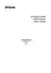
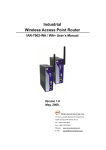
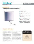
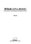
D-Link Air DWL-900AP
Wireless Access Point
Manual
Please see the Quick Install Guide, included separately, for installation instructions.
Building Networks for People
Contents
Contents of Package ..............................................................................3
Introduction .....................................................................................................4
LED Display....................................................................................................5
Connections ...................................................................................................6
Wireless Basics ...........................................................................................7
Network Topology ...................................................................................12
Operation Modes with the DWL-900AP ...............................14
Network Functions of the Access Point ................................16
USB Configuration Utility ..................................................................19
SNMP Management Utility ..............................................................27
Networking Basics ..................................................................................40
Technical Specifications ....................................................................54
D-Link locations ........................................................................................57
Contacting Technical Support ......................................................58
Limited Warranty ......................................................................................59
Registration...................................................................................................62
2
Contents of Package
•
•
•
•
•
•
•
DWL-900AP Wireless Access Point
Installation CD
Quick Install Guide
AC Adapter
USB cable
Power Supply/Cord
User’s Manual
If any of the above items are missing, please contact your reseller.
System requirements:
Computer with USB port
Microsoft Windows XP, 2000, ME, 98, 98SE
3
Introduction
The D-Link Air DWL-900AP 802.11b Wireless Access Point is an ideal way
to extend the reach and number of computers connected to your wireless
network or as part of a wired LAN (Local Area Network) with a wireless
segment.
A Wireless Access Point may be used to serve different functions, including:
•
Bridge - The Wireless Access Point can be used to provide
access to the shared network facilities of an Ethernet LAN.
•
Wireless LAN Extension - The effective communication range of
wireless workstations can be increased.
•
Improve Signal Quality - Providing a central relay station can
provide a communication path for WLAN components that
otherwise might be prevented from “seeing” other WLAN
members.
•
Wireless LAN Security - The Wireless Access Point can be
configured to use encryption for improved security on a WLAN.
After completing the steps outlined in the Quick Install Guide (included
separately) you will have the ability to share information and resources, such
as files and printers, and take full advantage of a “connected” environment
for work and play!
This manual provides a quick introduction to wireless technology and its
application as it relates to networking. Take a moment to read through this
manual and familiarize yourself with wireless technology.
But you should
also give yourself some time to become familiar with your new wireless
network.
4
LED Display
Front Panel
LED Display
Power
LAN
WLAN
On
Blink
Unit is plugged in and
working normally.
Unit is booting up and
running self diagnostic
test
Unit is not plugged in
and it is off
Ethernet cable is
plugged in and there
is a valid network
connection.
The Ethernet port is
active
Ethernet cable not
plugged in or the
connection is not valid
N/A
Detecting Wireless
LAN network activities
No Wireless LAN
network available in
the vicinity
5
Off
Connections
Rear Panel
Connections
Power
5V=1 ~ 2A
Console
Ethernet
Plug in the AC/DC adapter here. Please make sure to plug in adapter to the Wireless
Access Point before plugging the other end of the power adapter to an electrical
wall outlet or power strip.
The USB console port is used to make the USB connection from the device to a
computer with the USB cable for first time configuration and configuration using the
Wireless AP USB Utility.
The Ethernet port is used to connect the Wireless Access Point to the Ethernet LAN or a
single computer using an Ethernet cable (RJ-45).
Note: To use the USB port on the Wireless Access Point, the computer that performs
the configuration must have a USB interface with Windows XP, 2000, 98, or ME
installed. USB is not supported under Windows NT or Windows 95.
Caution: Use only the power adapter included with the
device!
6
Wireless Basics
D-Link Air wireless products are based on industry standards to provide easy
to use and compatible high-speed wireless connectivity within your home or
business. Strictly adhering to IEEE 802.11b, the D-Link Air wireless family of
products will allow you to access the data you want, when and where you
want it. No longer will you be tethered to a workstation or forced to run new
wiring. You will be able to enjoy the freedom that wireless networking
delivers.
A wireless LAN (WLAN) is a cellular computer network that facilitates
communication with radio signals instead of wires. Wireless LANs are used
increasingly in both home and corporate environments. Innovative ways to
utilize WLAN technology are helping people to work and communicate more
efficiently. Increased mobility and the absence of cabling and other fixed
infrastructure has proven to be beneficial for many users.
WLAN users can use the same network applications they use on an Ethernet
LAN. WLAN adapter cards used on laptop and desktop systems, support the
same protocols as Ethernet adapter cards. For most users, there is no
noticeable functional difference between a wired Ethernet desktop computer
or mobile WLAN workstation other than the added benefit of the ability to
roam within the WLAN-cell. Under many circumstances, it may be desirable
for mobile network devices to link to a conventional Ethernet LAN in order
use servers, printers or an Internet connection supplied through the wired
LAN. The Wireless Access Point is a device used to provide this link.
People use wireless LAN technology for many different purposes.
7
Wireless Basics (continued)
Mobility - Productivity increases when people have access to data in any
location within the operating range of the WLAN. Ad-hoc management
decisions based on real-time information can significantly improve worker
efficiency.
Low Implementation Costs - WLANs are easy to set up, manage, change
and relocate. Networks that frequently change, both physically and logically,
can benefit from WLANs ease of implementation. WLANs can operate in
locations where installation of wiring may be impractical. Furthermore, IEEE
standardization mandates interoperability of all WLAN devices that conform
to the 802.11b set of standards.
Installation Speed and Simplicity - Installing a wireless LAN system can be
fast and easy and can eliminate the need to pull cable through walls and
ceilings.
Installation Flexibility - Wireless technology allows the network to go where
wires cannot go.
Reduced Cost-of-Ownership - While the initial investment required for
wireless LAN hardware might be higher than the cost of wired LAN hardware,
overall installation expenses and life-cycle costs will be significantly lower.
Long-term cost benefits are greatest in dynamic environments requiring
frequent moves, adds, and changes.
Scalability - Wireless LAN systems can be configured in a variety of
topologies to meet the needs of specific applications and installations.
Configurations are easily changed and range from peer-to-peer networks
suitable for a small number of users to full infrastructure networks of
thousands of users that allows roaming over a broad area.
8
Wireless Basics (continued)
Our full range of D-Link Air Wireless LAN products include:
Wireless PC cards used with laptop computers
Wireless PCI cards used with desktop computers
Wireless Access Points
Wireless Home Gateways
Standards - Based Technology
The IEEE 802.11b standard designates that devices operate at an optimal
data rate of 11 Megabits per second. This means you will be able to transfer
large files quickly or even watch a movie in MPEG format over your network
without noticeable delays. This technology works by using multiple
frequencies in the 2.4GHz range utilizing Direct Sequence Spread Spectrum
(DSSS) technology. D-Link Air products will automatically sense the best
possible connection speed to ensure the greatest speed and range possible
with the technology.
Features and Standards
Wireless LAN technology is based on the internationally recognized IEEE
802.11 set of standards for wireless LANs. The Wireless Access Point is fully
compliant with the IEEE 802.11b standard and can inter-operate with other
compliant equipment.
The DWL-900AP Wireless Access Point also complies with the following
regulatory standards:
•
FCC part 15 Class A with no external shielding
•
FCC part 15 Class B, ETS 300-339 compliance, including CE mark
•
The regulatory requirements for Japan, Europe and many other areas
of the world
9
Wireless Basics (continued)
The Wireless Access Point features include:
• Data transfer rates of up to 11 Mbps in optimal conditions
• An effective range of up to 900 feet (300 meters) outdoors or 300 feet
(100 meters) indoors
• 10BaseT Ethernet port interface for bridging Wireless LAN to an
Ethernet LAN
• Seamless roaming for notebook computers, wireless PCs, and other
computers equipped with Wireless LAN
• Built-in diagnostics including a power-up self-check
• Dual antenna assembly with optional diversity
• Firmware can be upgraded easily in the field
• Data encryption (WEP 64 and WEP 128)
• SNMP support
• DHCP support (client)
• Optional Short RF preamble
•
USB Configuration
Installation Considerations
Designed to go up to 300 feet (100 meters) indoors and up to 900 feet (300
meters) outdoors, D-Link Air DWL-900AP lets you access your network from
virtually anywhere you want. Keep in mind, however, that the number and
thickness of walls, ceilings or other objects that the wireless signals must
pass thru may limit range. Typical ranges vary depending on the types of
materials and background RF noise in your home or business. The key to
maximizing range is to follow these basic principles:
1. Keep the number of walls and ceilings between the access point and
your receiving device to a minimum - Each wall or ceiling can reduce
your D-Link Air Wireless product’s range from 3-90 feet. For some
10
Wireless Basics (continued)
business of large residential home deployment, it may be more
beneficial to have more than one access point with overlapping
coverage.
2. Be aware of the direct line between Access Points, Residential
Gateways, and Computers - A wall that is 1.5 feet thick, at a 45
degree angle appears to be almost 3 feet thick. At a 2 degree angle it
looks over 42 feet thick! Try to make sure that the AP and Adapters
are positioned so that the signal will travel straight through a wall or
ceiling for better reception.
3. Building Materials make a difference - A solid metal door or aluminum
studs may have a negative effect on range. Again, try to position
Access Points, Residential Gateways, and Computers so that the
signal passes through drywall or open doorways and not other
materials.
4. Make sure that the antenna is positioned for best reception.
5. Keep your product away (at least 3-6 feet) from electrical devices that
generate RF noise, like microwaves, Monitors, electric motors, etc.
For the average residence, range should not be a problem.
If you
experience low or no signal strength in areas of your home that you wish to
access, consider positioning the Access Point in a location directly between
the Residential Gateways and/or Computers that will be connected.
Additional Access Points can be connected to provide better coverage in
rooms where the signal does not appear as strong as desired.
Using radio frequency (RF) technology, WLANs transmit and receive data
over the air, minimizing the need for wired connections. Thus, WLANs
combine data connectivity with user mobility, and, through simplified
configuration, enable movable LANs.
11
Network Topology
The IEEE 802.11b standard supports three basic topologies for WLANs—the
Independent Basic Service Set (IBSS), the Basic Service Set (BSS), and the
Extended Service Set (ESS). Wireless LAN components can be used to
extend, enhance or entirely replace existing Ethernet infrastructure. The
DWL-900AP can accommodate any WLAN topology.
BSS
In a Basic Service Set, a wireless access point performs multiple tasks; it is
a base station and network access controller for the wireless stations in the
BSS. The access point can also provide a connection to a wired Ethernet
LAN for the BSS member stations. An example of a BSS might be a
business meeting conducted in a room with only a single Ethernet port
available. Each participant has a wireless laptop computer and requires
simultaneous access to a data server on the Ethernet LAN. A wireless
access point provides the connection to the Ethernet and acts as the network
control station for the BSS members.
In a BSS, the wireless access point performs functions similar to an Ethernet
switch. The access point controls network access and maintains a
dynamically updated list of all the members of the BSS. Members of each
BSS are added or deleted from the list as they join or leave the BSS.
Wireless stations in the BSS are identified by their MAC (Media Access
Control) address.
IBSS
An Independent Basic Service Set or ad-hoc network consists of two or
more wireless stations that communicate directly, peer-to-peer, without the
services of a wireless access point. An example of an ad-hoc network or
12
Network Topology (continued)I
BSS would be a group of wireless-equipped laptop computers at a trade
show set up to share information. In this arrangement, one of the WLAN units
is elected to act as a controller or base station, similar to the function of a
wireless access point except there is no connection to a wired Ethernet LAN.
Ad-hoc networks are very easy to set up and require minimal involvement by
network administrators or MIS personnel.
ESS
An Extended Service Set is a series of two or more basic service sets
networked on an Ethernet or other type of LAN. Each access point provides
connection to the Ethernet LAN for their respective BSS.
Each BSS is identified by a unique number, the BSS-ID (the MAC address of
the Wireless Access Point). Wireless stations on an ESS automatically select
the access point or BSS that can best serve them. If no access point can be
found the device will scan for a usable access point.
An ESS can be set up so that wireless stations can roam anywhere within
the range of any available access point, that is, to any member BSS, and still
maintain links to both the WLAN and the Ethernet. In this case, each station
shares a common ESS. The ESS is identified by an ESS ID number used by
all stations in the ESS.
Wireless access points can also be used to segment a wireless network.
Under such circumstances, more than one ESS might be used. Two or more
separate Extended Service Sets can occupy the same physical space. Each
station on a wireless LAN can only use one ESS.
13
Operation Modes with the DWL-900AP
Flexibility is fundamental to a wireless network. For this reason, the wireless
access point can be configured to perform different functions and customized
according to the needs of your network.
Access Point
In this mode, the access point provides access for wireless stations to wired
LANs and from wired LANs to wireless stations. Wireless stations within the
range of the access point may communicate with each other via the access
point. This is the default operation mode of the device.
Simple Wireless Access Point
Wireless Bridging
Wireless Bridge mode allows two types of connections:
1. WB Point-to-Point: The wireless bridge is
communicate with a specific remote MAC address.
Wireless Bridge Point-to-Point mode
14
configured
to
Operation Modes with the DWL-900AP (continued)
2. Wireless Bridge Point to Multipoint: The wireless bridge is
configured to communicate with any wireless bridge available on the
same channel and using the same ESS ID.
DWL-900AP
Wireless Bridge Point-to-Multipoint mode
Access Point Client Mode
The access point can also act as a client on a wireless LAN. When
configured as a client the access point functions in the capacity of a wireless
end station only. Communication through the wireless interface of the device
can only be accomplished using another Access Point functioning in AP
mode. When configured as a client, the access point connects to a single
computer or an Ethernet LAN via the Ethernet interface. An access point
configured to be a wireless client connected to a single computer is
illustrated in the figure below.
Wireless Access Point used as a Client
15
Network Functions of the Access Point
The wireless access point performs key network functions controlling access
to both the wireless and Ethernet LANs. The following paragraphs elaborate
on the network function of the wireless access point.
DWL-900AP Bridging
The Wireless Access Point functions as an intelligent bridge. It listens to all
data traffic on all its interfaces and maintains a MAC address database in
much the same way that an Ethernet switch maintains a MAC address table.
MAC address information is updated dynamically and MAC addresses that
are inactive for a specified period are deleted from the database or “aged
out.” The MAC address database also indicates the type of interface being
used by each entry (either WLAN or Ethernet.) Packets destined for unknown
MAC Addresses are forwarded to the Ethernet interface.
When necessary, the Wireless Access Point uses the Address Resolution
Protocol (ARP) to match IP addresses to MAC addresses and stores ARP
information in its database as well. ARP information is likewise aged out of
the database.
Filtering and Access Control
The wireless access point can limit the wireless devices that associate with it
and the data packets that are forwarded through it. Filters can provide a
degree of security and improve network performance by eliminating
broadcast/multicast packets from the radio network.
The ACL (Access Control List) contains the MAC address of every wireless
device allowed to associate with the access point. This prevents
unauthorized access to network resources.
The access point can discriminate based on the destination address of
packets it handles by maintaining a list of disallowed destinations. This can
improve efficiency by eliminating unnecessary transmission of data packets.
The type of packet forwarded through the access point can be controlled
using a filter. Type Filtering prevents specific packets from being processed.
Certain packet types such as broadcast packets from devices not important
to the wireless LAN are discarded to preserve bandwidth. Filtering out
unnecessary frames can improve overall network performance.
16
Network Functions of the Access Point (continued)
DHCP Support
The access point supports the Dynamic Host Configuration Protocol (DHCP)
used to obtain a leased IP address and network configuration information
from a remote server. When DHCP is enabled, the access point sends out a
DHCP request to obtain the IP settings and network configuration information.
The access point can be configured to download two additional files when a
boot takes place, the firmware file and an HTML file. DHCP or BOOTP
servers can be programmed to transfer these two files when a DHCP request
is made.
Media Types
The wireless access point can be used to bridge the wired Ethernet LAN and
wireless LAN radio network. The 10BASE-T Ethernet interface fully complies
with Ethernet Rev. 2 and IEEE 802.3 specifications and operates in full
duplex. The radio interface conforms to IEEE 802.11b specifications for
wireless LAN. The WLAN interface operates at speeds of up to 11 Mbps
using direct sequence radio technology. The wireless access point supports
multiple-cell operations with fast roaming between cells. With the direct
sequence system, each cell operates independently. Adding cells to the
network can increase the coverage area and total system capacity. The
access point supports wireless devices operating in Continuously Aware or
Power Save modes.
Media Access Control
All WLAN devices, like all Ethernet devices, have a unique, hardwareencoded Media Access Control (MAC) address. Wireless LAN algorithms
employ carrier sense and collision avoidance techniques (CSMA/CA) to
ensure network access to all devices and error checking (CRC) for accuracy
of data transmissions. The method of access control used in WLAN is called
the Distributed Coordination Function (DCF).
17
Network Functions of the Access Point (continued)
Data Transfer Rates
The actual rate at which data transmission occurs varies according to the
strength of the signal transmitting the data. Distance and environment can
effect the strength of the signal that can be transmitted and received. The
signal strength determines the type of modulation technique used to encode
data, which effects the volume of data (i.e. the number of bits) that can be
encoded in a given space of the carrier signal. The IEEE 802.11b standard
specifies that WLAN devices adapt the rate of transmission to use the best
rate achievable. Each wireless device first determines if conditions diminish
signal strength and then chooses one of four possible bit rates (1, 2, 5.5, or
11 Mbps) based on this learned information.
18
USB Configuration Utility
When the Wireless AP USB Configuration Utility and Wireless AP SNMP
(Simple Network Management Protocol) Utility have been installed you can
configure settings for the access point. Before you can use the SNMP Utility,
you must configure the device IP address. The IP address of the device must
be on the same subnet and use the same subnet mask as the computer
using the SNMP Utility.
Using the USB Configuration Utility
To use the USB Configuration Utility and change the IP settings of the
Access Point, follow these steps:
1. To launch the USB Configuration Utility, go to your Start menu, open
Programs, find the Wireless AP folder and open it. You will see two new
icons have been placed in this folder. Scroll to the Wireless AP USB
Utility and click on it to launch the program.
2. The Admin Password screen will ask you for a password. The default
password is “public” (all lower case), type this in the space and click OK.
3. The USB Configuration Utility management interface will appear
displaying system information about the Wireless Access Point. To
access any of the menus listed just click on the tab. If you intend to use
the SNMP Utility to manage and configure the device you must first
change the IP settings.
19
4. Click the IP Config tab to change the IP settings of the device.
USB Configuration Utility (continued)
Note: Once you have assigned or obtained an IP Address for the DWL900AP, through the USB Configuration Utility, we recommend that you
manage your network using the SNMP Utility (please refer to the chapter
in this manual entitled “SNMP Management Utility”.) If you choose to
manage your network using the USB Utility, you will need to connect the
DWL-900AP to a computer on your network, using the USB cable, each
time you have a management session on your network.
5. Change the IP settings of the access point. You may elect to use a
DHCP server to determine the IP settings, or set them according to
the requirements of your IP addressing scheme.
To configure the device as a DHCP client, select Enable from the DHCP
Client: pull-down menu.
20
To manually assign the IP settings, you must Disable the DHCP client
function and set the IP address and subnet mask. If necessary, you can
assign a Gateway IP address for the device here as well.
USB Configuration Utility (continued)
Finally, if you are using DHCP to assign IP settings, you must select the
port used for communication with the DHCP server. Change the Primary
Port: setting to Ethernet (set by default) or Wireless, according to how
the device will receive DHCP information.
Note: Now that you have obtained an IP Address for your DWL-900AP,
we recommend that you skip ahead to the “SNMP Management Utility”
Chapter in this manual to learn how to manage your network without
using the USB cable.
21
USB Utility Menus
If you elect to use the USB Configuration Utility to manage your network, you
will need to connect your computer, using the USB cable, to the DWL-900AP
each time you have a management session. (Skip ahead to the SNMP
Management Utility section to learn about USB cable-free management of
your network.)
Wireless Setting
Use the Wireless Operation menu to set parameters that enable the Access
Point to communicate with other stations on the wireless LAN.
Define these Wireless parameters:
Access Point Name: The Access Point can be assigned a name for easy
reference here.
Wireless ESSID: The ESSID is used by all wireless devices within the ESS
or extended wireless LAN. This can be any alpha-numeric value up to 32
22
USB Utility Menus (continued)
units long. Use this to prevent cross communication between two or more
WLANs in one area.
Operational Rate Set: By default, the unit adaptively selects the highest
possible rate for transmission. Select the basic rates to be used among the
following options: Auto, 1, 2, 5.5, or 11 Mbps. For most networks the default
setting, Auto will be the best choice. When Auto (Rate Fall Back) is enabled
the transmission rate will select the optimum rate. If obstacles or interference
are present, the system will automatically fall back to a lower rate.
Wireless Channel: There are 14 channels available for with the Access
Point. All devices communicating with the device must use the same channel.
There may be restrictions on which channel can be used in some countries.
In Canada and the US, channels 1 - 11 are authorized for use by the IC and
the FCC.
Operation Mode
Use this menu to select how the Access Point will function on your WLAN.
The previous discussion of Operations Modes contains illustrated examples
of the four available operation modes. Click Apply to put the changes into
effect.
Choose one of the following from the Operation Mode pull-down menu:
Access Point
This mode provides access for wireless stations to a wired Ethernet LAN and
from the wired LAN to the wireless stations. Furthermore, wireless stations
within the range of the Access Point will communicate with each other
through the device. This is the default operation mode of the Access Point.
Access Point Client
This mode can be used to connect a remote Ethernet LAN or a single station
with a central LAN, to create an extended single virtual LAN. In this way, any
station of the Remote LAN can successfully communicate with any station of
the central LAN as if they were members of the same physical LAN. Wireless
end stations can not associate with an Access Point in Client mode except by
means of another access point. As a client, the Access Point must operate
within a BSS and therefore must use a designated BSS base station (usually
another Access Point) for all communications through its wireless interface.
Use the Preferred BSSID: entry field to define the wireless station used to
direct wireless traffic of the device.
23
USB Utility Menus (continued)
Wireless Bridge- Two types of wireless bridge connections are allowed:
1. Point-to-Point- The Access Point still functions as the central controller
for wireless stations within its BSS, but it will communicate with only one
other wireless bridge. The designated access point with which it
communicates is identified by the Preferred BSSID.
2. Point to Multipoint- The Access Point is able to communicate with any
available wireless bridge on the same channel.
Advanced Wireless Operation
Click the Advanced button to define the parameters described below. A new
window will appear. Define the following parameters:
Fragment Threshold:
Fragment Threshold defines a threshold above which the wireless packetwill
be split up, or fragmented. For a fragmented packet, if transmission of part of
it were to be interfered with, only the portion that was successfully
transmitted would need to be re-sent. Throughput will generally be lower for
fragmented packets, since the fixed packet overhead consumes a higher
portion of the RF bandwidth.
RTS Threshold:
The RTS Threshold sets an upper threshold at which point the device will
issue an RTS packet. The RTS (Request To Send) packet is used for the
purpose of avoiding data collisions on the wireless LAN. There are several
trade offs to consider when setting this parameter. Setting this parameter to a
24
USB Utility Menus (continued)
small value causes RTS packets to be sent more often, consuming more of
the available bandwidth, therefore reducing the apparent throughput of other
network packets. However, the more often RTS packets are sent, the quicker
the system can recover from interference or collisions. Refer to the IEEE
802.11 Standard for more information on the RTS/CTS mechanism.
Beacon Period: The Beacon Period specifies the duration between beacon
packets in milliseconds. The range for the beacon period is between the
ranges of 20 to 1000 with a typical value of 100.
Encryption
If an additional measure of security is desired on the wireless network, WEP
(Wired Equivalent Privacy) encryption can be enabled. WEP encrypts each
frame transmitted from the wireless adapter using one of the keys entered in
the WEP Privacy field. The Access Point or wireless adapter will accept only
encrypted frames that it can decrypt correctly. Decrypting can take place only
if the receiver has the correct key used by the transmitter.
25
USB Utility Menus (continued)
WEP Type: The 64 or 128-bit Wired Equivalent Privacy Algorithm. Use this
enable 64-bit or 128-bit encryption. WEP is disabled by default.
Active Key: Active Key ID determines which Key (Key 1 to Key 4) encrypts
and decrypts the transmissions received by the Access Point.
Authentication Type: Choose Open System, Shared Key or Both.
Open System: With this setting any station in the Wireless LAN can
associate with an Access Point to receive and to transmit data.
Shared Key: With this setting only stations using a shared key encryption
identified by the Access Point are allowed to associate with it.
Both: With this setting stations can communicate with or without data
encryption.
Key 1 - Key 4
64 bit: Active Key ID 1 to 4. These values can only be edited if a WEP
type is selected to 64-bits.
128 bit: Active Key ID 1 to 4. These values can only be edited if a WEP
type is selected to 128-bits.
These four fields can be used to manually enter the encryption keys. This
may be necessary if you wish this node to match keys in a different vendor's
product. These fields also display the keys when they are generated using a
Pass-phrase.
NOTE: 64 bit WEP is the same as 40 bit WEP! The lower level of WEP
encryption uses a 40 bit (10 character) “secret key” (set by the user), and a
24 bit “Initialization Vector” (not under user control). The panel allows the
entry of four keys for 64-bit encryption and one set for 128-bit key encryption.
Each key must consist of hex digits, which means that only digits 0-9 and
letters A-F are valid entries. The Configuration Utility will not apply keys that
are not entered correctly.
Click Apply to set Encryption code settings.
26
SNMP Management Utility
SNMP (Simple Network Management Protocol) is a network monitoring and
control protocol. Once you have installed the Wireless Access Point SNMP
Utility and assigned an IP Address through the USB Configuration Utility
(see the Quick Install Guide,) you can configure the remaining settings to suit
the needs of your network. The USB Configuration Utility contains the
same menu options as the SNMP Utility, however, you will need to connect
your computer to the DWL-900AP via USB cable each time you manage your
network with the USB Configuration Utility. Using the SNMP Management
Utility, you can configure your network on any networked computer without
using the USB connection. The settings menus are described in this section.
Accessing the SNMP Manager
Follow these steps to access the Wireless Access Point manager from the
manager PC:
From the Start menu, Start > Programs > Wireless AP >
Wireless AP SNMP Utility
A new screen, the Wireless Access Point Searching Utility, will appear. If
the device does not appear listed in the screen, click the Search button. The
Search button is the magnifying glass icon.
Click the
Search button
to locate the
device
27
SNMP Management Utility (continued)
Double click on the device in the list you wish to configure. You will be
prompted for a password in a new screen, the Admin. Authorization
Password window. Type in the default password “public” and click OK.
The Wireless Access Point Configuration Utility menu will appear
displaying the System tab.
You may now use any of the management functions available in the SNMP
Configuration Utility.
28
SNMP Utility Menus (continued)
Click on the appropriate tab to access any menu in the Wireless Access
Point SNMP Configuration Utility.
System
The System menu will appear whenever the SNMP Configuration Utility is
first accessed or you can click on the System tab at any time to view the
menu. The System menu lists the following:
System Reset
Clicking the System Reset button will reset the device and initiate any
changes that have been made to the device configuration settings.
Configuration settings are saved to Non-volatile RAM (NV-RAM). This should
be the last thing you do when you are ready to exit the Configuration Utility.
29
SNMP Utility Menus (continued)
Load Default
Clicking this button will load the factory default configuration settings into the
NV-RAM of the device.
Device Information
Device information includes basic information about the Access Point
including the name of the device, the firmware version currently being used,
the MAC address and the regulation domain in which it resides.
Trap Enable
Use this to Enable or Disable SNMP traps.
User Authorized Setting
Use this to create user accounts identified by unique user names and
passwords that allow read-only access to the SNMP Utility.
Admin Authorized Setting
Use this to create administrator accounts for administrator access to the
SNMP Utility. Administrator privileges allow full read-write access to the
SNMP Utility.
30
SNMP Utility Menus (continued)
IP Config
Use this menu to view, set or change IP settings. You can set them manually
or allow a DHCP server to assign IP settings.
Listed in the Bridging Level information field are the following:
MAC Address
A unique 48-bit, hard-coded Media Access Control address used to identify
devices on the WLAN and Ethernet LAN.
IP Settings
You may change any of the IP settings by simply typing in the desired
address or net mask. Click Apply to put the changes into effect. Remember
that if you change the IP address of the device to an address that is outside
the subnet of the computer you are using, you will lose access to the SNMP
Utility.
31
SNMP Utility Menus (continued)
IP Address
The Internet Protocol address of the Access Point
Subnet mask
Four sets of three digits used to logically divide an IP network into subnetworks.
Gateway
The IP address of a gateway device necessary for communication with
devices outside the subnet of the Access Point. If your network is not divided
into different subnets, this can remain blank.
DHCP
The Access Point can be configured as a DHCP client by choosing Enabled
in the DHCP enable pull-down menu. By default DHCP support is Disabled.
If the Access Point is configured as a DHCP client, it will be necessary to
decide what media will be used to transport DHCP information to the device.
By default the Access Point is configured to receive IP settings through the
Ethernet port. If your network is set up so that DHCP services are supplied
through the wireless LAN, you must change the Primary port: setting to
Wireless in the pull-down menu and click Apply to put the change into effect.
Click Refresh to refresh the screen to list the most current settings.
32
SNMP Utility Menus (continued)
Statistics
Various statistics concerning both Ethernet and wireless operation of the
Access Point can be viewed in the Statistics window. This window can be
useful for monitoring performance and diagnosing problems associated with
the device or its BSS.
33
SNMP Utility Menus (continued)
Wireless Operation
Use the Wireless Operation menu to set parameters that enable the Access
Point to communicate with other stations on the wireless LAN.
Define these Wireless parameters:
Channel ID:
There are 14 channels available with the Access Point. All devices that
communicate must use the same channel. There may be restrictions on
which channel can be used in some countries. In Canada and the U.S.,
channels 1 - 11 are authorized for use by the IC and the FCC.
ESSID:
The ESSID is used by all wireless devices within the ESS or extended
wireless LAN. This can be any alpha-numeric value of up to 32 units long.
Use this to prevent cross communication between two or more WLANs in
one area.
34
SNMP Utility Menus (continued)
Access Point Name:
The Access Point can be assigned a name for easy reference here.
Transmit Rate:
By default the unit adaptively selects the highest possible rate for
transmission. Select the basic rates to be used among the following options:
Auto, 1, 2, 5.5, or 11 Mbps. For most networks the default setting, Auto will
be the best choice. When Auto (Rate Fall Back) is enabled the transmission
rate will select the optimum rate. If obstacles or interference are present, the
system will automatically fall back to a lower rate.
Operation Mode
Use this menu to select how the Access Point will function on your WLAN.
The previous discussion of Operations Modes contains illustrated examples
of the four available operation modes. Click Apply to put the changes into
effect.
Mode: Choose one of the following:
Access Point:
This mode provides access for wireless stations to a wired Ethernet LAN and
from the wired LAN to the wireless stations. Furthermore, wireless stations
within the range of the Access Point will communicate with each other
through the device. This is the default operation mode of the Access Point.
Access Point Client:
This mode can be used to connect a remote Ethernet LAN or a single station
with a central LAN, to create an extended single virtual LAN. In this way, any
station of the Remote LAN can successfully communicate with any station of
the central LAN as if they were members of the same physical LAN. Wireless
end stations can not associate with an Access Point in Client mode except by
means of another access point. As a client, the Access Point must operate
within a BSS and therefore must use a designated BSS base station (usually
another Access Point) for all communications through its wireless interface.
Use the BSSID: entry field to define the wireless station used to direct
wireless traffic of the device.
Wireless Bridge: Two types of wireless bridge connections are allowed:
3. Point-to-Point: The Access Point still functions as the central controller
for wireless stations within its BSS, but it will only communicate with one
other wireless bridge. The designated access point with which it
communicates is identified by the BSSID.
4. Point to Multipoint: The Access Point is able to communicate with any
available wireless bridge on the same channel.
35
SNMP Utility Menus (continued)
Advanced Wireless Operation
Click the Advanced button to define the parameters described below.
A new window will appear.
In the Threshold field define the following parameters:
RTS:
The RTS Threshold sets an upper threshold at which point the device will
issue an RTS packet. The RTS (Request To Send) packet is used for the
purpose of avoiding data collisions on the wireless LAN. There are several
trade-offs to consider when setting this parameter. Setting this parameter to
a small value causes RTS packets to be sent more often, consuming more of
the available bandwidth, therefore reducing the apparent throughput of other
network packets. However, the more often RTS packets are sent, the quicker
the system can recover from interference or collisions. Refer to the IEEE
802.11 Standard for more information on the RTS/CTS mechanism.
36
SNMP Utility Menus (continued)
Fragment Threshold:
Fragment Threshold defines a threshold above which the wireless packet
will be split up, or fragmented. For a fragmented packet, if transmission of
part of it were to be interfered with, only the portion that was successfully
transmitted would need to be re-sent. Throughput will generally be lower for
fragmented packets, since the fixed packet overhead consumes a higher
portion of the RF bandwidth.
Preamble Type:
Preamble is the first sub-field of PPDU, which is the appropriate frame format
for transmission to PHY (Physical layer). There are two options, Short
Preamble and Long Preamble. The Short Preamble option improves
throughput performance.
Authorized MAC Address
For security purposes the Access Point can discriminate its associations with
other wireless stations. The Authorized MAC Address lets you select which
stations are allowed throughput on the wireless interface. First you must
enable the MAC address authorization table by placing a checkmark in the
Enable Auth. Table box. When you want to leave this menu click OK to use
the table. The table is maintained manually and can be updated and edited
by downloading MAC addresses to the data table. This is described below.
You can supply a list of authorized MAC addresses to the Access Point.
Perform the following tasks:
1. Click the Load file button and enter the file name and location of the file
you want to load. The file should contain the MAC addresses you wish to
add to the table of authorized addresses. The file should be a simple text
document with each MAC address written on a separate line.
2. Once the file has been loaded, click the Download button to download
the Authorized MAC Address file to the Access Point.
Click on Get to obtain a list of the Authorized MAC Addresses currently
entered on the table.
37
SNMP Utility Menus (continued)
Encryption
If an additional measure of security is desired on the wireless network, WEP
(Wired Equivalent Privacy) encryption can be enabled. WEP encrypts each
frame transmitted from the wireless adapter using one of the keys entered in
the WEP Privacy field. The Access Point or wireless adapter will accept only
encrypted frames that it can decrypt correctly. Decrypting can take place only
if the receiver has the correct key used by the transmitter.
Active Key: Active Key ID determines which Key (Key 1 to Key 4) encrypts
and decrypts the transmissions received by the Access Point.
WEP Type: The 64 or 128-bit Wired Equivalent Privacy Algorithm. Use this
to enable 64-bit or 128-bit encryption. WEP is disabled by default.
Authentication Type: Choose Open System, Shared Key or Both.
Open System: With this setting any station in the Wireless LAN can
associate with an Access Point to receive and to transmit data.
38
SNMP Utility Menus (continued)
Shared Key: With this setting only stations using a shared key
encryption identified by the Access Point are allowed to associate with it.
Both: With this setting stations can communicate with or without data
encryption.
Key 1 - Key 4
64 bit: Active Key ID 1 to 4. These values can only be edited if a WEP type
is selected to 64-bits.
128 bit: Active Key ID 1 to 4. These values can only be edited if a WEP type
is selected to 128-bits.
These four fields can be used to manually enter the encryption keys. This
may be necessary if you wish this node to match keys in a different vendor's
product. These fields also display the keys when they are generated using a
Pass-phrase.
NOTE: 64 bit WEP is the same as 40 bit WEP! The lower level of WEP
encryption uses a 40 bit (10 character) “secret key” (set by the user), and a
24 bit “Initialization Vector” (not under user control). The panel allows the
entry of four keys for 64-bit encryption and one set for 128-bit key encryption.
Each key must consist of hex digits, which means that only digits 0-9 and
letters A-F are valid entries. The Configuration Utility will not apply keys
that are not entered correctly.
About
The About tab displays general
information about the SNMP Manager.
This screen also displays the software
version of SNMP Manager and the
firmware version of the Wireless Access
Point.
39
Networking Basics
You may have had some ideas about how to use your new network prior to
installing this product - sharing files, printing from a computer on the network,
or accessing the Internet on multiple computers with one connection. This
section will help you get started on those ideas or even give you some new
ones. However, this section is not intended to be a comprehensive guide to
networking, it is just an outline of a few networking basics. If you are
interested in learning more about networking please visit our website:
D-Link Systems, Inc. http://www.dlink.com
D-Link is one of the largest manufacturers of Ethernet products in the world.
D-Link’s technological expertise and dedication to providing quality products
at a low price makes D-Link a good place to watch for the newest in
networking innovations. Or, you can get the newest drivers available for your
Network Adapters.
40
Networking Basics
Computer Identification
If you had previously given your Windows 98 computers names or if you are
using Windows 98, you may need to verify that each computer has a unique
name and common workgroup name.
A. On your Desktop, right-click the icon Network Places and select
Properties from the context menu.
B. Click the Identification tab on the top of the dialog box.
41
Networking Basics
Computer Identification (continued)
C. Type a unique, identifying name for this particular computer
in the Computer name field. This will be the name that other computers
on your network will use to communicate with this computer. Each
computer’s name must be unique on a particular network or confusion will
result. (The computer’s name should be 15 or fewer characters with no
spaces.)
D. Type the workgroup name this computer will be a part of in
the Workgroup field. All of the computers on your network should have
an identical Workgroup name.
E. The Computer Description field is optional. You may enter
a description that will help you identify this computer on your network.
Then click Close.
F. Repeat this process for each computer on your network to
ensure that they all have a unique Computer Name and identical
Workgroup.
42
Networking Basics
Sharing Files
With your computers connected together on a network, you may now open
and save files on another computer. You will be able to specify particular
folders or disk drives to "share" and even password protect them. The steps
below will enable you to share specific files and folders with other computers
on your network.
A. On your Desktop, right-click the icon Network Places and select
Properties from the context menu.
B. This dialog box is where you will come to configure most of your
computer network settings. It is also available through the Network icon
in the Control Panel.
C. Click the File and Print Sharing button.
43
Networking Basics
Sharing Files (continued)
D. Click to place a check mark next to "I want to be able to give others
access to my files."
E. Click OK on the File and Print Sharing dialog box.
F. Click OK on the Network dialog box.
G. Provide the Windows 98 installation CD or diskette(s) if prompted or direct
Windows to the proper location of the installation files. Reboot if prompted.
H. You will now be able to identify a particular folder or disk drive to share.
You may want to share a folder that both you and a colleague/family
member need to access occasionally. Or, maybe you want to share a CDROM drive so your other computer that does not have one can read CD’s.
Both processes are the same. Only the disk drives and folders that you
specifically identify as shared will be accessible to other computers on your
network.
44
Networking Basics
Sharing Files (continued)
I. Find the disk drive or folder you want to share using
Windows Explorer or the My Computer icon on your desktop.
J. Right-click on the disk drive or folder icon and select Sharing.
45
Networking Basics
Sharing Files (continued)
K. Select Shared As to set the parameters for sharing this
particular disk drive or folder.
L. The Share Name field is used to identify the disk drive or
folder you are sharing to other computers on the network.
You can give it any name you wish. However, a specific
identification may help as more resources on your network
are shared.
M. The Comment field is optional. You can use this to
further describe the disk drive or folder for others on the network.
N. Access Type allows you to designate how much access
others on the network can have with this disk drive or folder. Read-Only
allows others only to look at or open the files on the disk drive or in the
folder. Full allows others to read, write, open, save, copy, move, and
delete files on the disk or in the folder. Depends on Password gives
other computers access conditional upon the password they provide.
46
Networking Basics
Sharing Files (continued)
O. Passwords allow you to apply a level of security to your
shared disk drives and folders. Another computer (user) will be required
to enter the password you designate here before accessing the disk drive
or folder. Two passwords are used to give two levels of security (or
access) to others on the network using the Depends on Password
setting. Leaving the Password fields blank gives everyone on the
network access to the disk drive or folder.
P. Click OK to continue. You will be prompted to enter the
password(s) you provided for verification. Retype the
password(s) just as you entered them the first time.
Q. You may now access this disk drive or folder from another
computer on your network. Do so by double-clicking the My Network
Places icon on your desktop or inside Windows Explorer.
R. Navigate to the computer with the shared disk drive or
folder (recognized by the Computer Name you provided), double-click.
You should now see the disk drive or folder, double-click. If you specified
a password when sharing this disk drive or folder, you will be prompted
for the password.
S. You can access a disk drive or folder shared over the
network from most Windows applications. To make this process easier,
Windows allows you to map these disk drives and folders to a drive letter
on another computer. For example, on a computer where you are
accessing a shared folder from another computer, inside Windows
Explorer right-click and select Map Network Drive. You will then be able
to assign an available drive letter. Checking Reconnect at logon allows
Windows to map this network drive each time you start your computer.
47
Networking Basics
Sharing Printers
Sharing a printer connected to one computer with other computers on your
network can be very convenient - allowing you to print from any computer on
the network. The steps below will enable you to print with other computers
on your network.
A. On your Desktop, right-click the icon Network Places and select
Properties from the context menu.
48
Networking Basics
Sharing Printers (continued)
B. Click the File and Print Sharing button.
C. Click to place a check mark next to "I want to be able to allow others to
print to my printer(s)."
D. Click OK on the File and Print Sharing dialog box.
E. Click OK on the Network dialog box.
F. You may now share any installed printers connected to
this computer with other computers on your network.
49
Networking Basics
Sharing Printers (continued)
Go to START>SETTINGS>PRINTERS
Right click on the printer you want to share with others on the network and
select Sharing.
G. Click Share As and provide a Share Name to identify
the printer to other computers on the network. Comment
and Password are optional. Then click OK.
For a computer to access a Network Printer, the device driver or software
for that printer must be installed and pointed to the proper location of the
printer. This is done much the same way you installed the printer on the
computer it is connected to.
H. Go to a computer that does not have the printer connected
to it. From the Start button on the Task Bar select Settings and then
Printers.
I.
Double click the Add Printer icon.
J. The Add Printer Wizard will appear. Click Next.
K. Choose Network printer and click Next.
50
Networking Basics
Sharing Printers (continued)
L. Now you will identify the location of the Network Printer.
If you know the name of the computer and the share name of the printer,
you can type it into the Network path or queue name box. However, it is
easier to click the Browse button and navigate to the location of the printer.
Click OK when you have selected the desired printer. Finish the
installation by continuing the Add Printer Wizard normally.
M. You may now use the Network Printer as if it was connected
directly. Note: the computer that the printer is connected to must be “on”
to use the printer. If you find this inconvenient, devices known as
Network Print Servers are available from D-Link including the DP-301
and DP-101P+. A Network Print Server would allow you to directly
connect your printer to your network without worrying about which
computer is “on.”
51
Networking Basics
Checking the Connection by Pinging
Go to START > RUN
Type command in the Open field.
Click OK to get to a DOS prompt.
52
Networking Basics
Checking the Connection by Pinging (continued)
For example, you can type "ping 192.168.0.10," if that is the IP address of
the DWL-900AP in this case, and hit the "Enter" key.
A successful ping will show four replies. The IP Address shown is only an
example, your IP Address may be different.
Type Exit at the prompt to close the screen.
53
Technical Specifications
Standards
• IEEE 802.11b
• IEEE 802.3 10Base-T Ethernet
Ports
• (1) RJ-45, 10Base-T Ethernet port
• (1) USB 1.1, Type B
Network Protocols:
• TCP/IP
• IPX/SPX
• NetBEUI
• ARP
• SNMP
• DHCP
• NDIS3
• NDIS4
Data Security:
• 64-bit, 128-bit WEP (Wired Equivalent Privacy) Encryption
Data Rate and Modulation
• 11Mbps - CCK
• 5.5Mbps - CCK
• 2Mbps - DQPSK
• 1Mbps – DBSK
Power Input
• DC 5V, 1A ~ 2A
• Use External Power Supply
Antenna:
• One External 2.5dB gain antenna w/ reverse SMA connector
54
Transmit Power
• +12.5dBm typical
• Up to 900ft outdoors or 300ft indoors
Reception Sensitivity
Nominal Temp Range
- 1Mbps 10-5 BER @ -89 dBm, Minimum
- 5.5Mbps 10-5 BER @ -83 dBm, Minimum
-11Mbps 10-5 BER @ -79 dBm, Minimum
Frequency Range:
• 2.4 – 2.497 GHz ISM band
• 11 Channels
Modulation:
• Direct Sequence Spread Spectrum (DSSS)
Operating Modes
• Access Point
• Wireless Bridge
- Point to Point
- Point to Multipoint
• Client AP
Roaming
• Among Access Points on the same subnet
Management
• SNMP Manager to manage wireless LAN, network connection and
client access control
• USB Configuration
• TFTP Client for firmware upgrade
• Set IP Session (ARP/ping)
• DCHP client
Diagnostic LEDs:
• Power (Green): Power Indicator
• Link (Green): Ethernet Link Indicator
• WLAN (Green): Wireless Link Indicator
55
Temperature:
• Operating Temperature: 32°F to 131°F
• Storing Temperature: -4°F to 140°F
Humidity:
• Max. 95%, non-condensing
Emissions:
• FCC
• CE
Safety:
• UL
• TUV
Warranty:
• One-Year Limited Warranty
56
D-Link locations
D-Link Australia
Unit 16, 390 Eastern Valley Way
Roseville, NSW 2069,
Australia
TEL: 61-2-94177100
FAX: 61-2-94171077
URL: www.dlink.com.au
D-Link Germany
Schwalbacher Strasse 74
D-65760 Eschborn
Germany
TEL: 49-6196-77990
FAX: 49-6196-7799300
URL: www.dlink.de
D-Link Benelux
Fellenoord 1305611 ZB
EindhovenThe Netherlands
TEL: 31-40-2668713
FAX: 31-40-2668666
URL: www.dlink-benelux.nl/
D-Link India
Plot No.5, Kurla-Bandra Complex Rd.
Off Cst Rd. Santacruz (E), Bombay - 400 098
India
TEL: 91-22-652-6696
FAX: 91-22-652-8914
URL: www.dlink-india.com
D-Link Canada
#2180 Winston Park Drive
Oakville, Ontario, L6H 5W1
Canada
TEL: 1-905-8295033
FAX: 1-905-8295095
URL: www.dlink.ca
D-Link China
2/F., Sigma Building, 49 Zhichun Road,
Haidian District, 100080 Beijing,
China
TEL: 86-10-88097777
FAX: 86-10-88096789
D-Link South America
Isidora Goyeechea 2934 of 702,
Las Condes
Santiago ¡V Chile S.A.
TEL: 56-2-232-3185
FAX: 56-2-232-0923
URL: www.dlink.cl
D-Link Italia
via Nino Bonnet n. 6/b
20154 ¡V Milano,
Italy
TEL: 39-02-2900-0676
FAX: 39-02-2900-1723
URL: www.dlink.it
D-Link Japan
10F, 8-8-15 Nishi-Gotanda
Shinagawa-ku, Tokyo 141,
Japan
TEL: 81-3-5434-9678
FAX: 81-3-5434-9868
URL: www.d-link.co.jp
D-Link Norway
Waldemar Thranesgt. 77,
0175 OsloNorway
TEL: 47-22-991890
FAX: 47-22-207039
D-Link Denmark
Naverland 2, DK-2600
Glostrup, Copenhagen,
Denmark
TEL: 45-43-969040
FAX: 45-43-424347
URL:www.dlink.dk
D-Link Russia
Michurinski Prospekt 49,
117607 Moscow,
Russia
TEL: 7-095-737-3389, 7-095-737-3492
FAX: 7-095-737-3390
D-Link Middle East
7 Assem Ebn Sabet Street Heliopolis Cairo
Egypt
TEL: 20-2-6356176
FAX: 20-2-6356192
URL: www.dlink-me.com
D-Link International (Singapore)
1 International Bussiness Park
#03-12 The Synergy
Singapore 609917
TEL: 65-774-6233
FAX: 65-774-6322
URL: www.dlink-intl.com
D-Link Finland
Thlli-ja Pakkahuone Katajanokanlaituri 5
FIN-00160 Helsinki
Finland
TEL: 358-9-622-91660
FAX: 358-9-622-91661
URL: www.dlink-fi.com
D-Link France
Le Florilege #.2, Allee de la Fresnerie
78330 Fontenay le Fleury
France
TEL: 33-1-30238688
FAX: 33-1-30238689
URL: www.dlink-france.fr
D-Link South Africa
102 - 106 Witchhazel Avenue
Einstein Park 2
Block B
Highveld Technopark
Centurion
South Africa
TEL: 27(0)126652165
FAX: 27(0)126652186
D-Link Spain
Gran Via de Carlos III,
843¢X Edificio Trade08028 BARCELONA
TEL: 34 93 4965751
FAX: 34 93 4965701
URL: www.dlinkiberia.es
57
D-Link Sweden
P.O. Box 15036, S-167 15 Bromma
Sweden
TEL: 46-(0)8564-61900
FAX: 46-(0)8564-61901
URL: www.dlink.se
D-Link Taiwan
2F, No. 119 Pao-Chung Rd.
Hsin-Tien, Taipei
Taiwan
TEL: 886-2-2910-2626
FAX: 886-2-2910-1515
URL: www.dlinktw.com.tw
D-Link U.K.(Europe)
4th Floor, Merit House
Edgware Road, Colindale
London NW9 5AB
U.K.
TEL: 44-20-8731-5555
FAX: 44-20-8731-5511
BBS: 44-181-235-5511
URL: www.dlink.co.uk
D-Link U.S.A
53 Discovery Drive
Irvine, CA 92618
U.S.A.
TEL: 1-949-788-0805
FAX: 1-949-753-7033
URL: www.dlink.com
Contacting Technical Support
You can find the most recent software and user documentation on the D-Link
website.
D-Link provides free technical support for customers within the United States
for the duration of the warranty period on this product.
U.S. customers can contact D-Link technical support through our web site,
by e-mail, or by phone.
United States technical support is available Monday through Friday from 6:00
a.m. to 6:00 p.m. (PST).
Web:
http://www.support.dlink.com
Email:
[email protected]
Phone:
949-790-5290
If you are a customer residing outside of the United States, please refer to
the list of D-Link locations that is included in this manual.
Thank you for purchasing this product.
We like to receive feedback from our customers concerning our products.
Please take a moment to visit our web site. You can register your purchase
on-line, learn more about the newest networking products, and let us know
the things your new network has empowered you to do.
58
Limited Warranty
D-Link Systems, Inc. (“D-Link”) provides this limited warranty for its product only to the person
or entity who originally purchased the product from;
•
•
D-Link or its authorized reseller or distributor.
Products purchased and delivered with the fifty United States, the District of
Columbia, US Possessions or Protectorates, US Military Installations, addresses
with an APO or FPO.
Limited Hardware Warranty: D-Link warrants that the hardware portion of the D-Link
products described below (“Hardware”) will be free from material defects in workmanship and
materials from the date of original retail purchase of the Hardware, for the period set forth
below applicable to the product type (“Warranty Period”) if the Hardware is used and serviced
in accordance with applicable documentation; provided that a completed Registration Card is
returned to an Authorized D-Link Service Office within ninety (90) days after the date of
original retail purchase of the Hardware. If a completed Registration Card is not received by an
authorized D-Link Service Office within such ninety (90) day period, then the Warranty Period
shall be ninety (90) days from the date of purchase.
Product Type Warranty Period
•
Product (excluding power supplies and fans) One (1) Year from the date purchased.
(For service or repair – proof of purchase will be required.)
•
Power Supplies and Fans One (1) Year.
•
Spare parts and spare kits Ninety (90) days.
D-Link’s sole obligation shall be to repair or replace the defective Hardware at no charge to
the original owner. Such repair or replacement will be rendered by D-Link at an Authorized DLink Service Office. The replacement Hardware need not be new or of an identical make,
model or part; D-Link may in its discretion replace the defective Hardware (or any part thereof)
with any reconditioned product that D-Link reasonably determines is substantially equivalent
(or superior) in all material respects to the defective Hardware. The Warranty Period shall
extend for an additional ninety (90) days after any repaired or replaced Hardware is delivered.
If a material defect is incapable of correction, or if D-Link determines in its sole discretion that
it is not practical to repair or replace the defective Hardware, the price paid by the original
purchaser for the defective Hardware will be refunded by D-Link upon return to D-Link of the
defective Hardware. All Hardware (or part thereof) that is replaced by D-Link, or for which the
purchase price is refunded, shall become the property of D-Link upon replacement or refund.
Limited Software Warranty: D-Link warrants that the software portion of the product
(“Software”) will substantially conform to D-Link’s then current functional specifications for the
Software, as set forth in the applicable documentation, from the date of original delivery of the
Software for a period of ninety (90) days (“Warranty Period”), if the Software is properly
installed on approved hardware and operated as contemplated in its documentation. D-Link
further warrants that, during the Warranty Period, the magnetic media on which D-Link
delivers the Software will be free of physical defects. D-Link’s sole obligation shall be to
replace the non-conforming Software (or defective media) with software that substantially
conforms to D-Link’s functional specifications for the Software. Except as otherwise agreed by
D-Link in writing, the replacement Software is provided only to the original licensee, and is
59
subject to the terms and conditions of the license granted by D-Link for the Software. The
Warranty Period shall extend for an additional ninety (90) days after any replacement Software
is delivered. If a material non-conformance is incapable of correction, or if D-Link determines
in its sole discretion that it is not practical to replace the non-conforming Software, the price
paid by the original licensee for the non-conforming Software will be refunded by D-Link;
provided that the non-conforming Software (and all copies thereof) is first returned to D-Link.
The license granted respecting any Software for which a refund is given automatically
terminates.
What You Must Do For Warranty Service:
Registration Card. The Registration Card provided at the back of this manual must be
completed and returned to an Authorized D-Link Service Office for each D-Link product within
ninety (90) days after the product is purchased and/or licensed. The addresses/telephone/fax
list of the nearest Authorized D-Link Service Office is provided in the back of this manual.
FAILURE TO PROPERLY COMPLETE AND TIMELY RETURN THE REGISTRATION CARD
MAY AFFECT THE WARRANTY FOR THIS PRODUCT.
Submitting A Claim. Any claim under this limited warranty must be submitted in writing
before the end of the Warranty Period to an Authorized D-Link Service Office.
•
The customer must submit as part of the claim a written description of the Hardware
defect or Software nonconformance in sufficient detail to allow D-Link to confirm the
same.
•
The original product owner must obtain a Return Material Authorization (RMA)
number from the Authorized D-Link Service Office and, if requested, provide written
proof of purchase of the product (such as a copy of the dated purchase invoice for
the product) before the warranty service is provided.
•
After an RMA number is issued, the defective product must be packaged securely in
the original or other suitable shipping package to ensure that it will not be damaged in
transit, and the RMA number must be prominently marked on the outside of the
package.
•
The customer is responsible for all shipping charges to and from D-Link (No CODs
allowed). Products sent COD will become the property of D-Link Systems, Inc.
Products should be fully insured by the customer and shipped to D-Link Systems
Inc., 53 Discovery Drive, Irvine CA 92618.
D-Link may reject or return any product that is not packaged and shipped in strict compliance
with the foregoing requirements, or for which an RMA number is not visible from the outside of
the package. The product owner agrees to pay D-Link’s reasonable handling and return
shipping charges for any product that is not packaged and shipped in accordance with the
foregoing requirements, or that is determined by D-Link not to be defective or non-conforming.
What Is Not Covered:
This limited warranty provided by D-Link does not cover: Products that have been subjected to
abuse, accident, alteration, modification, tampering, negligence, misuse, faulty installation,
lack of reasonable care, repair or service in any way that is not contemplated in the
documentation for the product, or if the model or serial number has been altered, tampered
with, defaced or removed; Initial installation, installation and removal of the product for repair,
60
and shipping costs; Operational adjustments covered in the operating manual for the product,
and normal maintenance; Damage that occurs in shipment, due to act of God, failures due to
power surge, and cosmetic damage; and Any hardware, software, firmware or other products
or services provided by anyone other than D-Link.
Disclaimer of Other Warranties: EXCEPT FOR THE LIMITED WARRANTY SPECIFIED
HEREIN, THE PRODUCT IS PROVIDED “AS-IS” WITHOUT ANY WARRANTY OF ANY KIND
INCLUDING, WITHOUT LIMITATION, ANY WARRANTY OF MERCHANTABILITY, FITNESS
FOR A PARTICULAR PURPOSE AND NON-INFRINGEMENT. IF ANY IMPLIED WARRANTY
CANNOT BE DISCLAIMED IN ANY TERRITORY WHERE A PRODUCT IS SOLD, THE
DURATION OF SUCH IMPLIED WARRANTY SHALL BE LIMITED TO NINETY (90) DAYS.
EXCEPT AS EXPRESSLY COVERED UNDER THE LIMITED WARRANTY PROVIDED
HEREIN, THE ENTIRE RISK AS TO THE QUALITY, SELECTION AND PERFORMANCE OF
THE PRODUCT IS WITH THE PURCHASER OF THE PRODUCT.
Limitation of Liability: TO THE MAXIMUM EXTENT PERMITTED BY LAW, D-LINK IS NOT
LIABLE UNDER ANY CONTRACT, NEGLIGENCE, STRICT LIABILITY OR OTHER LEGAL
OR EQUITABLE THEORY FOR ANY LOSS OF USE OF THE PRODUCT, INCONVENIENCE
OR DAMAGES OF ANY CHARACTER, WHETHER DIRECT, SPECIAL, INCIDENTAL OR
CONSEQUENTIAL (INCLUDING, BUT NOT LIMITED TO, DAMAGES FOR LOSS OF
GOODWILL, WORK STOPPAGE, COMPUTER FAILURE OR MALFUNCTION, LOSS OF
INFORMATION OR DATA CONTAINED IN, STORED ON, OR INTEGRATED WITH ANY
PRODUCT RETURNED TO D-LINK FOR WARRANTY SERVICE) RESULTING FROM THE
USE OF THE PRODUCT, RELATING TO WARRANTY SERVICE, OR ARISING OUT OF
ANY BREACH OF THIS LIMITED WARRANTY, EVEN IF D-LINK HAS BEEN ADVISED OF
THE POSSIBILITY OF SUCH DAMAGES. THE SOLE REMEDY FOR A BREACH OF THE
FOREGOING LIMITED WARRANTY IS REPAIR, REPLACEMENT OR REFUND OF THE
DEFECTIVE OR NON-CONFORMING PRODUCT.
GOVERNING LAW: This Limited Warranty shall be governed by the laws of the state of
California. Some states do not allow exclusion or limitation of incidental or consequential
damages, or limitations on how long an implied warranty lasts, so the foregoing limitations and
exclusions may not apply. This limited
warranty provides specific legal rights and the product owner may also have other rights which
vary from state to state.
Trademarks
Copyright 1999 D-Link Corporation. Contents subject to change without prior notice. D-Link
is a registered trademark of D-Link Corporation/D-Link Systems, Inc. All other trademarks
belong to their
respective proprietors.
Copyright Statement
No part of this publication may be reproduced in any form or by any means or used to make
any derivative such as translation, transformation, or adaptation without permission from DLink Corporation/D-Link Systems Inc., as stipulated by the United States Copyright Act of
1976.
CE Mark Warning
This is a Class B product. In a domestic environment, this product may cause radio
interference, in which case the user may be required to take adequate measures.
61
Registration
Register your D-Link Air DWL-900AP online at
http://www.dlink.com/sales/reg
62