1
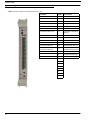
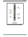
MADI Card Plus
Multichannel Audio Digital Interface Card
User Manual
MADI
Back Card
93507896000 Rev B
MADI
Front Card
08/2010
PROPRIETARY NOTICE
The product information and design disclosed herein were originated by
and are the property of Bosch Security Systems, Inc. Bosch reserves all
patent, proprietary design, manufacturing, reproduction, use and sales
rights thereto, and to any article disclosed therein, except to the extent
rights are expressly granted to others.
COPYRIGHT NOTICE
Copyright 2010 by Bosch Security Systems, Inc. All rights reserved.
Reproduction, in whole or in part, without prior written permission from
Bosch is prohibited.
WARRANTY AND SERVICE INFORMATION
For warranty and service information, refer to the appropriate web site
below:
RTS ....................................................... www.rtsintercoms.com/warranty
RTSTW ............................................................. www.rtstw.com/warranty
AudioCom......................................... www.telexaudiocom.com/warranty
RadioCom .......................................... www.telexradiocom.com/warranty
Headsets ........................................ www.intercomheadsets.com/warranty
CUSTOMER SUPPORT
Technical questions should be directed to:
Customer Service Department
Bosch Security Systems, Inc.
12000 Portland Avenue South
Burnsville, MN 55337 USA
Telephone: 877-863-4169
Fax: 800-323-0498
[email protected]
Technical Questions EMEA
Bosch Security Systems Technical Support EMEA
http://www.rtsintercoms.com/contact_main.php
AVAILABLE MADI CARD OPTIONS
MADI-16 Card ......................................................................................................................................................................... F01U169843
MADI-32 Card ......................................................................................................................................................................... F01U169844
MADI-48 Card ......................................................................................................................................................................... F01U169845
MADI-64 Card ......................................................................................................................................................................... F01U169846
MADI-16 to 32 Upgrade .......................................................................................................................................................... F01U169847
MADI-16 to 48 Upgrade .......................................................................................................................................................... F01U169848
MADI-16 to 64 Upgrade .......................................................................................................................................................... F01U169849
MADI-32 to 48 Upgrade .......................................................................................................................................................... F01U169850
MADI-32 to 64 Upgrade .......................................................................................................................................................... F01U169851
MADI-48 to 64 Upgrade .......................................................................................................................................................... F01U169852
Table
of
Contents
INTRODUCTION ................................................................................................................................... 3
Features ................................................................................................................................................................ 3
Reference Views .................................................................................................................................................. 4
Specifications ...................................................................................................................................................... 6
Connection Pin Outs ............................................................................................................................................ 7
RJ-45 Pin Outs ..................................................................................................................................................................7
Front Card DIP Switch ........................................................................................................................................ 8
Back Card DIP Switch ......................................................................................................................................... 9
System Configuration Schemes ......................................................................................................................... 10
Word Clock Configuration .............................................................................................................................................10
Fiber Configuration .........................................................................................................................................................11
Coaxial Configuration .....................................................................................................................................................11
TV Sync Configuration ...................................................................................................................................................12
Serial Pass-Through Configuration .................................................................................................................................12
Trunking Configuration ..................................................................................................................................................13
INSTALLATION ................................................................................................................................... 15
Requirements ..................................................................................................................................................... 15
How to Install .................................................................................................................................................... 15
Card Installation ..............................................................................................................................................................15
Cable the System .............................................................................................................................................................16
Configure your MADI 16 Plus Card ...............................................................................................................................16
WINDOW DESCRIPTIONS ................................................................................................................. 17
MADI Card Configuration Window ................................................................................................................. 17
Slot Display Column .......................................................................................................................................................17
Description Display Column ...........................................................................................................................................18
Ports Display Column (1) ...............................................................................................................................................18
Ports Display Column (2) ...............................................................................................................................................18
Type Display Column .....................................................................................................................................................18
Reference Clock Drop Down Column ............................................................................................................................18
Sample Rate Drop Down Column ..................................................................................................................................19
# of Channels Drop Down Column ................................................................................................................................19
Link Mode Drop Down Column .....................................................................................................................................19
Baud Rate Drop Down Column ......................................................................................................................................19
Show MADI Cards Only Check Box ..............................................................................................................................19
MADI Channel Mapping Window .................................................................................................................... 20
Card Slot Group Box 20
Card Slot Drop Down List ..............................................................................................................................................20
Show MADI Cards Only Check Box ..............................................................................................................................20
Entry Display Column ....................................................................................................................................................20
Port Display Column .......................................................................................................................................................20
Alpha Display Column ...................................................................................................................................................21
MADI Channel Drop Down Column ..............................................................................................................................21
Muted? Check Box Column ............................................................................................................................................21
Show Unavailable Channels Check Box ........................................................................................................................21
MADI Card Status Window ..............................................................................................................................22
Slot Display Column .......................................................................................................................................................22
Description Display Column ...........................................................................................................................................22
Ports Display Column (1) ...............................................................................................................................................22
Ports Display Column (2) ...............................................................................................................................................22
Type Display Column .....................................................................................................................................................22
Active Link Display Column ..........................................................................................................................................23
Backup Link Display Column ........................................................................................................................................23
Status Display Column ...................................................................................................................................................23
Pass-Through Display Column .......................................................................................................................................23
MADI to Serial Display Column ....................................................................................................................................23
Serial to MADI Display Column ....................................................................................................................................23
CONFIGURATION .............................................................................................................................. 25
Channel Allocation Scheme ...............................................................................................................................25
Base 8 ..............................................................................................................................................................................25
Base 16 ............................................................................................................................................................................26
Reference Clock .................................................................................................................................................28
Sample Rate .......................................................................................................................................................29
Channel Size ......................................................................................................................................................30
Channel Mapping ...............................................................................................................................................31
Merge Channels .................................................................................................................................................35
Download Firmware ..........................................................................................................................................36
Download License File to MADI Card ..............................................................................................................37
PORT ALLOCATION TABLE ............................................................................................................. 39
Introduction ........................................................................................................................................................39
Requirements: .................................................................................................................................................................39
Port Allocation Table Window ..........................................................................................................................40
Slot Column ....................................................................................................................................................................40
Type Column ..................................................................................................................................................................40
Allocated Column ...........................................................................................................................................................41
Ports Columns (4) ...........................................................................................................................................................42
Warning Column .............................................................................................................................................................42
Warning Field .................................................................................................................................................................43
Apply Button ...................................................................................................................................................................43
Test Button ......................................................................................................................................................................43
Cancel Button ..................................................................................................................................................................43
List
of
Figures
FIGURE 1.
FIGURE 2.
FIGURE 3.
FIGURE 4.
FIGURE 5.
FIGURE 6.
FIGURE 7.
FIGURE 8.
FIGURE 9.
FIGURE 10.
FIGURE 11.
FIGURE 12.
FIGURE 13.
FIGURE 14.
FIGURE 15.
FIGURE 16.
FIGURE 17.
FIGURE 18.
FIGURE 19.
FIGURE 20.
FIGURE 21.
FIGURE 22.
FIGURE 23.
FIGURE 24.
FIGURE 25.
FIGURE 26.
FIGURE 27.
FIGURE 28.
FIGURE 29.
FIGURE 30.
FIGURE 31.
FIGURE 32.
FIGURE 33.
FIGURE 34.
FIGURE 35.
MADI 16 Plus Back Card Reference View .................................................................................... 5
Front Card DIP Switch Location .................................................................................................... 8
Back Card DIP Switch Location ..................................................................................................... 9
3 Card Word Clock Daisy Chain Wiring ...................................................................................... 10
3 Card Word Clock Hub Wiring ................................................................................................... 10
3 Card Fiber Module A and Module B Wiring ............................................................................. 11
3 Card Coaxial Wiring .................................................................................................................. 11
3 Card TV Sync Hub Wiring ........................................................................................................ 12
Serial Pass-Through Wiring .......................................................................................................... 12
MADI-16 Plus – Trunking Configuration .................................................................................... 13
MADI Card Configuration Page ................................................................................................... 17
Edit Alpha/Description Window .................................................................................................. 18
MADI Channel Mapping Window ............................................................................................... 20
MADI Card Status Window ......................................................................................................... 22
Base 16 Port Numbering Scheme Example .................................................................................. 26
Base 8 Channel Number Scheme Example .................................................................................. 26
Base Sixteen Check Box ............................................................................................................... 27
Reference Drop Down Menu ........................................................................................................ 28
Sample Rate Drop Down Menu .................................................................................................... 29
Channels Drop Down Menu ......................................................................................................... 30
Channel Mapping Page ................................................................................................................. 31
MADI Device Channel Menu ....................................................................................................... 32
Channel Mapping Page ................................................................................................................. 33
MADI Device Channel Ranges .................................................................................................... 34
MADI Merge Example ................................................................................................................. 35
I/O Card Version Information Window ........................................................................................ 36
Download Device Firmware Window .......................................................................................... 36
Success Message ........................................................................................................................... 37
Download License Popup Menu ................................................................................................... 37
Download License File Window .................................................................................................. 38
Port Allocation Table Window ..................................................................................................... 40
Type Column Options ................................................................................................................... 40
Allocated Menu Options ............................................................................................................... 41
Ports Column Options ................................................................................................................... 42
Warning Field ............................................................................................................................... 43
CHAPTER 1
Introduction
The MADI 16 Plus card (9000-7896-000) expands the ADAM system configuration capabilities by utilizing
MADI (Multi-channel Audio Digital Interface) technology to connect any AES-10 compliant device over coaxial or fiber
connections at sampling rates of 44.1kHz and 48kHz. The MADI is a point-to-point configuration which provides for little or
no delay in the transmission of audio across lines.
The MADI 16 Plus is fully scalable, allowing 16 to 64 channels of audio in and out. It supports all standard, hot-swappable and
configurable features through RTS’ AZedit configuration software.
The MADI 16 Plus card allows audio connections between intercom frames and has an RS-232/-485 serial connection for
serial pass-thru port connections. It also offers a fiber connection that provides a single mode option with a range up to 9.32
miles (15km) between ADAM frames.
Features
Installation -
The MADI 16 Plus is hot-swappable and installs in any available slot in an ADAM Intercom
System. It has an RJ-45 connection for an RS-232 or RS-485 pass-thru serial port.
Scalability -
Provides 16 to 64 individually addressable audio channels. Each initial MADI card has 16
channels, with additional channels available for purchase in increments of 16.
Word Clock and TV
Interface -
An external reference for the MADI 16 Plus, the word clock interface allows seamless
synchronization of many different audio sources.
Fiber Optic Mode -
The MADI 16 Plus provides a single mode of operation providing up to 9.32 miles or 15km
between ADAM systems.
Trunk Capable -
The MADI 16 Plus supports supplemental data control for use with the RTS’ Intelligent
Trunking.
AZedit Configuration -
Users are able to configure the audio parameters of each MADI channel in AZedit.
Pass-Thru Serial Port -
Provides a virtual serial connection over a MADI connection using an RJ-45 connection.
3
Reference Views
Reference Views
TABLE 1. MADI
16 Plus Front Card LED Reference View
Red LEDs
LED #
Green LEDs
TXing on Control Bus
23
RXing on Control Bus
22
Processing RX Message
Link Fault – Fiber A
21
Using Fiber A
Link Fault – Fiber B
20
Using Fiber B
Link Fault – Coax
19
Using Coax
PLL Unlocked
18
PLL Locked
Invalid/Error Back Card
17
Valid Back Card/FPGA
Booted
Driving Clock
16
Clock Good
15
14
13
Pass-Through: RS-485
12
Pass-Through: RS-232
Pass-Through: MADI to
Serial Data Transferred
11
Pass-Through: Serial to
MADI Data Transferred
10
Ctrl Bus: RX Byte
9
Ctrl Bus: RX Message
8
Acquired Ctrl Bus
7
6
5
4
3
2
1
0
4
Reference Views
FIGURE 1.
MADI 16 Plus Back Card Reference View
5
Specifications
Specifications
Power
Input Power
5.2Amps @ 5V (MADI Front/Back Card
Combined)
Power Consumption
26W
Audio Performance
THD+N at 1KHz, 0.4%
Frequency Response
within ±1dB from 20Hz - 20kHz
Channel Support
56 Channels
64 Channels
Connections
Type: Word Clock BNC Connectora
Sample Rate
48KHz
44.1KHz
Type: TV Sync BNC Connectora
TV Signal Input
1Volt p-p
Type: Fiber Optic
LC Connector
Single Mode
Distance: 15km (9.32 miles)
Type: Serial Pass-Through Port
RS232/485 using an RJ-45 connector
Environmental
Weight:
Front Card: .88lbs (.40kg)
Back Card: .42lbs (.19kg)
Temperature
Operating
0°C to 50°C (32°F to 122°F)
Storage
-40°C to 70°C (-40°F to 158°F)
a. Use RG59/U 75 Ohm cable type for best results
6
NOTE:
The fiber optic transceivers provide Class 1 eye
safety by design and do not emit accessible
laser radiation levels in excess of the
acceptable emission limit (AEL) within the
inherent design or intended use of the laser.
Exempt, do not pose a hazard under normal
operating conditions. These low powered lasers
are incapable of producing injury when used as
designed and intended and are exempt from
engineering and administrative controls. A
Class 1 laser could potentially have an
embedded higher class inside of it. During
service procedures with service panels
removed and interlocks bypassed, it might be
necessary to comply with higher class laser
control measures during the service / repair
procedure. Class 1 includes lasers that were
formerly classified as Class 2a.
Connection Pin Outs
Connection Pin Outs
RJ-45 Pin Outs
RJ-45
PIN
Function
1
TXD RS-232 Received Data or RS-485+
2
RXD RS-232 Transmitted Data or RS-485-
3
GND
4
N/A
5
N/A
6
N/A
7
N/A
8
N/A
7
Front Card DIP Switch
Front Card DIP Switch
FIGURE 2.
Front Card DIP Switch Location
DIP Switch
8
Description
Switch Position
8
Debug Only Mode
Must be left in off position
7
Debug Only Mode
Must be left in off position
6
n/a
Must be left in off position
5
n/a
Must be left in off position
4
n/a
Must be left in off position
3
n/a
Must be left in off position
2
n/a
Must be left in off position
1
n/a
Must be left in off position
Back Card DIP Switch
Back Card DIP Switch
FIGURE 3.
Back Card DIP Switch Location
DIP Switch
Description
Switch Position
1
Selects either RS-485 or
RS-232 for the serial
pass-through port.
Off (default) - RS-485
On - RS-232
2
n/a
3
n/a
4
n/a
9
System Configuration Schemes
System Configuration Schemes
Word Clock Configuration
FIGURE 4.
FIGURE 5.
10
3 Card Word Clock Daisy Chain Wiring
3 Card Word Clock Hub Wiring
System Configuration Schemes
Fiber Configuration
FIGURE 6.
3 Card Fiber Module A and Module B Wiring
Coaxial Configuration
FIGURE 7.
3 Card Coaxial Wiring
11
System Configuration Schemes
TV Sync Configuration
FIGURE 8.
3 Card TV Sync Hub Wiring
Serial Pass-Through Configuration
FIGURE 9.
12
Serial Pass-Through Wiring
System Configuration Schemes
Trunking Configuration
FIGURE 10.
MADI-16 Plus – Trunking Configuration
13
System Configuration Schemes
14
CHAPTER 2
Installation
Requirements
You must have the following:
•
•
•
•
AZedit v3.9.0 or later
Master Controller v2.2.0 or later
MADI 16 Plus v2.0.0 or later
If using a multi frame system, with DBX:
DBX v1.23.0 or later
PeriphII-e v 1.23.0 or later
How to Install
Use the following instructions for your initial setup of a MADI 16 Plus Card.
CAUTION: If you do not follow these instructions, the MADI card may not work properly.
Card Installation
To install the MADI 16 Plus front and back card, do the following:
1.
Gently insert the MADI 16 Plus front card into the front of the ADAM frame.
2.
Tighten the MADI 16 Plus front card.
CAUTION:Do not fully tighten the front card into the frame.
3.
From the back of the ADAM frame, insert the back card, aligning it with the front card.
4.
Ensure the back card is properly seated against the MADI 16 Plus front card and is sitting firmly in the frame.
5.
Tighten the back card to the frame.
6.
Fully tighten the MADI 16 Plus front card.
IMPORTANT: If you remove the MADI 16 Plus back card after installing it, and then replace it. You must reboot
the MADI 16 Plus front card.
15
Installation
Cable the System
Using the information in “System Configuration Schemes” on page 10, determine what type of configuration you are going to
use for your system.
Configure your MADI 16 Plus Card
To configure your MADI 16 Plus Card, do the following:
16
Step 1
Select your Channel Allocation Scheme, see “Channel Allocation Scheme” on page 25.
Step 2
Set the Reference Clock for the MADI 16 Plus, see “Reference Clock” on page 28.
Step 3
Set the Sampling Rate for the MADI 16 Plus, see “Sample Rate” on page 29.
Step 4
Set the Channel Size for the MADI 16 Plus, see “Channel Size” on page 30.
Step 5
Map the channels of your MADI 16 Plus, see “Channel Mapping” on page 31.
CHAPTER 3
Window Descriptions
MADI Card Configuration Window
FIGURE 11.
MADI Card Configuration Page
Slot Display Column
The Slot display column shows the location of the card in relation to the frame the card resides and its position in the frame.
For example, 2:017 indicates the card is in frame two (2) and slot 17 of the card in the frame. The MADI 16 Plus can be put in
any slot in the frame.
17
MADI Card Configuration Window
Description Display Column
The Description display column shows the unique description of the card. This description can be created or modified in the
I/O Status Description window.
To create or modify the description, do the following:
1.
From the Alpha menu in AZedit, select I/O Card.
The I/O Card Description window appears.
2.
Double-click the slot entry where the card resides.
The Edit Alpha/Description window appears.
FIGURE 12.
Edit Alpha/Description Window
3.
In the Description field, enter a description for the card.
4.
Press Done.
The Edit Alpha/Description window closes.
Ports Display Column (1)
The Ports display column shows the ports assigned to the card.
Ports Display Column (2)
The Ports display column shows the ports assigned to the card.
Type Display Column
The Type display column shows the type of card in the slot (for example, MADI-16, AIO-16, etc.).
Reference Clock Drop Down Column
The Reference Clock drop down column is used to select the type of clock the MADI card uses to synchronize its
transmissions.
Available selections for this field are:
18
Internal -
The MADI card generates its own clock which is used to synchronize transmissions
MADI Stream -
The clock is retrieved from the MADI stream.
NTSC/PAL -
The clock is sent from the NTSC (National Television System Committee)/PAL (Phase
Altering Line) connection.
Word -
The clock from a Word Clock driver is used to synchronize the MADI transmissions.
MADI Card Configuration Window
Sample Rate Drop Down Column
The Sample Rate drop down column is used to select the speed the MADI card references for transmission.
IMPORTANT:
•
•
When Word Clock is selected as the type of clock, the sample rate must match the Word Clock driver.
When Internal or NTSC/PAL is selected as the type of clock, the sample rate must match the device at
the other end of the connection.
Available selections for this field are: 44.1KHz and 48.0KHz
# of Channels Drop Down Column
The # of Channels drop down column is used to select the number of channels on the MADI card. The MADI card can have
up to 64 channels assigned to each card.
Available selections for this field are: 56 and 64
Link Mode Drop Down Column
The Link Mode drop down column is used to select the connector you want use. For connector locations, see Figure 1 on
page 5.
NOTE:
Redundancy is only supported between singular point-to-point connections.
Available selections for this field are:
Fiber A -
The signal is sent over the Fiber A connection.
Fiber B -
The signal is sent over the Fiber B connection.
Fiber A and B -
The signal is sent over the Fiber A connection, however, if Fiber A fails or is
damaged, the Fiber B connection takes over sending the MADI stream.
Coax -
The signal is sent over the coaxial connection.
Baud Rate Drop Down Column
The Baud Rate drop down column is used to select the baud rate for the serial port.
Available selections for this field are:
None
9600bps
19.2Kbps
38.4Kbps
Show MADI Cards Only Check Box
The Show MADI Cards Only check box indicates only MADI cards are displayed in the window.
19
MADI Channel Mapping Window
MADI Channel Mapping Window
The MADI Channel Mapping window, shown in Figure 13, is used to map the available MADI channels to available
intercom ports in the system.
FIGURE 13.
MADI Channel Mapping Window
Card Slot Group Box
Card Slot Drop Down List
The Card Slot drop down list is used to select the card you want to configure.
Show MADI Cards Only Check Box
The Show MADI Cards Only check box indicates to only show MADI cards in the Card Slot drop down list.
The default is to display all cards in the system.
Entry Display Column
The Entry display column displays the number of audio channels you have available to use for the selected MADI card.
Port Display Column
The Port display column shows the port number associated with the entry.
20
MADI Channel Mapping Window
Alpha Display Column
The Alpha display column shows the alpha of the selected port. Alphas can be 4-, 6-, or 8-character names depending on the
configuration of AZedit.
REFERENCE: For more information on configuring AZedit, see the AZedit User Manual (P/N 93507769000).
MADI Channel Drop Down Column
The MADI Channel drop down column is used to select the MADI channel associated with the intercom port. You can have
up to 64 channels to choose from.
Available selections for this field are:
– (hyphen)
No channels are assigned
Channels 1-64
Muted? Check Box Column
The Muted? check box column is used to mute the transmit and receive channel audio.
By default, Muted? is not selected.
Show Unavailable Channels Check Box
The Show Unavailable Channels check box is used to display all channels in the system whether they are available for
assignment or not.
The default is to show only available channels.
21
MADI Card Status Window
MADI Card Status Window
FIGURE 14.
MADI Card Status Window
Slot Display Column
The Slot display column shows the slot location of the card in the intercom system.
Description Display Column
The Description display column shows the description assigned to the slot.
Ports Display Column (1)
The Ports display column shows the first eight (8) channels assigned to the slot.
REFERENCE: For more information on channel numbering schemes, see “Channel Allocation Scheme” on page 25.
Ports Display Column (2)
The Ports display column shows the second eight (8) channels assigned to the slot.
REFERENCE: For more information on channel numbering schemes, see “Channel Allocation Scheme” on page 25.
Type Display Column
The Type display column shows the type of card in the slot (i.e., MADI-16, AIO-16, etc.).
22
MADI Card Status Window
Active Link Display Column
The Active Link display column shows the status of the active link (Fiber A, Fiber B, or Coax).
There are two (2) status message possibilities: OK and Bad
Backup Link Display Column
The Backup Link display column shows the status of the backup link, if configured. This column is blank if the card is not
configured for redundant fiber, link mode set to Fiber A+B. See “Link Mode Drop Down Column” on page 19.
NOTE:
The backup link can never be Coax.
There are two (2) status message possibilities: OK and Bad
Status Display Column
The Status display column shows status of the MADI card in the slot.
There are four (4) status message possibilities:
OK
Wrong Back Card -
The wrong back card is installed.
FPGA Boot Failure PLL Unlocked -
Pass-Through Display Column
The Pass-Through display column shows type pass-through connection being used.
Available selections for this field are: RS-232 and RS-485
MADI to Serial Display Column
The MADI to Serial display column shows the number of bytes received on the MADI link and transmitted out on the serial
connection.
Serial to MADI Display Column
The Serial to MADI display column shows the number of bytes received on the Serial connection and transmitted out on the
MADI link.
23
MADI Card Status Window
24
CHAPTER 4
Configuration
The MADI-16 Plus is almost entirely configured using RTS’ AZedit configuration software. You can set the channel allocation
scheme, set the speed, set the synchronization source, select the channel size, map channels, configure a redundant fiber
connection, set the volume, and upgrade MADI firmware.
IMPORTANT:
A maximum of four (4) MADI 16 Plus cards can be used in a single frame.
Channel Allocation Scheme
Each ADAM frame slot, 17 in total, is capable of supporting 16 channels of audio. Depending on your frame construction,
there are two (2) configuration options that are supported by the MADI-16 Plus—Base 8 (standard density) and Base 16 (high
density).
By default, the channel allocation scheme is set to Base 8.
Base 8
The Base 8 channel numbering system splits 16 channels between a top and bottom group. The bottom group starts with
channels 1–136, the top group consists of channels 137–272 (see Figure 15).
EXAMPLE:If you have an AIO-16 in slot one, channels 1–8 and 137–144 are used by the AIO-16 card. Alternatively,
if you have AIO-16s in slots 1 and 3, and an AIO-8 in slot 2, the following channel mapping applies:
AIO-16 channels 1–8 and 137–144
AIO-8 channels 9–16, Channels 145–161 are not used when an AIO-8 is in the slot.
AIO-16 channels 17–33 and 162–178
25
Configuration
FIGURE 15.
Base 8 Channel Number Scheme Example
Base 16
Unlike the Base 8 channel numbering scheme, where the channels are split into an upper and lower set of eight (8), the Base
16 channel numbering scheme puts all 16 channels in one (1) slot. This means, when you configure your intercom system to
support Base 16, slot 1 in the ADAM holds channels 1–16, slot 2 holds channels 17–32, slot 3 holds 33 through 48, and so on.
FIGURE 16.
26
Base 16 Port Numbering Scheme Example
Configuration
To set the port configuration scheme, do the following:
1.
From the Options menu in AZedit, select Frame Mapping Table....
The Frame Mapping Table window appears.
FIGURE 17.
2.
Base Sixteen Check Box
Clear the Base 16 check box for the frame you want Base 8 channel configuration.
OR
Select the Base 16 check box for the frame you want Base 16 channel configuration.
27
Configuration
Reference Clock
The Reference Clock for the MADI stream can come from one (1) of four (4) different sources:
Internal -
The MADI stream is set by the internal clock on the MADI card.
MADI Stream -
The MADI stream is set by the incoming MADI stream.
NTSC/PAL -
The MADI stream is set by the NTSC/PAL (TV Sync) source.
Word Clock -
The MADI stream is set by the Word Clock.
To set the reference clock, do the following:
1.
From the System menu in AZedit, select Miscellaneous|MADI Configuration.
The MADI Configuration window appears.
2.
On the MADI configuration tab, find the MADI card you are configuring.
FIGURE 18.
28
Reference Drop Down Menu
3.
From the Reference Clock column drop down menu, select the Reference Clock Source you want to use.
4.
Send the changes to the Matrix.
Configuration
Sample Rate
The MADI-16 Plus has two (2) sampling speeds it can run—44.1kHz and 48.0kHz.
To set the sample rate, do the following:
1.
From the System menu in AZedit, select Miscellaneous|MADI Configuration.
The MADI Configuration window appears.
2.
On the MADI configuration tab, find the MADI card you are configuring.
FIGURE 19.
Sample Rate Drop Down Menu
3.
From the Sample Rate column drop down menu, select the sample rate you want to use.
4.
Send the changes to the Matrix.
29
Configuration
Channel Size
MADI devices support either 56 or 64 channels. When connecting a MADI device to the ADAM frame, you must configure
AZedit with the channel size of the MADI device. This is so you can map the MADI channels correctly.
To set the channel size, do the following:
1.
From the System menu in AZedit, select Miscellaneous|MADI Configuration.
The MADI Configuration window appears.
2.
On the MADI configuration tab, find the MADI card you are configuring.
FIGURE 20.
30
Channels Drop Down Menu
3.
From the Channels column drop down menu, select the channel size of the MADI device you are using.
4.
Send the changes to the Matrix.
Configuration
Channel Mapping
Channel Mapping allows you to assign specific MADI channels to particular ports. For example, if your MADI device has 56
channels of audio and each ADAM slot supports 16 channels, you may need to assign channels on the same MADI device to
different ports.
To map an individual MADI 16 Plus Channel, do the following:
1.
From the System menu in AZedit, select Miscellaneous | MADI Configuration.
The MADI Configuration window appears.
2.
Click the MADI Channel Mapping tab.
The MADI Channel Mapping page appears.
FIGURE 21.
3.
Channel Mapping Page
From the Card Slot drop down menu, select the MADI 16 Plus card you want to assign a MADI device channel.
NOTE: If you are using multiple types of cards (i.e., RVON-16, AIO-16, etc.) in your frame, select the Show MADI
cards only check box to only show MADI cards. This makes it easier for you to select the card you want to
assign channels to.
4.
From the MADI Channel column, select the MADI device channel you want to assign to the MADI 16 Card.
31
Configuration
5.
Click the Channel drop down menu.
A list of available MADI device channels appear.
FIGURE 22.
32
MADI Device Channel Menu
6.
Select the MADI device channel you want to assign.
7.
Click the activate icon
to send the assignment to the matrix.
Configuration
To map multiple MADI device channels at the same time, do the following:
1.
From the System menu in AZedit, select Miscellaneous | MADI Configuration.
The MADI Configuration window appears.
2.
Click the MADI Channel Mapping tab.
The MADI Channel Mapping page appears.
FIGURE 23.
3.
Channel Mapping Page
From the Card Slot drop down menu, select the MADI 16 Plus card you want to assign MADI device channels.
NOTE: If you are using multiple types of cards (i.e., RVON-16, AIO-16, etc.) in your frame, select the Show MADI
cards only check box to only show MADI cards. This makes it easier for you to select the card you want to
assign channels to.
4.
From the MADI Channel column, select the device channels you want to assign to the MADI 16 Card.
NOTE: To select random channels, hold the Ctrl key down on the keyboard and click the individual channels you
want to assign.
The channels you select are highlighted.
OR
To select a group of channels, hold the Shift key down on the keyboard, then click the first channel and last
channel in the group.
All the channels between the first and last channel are highlighted.
33
5.
Click the Channel drop down menu.
A list of available channel ranges appear.
FIGURE 24.
MADI Device Channel Ranges
6.
Select the channel range you want to assign.
7.
Click the activate icon
to send the assignment to the matrix.
Configuration
Merge Channels
A Merge is where an certain amount of MADI channels from one (1) MADI device is combined with a certain amount of
channels from another MADI device to build a total system of up to 64 channels. MADI channel mapping and merging
associates ADAM channels to MADI channels.
ADAM Channels -
the channels are located on the ADAM frame.
MADI Channels -
the channels are located on the MADI stream.
A merge can work on a Fiber or Coaxial connection. Use Figure 6 or Figure 7 on page 11, to wire your cards appropriately.
FIGURE 25.
MADI Merge Example
The example shown in Figure 25 shows two (2) MADI devices sending 8 channels each to one (1) MADI 16 Plus Card. The
audio path for the channels is as follows:
EXAMPLE: Device 1 sends eight (8) channels (MADI channels 1–8) to the MADI card (2). The MADI card sends
eight (8) more channels (MADI channels 9–16) to Device 3. Device 3 takes and replaces all 16
channels and sends those 16 channels to Device 1. When Device 1 receives the 16 MADI channels, it
takes its eight (8) channels (1–8) and replaces them with new data and passes the 16 channels to the
MADI card. When the MADI card receives the 16 channels from Device 1, it takes its channels
(9–16) and replaces them and sends them on to Device 3 which takes and replaces all 16 channels and
forwards it on. This continues as long as the data path is open.
IMPORTANT:
It is critical to assign channels correctly in the MADI Channel Mapping window. For more information,
see “MADI Channel Mapping Window” on page 20.
35
Configuration
Download Firmware
To download new firmware to the MADI 16 Plus card, do the following:
1.
From the Status menu in AZedit, select Software Versions|I/O Cards.
The I/O Card Versions window appears.
FIGURE 26.
2.
I/O Card Version Information Window
Right-click the MADI card you want download firmware to.
A Download Firmware menu option appears.
NOTE:
3.
Select Download Firmware.
The Download Firmware window appears.
4.
Navigate to the .hex file you want to download.
5.
Click Open.
The Download Device Firmware window appears.
FIGURE 27.
6.
36
To select multiple MADI 16 Plus cards, hold down the Ctrl key while you click the MADI cards.
Download Device Firmware Window
Click Begin Download.
The download begins. This takes a minute or two to occur. A success message appears when the download is finished
in AZedit.
Configuration
7.
Click OK.
The success message and the Download Device Firmware window close.
FIGURE 28.
Success Message
8.
From the Status menu, select I/O Cards.
The I/O Card Status window appears.
9.
Verify the MADI 16 Plus firmware has been updated.
IMPORTANT:
Do not power down the frame or remove the MADI 16 Plus card from the frame until you have verified
the new version information from AZedit. If the card loses power during download, undesirable results
may occur.
Download License File to MADI Card
To download the license file, do the following:
1.
From the I/O Version window, right-click the MADI card you want to upgrade.
A popup menu appears.
FIGURE 29.
2.
Download License Popup Menu
From the popup menu, select Download license....
The License Download window appears.
37
Configuration
3.
Navigate to the license file.
4.
Click Open.
The Download License File window appears.
FIGURE 30.
38
Download License File Window
5.
Click Begin.
The license file is downloaded. A success message appears once the file is done downloading.
6.
From the Status menu, select I/O Card Status.
The I/O Card Status window appears.
7.
Verify the download was successful.
APPENDIX A
Port Allocation Table
Introduction
The Port Allocation Table is used to support I/O cards with more than 16 ports. It allows you to select which card types
occupy which intercom slots and which ports are allocated to each card. Ports can be allocated in groups of four (4). Each
group contains 16 ports. Each MADI card can have no more than 64 ports per card.
NOTE:
If you are running a single frame system, the single frame can hold up to 880 ports; if you are running a multiframe Tribus system, you are limited to 256 ports per frame.
IMPORTANT:
Check power limitations of each frame before building large intercom systems.
Requirements:
The Port Allocation Table requires the following minimum firmware versions:
•
•
•
AZedit V3.9.0
MCII-e V2.3.0
DBX V1.24.0, w/PCII-e V1.24.0
To navigate to the port allocation table in AZedit, do the following:
>
From the Options menu, select Port Allocation Table.
The Port Allocation Table window appears.
39
Port Allocation Table Window
Port Allocation Table Window
FIGURE 31.
Port Allocation Table Window
Slot Column
The Slot column displays the number of the slot where the card resides.
This field is not editable.
Type Column
The Type column is used to select the type of card in the slot. Use the drop down menu to select the type of card in the slot.
Available options are: AIO-8, AIO-16, RVON-8, RVON-16, MADI-16, MADI-32, MADI-48, MADI-64, and AES-3.
FIGURE 32.
40
Type Column Options
Port Allocation Table Window
Allocated Column
The Allocated column is used to select the number of ports to allocate. Use the drop down menu to select the number of ports
you want to allocate.
Available options are:
8-
Used to allocate 8 ports in a Base 8 system.
8+8 -
Used to allocate 16 ports in a Base 8 system.
16 -
Used to allocate 16 ports in a Base 16 system.
24 -
Used to allocate 24 ports in a Base 16 system.
32 -
Used to allocate 32 ports in a Base 16 system.
40 -
Used to allocate 40 ports in a Base 16 system.
48 -
Used to allocate 48 ports in a Base 16 system.
56 -
Used to allocate 56 ports in a Base 16 system.
64 -
Used to allocate 64 ports in a Base 16 system.
FIGURE 33.
Allocated Menu Options
41
Port Allocation Table Window
Ports Columns (4)
The Ports column is used to assign ports in either groups of eight (8) or 16 ports, depending on what is selected in the
Allocated column.
Up to four (4) groups of 16 ports are allowed.
TIP:
To assist in setup and configuration debug, assign consecutive port numbers for multi-group port columns.
NOTE:
The Ports column only becomes active for the number of ports you are allocating. For example, if you have 32
ports, only the first two (2) Ports columns are enabled.
FIGURE 34.
Ports Column Options
Warning Column
The Warning column displays a warning when configured card types do not match detected card types and when not all ports
are allocated (for a given card, or for the intercom as a whole).
42
Port Allocation Table Window
Warning Field
The Warning field displays warnings pertaining to the intercom system as a whole.
FIGURE 35.
Warning Field
Apply Button
The Apply button is used to apply any modifications made to the port allocation table to the intercom system while the
window remains open.
Test Button
The Test button is used to test the modifications you made to the port allocation table before you apply it to the intercom
system. A message displays when the test is finished notifying you if the port allocation table is valid or not.
Cancel Button
The Cancel button is used to close the window without implementing any of the modifications made to the port allocation
window.
43
Bosch Security Systems, Inc.
12000 Portland Avenue South
Burnsville, MN 55337 U.S.A.
www.boschcommunications.com