1
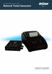
NetComm INFRASTRUCTURE Series
In-wall Wireless Access Point
USER GUIDE
Table of Contents
1. Introduction.................................................................................................................................... 4 1.1 Overview .....................................................................................................................................................4 1.2 Product Features..........................................................................................................................................4 1.3 Deployment Topology Diagram..................................................................................................................5 1.4 Document Conventions ...............................................................................................................................5 2. System Overview ........................................................................................................................... 6 2.1 Package Contents ........................................................................................................................................6 2.2 Specification................................................................................................................................................7 3. Installation ................................................................................................................................... 10 3.1 Panel Function Description .......................................................................................................................10 3.2 Hardware Installation ................................................................................................................................12 3.3 Basic Configuration...................................................................................................................................15 4. Web Interface Configuration.................................................................................................... 26 4.1 System Configuration................................................................................................................................27 4.1.1 System Information .......................................................................................................................................27 4.1.2 Network Settings ...........................................................................................................................................29 4.1.3 Management Services ....................................................................................................................................30 4.2 Wireless .....................................................................................................................................................31 4.2.1 Virtual AP Overview......................................................................................................................................31 4.2.2 General Settings.............................................................................................................................................33 4.2.3 VAP Configuration.........................................................................................................................................35 4.2.4 Security Settings ............................................................................................................................................36 4.2.5 Repeater Settings ...........................................................................................................................................39 4.2.6 Advanced Wireless Settings...........................................................................................................................41 4.2.7 Access Control Settings .................................................................................................................................40 4.2.8 Site Survey.....................................................................................................................................................42 4.3 Firewall .....................................................................................................................................................44 4.3.1 Layer 2 Firewall Settings...............................................................................................................................44 4.3.2 Firewall Service .............................................................................................................................................52 4.3.3 Advanced Firewall Settings ...........................................................................................................................50 4.4 Utilities......................................................................................................................................................51 4.3.1 Change Password...........................................................................................................................................51 4.3.2 Network Utilities ...........................................................................................................................................52 4.3.3 Configuration Save & Restore .......................................................................................................................53 4.3.4 System Upgrade.............................................................................................................................................54 4.3.5 Reboot............................................................................................................................................................55 4.5 Status .........................................................................................................................................................56 4.5.1 System Overview...........................................................................................................................................56 4.5.2 Associated Client Status ................................................................................................................................61 NP727 User’s Manual V1.00
4.5.3 Repeater Information .....................................................................................................................................62 4.5.4 Event Log ......................................................................................................................................................61 4.6 Online Help ...............................................................................................................................................62 NP727 User’s Manual V1.00
1. Introduction
1.1 Overview
The NP727 In-wall Wireless Access Point is an in-the-wall Wi-Fi IEEE 802.11b/g AP, designed to blend with any
office or home interior architecture and furnishings effortlessly.
The compact NP727, with its small form factor can fit in a standard wall outlet box, and hides the wall cutout with its
faceplate. Its front panel features LED status indicators and an RJ45 wall jack. It has the interfaces to serve both
wireless and wired LAN access. The simplistic yet stylish design of NP727 allows it to blend into a working or a
living environment seamlessly.
By utilizing Power over Ethernet (PoE), the NP727 comes with an advantage of running fewer cables in the duct.
The Power over Ethernet (PoE) LAN port on the NP727 serves as the power feed as well as the wired network
feed. Alternatively, it can also be powered via an AC adapter when a PoE switch is not available.
The NP727 is an easy-to-install and cost-effective solution for most indoor wireless deployments, including hotel
rooms, apartments, offices, classrooms, libraries, private homes and public kiosks etc.
1.2 Product Features
y
Installation friendly housing design for seamless blending into deployed environment
y
High speed IEEE 802.11g and backward compatible with 802.11b
y
Supporting IEEE 802.3af Power over Ethernet (PoE)
y
WDS for extending wireless coverage
y
Supporting QoS & 802.11e WMM
y
Multiple virtual APs & capable of client isolation
y
Business-class WLAN security & client authentication
y
Layer 2 firewall for security enhancement
NP727 User’s Manual V1.00
1.3 Deployment Topology Diagram
This above deployment scenario illustrates a deployment example.
y
Hidden in-the-wall behind faceplate, blending into most interior/architectural designs.
y
Keep the style of a simple LAN wall jack while being able to serve both LAN and WLAN devices.
y
When managed under a NetComm Internet Access Controller, the combination has been pre-integrated to
provide solutions for many applications.
1.4 Document Conventions
Represents essential steps, actions, or messages that should not be ignored.
Note:
Contains related information that corresponds to a topic.
Indicates that clicking this button will save the changes you made, but you must reboot the
system upon the completion of all configuration settings for the changes to take effect.
Indicates that clicking this button will clear what you have set before the settings are
applied.
NP727 User’s Manual V1.00
2. System Overview
2.1 Package Contents
The standard package of the NP727 includes:
y
NP727 x 1
y
Screws & Face Plate Kit x 1
y
Product CD-ROM x 1
NP727 User’s Manual V1.00
2.2 Specification
Standard Conformance
h Wireless:
(1) IEEE 802.11g (up to 54Mbps)
(2) IEEE 802.11b (up to 11Mbps)
h Ethernet:
(1) 802.3
(2) 802.3u
Wireless Radio
h Frequency band: 2.4 GHz
h Wireless architecture:
(1) AP mode
(2) Repeater mode (WDS/Universal Repeater)
h Modulation:
(1) 802.11b: DSSS (CCK, DBPSK, DQPSK)
(2) 802.11g: OFDM (64-QAM, 16-QAM, QPSK, BPSK)
h Channels:
(1) Australia (Channel 1~13)
h Data rate with auto fallback: 54, 48, 36, 24, 18, 12, 11, 9, 6, 5.5, 2, and 1 Mbps
h Receiver Sensitivity:
(1) 802.11g: 54Mbps@-74dBm
(2) 802.11b: 11Mbps@-89dBm
h RF output power:
(1) EU/AU: 100mW EIRP
*Note: EIRP= Transmit Power + Antenna Gain
h Antenna: Built-in chip antenna
Wireless Signal Management
h Max number of ESSIDs (Virtual APs): 8
h Max number of associated clients per AP: 32
h Setting for maximum number of associated clients
h Network policy based on ESSID
QoS & WMM
h DiffServ / TOS
h IEEE 802.1p/ COS
h IEEE 802.1Q Tag VLAN priority control
h IEEE 802.11e WMM
Handover & Roaming
h IEEE 802.11f IAPP
h IEEE 802.11i pre-auth (PMKSA cache)
h L2 Roaming
NP727 User’s Manual V1.00
System Management
h Web-based administration
h SNMP v1/v2c
h Provides Event Log
h Syslog information support
h Statistics
h Configuration backup and restore
h One-button-click to restore factory default setting
h Firmware upgrade
h Capable of performing RADIUS Accounting and Accounting Update
Security
h WEP (64/128/152 bits)
h EAP-TLS + Dynamic WEP
h EAP-TTLS + Dynamic WEP
h PEAP / MS-PEAP + Dynamic WEP
h WPA (PSK + TKIP)
h WPA (802.1X certification + TKIP)
h 802.11i WPA2 (PSK + CCMP / AES)
h 802.11i WPA2 (802.1X certification + CCMP / AES)
h Setting for TKIP / CCMP / AES key's refreshing period
h Hidden ESSID support
h MAC Address filtering (MAC ACL)
h MAC authentication with RADIUS servers
h Maximum number of registered RADIUS servers: 2
Built-in Servers & Client Interfaces to Other Services
h DHCP client
h DNS client
h Syslog client
h RADIUS client
h SNMP v1/v2c read & write client
Physical and Power
h Form factor: In-Wall type
h Dimensions (W x H x D):
Center unit: 1.88" x 3.07" x 3.07" (48mm x 78 mm x 78 mm)
Faceplate: 2.95" x 4.72" x 0.35" (75mm x 120 mm x 9 mm)
h Weight: 0.42 lbs (0.19 kg)
h PoE port: IEEE 802.3af
h Power adaptor (Optional, not included in the package):
AC Input: 100~240 VAC, 50~60 Hz
DC Output: 12VDC, 1.5A
Connectors and Display
h LAN Port: 1 × 10/100 Base-T Ethernet
NP727 User’s Manual V1.00
h PoE Port: 1 × 10/100 Base-T Ethernet
h LED Indicators: 1 × Power, 1 × LAN, 1 × WLAN
Environment
h Operation Temperature: -20 ~ 50 °C
h Storage Temperature: -20 ~ 70 °C
h Operation Humidity: 10% ~ 80% Non-condensing
h Storage Humidity: 5% ~ 90% Non-condensing
Certifications
h FCC, CE
h RoHS compliant
NP727 User’s Manual V1.00
3. Installation
3.1 Panel Function Description
On the front panel of the NP727, there are three LEDs that are used to indicate the POWER status, the WLAN
status, and the link status of the LAN port. On the front panel, there are: one RESET button and one LAN port. The
antenna is built-in chip antenna.
Front Panel
1.
2.
RESET Button:
¾
Press the button to restart the system.
¾
Press the button for more than 30 seconds to reset the system to default settings.
LAN:
¾
The LAN port is for connection with wired networks.
LED status indication:
3.
LAN
¾
4.
WLAN
¾
5.
OFF indicates no connection; ON indicates connection; BLINKING indicates transmitting data.
Green LED ON indicates system ready.
Power
¾
Green LED On indicates power on; OFF indicates power off.
NP727 User’s Manual V1.00
In-Wall Panel
1.
POWER SOCKET:
¾
2.
Attach the power adapter here, it accepts 12VDC 1.5A.
PoE (LAN):
¾
The LAN port is for connection with wired networks or PoE Switch.
NP727 User’s Manual V1.00
3.2 Hardware Installation
Please follow the steps mentioned below to install the hardware of the NP727:
Before the installation, assemble the following parts accordingly for the in-wall placement.
Step 1: Unpack the box and remove the cover and the frame.
Step 2: Lock the screw correctly to the frame.
Step 3: Slide the frame from the two sides to the front until locked to the fixed point.
NP727 User’s Manual V1.00
Step 4: Cover it with faceplate.
NP727 User’s Manual V1.00
1. Place the NP727 in the best location.
The best location for the NP727 is usually at the center of your wireless network.
2. Connect the NP727 to your network device.
Connect one end of an Ethernet cable to the LAN port of THE NP727 and the other end of the cable to a
switch, a router or a hub. The NP727 is then connected to your existing wired LAN network.
3. There are two ways to supply power over to THE NP727.
(1) Connect the power adapter to the NP727 power socket.
(2) THE NP727 PoE (LAN) port is capable of transmitting DC currents via its PoE (LAN) port. Connect an
IEEE 802.3af-compliant PSE device, e.g. a PoE switch, to the PoE (LAN) port of THE NP727 with the
Ethernet cable.
Now, the hardware installation is completed.
NP727 User’s Manual V1.00
3.3 Basic Configuration
The NP727 supports web-based configuration. Upon the completion of the hardware installation, the NP727 can be
configured through a PC by using its web browser such as Mozilla Firefox 2.0 or Internet Explorer version 6.0 and
the above.
The default values of the LAN IP address and subnet mask of the NP727 are:
IP Address: 192.168.27.1
Subnet Mask: 255.255.255.0
•
To access the web management interface, connect the administrator PC to the LAN port of the NP727 via an
Ethernet cable. Then, set a static IP address on the same subnet mask as the NP727 in the TCP/IP of your PC,
such as the following example (Please note that the IP address used shall not be duplicated with the IP
address of other devices within the same network.):
IP Address: 192.168.1.100
Subnet Mask: 255.255.255.0
•
Launch the web browser on your PC by entering the IP address of the NP727 (http://192.168.27.1) in the
address field, and then press Enter. The following Administrator Login Page will then appear. Enter “admin”
for both the User name and Password fields, and then click Login to log in.
User name: “admin”
Password: “admin”
•
After a successful login into the NP727, a System Overview page of the web management interface will
appear. To logout, simply click on the Logout button in the upper right hand corner of the interface to return to
the Administrator Login Page.
NP727 User’s Manual V1.00
•
To logout, simply click on the Logout button at the upper right hand corner of the interface to return to the
Administrator Login Page.
NP727 User’s Manual V1.00
Please refer to the following steps to complete the basic configuration:
Step 1. Change Administrator’s Password:
h
h
Note:
Click on the Utilities button, and then select the Admin Password tab.
Enter a new password with length up to 32 characters, and then click SAVE to save the new password.
Click SAVE to save the changes, but you must reboot the system upon the completion of all
configuration settings for the changes to take effect. When clicking SAVE, the following message will
appear: “Some modifications have been saved and will take effect after Reboot.”
NP727 User’s Manual V1.00
Step 2. Configure Wireless Settings
h
h
Click on the Wireless button, and then select the General tab.
Determine the Band and Channel settings:
Select your preferred Band and Channel for your wireless connection. For example, select
802.11b+802.11g for the band and Auto for the channel.
NP727 User’s Manual V1.00
Step 3. Configure VAP (Virtual Access Point) Profile Settings
The NP727 Supports up to 8 virtual APs. By default, only 1 VAP is enabled.
h
Configure VAP profile settings:
(a) Select the VAP Config tab to configure the settings for each VAP.
(b) An administrator can enable or disable specific VAP from the drop-down list box of Profile Name.
h
Check VAP status:
After finishing the above settings, the status of enabled Virtual APs shall be reflected on the Virtual AP
Overview page.
Step 4 (Advanced Optional). Choose Security Type
NP727 User’s Manual V1.00
h
Click on the Wireless button.
h
Select the Security tab to configure your preferred security types:
(The following uses “VAP-1” security configuration as an example.)
NP727 User’s Manual V1.00
1. Choose “WEP” as its Security Type:
When WEP is selected, provide the desired Authentication, key length, format, index and values.
NP727 User’s Manual V1.00
2. Choose “802.1X” as its Security Type:
When 802.1X authentication is selected, provide the desired WEP key length and the corresponding
settings of RADIUS server.
NP727 User’s Manual V1.00
3. Choose “WPA-PSK” as its Security Type:
When WPA-PSK is selected, provide the desired pre-shared key and Cipher Suite.
4. Choose “WPA-Radius” as its Security Type:
When WPA-Radius is selected, provide the Cipher type and the corresponding settings of RADIUS
server.
NP727 User’s Manual V1.00
Step 5. Configure WDS (Wireless Distribution System) Settings
To extend its wireless coverage, the NP727 is capable of creating WDS links for connection to other WDS-capable
APs (peer APs). The NP727 supports up to 4 WDS links; by default, all WDS profiles are disabled.
h
Click on the Repeater tab.
h
Select WDS from the drop-down list of Repeater Type.
h
Configure WDS link parameters:
(a) Select preferred Security Type
(b) Enter MAC Address of Remote AP (peer AP) and click Add
h
To configure peer AP(s):
After completing the WDS settings for the NP727 (functioning as a “primary WDS station”), you must
also configure the settings of its peer AP(s).
If you use another NP727 as the peer AP, simply repeat the above-mentioned steps with the MAC
Address of the primary WDS station for setting WDS link parameters of the peer AP(s).
NP727 User’s Manual V1.00
Step 5 (CONT). Check WDS Link Status
h
Click on the Status button.
h
Select the Repeater tab.
h
Check the signal strength of WDS link(s):
Upon the completion of Step 5, there shall be RSSI displayed on the WDS Link Status. If the RSSI is
shown as N/A, check if the wiring is properly connected and please ensure the accurate execution of
Step 5 as described above.
Congratulations!
The NP727 is now installed and configured successfully.
•
•
It is strongly recommended to make a backup copy of configuration settings.
After the NP727's network configuration is completed, please remember to change the IP Address of
your PC Connection Properties back to its original settings in order to ensure that your PC functions
properly in its real network environments.
NP727 User’s Manual V1.00
3. Web Interface Configuration
This chapter will guide you through further detailed settings. The following table shows all the UI functions of the
NP727 In-wall Wireless Access Point. In the web management interface, there are two main interface areas: Main
Menu and Working Area. The Working Area occupies the largest area of the web management interface,
displayed in the center of the interface. It is also referred as the configuration page. The web management
interface is the page where status is displayed, control is issued and parameters are configured. The Main Menu,
on the top of the web management interface, allows the administrator to traverse to various management functions
of this system. The management functions are grouped into branches: System, Wireless, Firewall, Utilities, and
Status.
OPTION
System
Wireless
Firewall
Utilities
Status
Note:
FUNCTION
System Information
Network Settings
Management Services
Virtual AP Overview
General Settings
VAP Configuration
Security Settings
Repeater Settings
Advanced Wireless Settings
Access Control Settings
Site Survey
Layer 2 Firewall Settings
Firewall Service
Advanced Firewall Settings
Change Password
Network Utilities
Configuration Save & Restore
System Upgrade
Reboot
System Overview
Associated Client Status
Repeater Information
Event Log
On each and every configuration page, you may click SAVE to save the changes, but you must
reboot the system upon the completion of all configuration settings for the changes to take effect.
When clicking SAVE, the following message will appear: “Some modifications have been saved
and will take effect after Reboot.” <All on-line users will be disconnected during
reboot/restart.>
NP727 User’s Manual V1.00
4.1 System Configuration
This section includes the following functions: System Information, Network Settings and Management
Services.
4.1.1 System Information
y
System Information
For the purpose of maintenance, it is required to specify the system name, its location and corresponding
basic parameters. Fields such as Name, Description and Location are used for mnemonic purpose. It is
recommended to have different values in each AP.
y
h
Name: The system name used to identify this system
h
Description: Further information about this installation
h
Location: The geographic location
Time
Synchronize the system time either by using NTP server or by manual setup. When NTP server is used, the
information of at least one NTP server must be provided. If FQDN (full qualified domain name) is used as the
IP address of NTP server, the DNS server must also be activated (please refer to 4.1.2 Network Settings).
h
Device Time: Current system time
h
Time Zone: Select a time zone from the drop-down list box
NP727 User’s Manual V1.00
h
Synchronization: There are two options of setting system time
1) Enable NTP:
By selecting Enable NTP, the NP727 can synchronize its system time with the NTP server
automatically. While this method is chosen, at least one NTP server's IP address should be
provided. It is recommended to provide the IP address of both NET Server 1 and 2 in case of any
NTP service failure.
2) Manually set up:
By selecting manually set up, the administrator can manually set the system date and time.
Unless the Internet connection is unavailable, it is recommended to use NTP server for time
synchronization.
NP727 User’s Manual V1.00
4.1.2 Network Settings
This page is for setting up the wired internet connections. There are two methods of IP configuration available with
the NP727. LAN interface configuration determines the way to obtain the IP address, either by DHCP or by manual
setup.
y
Mode: Determine the way to obtain the IP address, by DHCP or Static.
h
DHCP client: This option can be selected when there is a DHCP server located on your wired/wireless
network. Please make sure the network connection settings are correct and the network connection is
active.
h
Static setting: When this option is selected, the administrator can set the parameters manually. Enter the
IP Address, Netmask and Gateway provided by your ISP.
y
Primary and Secondary DNS Server: If any host information is given in FQDN format (full qualified domain
name), ensure at least one of these DNS (Domain Name Service) server IP is correct.
y
Layer 2 STP: When the system is configured to bridge several networks (WDS mode), this STP (Spanning
Tree Protocol) function must be enabled to avoid a loop condition and to obtain the best data path for network
communication optimization purpose.
Broadcasting storm may occur in a multi-switch environment where broadcast pockets are forwarded in an
endless loop between switches. A broadcast storm can consume up all available CPU resources and the
Internet and Ethernet bandwidth. Enabling the STP function can prevent the system from encountering such
chaos.
NP727 User’s Manual V1.00
4.1.3 Management Services
For the purpose of easy maintenance, SNMP (Simple Network Management Protocol) and remote syslog services
are provided in the NP727. The system will be managed remotely in a centralized manner.
y
VLAN for Management: The management traffic from the device can be tagged with VLAN ID. If the option is
enabled, the VLAN ID can be chosen from 1 to 4094.
y
SNMP Configuration: By enabling SNMP service, the remote SNMP manager can obtain the NP727’s
system status.
h
Community String: Specify the password for Read and Write.
h
Trap: Enable or Disable the feature. When enabled, events on Cold Start, Interface Up & Down and
Association & Disassociation can be reported to an assigned management station with specified Server
IP Address.
y
System Log: By enabling this service, specify an external syslog server to accept syslog messages from the
NP727 remotely. Thus, by reading the syslog message in the remote server, the administrator can review
activities of all installed the NP727s in the network.
h
Server Port: The port number of the server.
h
Log Level: Select the desired level of received events from the drop-down list box.
NP727 User’s Manual V1.00
4.2 Wireless
This section includes the following functions: VAP Overview, General, VAP Configuration, Security, Repeater,
Advanced, Access Control, and Site Survey. The NP727 supports up to eight Virtual Access Points (VAPs).
Each VAP can have its own settings including ESSID, VLAN ID, security settings, etc. Such VAP capability enables
different levels of service to meet actual requirements.
4.2.1 Virtual AP Overview
An overall status is collected in this page, including Enable/Disable State, Security Type, MAC ACL state, and
Advanced Settings. The NP727 has 8 VAPs; each has its own settings. In this table, please click on the hyperlink
for further configuration of each VAP respectively.
•
State: The hyperlink showing Enable or Disable connects to the screen of VAP Configuration.
NP727 User’s Manual V1.00
•
Security Type: The hyperlink showing security type connects to the screen of Security Settings.
•
MAC ACL: The hyperlink showing Allow or Disable connects to the screen of Access Control Settings.
•
Advanced Settings: The hyperlink of advanced settings connects to the screen of Advanced Wireless
Settings.
NP727 User’s Manual V1.00
4.2.2 General Settings
y
Band: The operating wireless frequency band of this system. Select one frequency band from Disable,
802.11b, 802.11g or mixed mode 802.11b+802.11g.
y
Super G: Options of Bursting, Fast Frames, and Dynamic Turbo can be selected to boost wireless
throughput.
y
Short Preamble: This option can be turned on to enable Short-Preamble frames.
y
Channel: Select the appropriate channel from the drop-down list box to correspond with your network
settings, for example, Channel 1-13 in Australia, or choose the default Auto.
y
Max Transmit Rate: Select transmit rate from 1 M to 54 M or Auto.
y
Transmit Power: Select from the lowest to highest power level or choose Auto.
y
ACK Timeout: When packet loss is increasing over longer distance, ACK Timeout can be used to alleviate
this issue.
NP727 User’s Manual V1.00
The RF settings in this page will be applied to all VAPs.
Under normal circumstances, the available RF configurations are illustrated as below:
Mode
Channel
Rate
Disable
NA
NA
802.11b
1, 2, 3, 4, 5, 6, 7, 8, 9,
10, 11, 12, 13
Auto, 1M, 2M, 5.5M, 11M
802.11g
1, 2, 3, 4, 5, 6, 7, 8, 9,
10, 11, 12, 13
Auto, 6M, 9M, 12M, 18M, 24M, 36M,
48M, 54M
802.11b+802.11g
1, 2, 3, 4, 5, 6, 7, 8, 9,
10, 11, 12, 13
Auto, 1M, 2M, 5.5M, 11M, 6M, 9M,
12M, 18M, 24M, 36M, 48M, 54M
Power
NA
Auto, Lowest, Low,
Medium, High, Highest
NP727 User’s Manual V1.00
4.2.3 VAP Configuration
To enable each VAP in the NP727, the administrator must configure each VAP manually. The settings of each VAP
are collected as its profile.
y
Enable VAP: Enable or disable VAP function.
y
Profile Name: The profile name of each VAP for identity/management purpose.
y
ESSID: ESSID (Extended Service Set ID) indicates a unique SSID used by a client device to associate with a
specified VAP. ESSID determines the service level assigned to a client.
y
VLAN ID: The NP727 supports tagged VLANs (virtual LANs). To enable VLAN function, each VAP must have
a unique VLAN ID; valid values are ranged from 1 to 4094.
NP727 User’s Manual V1.00
4.2.4 Security Settings
The NP727 supports various user authentication and data encryption methods in each VAP profile. Thus the
administrator can depend on the need to provide different service levels to clients. The security type includes
None, WEP, 802.1X, WPA-PSK, and WPA-RADIUS.
y
None: No authentication required. This is the default setting as shown in the following figure.
y
WEP: Support key length of 64/128/152 bits.
NP727 User’s Manual V1.00
y
802.1X: Provide RADIUS authentication and enhanced WEP.
y
WPA-PSK: Provide shared key authentication in WPA data encryption.
NP727 User’s Manual V1.00
y
WPA-RADIUS: Authenticate users by RADIUS and provide WPA data encryption.
NP727 User’s Manual V1.00
4.2.5 Repeater Settings
The NP727 supports either WDS or Universal Repeater as options of repeater types; selecting None will turn off
this function.
♦
WDS
If WDS is chosen, the NP727 will support 4 WDS links to its peer APs. Security Type (None, WEP, or TKIP/AES)
can be configured to decide which encryption is to be used for WDS connections respectively. Please fill in remote
peer’s MAC address and click Add to add this peer into WDS list. After the settings have been configured, please
click SAVE to proceed; CLEAR button is used to clear the contents in the above WDS connection list.
NP727 User’s Manual V1.00
♦
Universal Repeater
If Universal Repeater is chosen, please provide the SSID of upper-bound AP for uplink connection; Security Type
(None, WEP, or WPA-PSK) can be configured for this Repeater connection. Please note the security type
configured here needs to be the same as upper-bound AP to be connected.
NP727 User’s Manual V1.00
4.2.6 Advanced Wireless Settings
The advanced wireless settings for the NP727’s VAP (Virtual Access Point) profiles allow customization of data
transmission settings. The administrator can tune the following parameters to improve network communication
performance if a poor connection occurs.
y
Beacon Interval: Enter a value between 25 and 500 ms. The default is 100 milliseconds. The specified value
represents the amount of time between access point beacon signal transmissions.
y
RTS Threshold: Enter a value between 1 and 2346. The default is 2346. RTS (Request to Send) Threshold
determines the packet size at which the access point (the NP727) issues a request to send (RTS) before
sending the packet to prevent the hidden node problem. The RTS mechanism will be activated if the data size
exceeds the value you set. A lower RTS Threshold setting can be useful in areas where many client devices
are associating with the NP727 or in areas where the clients are far apart and can detect only the NP727 and
not each other.
Fragment Threshold: Enter a value between 256 and 2346. The default is 2346. A packet size larger than
this threshold will be fragmented (sent in several pieces instead of one block) before transmission. A smaller
value results in smaller packets but allows a larger number of packets in transmission. A lower Fragment
Threshold setting can be useful in areas where communication is poor or disturbed by a serious amount of
radio interference.
y
Broadcast SSID: The default is Enable. Disabling this function will prevent the NP727 from broadcasting its
SSID, where only devices that have the correct SSID can connect.
y
Station Isolation: The default is Disable. By enabling this function, all stations associated with the NP727 can
only communicate with the NP727.
y
WMM: The default is Disable. Wi-Fi Multimedia (WMM) is a Quality of Service (QoS) feature that prioritizes
wireless data packets based on four access categories: voice, video, best effort, and background.
Applications without WMM and applications that do not require QoS are assigned to the best-effort category,
which receives a lower priority than voice and video. In short, WMM decides which data streams are the most
important and assign them a higher traffic priority.
< To receive the benefits of WMM QoS >
- The application must support WMM.
NP727 User’s Manual V1.00
- You must enable WMM in the NP727.
- You must enable WMM in the wireless adapter in your computer.
y
IAPP: The default is Disable. IAPP (Inter Access Point Protocol) is a protocol by which access points share
information about the stations that are connected to them. By enabling this function, the NP727 will
automatically broadcast information of associated wireless stations to its peer access points. This will help
wireless stations roam smoothly among IAPP-enabled access points in the same wireless LAN.
y
802.11g Protection: When enabled, the associated 802.11g stations will benefit from this function since their
transmission speed will not be affected by the surrounding 802.11b stations.
NP727 User’s Manual V1.00
4.2.7 Access Control Settings
y
Maximum Number of Clients
The NP727 supports various methods of authenticating clients for using wireless LAN. The default policy is
unlimited access without any authentication required. To restrict the station number of wireless connections,
simply change the Maximum Number of Stations to a desired number. For example, while the number of
stations is set to 20, only 20 stations are allowed to connect to the specified VAP.
y
Access Control Type
The selected Access Control Type will be the activated policy while the rest will be omitted. The following is
a list of the supported methods for MAC ACL control:
(1)
Disable Access Control
No MAC address check required.
(2)
MAC ACL Allow List
Deny all except those in the Allow List. When selecting MAC ACL Allow List, all wireless connections to
the specified VAP will be denied except the MAC addresses listed in the Allow List (“allowed MAC
addresses”). The administrator can disable any allowed MAC address to connect to the VAP temporarily
by checking Disable. For example, 11:22:33:44:55:66 is in the Allow List; to temporarily deny its access,
check Disable in the State section.
(3)
MAC ACL Deny List
Allow all except those in the Deny List. When selecting MAC ACL Deny List, all wireless connections to
the specified VAP will be allowed except the MAC addresses listed in the Deny List (“denied MAC
addresses”). The administrator can allow any denied MAC address to connect to the VAP temporarily by
NP727 User’s Manual V1.00
checking Enable.
(4)
RADIUS ACL
Authenticate incoming MAC addresses by RADIUS. When selecting RADIUS ACL, all incoming MAC
addresses will be authenticated by RADIUS. Please note that each VAP’s MAC ACL and its security type
(showing on the Security Settings page) share the same RADIUS configuration.
NP727 User’s Manual V1.00
4.2.8 Site Survey
If Universal Repeater function is enabled, the system can scan and display all surrounding available access points
(APs). The administrator can then select an AP to be connected to extend its wireless service coverage on this
page.
•
SSID: The SSID (Service Set ID) of the AP found in the system’s coverage area.
•
MAC Address: The MAC address of the respective AP.
•
Channel: The channel number currently used by the respective AP or repeater.
•
Rate: The transmitting rate of the respective AP.
•
Signal: The signal strength of the respective AP.
•
Security: The encryption type used by the respective AP
•
Setup/ Connect:
¾
Connect: Click Connect to associate with the respective AP directly; no further configuration is required.
¾
Setup: Click Setup to configure security settings for associating with the respective AP.
o
WEP: Click Setup to configure the WEP setting for associating with the target AP.
The following configuration box will then appear at the bottom of the screen. Security settings
configured here must be the same as the target AP.
NP727 User’s Manual V1.00
o
WPA-PSK: Click Setup to configure the WPA-PSK setting for associating with the target AP.
The following configuration box will then appear at the bottom of the screen. Information provided
here must be consistent with the security settings of the target AP.
NP727 User’s Manual V1.00
4.3 Firewall
The system provides an added security feature, L2 firewall, in addition to typical AP security. Layer-2 firewall offers
a firewall function that is tailored specifically for layer 2 traffics, providing another choice of shield against possible
security threats coming from/going to WLAN (AP interfaces); hence, besides firewall policies configured on
gateways, this extra security feature will assist to mitigate possible security breach.
4.3.1 Layer 2 Firewall Settings
It provides an overview of firewall rules in the system; 6 default rules with up to total 20 firewall rules are available
for configuration.
Layer 2 Firewall Overview
From the overview table, each rule is designated with the following fields:
♦
No.: The numbering will decide the priority to let the system carry out the available firewall rules in the
table.
♦
State: The check marks will enable the respective rules.
♦
Action: “DROP” denotes a block rule; “ACCEPT” denotes a pass rule.
♦
Name: It shows the name of the rule.
♦
EtherType: It denotes the type of traffics subject to this rule.
NP727 User’s Manual V1.00
♦
Remark: It shows the note of this rule.
♦
Setting: 4 actions are available; “Del” denotes to delete the rule, “Ed” denotes to edit the rule, “In” denotes
to insert a rule, and “Mv” denotes to move the rule.
>>To delete a specific rule,
“Del” in “Setting” column of firewall list will lead to the following page for removal confirmation. After “SAVE”
button is clicked and system reboot, the rule will be removed.
Layer 2 Firewall Settings Screen (Remove rule)
>>To edit a specific rule,
“Ed” in “Setting” column of firewall list will lead to the following page for detail configuration.
From this page, the rule can be edited from scratch or from an existing rule for revision.
Layer 2 Firewall Configuration Screen (Edit)
♦
Rule ID: The numbering of this specific rule will decide its priority among available firewall rules in the
table.
♦
Rule name: The rule name can be specified here.
NP727 User’s Manual V1.00
♦
EtherType: The drop-down list will provide the available types of traffics (ALL, IPv4, IEEE802.3, 802.1Q,
ARP, and RARP) subject to this rule.
♦
Interface: It can indicate inbound/outbound direction with desired interfaces (VAP1~VAP8)
♦
Service (when EtherType is IPv4): Select the available upper layer protocols/services from the drop-down
list.
♦
DSAP/SSAP (when EtherType is IEEE802.3): The value can be further specified for the fields in 802.2
LLC frame header.
♦
Type (when EtherType is IEEE802.3): The field can be used to indicate the type of encapsulated traffics.
♦
Vlan ID (when EtherType is 802.1Q): The Vlan ID is provided to associate with certain VLAN-tagging
traffics.
♦
Priority (when EtherType is 802.1Q): It denotes the priority level with associated VLAN traffics.
♦
Encapsulated Type (when EtherType is 802.1Q): It can be used to indicate the type of encapsulated
traffics.
♦
Opcode (when EtherType is ARP/RARP): This list can be used to specify the ARP Opcode in ARP
header.
♦
Source: MAC Address/Mask indicates the source MAC; IP Address/Mask indicates the source IP address
(when EtherType is IPv4); ARP IP/MAC & MASK indicate the ARP payload fields.
♦
Destination: MAC Address/Mask indicates the destination MAC; IP Address/Mask indicates the destination
IP address (when EtherType is IPv4); ARP IP/MAC & MASK indicate the ARP payload fields.
♦
Action: The rule can be chosen to be “Block” or “Pass”.
♦
Remark: The note of this rule can be specified here.
When the configuration for firewall rules is provided, please click “SAVE” and reboot system to let the firewall
rules take effect.
>>To insert a specific rule,
“In” in “Setting” column of firewall list will lead to the following page for detail configuration with rule ID for the
current inserted rule.
From this page, the rule can be edited from scratch or from an existing rule for revision.
NP727 User’s Manual V1.00
Layer 2 Firewall Configuration Screen (Insert)
>>To move a specific rule,
“Mv” in “Setting” column of firewall list will lead to the following page for re-ordering confirmation. After “SAVE”
button is clicked and system reboot, the order of rules will be updated.
Move Rule Screen
Please make sure all desired rules (state of rule) are checked and saved in overview page; the rule will be
enforced upon system reboot.
NP727 User’s Manual V1.00
Layer 2 Firewall Overview (Check State)
NP727 User’s Manual V1.00
4.3.2 Firewall Service
The administrator can add or delete firewall service here; the services in this list will become options to choose in
firewall rule (when EtherType is IPv4).
Overview of Firewall Services
There are 28 firewall services available in default settings; these default services cannot be deleted but can be
disabled. If changes are made, please click SAVE to save the settings before leaving this page.
NP727 User’s Manual V1.00
4.3.3 Advanced Firewall Settings
Advanced firewall settings are used to supplement the firewall rules, providing extra security enhancement against
DHCP and ARP traffics traversing the available interfaces of system.
Advanced Firewall Settings
♦
Trust Interface: Each interface can be checked individually to mark as trusted interfaces; security
enforcements on DHCP/ARP like DHCP snooping and ARP inspection will be carried out on non-trusted
interfaces.
♦
DHCP Snooping: When enabled, DHCP packets will be validated against possible threats like DHCP
starvation attack; in addition, the trusted DHCP server (IP/MAC) can be specified to prevent rogue DHCP
server.
♦
ARP Inspection: When enabled, ARP packets will be validated against ARP spoofing. Trust List
Broadcast can be enabled to let other NP727 (with L2 firewall feature) learn the trusted MAC/IP pairs to
issue ARP requests. Static Trust List can be used to add MAC or MAC/IP pairs to issue ARP request.
Other network nodes can still send their ARP requests; however, if their IP appears in the static list (with
different MAC), their ARP requests will be dropped to prevent eavesdropping.
If any settings are made, please click SAVE to save the configuration before leaving this page.
NP727 User’s Manual V1.00
4.4 Utilities
This section includes five utilities used for customizing and maintaining the system, including Change Password,
Network Utilities, Config Save & Restore, System Upgrade and Reboot.
4.3.1 Change Password
To protect the management web site from unauthorized access, it is strongly recommended to change the default
administrator's password to a secure password. Only alpha-numeric characters pattern is allowed, and it is strongly
recommended to take a combination of both numeric and alphabetic characters.
The administrator can change the password of the system. The login account for the administrator is admin, and
the default admin password of the system is "admin". The admin password can be changed here by entering the
new password. Click SAVE to save the new password.
NP727 User’s Manual V1.00
4.3.2 Network Utilities
THE NP727 provides a PING utility for possible network trouble shooting.
NP727 User’s Manual V1.00
4.3.3 Configuration Save & Restore
This function is used to backup and to restore the THE NP727 settings. The THE NP727 can also be restored to
the factory default settings using this function. It can be used to duplicate settings to other access points (backup
settings of this system and then restore on another AP).
y
Reset to Default: Click Reset to load the factory default settings of THE NP727. Then, reboot the system to
let the default settings take effect.
y
Backup Settings: Click Save to save the current system configurations to a backup file on a local disk. It is
recommended to make a backup before any configuration changes are made.
y
Restore Settings: Click Browse to select a configuration file to restore, and then, press Upload to proceed.
The configuration file will replace the active configuration file currently running on the system. Reboot the
system to let the parameter changes take effect.
After network parameters have been reset/restored, the network settings of the administrator PC may
need to be changed to ensure that the IP address of the administrator PC is on the same subnet mask as
THE NP727.
NP727 User’s Manual V1.00
4.3.4 System Upgrade
THE NP727 provides Web firmware upload/upgrade feature. The administrator can download the latest firmware
from the website and save it on the administrator PC. To upgrade the system firmware, click Browse to choose the
new firmware file you downloaded onto the temporary directory of your PC and then click Upload to execute the
process. There will be a prompt confirmation message appearing to notify the administrator to restart the system
after a successful firmware upgrade. Please restart the system after upgrading the firmware.
•
Note:
•
•
It is recommended to check the firmware version number before proceeding further. Please
make sure you have the correct firmware file.
Firmware upgrade may sometimes result in loss of some data. Please ensure that all necessary
settings are written down before upgrading the firmware.
During firmware upgrade, please do not turn off the power. This may permanent damage this
system.
For further information of available firmware version, please contact your local dealers.
NP727 User’s Manual V1.00
4.3.5 Reboot
This function allows the administrator to restart the THE NP727 safely. The process shall take about three minutes.
Click Reboot to restart the system. Please wait for the blinking timer to complete its countdown before accessing
the system web management interface again.
Occasionally, it is necessary to reboot THE NP727 to ensure parameter changes being submitted.
NP727 User’s Manual V1.00
4.5 Status
This section includes the following functions: Overview, Clients, Repeater and Event Log.
4.5.1 System Overview
The System Overview page provides an overview of the system status for the administrator.
NP727 User’s Manual V1.00
The description of the table is as the following:
DESCRIPTION
ITEM
System Name
Firmware Version
The system name of THE NP727.
The present firmware version of THE NP727.
System
Device Time
System Up Time
LAN Interface
The system time of THE NP727.
The time that the system has been in operation
MAC Address
The MAC address of LAN Interface
IP Address
The IP address of the LAN Interface
Subnet Mask
Gateway
MAC Address
Radio Status
Band
Channel
Tx Power
BSSID
Virtual AP
Profiles
ESSID
Security Type
Online Clients
The Subnet Mask of the LAN Interface
The Gateway of the LAN Interface
The MAC address of RF Card
The RF band (b or g) used
The channel specified
Transmit Power level of RF card
Basic Service Set ID
Extended Service Set ID
Security type of the Virtual AP
The number of online clients
NP727 User’s Manual V1.00
4.5.2 Associated Client Status
This page lists all associated clients of all VAPs to allow administrator to remotely oversee the status of the clients.
When a low SNR is found here, the administrator can tune the corresponding parameters or investigate the settings
of network devices to improve network communication performance.
y
Associated VAP: The name of an associated VAP (Virtual Access Point)
y
ESSID: Extended Service Set ID
y
MAC Address: The MAC Address of associated clients
y
SNR: Signal to Noise Ratio
y
Idle Time: Time of no activity of associated clients in seconds
y
Disconnect: When clicking Kick, the clients will disconnect with the system.
NP727 User’s Manual V1.00
4.5.3 Repeater Information
The administrator can review detailed information of the repeater function on this page. Information of
repeater’s status, mode and encryption is provided
•
•
Repeater Status: The table will be displayed when Repeater mode is selected.
¾
Status: The status of the repeater function either Enabled or Disabled.
¾
Mode: The mode selected for the repeater function, either Universal Repeater or WDS.
¾
Encryption: The encryption type used: None, WEP, or WPA-PSK.
WDS Link Status: The table will be displayed when WDS mode is selected. For more information on the
repeater type, please refer to Section 4.2.5 Repeater Settings.
¾
MAC Address: The MAC Address of the WDS peer.
¾
RSSI: Received Signal Strength Indication, a measurement of received radio signal over WDS link.
¾
Tx Rate: The transmit rate of the Repeater.
¾
Tx Count: The accumulative number of transmission counts.
¾
Tx Error: The accumulative number of transmission errors.
< Fig. 4.5.3-1 Repeater Information: WDS Page>
NP727 User’s Manual V1.00
•
Universal Repeater: The table will be displayed when Universal Repeater mode is selected. For more
information on the repeater type, please refer to Section 4.2.5 Repeater Settings.
¾
SSID: SSID of the upper-bound AP to be associated with.
¾
Tx Rate: The transmit rate of the Repeater.
¾
SNR: The SNR (Signal to Noise Ratio) indicates the relative signal strength between the upperbound AP and the system.
¾
Tx Count: The accumulative number of transmission counts.
¾
Tx Error: The accumulative number of transmission errors.
<Fig 4.5.3-2 Repeater Information: Universal Repeater Page>
NP727 User’s Manual V1.00
4.5.4 Event Log
The Event Log provides the system activities records. The administrator can monitor the system status by checking
this log. Please enable system Sys-log to view the system log messages.
In the log, normally, each line represents an event record; in each line, there are 4 fields:
y
Date/Time: The time & date when the event happened
y
Hostname: Indicate which host records this event. Note that all events in this page are local event, so the
hostname in this field are all the same. However, in remote syslog service, this field will help the administrator
identify which event is from this THE NP727. Please refer to section 4.1.3 Management Services.
y
Process name: Indicate the event generated by the running instance.
y
Description: Description of this event.
To save the file locally, click SAVE LOG; to clear all the records, click CLEAR.
NP727 User’s Manual V1.00
4.6 Online Help
The Help button is at the upper right hand corner of the display screen.
Click Help for the Online Help window, and then click the hyperlink of the relevant information required.
NETCOMM LIMITED Head Office
PO Box 1200, Lane Cove NSW 2066 Australia
P: 02 9424 2070 F: 02 9424 2010
E: [email protected]
W: www.netcommlimited.com.
DYNALINK NZ 12c Tea Kea Place, Albany, Auckland,
New Zealand P: 09 448 5548
F: 09 448 5549
E: [email protected]
W: www.dynalink.co.nz
Product Warranty
NetComm products have a standard 12 months warranty from date of purchase. However some products have an extended warranty option, via
registering your product online at the NetComm website www.netcommlimited.com.
Technical Support
If you have any technical difficulties with your product, please refer to the support section of our website.
www.netcomm.com.au/support
Note:NetComm Technical Support for this product only covers the basic installation and features outlined in the Quick Start Guide. For further information regarding the advanced features of this product, please
refer to the configuring sections in the User Guide or contact a Network Specialist.
Trademarks and registered trademarks are the property of NetComm Limited or their respective owners. Specifications are subject to change without notice. Images shown
may vary slightly from the actual product.