1
History – Technical Requirements 7th Edition, January 2008
The following section:
6th Edition, Rev. 3, June 2006
Is amended:
7th Edition, January 2008
Preface
5: Timber windows and door
The following section:
5.9
5.9.1
5.9.2
5.9.3
Glass and installation of glass:
Glass and panels:
Glazing beads :
Installation of glass:
Is amended:
5.9
5.9.1
5.9.2
Glass/panels and installation of glazing units:
Glass and panels:
Installation of glazing units:
6: PVC windows and doors
The following section:
6.8
6.8.1
6.8.2
6.8.3
Glass and installation of glass:
Glass and panels:
Glazing beads:
Installation of glass:
Is amended:
6.8
6.8.1
6.8.2
Glass/panels and installation of glazing units:
Glass and panels:
Installation of glazing units:
7: Metal windows and doors
The following section:
7.8
7.8.1
7.8.2
Glass and installation of glass:
Glass and panels:
Glazing beads:
Is amended:
7.8
7.8.1
7.8.2
Glass/panels and installation of glazing units:
Glass and panels:
Installation of glazing units:
8: Timber/aluminium windows and doors
The following section:
8.3.7
8.4
Type testing:
Finishing:
Is amended:
8.3.7
Type testing:
Test procedure - 90° opening
Test sequence 74
8.4
Finishing:
8: Timber/aluminium windows and doors
The following section:
8.9
8.9.1
8.9.2
8.9.3
Is amended:
8.9
8.9.1
8.9.2
Glass and installation of glass:
Glass and panels:
Glazing beads:
Installation of glass:
Glass/panels and installation of glazing units:
Glass and panels:
Installation of glazing units:
2
1.
Introduction page 1
The following section:
This edition of the Regulations was approved by the VinduesIndustrien Technical Committee in
June 2006.
Is amended:
This edition of the Requirements was approved by the VinduesIndustrien Technical Committee in
December 2007.
2.
General requirements on the manufacturer
2.4
Brochures and user manuals:
The following section:
For each of the manufacturer's product types there must be a user manual informing about the use
and maintenance of the product.
Is amended:
For each of the company's product types there must be a user manual giving information on the
storage, handling, installation, use and maintenance of the product as well as safety in use.
2.6
Information about functional testing:
This edition has added:
The test reports must be kept on file for as long as the product remains in production plus at least
five years.
2.8
Product liability:
The following section:
…of up to DKK 5 million for death or injury to persons.
Is amended:
…of up to DKK 10 million for death or injury to persons.
3
This edition has added:
2.9
Consumer safeguards
The window manufacturer must provide a warranty which meets or exceeds that of
VinduesIndustrien.
The window manufacturer must further subscribe to a warranty underwriting scheme providing a
level of cover for consumers which meets or exceeds the level stated. As an alternative to a
warranty underwriting scheme his obligations may be covered by a recognized insurance company
registered in Denmark.
The window manufacturer shall be in possession of and under an obligation to produce the
warranty documents including the terms and conditions of the warranty at any time the certifying
body may request him to do so.
Claims for defects in a delivery under warranty must be made within five years of the delivery date.
The warranty scheme must provide cover in case the supplier cannot or will not make good
defects.
Claims are dealt with by Byggeriets Ankenævn, the Appeals Board established by the Danish
Consumer Council, the National House Owners Association and the Danish Construction
Association. Defects are rectified in accordance with the findings of the Board.
Claims must be covered up to DKK 5,000 incl. VAT for each component/unit and up to DKK
100,000 incl. VAT for each disputed building project.
The warranty underwriting scheme must provide cover for at least DKK 500,000 incl. VAT for each
calendar year of the five-year warranty period equal to a minimum of DKK 2,500,000.
3.1
Quality control system documentation
i. Inspection, measuring and test equipment:
The following section:
… have an accuracy as specified in Annex 15.
Is amended:
… have an accuracy as specified in Annex 13.
4
4.1.1
Inspection frequency:
The following section:
It is a prerequisite for maintaining a product certificate based on the VinduesIndustrien Technical
Regulations that the compliance of the manufacturer's products and quality control with the basis
on which the certificate was issued is verified by continuous monitoring (inspection visits) twice a
year.
Is amended:
It is a prerequisite for maintaining a product certificate based on the VinduesIndustrien Technical
Requirements that the compliance of the manufacturer's products and quality control with the basis
on which the certificate was issued is verified by continuous monitoring (inspection visits).
4.1.4
Criteria for approval or rejection:
The following section:
…(see 4.1.3 and Annexes 9 and 10).
Is amended:
…(see 4.1.3 and Annex 9).
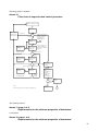
Stricter control:
The following section:
… upper control levels.
Following the inspection visit with the participation of the person in charge only one visit
demonstrating breach of ØKGa is permitted before revocation of the certificate is implemented.
The procedure for both ordinary and stricter control is shown in a flow chart in Annex 10.
Is amended:
… upper control levels.
If ØKGa is breached at the following visit, the certificate will be revoked.
5
5.
Timber windows and doors
5.1
Burglary prevention
The following section:
It must not be possible to remove a glazing unit in one piece from the outside. (This requirement is
assumed to have been met if complying with the rules in 5.9.3, paragraph 2).
Is amended:
It must not be possible to remove a glazing unit in one piece from the outside. (This requirement is
considered to have been met if the glazing unit is spot bonded to the inside of the glazing rebate).
Thermal performance
The following section:
Documentation in accordance with DS 418 or DS/EN 10077 parts 1 and 2 must be provided for
all data concerning the thermal performance of the products.
If requested by customers, the company must provide information about the window or external
door U-value and the proportion of glass in it as well as the total sunlight transmittance and solar
energy transmittance of the glazing unit in accordance with the Danish and European standards
applicable at the time, cf. for example Instruction No. 213 from The Danish Building Research
Institute ("SBi Anvisning 213").
Is amended:
Documentation in accordance with DS 418 or DS/EN 10077 parts 1 and 2 must be provided for all
data concerning the thermal performance of the products.
For each product system, documentation must be provided for a 1230x1480 mm single-light
fixed and opening casement window using the manufacturer's standard glazing unit.
For external doors, values must given for a 1230 x 2180 mm standard size panelled door with
two standard glazed lights and a mid-rail and a 1230 x 2180 mm flush door.
If requested by a customer, the company must provide information about the U-value (W/m2K)
and the proportion of glass (Aglazing unit/Awindow) of the windows and/or external doors in question
as well as the total light transmittance (LT) and solar energy transmittance (gg) of the glazing unit
in accordance with the Danish and European standards applicable at the time, cf. for example
Instruction No. 213 from The Danish Building Research Institute ("SBi Anvisning 213").
5.3
Timber material
The following section:
If there is more than one timber species in the hatched areas of illustrations in Annex 11, …
Is amended:
If there is more than one timber species in the hatched areas of illustrations in Annex 10, …
6
Spruce (European Whitewood):
The following section:
The declaration must cover at least the points mentioned in Annex 13.
Is amended:
The declaration must cover at least the points mentioned in Annex 12.
Larch:
The following section:
- The timber must conform with the specifications regarding definitions and performance
requirements listed in the table under 5.3.2 and the additional definitions and requirements listed
3
under 5.2.4. Timber density must be at least 500 kg/m at a moisture content of 12%.
…The declaration must cover at least the points mentioned in Annex 12.
Is amended:
- The timber must conform with the specifications regarding definitions and performance
requirements listed in the table under 5.3.2 and the additional definitions and requirements listed
3
under 5.2.4. The mean timber density must be at least 500 kg/m at a moisture content of 12%.
…The declaration must cover at least the points mentioned in Annex 11.
Pine (European Redwood):
The following section:
- The timber must conform with the specifications regarding definitions and performance
requirements listed in the table under 5.3.2 and the additional definitions and requirements listed
3
under 5.3.4. Timber density must be at least 500 kg/m at a moisture content of 12%. …
…Each supplier/sawmill must provide a declaration giving details of the pine used. The
declaration must cover at least the points mentioned in Annex 12.
Is amended:
- The timber must conform with the specifications regarding definitions and performance
requirements listed in the table under 5.3.2 and the additional definitions and requirements listed
3
under 5.3.4. The mean timber density must be at least 500 kg/m at a moisture content of 12%...
…Each supplier/sawmill must provide a declaration giving details of the pine used. The
declaration must cover at least the points mentioned in Annex 11.
7
Requirements for the proportion of heartwood in pine
The following section:
When using treatment systems 1 and 2 – cf. 5.5.2 – the proportion of heartwood in the hatched
areas in Annex 11 illustrations must constitute at least 60%. In laminated profiles each layer in
the hatched areas of Annex 11 illustrations must have a heartwood proportion of at least 60%.
Is amended:
When using treatment systems 1 and 2 – cf. 5.5.2 – the proportion of heartwood in the hatched
areas in Annex 10 illustrations must constitute at least 60%. In laminated profiles each layer in
the hatched areas of Annex 10 illustrations must have a heartwood proportion of at least 60%.
Inspection of heartwood proportion - treatment systems 1, 2:
The following section:
The proportion of heartwood in the hatched areas shown in Annex 11 is then recorded.
Is amended:
The proportion of heartwood in the hatched areas shown in Annex 10 is then recorded.
Inspection of heartwood proportion - treatment system 2 ØKO:
The following section:
With the exception of casement heads and frame heads, the proportion of heartwood in the
hatched areas shown in Annex 11 is recorded and the heartwood proportion and base coat
application of glazing beads checked.
Is amended:
With the exception of casement heads and frame heads, the proportion of heartwood in the
hatched areas shown in Annex 10 is recorded and the heartwood proportion and base coat
application of glazing beads checked.
5.3.4
Additional definitions and requirements for workpieces in softwood:
Cracks and checks:
The following section:
Performance requirements for cracks and checks are specified in detail in Table 5.1.2
Is amended:
Performance requirements for cracks and checks are specified in detail in Table 5.3.2
8
Laminated timber:
The following section:
Both frame and casement timbers may be glue-laminated from smaller laminates. In laminated
profiles each laminate in the hatched areas of Annex 11 illustrations must have a heartwood
proportion of at least 60%.
Is amended:
Both frame and casement timbers may be glue-laminated from smaller laminates. In laminated
profiles each laminate in the hatched areas of Annex 10 illustrations must have a heartwood
proportion of at least 60%.
Inspection and testing:
The following section:
Approved work instructions and forms for the recording of inspection and test data must be
available for all the inspection and testing activities mentioned. All data record forms must be
kept for at least 5 years and be accessible to external inspectors.
Is amended:
Approved work instructions and forms for the recording of inspection and test data must be
available for all the inspection and testing activities mentioned. All data record forms must be
kept for at least 6 years and be accessible to external inspectors.
Laminated timber:
The following section:
Both frame and casement timbers may be glue-laminated from smaller laminates. In laminated
profiles each laminate in the hatched areas of Annex 11 illustrations must have a heartwood
proportion of at least 60%.
Is amended:
Both frame and casement timbers may be glue-laminated from smaller laminates. In laminated
profiles each laminate in the hatched areas of Annex 10 illustrations must have a heartwood
proportion of at least 60%.
9
5.4.2
Design:
The following section:
By way of example, outward opening windows, hatches and doors must incorporate a sloping cill
with a slope of at least 7º. The casement bottom rail and the cill must both incorporate a drip
groove. The free gap between casement bottom rail and cill must be sufficiently large at the
exterior face to prevent droplets spanning it, min. 8 mm. Frame jamb and head and casement
jambs should incorporate water grooves.
Is amended:
By way of example, outward opening windows, hatches and doors must incorporate a sloping cill
with a slope of at least 7º. The casement bottom rail must incorporate a drip groove. The free gap
between casement bottom rail and cill must be sufficiently large at the exterior face to prevent
droplets spanning it, min. 8 mm. Frame jamb and head and casement jambs should incorporate
water grooves.
5.5
Timber preservative treatment
5.5.1
General:
The following section:
The requirements regarding surface treatment coat thickness apply to all surfaces visible when the
unit is closed. In rebates, grooves and on end grain the coat may be thinner; however, it should
always be thick enough (covered surface) for the colour of the wood not to show through. The
surface treatment must further meet the requirements listed in Annex 16 of these Regulations.
Is amended:
The requirements regarding surface treatment coat thickness apply to all surfaces visible when the
unit is closed. In rebates, grooves and on end grain the coat may be thinner; however, the surface
must be nonabsorbent. The surface treatment must further meet the requirements listed in Annex
14 of these Requirements.
5.5.2
Treatment systems for softwood:
The following section:
The surface must further meet the performance requirements listed in Annex 16 of these
Regulations.
Is amended:
The surface must further meet the performance requirements listed in Annex 14 of these
Requirements.
10
Treatment system 2:
The following section:
The surface must further meet the performance requirements listed in Annex 16 of these
Regulations.
Is amended:
The surface must further meet the performance requirements listed in Annex 14 of these
Requirements.
Treatment system 2 ØKO:
The following section:
The surface must further meet the performance requirements listed in Annex 16 of these
Regulations.
Is amended:
The surface must further meet the performance requirements listed in Annex 14 of these
Requirements.
5.5.3
Treatment systems for hardwood:
Treatment system 4: (opaque)
The following section:
The surface must further meet the performance requirements listed in Annex 16 of these
Regulations.
Is amended:
The surface must further meet the performance requirements listed in Annex 14 of these
Requirements.
11
5.8.1
Hardware:
The following section:
Hardware and screws made of materials which are not corrosion resistant and which are fitted
outside of the external face of the unit must be hot-galvanized or protected by other surface
treatment to ensure resistance to Corrosion Class 4. This can be documented by subjecting to
salt spray testing in accordance with ISO 9227 for 240 hours. Test results must be evaluated in
accordance with DS/EN/ISO 10289 and the rating achieved be at least 4.
Hardware and screws between the wet line and the external face must be made of a material or
be protected by a surface treatment which ensures resistance to Corrosion Class 3. This can be
documented by subjecting to salt spray testing in accordance with ISO 9227 for 96 hours. Test
results must be evaluated in accordance with DS/EN/ISO 10289 and the rating achieved be at
least 4.
Hardware and screws inside the wet line must be made of a material or protected by a surface
treatment which ensures resistance to Corrosion Class 2. This can be documented by salt spray
testing in accordance with ISO 9227 for 48 hours. Test results must be evaluated in accordance
with DS/EN/ISO 10289 and the rating achieved be at least 4.
Is amended:
Hardware and screws made of materials which are not corrosion resistant and which are fitted
outside of the external face of the unit must be hot-galvanized or protected by other surface
treatment to ensure resistance to Corrosion Class 4, cf. DS/EN 1670. This can be documented
by subjecting to salt spray testing in accordance with DS/EN ISO 9227 for 240 hours. Test
results must be evaluated in accordance with DS/EN ISO 10289 and the rating achieved be at
least 4.
Hardware and screws between the wet line and the external face must be made of a material or
be protected by a surface treatment which ensures resistance to Corrosion Class 3, cf. DS/EN
1670. This can be documented by subjecting to salt spray testing in accordance with DS/EN ISO
9227 for 96 hours. Test results must be evaluated in accordance with DS/EN ISO 10289 and the
rating achieved be at least 4.
Hardware and screws inside the wet line must be made of a material or protected by a surface
treatment which ensures resistance to Corrosion Class 2, cf. DS/EN 1670. This can be
documented by salt spray testing in accordance with DS/EN ISO 9227 for 48 hours. Test results
must be evaluated in accordance with DS/EN ISO 10289 and the rating achieved be at least 4.
5.8.2
Fitting:
The following section:
Hardware grooves must be adapted to the geometrical shape and thickness of the hardware.
Grooves or perforations must not cause water ingress to the wall side of frame profiles.
Is amended:
Hardware grooves must be adapted to the geometrical shape and thickness of the hardware.
When drilling or machining frame profiles, the resulting groove or hole must stop short of
penetrating the full depth of the profile to avoid water or moisture ingress to the wall side of the
profile.
12
The following section:
5.9
5.9.1
Glass and installation of glass:
Glass and panels:
Individual panes of glass must not cause visual distortion, contain defects in the glass or impurities
to a greater extent than described in DS/EN 1279 or DS 1094.0.
Unless requested otherwise by the buyer in writing, sealed glazing units must be DS certified. This
means the glazing units must have undergone impartial quality control in accordance with DS/EN
1279 or DS 1094.0 (sealed glazing units, quality control). Glazing units of foreign origin may be
used if proof of a similar quality control can be furnished.
Is amended:
5.9
5.9.1
Glass/panels and installation of glazing units:
Glass and panels:
Individual panes of glass must not cause visual distortion or contain defects or impurities in the
glass in excess of the criteria for the visual quality of sealed glazing units established by
Glasindustrien (the Danish Glass and Glazing Industry Federation).
Sealed glazing units must be manufactured to EN 1279 and the manufacturer of the units be
affiliated to an external, accredited certification scheme meeting the requirements of DS/SBC
1279 or similar special requirements.
The following section:
5.9.2
Glazing beads
With the addition of the points below, the design, ventilation, corner joints and fitting etc. of glazing
beads must comply with the fitting instructions published by Glasindustrien, see Annex 14.
Normally, the contact face of the glazing bead against the rebate must constitute at least 85% of
the height of the bead plus glazing gasket, if fitted. If present, a capillary breaking groove cannot
be deducted when calculating the contact face. The height must always be sufficient for the top
edge to be flush with casement or frame reveal while the contact face must not exceed twice the
height of the bead.
If, exceptionally, the bottom glazing bead has no projection (sliding doors etc.), ventilation holes
must be made in the rebate and the bottom of the holes have an outward slope.
In opening-casement transom and mullion windows with (multiple) glazing bars there must be no
ventilation holes in the glazing beads of the glazing bars. Ventilation around the glazing units of
such windows must be via the bottommost glazing bead or through hidden holes in the cill. Along
the sides ventilation may be ensured through a groove in the glazing rebate or openings in the
glazing bar ends where they abut the rebate. Where glazing bars cross, holes are drilled in both
directions. Grooves in side rebates must not cause water ingress at the casement head.
Other solutions may be accepted if it can be proven that there is sufficient ventilation around the
glazing unit(s).
When using glazing tapes care must be taken to cut side glazing beads to exact length as beads
which are too long will prevent correct compression of the glazing tape.
If the side glazing beads do not abut the bottom glazing bead tightly, the end grain of the side
glazing beads must be sealed and the appropriate distance between side and bottom glazing bead
be given in the drawings.
13
Glazing beads should be fixed using nails, pins and screws with surface coating or treatment
meeting the requirements for use in Corrosion Class 3.
Fixing with pins which penetrate the paint coat is permitted provided the head finishes flush with
the surface (or a fraction above). If the head finishes below the surface, the hole must be filled with
at least 1 mm of suitable material in a colour similar to the paint. The filler must provide adhesion
for a subsequent paint layer.
Pre-drilling is required if not using self-tapping screws.
Nails and pins must be at least twice as long as the thickness of the glazing bead. By using
annular ring nails or nails with similar resistance to removal glazing beads with a thickness of up to
18 mm may be fixed using 32 mm long nails.
Is amended:
5.9.2
Installation of glazing units:
Sealed glazing units may be fitted in accordance with Glasindustrien's installation instructions
applicable at the time.
Installation systems which deviate from these instructions may be applied provided they have been
approved by Glasindustrien and the glazing units are covered by the warranty scheme operated
by Glasindustrien.
Companies certified under VinduesIndustrien's Technical Requirements must be in possession of
a written agreement with the glazing unit manufacturer detailing his glazing unit installation
system(s) and containing full information about any deviation from Glasindustrien's installation
instructions.
The agreement between the window manufacturer and the glazing unit supplier must further
contain the warranty terms applicable to the glazing units supplied.
In connection with product inspection visits, defects in the installation of glazing units are rated in
accordance with Annex 8 point 5.9 while taking into account any deviating requirements under the
agreement between the window manufacturer and the glazing unit supplier.
The following section is deleted:
5.9.3
Installation of glass:
While also meeting the additional requirements below, sealed glazing units must comply fully with
the installation instructions for sealed glazing units published by Glasindustrien, see Annex 14.
If the glazing beads are located on the outside, the glazing unit must be bonded on the inside to
the internal face of the rebate in at least 4 adhesion points in order to make the window or door
burglar resistant. If it is considered necessary, glazing units with an edge length in excess of 1.2 m
must be bonded to two or more points per side at these sides.
For side hung windows and doors with glazing bars particular care should be taken to block and
support each glazing unit diagonally to transfer the total weight of the glass to the hinged casement
jamb profile.
Blocks at the lower edge of the glazing unit must have a thickness of at least 4 mm. Blocks located
elsewhere must have a thickness of at least 2 mm.
A single layer of glass may be installed using ordinary good putty shaped and cut with a putty knife
when used in connection with pins and a prior application of base coat to the rebate. If a single
layer of glass is fixed using small glazing beads (10 x 10 mm or less), these must be bonded to the
glass by means of silicone sealant or butyl tape.
Please note! In special circumstances, deviation from the description in Annex 14 may be agreed
with the glazing unit supplier but even minor deviations must be approved by him in writing.
14
6.
PVCu windows and doors
6.1
Burglary prevention:
The following section:
It must not be possible to remove a glazing unit in one piece from the outside.
(This requirement is assumed to have been met if complying with the rules in 6.8.3, paragraph 4)
Is amended:
It must not be possible to remove a glazing unit in one piece from the outside.
(This requirement is considered to have been met if the glazing unit is spot bonded to the inside of
the glazing rebate).
6.2
Thermal performance:
The following section:
If requested by customers, the company must provide information about the window or external
door U-value and the proportion of glass in it as well as the total sunlight transmittance and solar
energy transmittance of the glazing unit in accordance with the Danish and European standards
applicable at the time, cf. for example Instruction No. 213 from The Danish Building Research
Institute ("SBi Anvisning 213").
Is amended:
For each product system, documentation must be provided for a 1230x1480 mm single-light
fixed and opening casement window using the manufacturer's standard glazing unit.
For external doors, values must given for a 1230 x 2180 mm standard size panelled door with
two standard glazed lights and a mid-rail and a 1230 x 2180 mm flush door.
If requested by a customer, the company must provide information about the U-value (W/m2K)
and the proportion of glass (Aglazing unit/Awindow) of the windows and/or external doors in question
as well as the total light transmittance (LT) and solar energy transmittance (gg) of the glazing unit
in accordance with the Danish and European standards applicable at the time, cf. for example
Instruction No. 213 from The Danish Building Research Institute ("SBi Anvisning 213").
6.4.1
Finishing of profiles:
The following section:
Casement rebate measurement: Frame rebate measurement minus 2 x profile system nominal
chamber air gap ± 2 mm
Is amended:
Casement measurement:
Frame rebate measurement minus 2 x profile system nominal
chamber air gap ± 2 mm
15
6.4.2
Joints:
The following section:
At least twice a year a documented check must be carried out to ascertain that welding mirror
temperature as well as time and pressure during contact with the welding mirror agree with
instrument readings and profile supplier instructions. …
…If the manufacturer does not conduct tests as stipulated, external testing with satisfactory results
must be conducted twice a year…
…In connection with sealed glazing units the total drainage hole area must meet the requirements
stipulated in the installation instructions from Glasindustrien, the Danish Glass and Glazing
Industry Federation. Drainage holes must not be connected to cavities containing (metal)
reinforcement anywhere.
Is amended:
At each ordinary inspection visit a documented check must be carried out to ascertain that welding
mirror temperature as well as time and pressure during contact with the welding mirror agree with
instrument readings and profile supplier instructions. …
… If the manufacturer does not conduct tests as stipulated, external testing producing satisfactory
results must be conducted at each ordinary inspection visit.
… In connection with sealed glazing units the total drainage hole area must meet the requirements
stipulated in the product agreement with the glazing unit supplier. Drainage holes must not be
connected to cavities containing (metal) reinforcement anywhere.
16
6.7
Hardware and fitting of hardware:
6.7.1
Hardware:
The following section:
Hardware and screws made of materials which are not corrosion resistant and which are fitted
outside of the external face of the unit must be hot-galvanized or protected by other surface
treatment to ensure resistance meeting Corrosion Class 4. This can be documented by
subjecting to salt spray testing in accordance with ISO 9227 for 240 hours. Test results must be
evaluated in accordance with DS/EN/ISO 10289 and the rating achieved be at least 4.
Hardware and screws between the wet line and the external face must be made of a material or
be protected by a surface treatment which ensures resistance to Corrosion Class 3. This can be
documented by subjecting to salt spray testing in accordance with ISO 9227 for 96 hours. Test
results must be evaluated in accordance with DS/EN/ISO 10289 and the rating achieved be at
least 4.
Hardware and screws inside the wet line must be made of a material or protected by a surface
treatment which ensures resistance to Corrosion Class 2. This can be documented by subjecting
to salt spray testing in accordance with ISO 9227 for 48 hours. Test results must be evaluated in
accordance with DS/EN/ISO 10289 and the rating achieved be at least 4.
Is amended:
Hardware and screws made of materials which are not corrosion resistant and which are fitted
outside of the external face of the unit must be hot-galvanized or protected by other surface
treatment to ensure resistance meeting Corrosion Class 4, cf. DS/EN 1670. This can be
documented by subjecting to salt spray testing in accordance with DS/EN ISO 9227 for 240
hours. Test results must be evaluated in accordance with DS/EN/ISO 10289 and the rating
achieved be at least 4.
Hardware and screws between the wet line and the external face must be made of a material or
be protected by a surface treatment which ensures resistance to Corrosion Class 3, cf. DS/EN
1670. This can be documented by subjecting to salt spray testing in accordance with DS/EN ISO
9227 for 96 hours. Test results must be evaluated in accordance with DS/EN ISO 10289 and the
rating achieved be at least 4.
Hardware and screws inside the wet line must be made of a material or protected by a surface
treatment which ensures resistance to Corrosion Class 2, cf. DS/EN 1670. This can be
documented by subjecting to salt spray testing in accordance with DS/EN ISO 9227 for 48
hours. Test results must be evaluated in accordance with DS/EN ISO 10289 and the rating
achieved be at least 4.
6.7.2
Fitting:
The following section:
Hardware grooves must be adapted to the geometrical shape and thickness of the hardware.
Grooves or perforations must not cause water ingress to the wall side of frame profiles.
Is amended:
Hardware grooves must be adapted to the geometrical shape and thickness of the hardware.
When drilling or machining frame profiles, the resulting groove or hole must stop short of
penetrating the full depth of the profile to avoid water or moisture ingress to the wall side of the
profile.
17
The following section:
6.8
Glass and installation of glass:
6.8.1
Glass and panels:
Individual panes of glass must not cause visual distortion, contain defects in the glass or impurities
to a greater extent than described in DS/EN 1279 or DS 1094.0.
Unless requested otherwise by the buyer in writing, sealed glazing units must be DS certified. This
means the glazing units must have undergone impartial quality control in accordance with DS/EN
1279 or DS 1094.0 (sealed glazing units, quality control). Glazing units of foreign origin may be
used if proof of a similar quality control can be furnished.
Is amended:
6.8
Glass/panels and installation of glazing units:
6.8.1
Glass and panels:
Individual panes of glass must not cause visual distortion or contain defects or impurities in the
glass in excess of the criteria for the visual quality of sealed glazing units established by
Glasindustrien (the Danish Glass and Glazing Industry Federation).
Sealed glazing units must be manufactured to EN 1279 and the manufacturer of the units be
affiliated to an external, accredited certification scheme meeting the requirements of DS/SBC
1279 or similar special requirements.
The following section is deleted:
6.8.2
Glazing beads:
Glazing beads must be designed and fixed in a manner whereby glazing units and sealant
between glass and beads may be replaced without significant damage to casements or beads.
The use of glazing beads with co-extruded glazing gaskets is permitted. However, particular
care must be taken to ensure a good seal in corners when cutting to length and fitting.
In addition, the fixing of the beads must be sufficiently stable and comprehensive to maintain
compression of the sealant between glass and beads.
The length of the beads must be adapted to the longitudinal expansion of the PVCu material and
the size of the window.
18
The following section:
6.8.3
Installation of glass:
Glass must be installed using rubber or rubberlike profiles of suitable design.
The profiles and other installation materials must meet the requirements contained in the
installation instructions for sealed glazing units issued by Glasindustrien, see Annex 14.
In connection with side hung windows and doors with glazing bars particular care should be taken
to block and support each glazing unit diagonally to transfer the total weight of the glass to the
hinged casement jamb profile.
If the glazing beads are located on the outside, the glazing unit must be bonded on the inside to
the internal face of the rebate in at least 4 adhesion points in order to make the window or door
burglar resistant. If it is considered necessary, glazing units with an edge length in excess of 1.2
m must be bonded to two or more points per side at these sides.
Please note! In special circumstances, deviation from the description in Annex 14 may be agreed
with the glazing unit supplier but even minor deviations must be approved by him in writing.
Is amended:
6.8.2
Installation of glazing units:
Sealed glazing units may be fitted in accordance with Glasindustrien's installation instructions
applicable at the time.
Installation systems which deviate from these instructions may be applied provided they have been
approved by Glasindustrien and the glazing units are covered by the warranty scheme operated
by Glasindustrien.
Companies certified under VinduesIndustrien's Technical Requirements must be in possession of
a written agreement with the glazing unit manufacturer detailing his glazing unit installation
system(s) and containing full information about any deviation from Glasindustrien's installation
instructions.
The agreement between the window manufacturer and the glazing unit supplier must further
contain the warranty terms applicable to the glazing units supplied.
In connection with product inspection visits, defects in the installation of glazing units are rated in
accordance with Annex 8 point 5.9 while taking into account any deviating requirements under the
agreement between the window manufacturer and the glazing unit supplier.
19
7.
Metal windows and doors
7.1
Burglary prevention
The following section:
It must not be possible to remove a glazing unit in one piece from the outside. (This requirement is
assumed to have been met if complying with the rules in 7.8.3, paragraph 4)
Is amended:
It must not be possible to remove a glazing unit in one piece from the outside. (This requirement is
considered to have been met if the glazing unit is spot bonded to the inside of the glazing rebate).
7.2
Thermal performance:
The following section:
Documentation in accordance with DS 418 or DS/EN 10077 part 1 and 2 must be provided for all
data concerning the thermal performance of the products.
If requested by customers, the company must provide information about the window or door Uvalue and the proportion of glass in it as well as the total sunlight transmittance and solar energy
transmittance of the glazing unit in accordance with the Danish and European standards
applicable at the time, cf. for example Instruction No. 213 from The Danish Building Research
Institute ("SBi Anvisning 213").
Is amended:
Documentation in accordance with DS 418 or DS/EN 10077 part 1 and 2 must be provided for all
data concerning the thermal performance of the products.
For each product system, documentation must be provided for a 1230x1480 mm single-light
fixed and opening casement window using the manufacturer's standard glazing unit.
For external doors, values must given for a 1230 x 2180 mm standard size panelled door with
two standard glazed lights and a mid-rail and a 1230 x 2180 mm flush door.
If requested by a customer, the company must provide information about the U-value (W/m2K)
and the proportion of glass (Aglazing unit/Awindow) of the windows and/or external doors in question
as well as the total light transmittance (LT) and solar energy transmittance (gg) of the glazing unit
in accordance with the Danish and European standards applicable at the time, cf. for example
Instruction No. 213 from The Danish Building Research Institute ("SBi Anvisning 213").
20
7.4
Finishing:
7.4.1
Finishing of profiles:
The following section:
Outward opening casement corners which users may come into contact with must not be pointed
or sharp enough to be unpleasant to touch….
…Casement rebate measurement:
Frame rebate measurement minus 2 x profile
system nominal chamber air gap ± 2 mm
Is amended:
Outward opening casement corners may not be pointed or sharp enough to cause injury or
inconvenience in use or during cleaning…
…Casement measurement:
7.4.2
Frame rebate measurement minus 2 x profile
system nominal chamber air gap ± 2 mm
Joints:
The following section:
The minimum size of drainage holes is ø8 mm or a 4 x 20 mm gap; holes must be located to
ensure the removal of all water. In connection with sealed glazing units the total drainage hole area
must meet the requirements stipulated in the installation instructions from Glasindustrien, see
Annex 14.
Is amended:
The minimum size of drainage holes is ø8 mm or a 5 x 20 mm gap; holes must be located to
ensure the removal of all water. In connection with sealed glazing units the total drainage hole area
must meet the requirements stipulated in the product agreement with the glazing unit supplier.
21
7.7
Hardware and fitting of hardware:
7.7.1
Hardware:
The following section:
Hardware and screws made of materials which are not corrosion resistant and which are fitted
outside of the external face of the unit must be hot-galvanized or protected by other surface
treatment to ensure resistance to Corrosion Class 4. This can be documented by subjecting to
salt spray testing in accordance with ISO 9227 for 240 hours. Test results must be evaluated in
accordance with DS/EN/ISO 10289 and the rating achieved be at least 4.
Hardware and screws between the wet line and the external face must be made of a material or
be protected by a surface treatment which ensures resistance to Corrosion Class 3. This can be
documented by subjecting to salt spray testing in accordance with ISO 9227 for 96 hours. Test
results must be evaluated in accordance with DS/EN/ISO 10289 and the rating achieved be at
least 4.
Hardware and screws inside the wet line must be made of a material or protected by a surface
treatment which ensures resistance to Corrosion Class 2. This can be documented by subjecting
to salt spray testing in accordance with ISO 9227 for 48 hours. Test results must be evaluated in
accordance with DS/EN/ISO 10289 and the rating achieved be at least 4.
Is amended:
Hardware and screws made of materials which are not corrosion resistant and which are fitted
outside of the external face of the unit must be hot-galvanized or protected by other surface
treatment to ensure resistance to Corrosion Class 4, cf. DS/EN 1670. This can be documented
by subjecting to salt spray testing in accordance with DS/EN ISO 9227 for 240 hours. Test
results must be evaluated in accordance with DS/EN ISO 10289 and the rating achieved be at
least 4.
Hardware and screws between the wet line and the external face must be made of a material or
be protected by a surface treatment which ensures resistance to Corrosion Class 3, cf. DS/EN
1670. This can be documented by subjecting to salt spray testing in accordance with DS/EN
ISO 9227 for 96 hours. Test results must be evaluated in accordance with DS/EN ISO 10289
and the rating achieved be at least 4.
Hardware and screws inside the wet line must be made of a material or protected by a surface
treatment which ensures resistance to Corrosion Class 2, cf. DS/EN 1670. This can be
documented by subjecting to salt spray testing in accordance with DS/EN ISO 9227 for 48
hours. Test results must be evaluated in accordance with DS/EN ISO 10289 and the rating
achieved be at least 4.
7.7.2
Fitting of hardware:
The following section:
Hardware grooves must be adapted to the geometrical shape and thickness of the hardware.
Grooves or perforations must not cause water ingress to the wall side of frame profiles.
Is amended:
Hardware grooves must be adapted to the geometrical shape and thickness of the hardware.
When drilling or machining frame profiles, the resulting groove or hole must stop short of
penetrating the full depth of the profile to avoid water or moisture ingress to the wall side of the
profile.
22
The following section:
7.8
Glass and installation of glass:
7.8.1
Glass and panels:
Individual panes of glass must not cause visual distortion, contain defects in the glass or impurities
to a greater extent than described in DS/EN 1279 or DS 1094.0.
Unless requested otherwise by the buyer in writing, sealed glazing units must be DS certified. This
means the glazing units must have undergone impartial quality control in accordance with DS/EN
1279 or DS 1094.0 (sealed glazing units, quality control). Glazing units of foreign origin may be
used if proof of a similar quality control can be furnished.
Panels require the use of materials which remain stable when exposed to humidity to ensure the
panel construction remains permanently flush and tight.
Is amended:
7.8
Glass/panels and installation of glazing units:
7.8.1
Glass and panels:
Individual panes of glass must not cause visual distortion or contain defects or impurities in the
glass in excess of the criteria for the visual quality of sealed glazing units established by
Glasindustrien (the Danish Glass and Glazing Industry Federation).
Sealed glazing units must be manufactured to EN 1279 and the manufacturer of the units be
affiliated to an external, accredited certification scheme meeting the requirements of DS/SBC
1279 or similar special requirements.
Panels require the use of materials which remain stable when exposed to humidity to ensure the
panel construction remains permanently flush and tight.
23
7.8.2
Glazing beads:
The following section:
Glazing beads must be designed and fixed in a manner whereby glazing units and sealant
between glass and beads may be replaced without significant damage to casements or beads.
In addition, the fixing of the beads must be sufficiently stable and comprehensive to maintain
compression of the sealant between glass and beads.
For externally fitted glazing beads the horizontal beads must be continuous.
In principle, beads must be cut to a precise measurement but undersizes of up to 0.5 mm are
accepted.
Is amended:
Sealed glazing units may be fitted in accordance with Glasindustrien's installation instructions
applicable at the time.
Installation systems which deviate from these instructions may be applied provided they have been
approved by Glasindustrien and the glazing units are covered by the warranty scheme operated
by Glasindustrien.
Companies certified under VinduesIndustrien's Technical Requirements must be in possession of
a written agreement with the glazing unit manufacturer detailing his glazing unit installation
system(s) and containing full information about any deviation from Glasindustrien's installation
instructions.
The agreement between the window manufacturer and the glazing unit supplier must further
contain the warranty terms applicable to the glazing units supplied.
In connection with product inspection visits, defects in the installation of glazing units are rated in
accordance with Annex 8 point 5.9 while taking into account any deviating requirements under the
agreement between the window manufacturer and the glazing unit supplier.
The following section has been deleted:
7.8.3
Installation of glass:
Glass must be installed using rubber or rubberlike plastic profiles of suitable design.
The profiles and other installation materials must meet the requirements contained in the
installation instructions for sealed glazing units issued by Glasindustrien, see Annex 14.
In connection with side hung windows and doors with glazing bars particular care should be taken
to block and support each glazing unit diagonally to transfer the total weight of the glass to the
hinged casement jamb profile.
If the glazing beads are located on the outside, the glazing unit must be bonded on the inside to
the internal face of the rebate in at least 4 adhesion points in order to make the window or door
burglar resistant. If it is considered necessary, glazing units with an edge length in excess of 1.2 m
must be bonded to two or more points per side at these sides.
Please note! In special circumstances, deviation from the description in Annex 14 may be agreed
with the glazing unit supplier but even minor deviations must be approved by him in writing.
24
8.
Timber/aluminium windows and doors
8.1
Burglary prevention
The following section:
It must not be possible to remove a glazing unit in one piece from the outside. (This requirement is
assumed to have been met if complying with the rules in 8.8.3, paragraph 4)
Is amended:
It must not be possible to remove a glazing unit in one piece from the outside. (This requirement is
considered to have been met if the glazing unit is spot bonded to the inside of the glazing rebate).
8.2
Thermal performance:
The following section:
Documentation in accordance with DS 418 or DS/EN 10077 part 1 and 2 must be provided for all
data concerning the thermal performance of the products.
If requested by customers, the company must provide information about the window or external
door U-value and the proportion of glass in it as well as the total sunlight transmittance and solar
energy transmittance of the glazing unit in accordance with the Danish and European standards
applicable at the time, cf. for example Instruction No. 213 from The Danish Building Research
Institute.
Is amended:
Documentation in accordance with DS 418 or DS/EN 10077 part 1 and 2 must be provided for all
data concerning the thermal performance of the products.
For each product system, documentation must be provided for a 1230x1480 mm single-light
fixed and opening casement window using the manufacturer's standard glazing unit.
For external doors, values must given for a 1230 x 2180 mm standard size panelled door with
two standard glazed lights and a mid-rail and a 1230 x 2180 mm flush door.
If requested by a customer, the company must provide information about the U-value (W/m2K)
and the proportion of glass (Aglazing unit/Awindow) of the windows or external doors in
question as well as the total light transmittance (LT) and solar energy transmittance (gg) of the
glazing unit in accordance with the Danish and European standards applicable at the time, cf. for
example Instruction No. 213 from The Danish Building Research Institute ("SBi Anvisning 213").
25
8.3
Timber material
The following section:
If there is more than one timber species in the hatched areas of illustrations in Annex 11, the
applicable base coat and surface treatment requirement shall be the one which applies to the
species with the poorest natural durability.
Is amended:
If there is more than one timber species in the hatched areas of illustrations in Annex 10, the
applicable base coat and surface treatment requirement shall be the one which applies to the
species with the poorest natural durability.
Spruce:
The following section:
The declaration must cover at least the points mentioned in Annex 13.
Is amended:
The declaration must cover at least the points mentioned in Annex 12.
Larch:
The following section:
3
… Timber density must be at least 500 kg/m at a moisture content of 12%.
… The declaration must cover at least the points mentioned in Annex 12.
Is amended:
3
... The mean timber density must be at least 500 kg/m at a moisture content of 12%.
…The declaration must cover at least the points mentioned in Annex 11.
Pine:
The following section:
3
… Timber density must be at least 500 kg/m at a moisture content of 12%...
… The declaration must cover at least the points mentioned in Annex 12.
Is amended:
3
… The mean timber density must be at least 500 kg/m at a moisture content of 12%....
… The declaration must cover at least the points mentioned in Annex 11.
26
Requirements for the proportion of heartwood in pine
The following section:
The proportion of heartwood must constitute at least 60 % in areas outside the wet line. In
laminated profiles each laminate must have a heartwood proportion of at least 60% in areas
utside the wet line. The location of the wet line and the applicable rules/exceptions to rules are
mentioned in Annex 11.
Is amended:
The proportion of heartwood must constitute at least 60 % in areas outside the wet line. In
laminated profiles each laminate must have a heartwood proportion of at least 60% in areas
outside the wet line. The location of the wet line and the applicable rules/exceptions to rules are
mentioned in Annex 10.
Inspection of heartwood proportion - treatment systems 1, 2 and 5:
The following section:
… The proportion of heartwood in the hatched areas shown in Annex 11 is then recorded.
Is amended:
… The proportion of heartwood in the hatched areas shown in Annex 10 is then recorded.
8.3.3
Workpieces in hardwood:
The following section:
Single rooted pearl knots permitted in oak
Is amended:
Single rooted pearl knots permitted
8.3.4
Additional definitions and requirements for workpieces in softwood:
Laminated timber:
The following section:
Both frame and casement timbers may be glue-laminated from smaller laminates. In laminated
profiles each laminate in the hatched areas of Annex 11 illustrations must have a heartwood
proportion of at least 60%.
Is amended:
Both frame and casement timbers may be glue-laminated from smaller laminates. In laminated
profiles each laminate in the hatched areas of Annex 10 illustrations must have a heartwood
proportion of at least 60%.
27
The following section:
8.3.7
Type testing:
In the following cases, a type testing report from an recognized testing institution must be
provided:
- the frame rebate of the unit is manufactured wholly or partly in synthetic materials
- if hinges are fixed to synthetic material in the frame and/or casement profile
- if synthetic materials contribute to the transfer of load from casement to frame.
Testing serves the following purposes:
- to demonstrate sufficient strength and stiffness in the frame profile, primarily in terms of the
connection between timber and synthetic materials
- to demonstrate the stability and anchoring of hinges
- to demonstrate the overall stability and functioning of the unit.
Testing is conducted using a side hung, outward opening window with a width x height ratio of
900 x 1000 mm.
If the manufacturer's product range comprises windows with a width/height ratio which causes
higher loads on hinges, tests must be conducted using this size of window.
Test rig and setup
The test rig is constructed as a stable and rigid frame construction with a 910 x 1010 mm "wall
hole" or adapted to a different window size, cf. above.The unit to be tested is installed in the wall
hole with a tight fit to the test rig at the cill and at the hinge side jamb. At the hinge side, frame
screws are inserted into the timber frame rebate at the level of the hinges and screwed through
the timber section of the frame into the test rig to secure the unit to the rig.
At the handle side, the frame is blocked at fastening points and fixed at the same points using
frame screws.
Only the timber section of the frame is inside the test rig; the PVCu/aluminium section of the
frame and most of the casement are located outside the test rig opening.
Initial recording
It is checked that when closed, the frame and casement construction is completely flush.
The tightness of all screws in hinges anchored in synthetic materials is measured with a torque
screw driver and the values recorded.
The gap between casement and frame is recorded for each corner of the unit in both directions
(a total of eight measurements).
Test procedure - 90° opening
The casement is turned to 90° and secured in this position by means of a lateral guide.
A load is applied vertically to the casement head 50 mm from the outer casement corner.
The load is applied in 20 kg increments and at 3 minute intervals between each increment.
The final increment takes the total load to 80 kg which is also maintained for 3 minutes.
Recording of test results
After each load increment, any measurable movement/deformation at the junction of the frame
rebate and internal frame section is recorded. This recording must concentrate on the areas
where hinges are fitted.
3-5 minutes after relieving the load of the final load increment, any lasting deformation between
frame rebate and internal frame section is measured and recorded.
This is followed by measuring the gap between casement and frame and comparing the result
with the initial recording of values.
The tightness of screws in hinges anchored in synthetic materials is recorded.
When testing under Climatic Conditions 2 (see below), values after the final load increment are
only recorded when frame and casement materials have cooled to room temperature.
28
Test procedure - 30° opening
The casement is turned to 30° opening angle and secured in this position by means of a lateral
guide.
Then the test cycle is completed and the results recorded in accordance with the procedure
described under Test procedure - 90° opening.
Climatic Conditions
The above test procedure and recording of results must be conducted under two different
climatic conditions for both opening angles.
1. testing at room temperature (20º C)
2. testing after heating the hinge side to 65° C.
Heating to 65° C is considered complete 15 minutes after recording a temperature of 65° C of
the synthetic material where it faces the hinge.
Approval criteria
The materials and construction are approved if the following criteria have been fulfilled:
- no lasting deformation between the timber and synthetic material section of the frame
exceeding 0.5 mm
- no lasting change in the gap between casement and frame exceeding 1.0 mm at all
measuring points
- no substantial change in the tightness of screws in hinges anchored in synthetic materials.
Is amended:
8.3.7
Type testing:
In the following cases, a type testing report from a recognized testing institution must be
provided:
- if the frame rebate of the unit is manufactured wholly or partly in synthetic materials
- if hinges are fixed to synthetic material in the frame and/or casement profile
- if synthetic materials contribute to the transfer of load from casement to frame.
Testing serves the following purposes:
- to demonstrate sufficient strength and stiffness in the frame profile, primarily in terms of the
connection between timber and synthetic materials
- to demonstrate the stability and fixing of hinges
- to demonstrate the overall stability and functioning of the unit.
Testing is conducted using a side hung, outward opening window where casement width x
casement height = 700 x 700 mm.
Door units are tested using an outward opening door with a casement width and height of 950 x
2100 mm.
Test rig and setup
The test rig is constructed as a stable and rigid frame construction with a "wall hole", the width
and height of which exceeds the outer frame dimensions of the unit by 10 mm.
The unit to be tested is installed in the wall hole with a tight fit to the test rig at the cill and at the
hinge side jamb. At the hinge side, frame screws are inserted into the timber frame rebate at the
level of the hinges and screwed through the timber section of the frame into the test rig to secure
the unit to the rig.
At the handle side, the frame is blocked at fastening points and fixed at the same points using
frame screws.
29
Only the timber section of the frame is inside the test rig; the synthetic/aluminium section of the
frame and most of the casement are located outside the test rig opening.
Preload
A 400 N preload is applied vertically to the casement head 50 mm from the outer casement
corner.
The preload is applied at 90° or the max. opening angle if this is less than 90° and again at 30°.
The load is applied for one minute at both opening angles.
Initial recording
It is checked that when closed, the frame and casement construction is completely flush.
The tightness of all screws in hinges fixed to synthetic materials is measured with a torque screw
driver and the values recorded.
The starting point for each of the four individual tests to be conducted is the recording of the
following parameters:
The gap between casement and frame is recorded for each corner of the unit in both directions
(a total of eight measurements).
The geometry at the junction of the synthetic/alu frame rebate and the internal timber frame
section is recorded.
Test procedure - 90° opening
The casement/door leaf is turned to 90° or to max. opening angle if this is less than 90°; the
casement/door leaf is secured in this position by means of a lateral guide.
A load is applied vertically to the casement/door leaf head 50 mm from the outer corner of the
casement/leaf.
The load is applied in steps of 200 N with a three minute interval between each step. During the
application of the 400N load, the movements/deformations listed under Recording of test results
are measured and recorded.
Once the parameters for a load of 400 N (for doors: 600 N) have been recorded, the load is
relieved and a subsequent set of measurements taken.
Test procedure - 30° opening
The casement/door leaf is turned to 30° opening angle and secured in this position by means of
a lateral guide.
Then the test cycle is completed in accordance with the procedure described under the sections
Test procedure - 90° opening and Recording of test results below
Safety testing
The casement/door leaf is turned to 90° or to max. opening angle if this is less than 90°; the
casement/door leaf is secured in this position by means of a lateral guide.
A load of 600 N (for doors: 800 N) is applied vertically to the casement/door leaf head 50 mm
from the outer corner of the casement/door leaf.
After three minutes, the load is relieved and the same test conducted at an opening angle of 30°.
Climatic Conditions
The test procedures and recording of test results listed must be conducted under two different
climatic conditions for both opening angles.
1. Testing under laboratory conditions.
2. Testing when the hinge side has been heated to 65° C.
30
Heating to 65° C is considered complete 15 minutes after recording a temperature of 65° C of
the synthetic material where it faces the hinge.
Test sequence
The test sequence comprises a total of four individual tests and a final safety test.
The individual tests are conducted in the following sequence:
90° opening – climatic conditions 1
30° opening – climatic conditions 1
90° opening – climatic conditions 2
30° opening – climatic conditions 2
The safety test, which is the final test, is conducted at:
90° opening – climatic conditions 1
30° opening – climatic conditions 1
Recording of test results
During the application of the 400N load (for doors: 600 N), any measurable
movement/deformation at the junction of the frame rebate and internal frame section is
measured and recorded. This recording must concentrate on the areas where hinges are fitted.
3-5 minutes after relieving the 400 N load (for doors: 600 N), any lasting deformation between
the frame rebate and internal frame section is measured and recorded.
This is followed by measuring the gap between casement and frame and comparing the result
with the initial recording of values. This procedure applies to both 90° and 30° opening.
After load step 400 N (for doors: 600 N), 30° opening, climatic conditions 2 the tightness of
screws in hinges fixed to synthetic materials is recorded.
During the application of the 600 N load (for doors: 800 N) any failures in materials or
construction are recorded.
Under climatic conditions 2, the above measurements are only taken after allowing the synthetic
material at the hinge side to acclimatize for 10 minutes
Approval criteria
The materials and construction are approved if the values recorded after load step 400 meet the
following criteria:
- no lasting deformation between the timber and synthetic material section of the frame
exceeding 1,0 mm
- no lasting change in the gap between casement and frame exceeding 1,5 mm at all
measuring points
any reduction in the tightness of screws fixed in synthetic materials does not exceed 20%.
During safety testing, the final 600 N load step (for doors: 800 N) must not cause failure where
the synthetic/alu frame rebate is joined to the timber section, nor failure in hinges, their fixing or
in casement corner joints.
31
8.5
Timber preservative treatment
8.5.1
General:
The following section:
… The surface treatment must further meet the requirements listed in Annex 16 of these
Regulations.
Is amended:
… The surface treatment must further meet the requirements listed in Annex 14 of these
Requirements.
8.5.4
Treatment system for timber-aluminium units:
Treatment system 5:
The following section:
The surface must further meet the performance requirements listed in Annex 16 of these
Regulations.
Is amended:
The surface must further meet the performance requirements listed in Annex 14 of these
Requirements.
32
8.8
Hardware and fitting of hardware:
8.8.1
Hardware:
The following section:
Hardware and screws made of materials which are not corrosion resistant and which are fitted
outside of the external face of the unit must be hot-galvanized or protected by other surface
treatment to ensure resistance to Corrosion Class 4. This can be documented by subjecting to
salt spray testing in accordance with ISO 9227 for 240 hours. Test results must be evaluated in
accordance with DS/EN/ISO 10289 and the rating achieved be at least 4.
Hardware and screws between the wet line and the external face must be made of a material or
be protected by a surface treatment which ensures resistance to Corrosion Class 3. This can be
documented by subjecting to salt spray testing in accordance with ISO 9227 for 96 hours. Test
results must be evaluated in accordance with DS/EN/ISO 10289 and the rating achieved be at
least 4.
Hardware and screws inside the wet line must be made of a material or protected by a surface
treatment which ensures resistance to Corrosion Class 2. This can be documented by subjecting
to salt spray testing in accordance with ISO 9227 for 48 hours. Test results must be evaluated in
accordance with DS/EN/ISO 10289 and the rating achieved be at least 4.
Is amended:
Hardware and screws made of materials which are not corrosion resistant and which are fitted
outside of the external face of the unit must be hot-galvanized or protected by other surface
treatment to ensure resistance to Corrosion Class 4, cf. DS/EN 1670. This can be documented
by subjecting to salt spray testing in accordance with DS/EN ISO 9227 for 240 hours. Test
results must be evaluated in accordance with DS/EN ISO 10289 and the rating achieved be at
least 4.
Hardware and screws between the wet line and the external face must be made of a material or
be protected by a surface treatment which ensures resistance to Corrosion Class 3, cf. DS/EN
1670. . This can be documented by subjecting to salt spray testing in accordance with DS/EN
ISO 9227 for 96 hours. Test results must be evaluated in accordance with DS/EN ISO 10289
and the rating achieved be at least 4.
Hardware and screws inside the wet line must be made of a material or protected by a surface
treatment which ensures resistance to Corrosion Class 2, cf. DS/EN 1670. . This can be
documented by subjecting to salt spray testing in accordance with DS/EN ISO 9227 for 48
hours. Test results must be evaluated in accordance with DS/EN ISO 10289 and the rating
achieved be at least 4.
8.8.2
Fitting of hardware:
The following section:
Hardware grooves must be adapted to the geometrical shape and thickness of the hardware.
Grooves or perforations must not cause water ingress to the wall side of frame profiles.
If the fitting of a lock case etc. exceptionally requires drilling (machining) through to the glazing
rebate, the access of condensation-causing air must be prevented e.g. by taping.
Is amended:
Hardware grooves must be adapted to the geometrical shape and thickness of the hardware.
When drilling or machining frame profiles, the resulting groove or hole must stop short of
penetrating the full depth of the profile to avoid water or moisture ingress to the wall side of the
profile.
33
The following section:
8.9
Glass and installation of glass:
8.9.1
Glass and panels:
Individual panes of glass must not cause visual distortion, contain defects in the glass or impurities
to a greater extent than described in DS/EN 1279 or DS 1094.0.
Unless requested otherwise by the buyer in writing, sealed glazing units must be DS certified. This
means the glazing units must have undergone impartial quality control in accordance with DS/EN
1279 or DS 1094.0 (sealed glazing units, quality control). Glazing units of foreign origin may be
used if proof of a similar quality control can be furnished.
Panels require the use of materials which remain stable when exposed to humidity to ensure the
panel construction remains permanently flush and tight.
Is amended:
8.9
Glass/panels and installation of glazing units:
8.9.1
Glass and panels:
Individual panes of glass must not cause visual distortion or contain defects or impurities in the
glass in excess of the criteria for the visual quality of sealed glazing units established by
Glasindustrien (the Danish Glass and Glazing Industry Federation).
Sealed glazing units must be manufactured to EN 1279 and the manufacturer of the units be
affiliated to an external, accredited certification scheme meeting the requirements of DS/SBC
1279 or similar special requirements.
Panels require the use of materials which remain stable when exposed to humidity to ensure the
panel construction remains permanently flush and tight.
The following section is deleted:
8.9.2
Glazing beads:
Glazing beads must be designed and fixed in a manner whereby glazing units and sealant
between glass and beads may be replaced without significant damage to casements or beads.
In addition, the fixing of the beads must be sufficiently stable and comprehensive to maintain
compression of the sealant between glass and beads.
For externally fitted glazing beads the horizontal beads must be continuous.
In principle, beads must be cut to a precise measurement but undersizes of up to 0.5 mm are
accepted.
34
This edition has added:
8.9.2
Installation of glazing units:
Sealed glazing units may be fitted in accordance with Glasindustrien's installation instructions
applicable at the time.
Installation systems which deviate from these instructions may be applied provided they have been
approved by Glasindustrien and the glazing units are covered by the warranty scheme operated by
Glasindustrien.
Companies certified under VinduesIndustrien's Technical Requirements must be in possession of a
written agreement with the glazing unit manufacturer detailing his glazing unit installation system(s)
and containing full information about any deviation from Glasindustrien's installation instructions.
The agreement between the window manufacturer and the glazing unit supplier must further
contain the warranty terms applicable to the glazing units supplied.
In connection with product inspection visits, defects in the installation of glazing units are rated in
accordance with Annex 8 point 5.9 while taking into account any deviating requirements under the
agreement between the window manufacturer and the glazing unit supplier.
Annex 1,
Minimum requirements as regards extent of information in brochures
The following section:
4.2 Surface treatment:
5.1 Functional testing:
Opaque paint treatment (reference to Annex 16)
Yes/No (If Yes, state test method and outcome)
Is amended:
4.2 Surface treatment:
5.1 Functional testing:
EN 14351-1)
Opaque paint treatment (reference to Annex 14)
Yes/No (If Yes, state test method and class in accordance with
Annex 1,
Minimum requirements as regards extent of information in brochures
The following section is deleted:
6.1
U-value:
W/m² °C for window size 1230 x 1480 mm
Annex 8, Recording and evaluation of samples, page 3 of 24, Methods:
The following section:
… listed in Annex 15.
Is amended:
… listed in Annex 13.
35
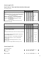
Annex 8, page 5 of 24
Specific defects: Timber and timber/aluminium (timber part)
The following section:
Description of defect
Defect category
K
V
U
5.3 and 8.3 Timber material
Pine
Missing declaration of pine rated as one defect per element
Non-compliance with heartwood proportion requirement:
See description under 5.1.4
Moisture content up to 1% above/below permitted limit
Moisture content between 1 and 2 % above/below
permitted limit
Moisture content deviating by more than 2 % from
permitted limit
The measured average width of annual ring ≥ 4 mm
B
V
Reference
Tech. Reg.
5.3, 8.3
B
U
5.3, 8.3
2.2
2.2
V
2.2
V
5.3.3, 8.3.3
Is added and amended:
Description of defect
Defect category
K
V
U
Reference
B
Tech. Reg.
5.1 and 8.1 Burglary prevention
No bonding to inside of glazing rebate
V
5.1
V
5.3, 8.3
5.3 and 8.3 Timber material
Pine
Missing declaration of pine rated as one defect per element
Non-compliance with heartwood proportion requirement:
See description under 5.3
5.3, 8.3
Moisture content up to 1% above/below permitted limit
B
Moisture content between 1 and 2 % above/below
permitted limit
U
2.2
2.2
Moisture content deviating by more than 2 % from
permitted limit
V
2.2
The measured average width of annual ring > 4 mm
V
5.3, 8.3
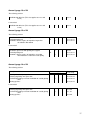
Annex 8, page 6 of 24
The following section:
Resin exudation
B
Annex 15
B
Annex 14
Is amended:
Resin exudation
36
Annex 8, page 10 of 24
The following section:
Not filled with adhesive (This also applies to 5.5.3. and
8.5.4.)
V
5.6.2
V
5.6.2
V
5.9.1, 8.9.1
5.9.1, 8.9.1
Is amended:
Not filled with adhesive (This also applies to 5.6.3. and
8.4.4.)
Annex 8, page 12 of 24
The following section:
5.9 Glass and installation of glass
Cracked glazing unit
Distortion, defects in glass or impurities larger than
described in DS 1094.0
K
Is amended:
5.9 Glass and installation of glass
No written agreement with glazing unit supplier
Cracked glazing unit
Distortion, defects in glass or impurities exceeding
Glasindustrien's criteria for visual quality
V
5.9.2
5.9.1, 8.9.1
5.9.1, 8.9.1
K
V
Annex 8, page 14 of 24
The following section:
Description of defect
Blocking of sealed glazing units:
Covering of glazing unit spacer bar:
Insufficiently burglary-resistant installation of sealed glazing
units
Glazing gaskets:
Defect category
K
V
U
V
B
Reference
Tech. Reg.
5.9.3, 8.9.3
5.9.3, 8.9.3
5.9.3, 8.9.3
5.9.3, 8.9.3
Is amended:
Blocking of sealed glazing units:
Covering of glazing unit spacer bar:
Insufficiently burglary-resistant installation of sealed glazing
units
Glazing gaskets:
V
5.9, 8.9
5.9, 8.9
5.1, 8.1
5.9, 8.9
37
Annex 8, page 14 of 24
The following section:
No sealing between timber and aluminium at casement
head
V
8.4.5
V
8.4.3
Is amended:
No sealing between timber and aluminium at casement
head
Annex 8, page 15 of 24
The following section:
Description of defect
Defect category
K
V
U
ReferenB
Tech. eg.
6.3 Profile material
Is added:
Specific defects: PVCu
Defect categories: K = critical, V = significant, U = immaterial, B = comment
Description of defect
Referen-
Defect category
K
V
U
B
Tech. eg.
6.1 Burglary prevention
No bonding to inside of glazing rebate
V
6.1
6.3 Profile material
Annex 8, page 17 of 24
The following section:
6.8 Glass and installation of glass
Cracked glazing unit
Distortion, defects in glass or impurities larger than
described in DS 1094.0
K
6.8.1
Is amended:
6.8 Glass/panels and installation of glazing units
No written agreement with glazing unit supplier
Cracked glazing unit
Distortion, defects in glass or impurities exceeding
Glasindustrien's criteria for visual quality
V
K
V
6.8.2
6.8.1
6.8.1
38
Annex 8, page 19 of 24
The following section:
Description of defect
Defect category
K
V
U
B
Reference
Tech. Reg.
7.3 and 8.3.5 Profile material and aluminium material
Is added:
Description of defect
Reference
Defect category
K
V
U
B
Tech. Reg.
7.1 and 8.1 Burglary prevention
No bonding to inside of glazing rebate
V
7.1, 8.1
7.3 and 8.3.5 Profile material and aluminium material
Annex 8, page 20 of 24
The following section:
7.5 Surface treatment
Average layer thickness on coated surface of individual
item below 40 µm
Average layer thickness on coated surface of entire sample
falls outside of 50-120 µm (recorded as 1
defect for the entire sample)
Average layer thickness on anodized surface below 16 µm
(recorded as 1 defect for the entire sample)
V
7.5.1, 8.6.1
U
7.5.1, 8.6.1
U
7.5.2, 8.6.2
Is amended:
7.5 Surface treatment
Average layer thickness on coated surface of individual
item below 40 µm for wet application of paint
and 50 µm for powder coating
Average layer thickness on coated surface of entire sample
falls outside of 50-120 µm for powder coating
and 40 -70 µm for wet application of paint
(recorded as 1 defect for the entire sample)
Average layer thickness on anodized surface below 16 µm
(recorded as 1 defect for the entire sample)
V
7.5.1, 8.6.1
V
7.5.1, 8.6.1
V
7.5.2, 8.6.2
39
Annex 8, page 23 of 24
The following section:
7.8 Glass and installation of glass
Cracked glazing unit
Distortion, defects in glass or impurities larger than
described in DS 1094.0
No certificate on sealed glazing units
Glazing unit not cleaned
K
7.8.1, 8.9.1
V
V
7.8.1, 8.9.1
7.8.1, 8.9.1
7.8.1, 8.9.1
U
Is amended:
7.8 Glass and installation of glass
No written agreement with glazing unit supplier
Cracked glazing unit
Distortion, defects in glass or impurities exceeding
Glasindustrien's criteria for visual quality
V
7.8.2
7.8.1, 8.9.1
V
7.8.1, 8.9.1
K
Annex 8, page 24 of 24
The following section:
Description of defect
Defect category
K
V
U
B
Reference
Tech. Reg.
7.8.3, 8.9.3
Defect category
K
V
U
B
Reference
Tech. Reg.
7.8, 8.9
Glazing gaskets:
Is amended:
Description of defect
Glazing gaskets:
40
Following section is deleted:
Annex 10,
Flow chart of inspection and control procedure
Selection for inspection visit
A
Inspection visit
Result recorded.
A approved
Statistics posted
at end of round
A Rejected because the
number of significant
defects is twice the
upper limit for
significant defects
A rejected
B
Stricter control
first visit
Report to person
in charge at end
of round
C
Stricter control
second visit
1
If C is conducted as a
result of starting via 1,
C must meet criteria for
approval
B and C rejected
B and C approved
B or C
rejected
Report to person
in charge at end
of round
D
Stricter control
third visit
C and D
rejected
C and D approved
B and D approved,
Report to person
in charge at end
of round
D and E approved
Immediate
report to person
in charge
but C rejected
E
Stricter control
fourth visit
D and E or
C and E
rejected
Additional
inspection visit
with
participation of
person in
charge within
30 days of
previous visit
Approved
Stricter
control
Rejected
Note:
Certificate
revoked
1
1
Person in charge = person in charge at certifying body
The following section:
Annex 11, page 1 of 6,
Requirements for the minimum proportion of heartwood
Is amended:
Annex 10, page 1 of 6,
Requirements for the minimum proportion of heartwood
41
The following section:
Annex 12,
Paradigm for the declaration of pine (European Redwood) /larch
-
that the heartwood diameter of the log at the top end exceeded 50% of the
top diameter
-
That planks * and boards have been sawn from a butt log with a top diameter
in excess of 200 mm or the following log (log no. 2) with a top diameter in
excess of 170 mm
-
that the log has been handled and stored in a way so as not to incur risk of
bacterial attack
-
that 60% of the planks have a heartwood proportion in excess of 60%
-
that the heartwood proportion in the remaining planks is in excess of 40%
-
that the moisture content is 12 ± 2% for joinery and 18 ± 4% when dry for
dispatching
**
**
**
-
that the width of the annual rings is less than 4 mm
-
that the density is above 500 kg/m³ (12 ±2% moisture)
*)
**)
**
that the wood has not been treated with a chemical preservative
Planks are defined as all dimensions with a thickness in excess of 48 mm
Sampling (sample size) in accordance with Svensk Standard (Swedish Standard) SS 232740
Is amended:
Annex 11,
Paradigm for the declaration of pine (European Redwood) /larch
-
that the heartwood diameter of the log at the top end exceeded 50% of the
top diameter
-
That planks and boards have been sawn from a butt log with a top diameter in
excess of 200 mm or the following log (log no. 2) with a top diameter in
excess of 170 mm …………….
-
that the log has been handled and stored in a way so as not to incur risk of
bacterial attack
-
that 60% of the planks have a heartwood proportion in excess of 60%
……………………..
-
that the heartwood proportion in the remaining planks is in excess of 40%
………………...
**
that the moisture content is 12 ± 2% for joinery and 18 ± 4% when dry for
dispatching……
***
*
**
**
-
that the width of the annual rings is less than 4 mm
-
that the density is above 500 kg/m³ (12 ±2%
moisture)…………………………………….
that the wood has not been treated with a chemical preservative
*)
Planks are defined as all dimensions with a thickness in excess of 48 mm
**)
Sampling (sample size) in accordance with Svensk Standard (Swedish Standard) SS 232740
***) When documenting density it is recommended to indicate the weight and volume on each pack
42
The following section:
Annex 13,
Paradigm for the declaration of spruce (European Whitewood)
Is amended:
Annex 12,
Paradigm for the declaration of spruce (European Whitewood)
Following section is deleted:
Annex 14, page 1 of 4,
Monteringsanvisning Grundlag for garantiordningen
Requirements for the checking and accuracy of measuring equipment
The following section:
Annex 15,
Requirements for the checking and accuracy of measuring equipment
Is amended:
Annex 13,
Requirements for the checking and accuracy of measuring equipment
The following section:
Annex 16,
Expected outcome of industrial surface treatment of timber elements
Is amended:
Annex 14,
Expected outcome of industrial surface treatment of timber elements
The following section:
Annex 17, page 1 of 2,
Standards at a glance
Is amended:
Annex 15, page 1 of 2,
Standards at a glance
The following section:
43
Annex 18,
Technical Regulations - current and previous editions
…6th edition - May 2005
6th Edition, Rev. 1 - July 2005
6th Edition, Rev. 2 - May 2006
6th Edition, Rev. 3 - October 2006
Is amended:
Annex 16,
Technical Regulations - current and previous editions
…6th edition - May 2005
6th Edition, Rev. 1 - July 2005
6th Edition, Rev. 2 - May 2006
6th Edition, Rev. 3 - December 2006
7th Edition - January 2008
44