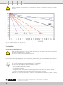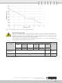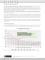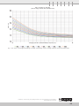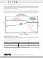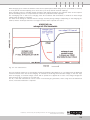
1
Installation, commissioning and operating instructions Similar to the illustration, AquaGen® optional for vented stationary lead-acid batteries Installation, commissioning and operating instructions for vented stationary lead-acid batteries Type, Design, Print: Koerdt Promo4you GmbH, 59929 Brilon © 2013 HOPPECKE Batterien GmbH & Co. KG P.O. Box 1140 D-59914 Brilon All rights reserved, even for patent and utility patent applications. The distribution and duplication of this document and the use and disclosure of its contents are prohibited unless written permission is granted by HOPPECKE Batterien GmbH & Co. KG. Noncompliance will result in a claim for damages. Installation, commissioning and operating instructions for vented stationary lead-acid batteries 7140203152 V1.2 (09.2015) 2 Preface Valued customer, Thank you for choosing a HOPPECKE product. Please read this documentation carefully and completely before performing any tasks using the lead-acid batteries. This documentation contains important information regarding safe and correct unpacking, storage, installation commissioning, operation and maintenance of lead-acid batteries. Non-compliance with these safety instructions can lead to severe personal injury and material damage. HOPPECKE is not responsible or liable for direct or indirect injury or damage resulting from improper use of this product; all warranty claims become null and void. HOPPECKE reserves the right to make changes to the contents of this documentation. HOPPECKE Batterien GmbH & Co. KG is not responsible for errors in this documentation. HOPPECKE is not liable for direct damage related to the use of this documentation. Our products are undergoing constant development. For this reason, there may be discrepancies between the product that you have purchased and the product as represented in this documentation. Please keep this documentation so that it is immediately available for all personnel who must perform work in connection with the batteries. If you have questions, we would be happy to help you. You can reach us via e-mail [email protected] or by phone on working days between the hours of 8 am and 4 pm (CET) at the following number Phone +49(0)2963 61-0 Fax +49(0)2963 61-481 Your team from HOPPECKE Batterien GmbH & Co. KG Postal address: HOPPECKE Batterien GmbH & Co. KG P.O. Box 1140 D-59914 Brilon Germany Head office address: HOPPECKE Batterien GmbH & Co. KG Bontkirchener Straße 1 D–59929 Brilon-Hoppecke Phone +49 (0)2963 61-0 Fax +49 (0)2963 61-449 Internetwww.hoppecke.com [email protected] Installation, commissioning and operating instructions for vented stationary lead-acid batteries 7140203152 V1.2 (09.2015) 3 Used Symbols The following safety notes need to be observed. Listed symbols are used multiple times for safety relevant information: Personal health, batteries or the environment are at risk. Failure to observe this hazard notice can lead to severe or fatal injury. Danger! Batteries, materials or the environment are at risk. Personal safety is not at risk. Failure to observe this notice can lead to malfunction or damage to the batteries. In addition, material and environmental damage may occur. Attention! Risk of explosion or blast, splashing of hot or molten substances. Explosion and fire hazard, avoid short circuits! Avoid electrostatic charge and discharge/sparks. Failure to observe this hazard notice can lead to severe or fatal injury. Risk of corrosion caused by leaking electrolyte. Electrolyte is strongly corrosive. Electrical voltages hazardous to health may cause fatal injury. Metal parts of the battery are always alive, therefore do not place items or tools on the battery. Failure to observe this hazard notice can lead to severe or fatal injury. Warning! Risks caused by batteries. Do not smoke! Do not use any naked flame or other sources of ignition. Risk of explosion and fire! General prohibition Observe these instructions and keep them located near the battery for future reference. Work on batteries only after instruction by qualified personnel. Wear protective goggles and clothing while working on batteries. Observe the accident prevention rules as well as EN 50272-2 und EN 50110-1. Wear conductive shoes. General order Installation, commissioning and operating instructions for vented stationary lead-acid batteries 7140203152 V1.2 (09.2015) 4 Any acid splashes on the skin or in the eyes must be rinsed with plenty of clean water immediately. Then seek medical assistance. Spillages on clothing should be rinsed out with water! Recycling Spent batteries have to be collected and recycled separately from normal household wastes. Pb General notice or tip for better understanding and optimum use of the battery or batteries. 0 Safety notices 0.1 General Information Incorrect use of the products described here can lead to personal and material damage. HOPPECKE is not responsible or liable for direct or indirect personal and material damages which occur as a result of handling the products described here. Danger! Risk of explosion and fire, avoid short circuits. Attention! Metal parts of the battery or batteries are always live, so never place foreign objects or tools on top of the batteries. Electrostatic discharges can ignite oxyhydrogen gas and therefore cause an explosion of the battery! Exploding parts can lead to heavy injuries. Electrolyte is highly corrosive. In normal operation, it is not possible to come into contact with electrolyte. If the battery casing is destroyed, leaked bonded electrolyte is just as corrosive as liquid electrolyte.. Leaking electrolyte is harmful to the eyes and skin. Refer also to chap. 2.3, Safety precautions! Incomplete or insufficient maintenance can lead to unexpected battery failure or reduction of battery power. Maintenance work must be completed once every six months by authorized technical specialists in accordance with the instructions in this documentation. Attention! Danger! Work on batteries, especially installation and maintenance should be performed by trained HOPPECKE specialists (or by personnel authorized by HOPPECKE) only; personnel must be familiar with battery handling and the required precautionary measures. Unauthorized persons must keep away from the batteries! Without proper and regular maintenance of the batteries by HOPPECKE specialists (or personnel authorized by HOPPECKE), the safety and reliability of the power supply during operation cannot be ensured. Installation, commissioning and operating instructions for vented stationary lead-acid batteries 7140203152 V1.2 (09.2015) 5 HOPPECKE offers the following type ranges as vented lead-acid (VLA) batteries: GroE OSP.HC OSP.XC OPzS OPzS solar.power max.power power.bloc OPzS OPzS bloc solar.power OGi bloc OGi bloc HC USV bloc Following symbols and pictograms are pictured on each battery cell or on each battery block: Read the instruction for installation, commissioning and operation carefully. Always wear protective goggles and cloths. Avoid naked flames and sparks. General danger warning. Risk of electrical voltage. Risk of chemical burns through electrolyte. Risk of explosion, avoid short circuits, electrostatic charge and discharge/sparks. Battery with low concentration of antimony. Used batteries with this symbol have to be recycled. Used batteries which are not sent for recycling are to be disposed of as special waste under all relevant regulations. Pb Installation, commissioning and operating instructions for vented stationary lead-acid batteries 7140203152 V1.2 (09.2015) 6 0.2 Safety instructions for working with lead-acid batteries working with lead-acid batteries When working on batteries, always observe the safety regulations documented in DIN EN 50110-1 (VDE 0105-1) Operation of electrical installations: • Always proceed in the correct order when installing and removing the battery and when connecting it to the charger. • Pay attention to the polarity! • Make sure the connections are tight. • Use only battery charger leads that are in perfect technical condition and that have adequate cross-sections. • Batteries must not be connected or disconnected while current is flowing or while the charger is switched on. • Before opening the load circuit, make sure that the charger is in a switched-off state by measuring the voltage. • Secure the charger to prevent it from being switched back on again! • Heed the instructions given in the operating manual provided by the manufacturer of the battery charger. Danger! Under certain conditions, there is a risk caused by electrical battery voltage and in the event of a short circuit, extremely high short circuit currents may flow. There is a risk of explosion and fire due to explosive gas. Observe the following regulations (IEEE standards valid for USA only): – ZVEI publication “Instructions for the safe handling of electrolyte for lead-acid accumulators.” – VDE 0510 Part 2: 2001-12, in accordance with EN 50272-2:2001: “Safety requirements for secondary batteries and battery installations - Part 2: Stationary batteries”. – DIN EN 50110–1 (VDE 0105–1): Operation of electrical installations; German version EN 50110-1:2004. – IEEE Standard 485–1997: “Recommended Practice for Sizing Large Lead Acid Storage Batteries for Generating Stations.” – IEEE Standard 1187–2002: “Recommended Practice for Installation Design and Installation of Valve Regulated Lead-Acid Storage Batteries for Stationary Applications”. – IEEE Standard 1188–2005: “Recommended Practice for Maintenance, Testing and Replacement of Valve Regulated Lead-Acid (VRLA) Batteries for Stationary Applications”. – IEEE Standard 1189–2007: “Guide for Selection of Valve-Regulated Lead-Acid (VRLA) Batteries for Stationary Applications”. – IEEE Standard 1375–1998: “Guide for Protection of Stationary Battery Systems”. Batteries contain corrosive acids which can lead to chemical burn on skin and eyes if the battery is damaged! You must wear safety goggles while handling the battery! Wear all the intended personal safety clothing while handling the batteries! Installation, commissioning and operating instructions for vented stationary lead-acid batteries 7140203152 V1.2 (09.2015) 7 1. When renewing old batteries, ensure that all electrical loads are switched off before removing the old battery (separators, fuses, switches). This must be carried out by qualified personnel. 2. R emove all wrist watches, rings, chains, jewelry and other metal objects before working with batteries. Danger! 3. Use insulated tools only. 4. Wear insulating gloves and protective shoes (refer to also to Chap. 2.2). 5. Never place tools or metal components on top of the batteries! Danger! Danger! 6. M ake sure that the battery or batteries are not mistakenly grounded. If the system is grounded, terminate the connection. Touching a grounded battery by mistake can result in severe electric shock. The risk caused by an incorrect connection can be significantly reduced by terminating the ground connection. 7. B efore establishing connections, make sure to check the correct polarity - better one too many times than one too few. Attention! 8. F illed lead-acid batteries contain highly explosive gas (hydrogen/air mixture). Never smoke, handle open flames or create sparks near the batteries. Always avoid electrostatic discharge; wear cotton clothing and ground yourself if necessary. Danger! 9. Use only suitable hoisting devices with sufficient carrying capacity. 10. Never carry batteries by the battery terminals. Danger! Attention! 11. T hese batteries contain lead and cannot under any circumstances be disposed of with household waste or at a waste dump at the end of their service life (for more information, refer to Chap. 1.4). Installation, commissioning and operating instructions for vented stationary lead-acid batteries 7140203152 V1.2 (09.2015) 8 Table of contents Preface.................................................................................................................................................... 3 Used Symbols.......................................................................................................................................... 4 0 Safety notices...................................................................................................................................... 5 0.1 General information................................................................................................................... 5 0.2 Safety instructions for working with lead-acid batteries................................................................ 7 1 General information............................................................................................................................. 11 1.1 Safety precautions................................................................................................................... 11 1.2 Technical Data........................................................................................................................ 11 1.2.1 Example for single cell............................................................................................................. 11 1.2.2 Identification plate battery........................................................................................................ 12 1.3 CE-Mark.................................................................................................................................. 12 1.4 Disposal and recycling.............................................................................................................. 12 1.5 Service.................................................................................................................................... 12 2 Safety................................................................................................................................................. 13 2.1 General................................................................................................................................... 13 2.2 Personal safety equipment, protective clothing, equipment......................................................... 14 2.3 Safety precautions................................................................................................................... 14 2.3.1 Sulfuric acid............................................................................................................................ 14 2.3.2 Explosive gases....................................................................................................................... 15 2.3.3 Electrostatic discharge............................................................................................................. 15 2.3.4 Electric shock and burns.......................................................................................................... 16 3 Transport............................................................................................................................................ 18 3.1 General................................................................................................................................... 18 3.2 Delivery completeness and externally visible damage................................................................ 18 3.3 Defects................................................................................................................................... 18 4 Storage.............................................................................................................................................. 19 4.1 General.................................................................................................................................. 19 4.2 Storage time........................................................................................................................... 19 4.3 Preparing for a several-months storage period.......................................................................... 19 5 Installation ....................................................................................................................................... 20 5.1 Demands on the erection site................................................................................................... 20 5.1.1 Calculation of safety distance................................................................................................... 22 5.2 Filling the cells......................................................................................................................... 23 5.2.1 Check..................................................................................................................................... 23 5.2.1.1Ventilation – preventing explosions........................................................................................... 23 5.2.1.2Ventilation – calculation for ventilation requirements of battery rooms......................................... 24 5.2.2 Filling the cells......................................................................................................................... 25 5.2.3 Idle Time................................................................................................................................. 25 5.3 Conducting an open-circuit voltage measurement....................................................................... 26 5.4 Installation tools and equipment............................................................................................... 26 5.5 Rack Installation...................................................................................................................... 27 5.6 Cabinet installation.................................................................................................................. 28 5.7 Handling the batteries.............................................................................................................. 28 5.8 General information on connecting the batteries........................................................................ 29 5.9 Putting the cells/blocks into the racks...................................................................................... 29 5.10 Connecting the batteries.......................................................................................................... 31 5.10.1 Connection terminals............................................................................................................... 31 5.10.2 Type of connection cable.......................................................................................................... 31 5.10.3 Clamping batteries using battery connectors.............................................................................. 32 5.10.4 Installing the screwed connectors............................................................................................. 32 5.10.5 Clamping connection plates onto the batteries.......................................................................... 33 Installation, commissioning and operating instructions for vented stationary lead-acid batteries 7140203152 V1.2 (09.2015) 9 5.11 Connect the battery system to the DC power supply................................................................... 33 5.12 Commissioning charge (initial charge)....................................................................................... 34 5.12.1 Commissioning charge with constant voltage (IU characteristic curve)......................................... 34 5.12.2Commissioning charge with constant current (I characteristic curve) or decreasing current (W characteristic curve)............................................................................................................ 35 5.12.3 Extended commissioning charge............................................................................................... 35 5.13 Electrolyte level check.............................................................................................................. 35 5.14 Electrolyte density adjustment.................................................................................................. 35 6 Battery operation................................................................................................................................ 36 6.1 Discharging............................................................................................................................. 36 6.2 Charging – general................................................................................................................... 36 6.2.1 Standby parallel operation........................................................................................................ 38 6.2.2 Floating operation.................................................................................................................... 39 6.2.3 Switch mode operation (charge/discharge operation)................................................................. 39 6.2.4 Float charging.......................................................................................................................... 40 6.2.5 Equalizing charge (correction charge)......................................................................................... 40 7 Settings for charging HOPPECKE OPzS solar.power batteries............................................................... 41 7.1 General charging characteristic................................................................................................. 41 7.2 General hints for battery charging in solar or off-grid applications................................................ 41 7.3 Standard charge procedures..................................................................................................... 42 7.4 Equalizing charge..................................................................................................................... 42 7.5 Charging procedure for cyclic applications.................................................................................. 43 7.6 Charging currents..................................................................................................................... 44 7.7 Alternating currents.................................................................................................................. 44 7.8 Water consumption.................................................................................................................. 44 7.9 Temperature influence on battery performance and lifetime........................................................ 45 7.9.1 Temperature influence on battery capacity................................................................................. 45 7.9.2 Temperature influence on battery lifetime.................................................................................. 45 7.10 Influence of cycling on battery behavior..................................................................................... 46 7.10.1 Cycle life time depending on depth of discharge (DoD)............................................................... 46 7.10.2 Cycle life time depending on ambient temperature..................................................................... 46 7.10.3 Electrolyte freezing point depending on depth of discharge (DoD)................................................ 47 7.11 Remarks to warranty management............................................................................................ 48 7.12 Recharge-time diagrams........................................................................................................... 48 8 Battery maintenance........................................................................................................................... 50 8.1 Work to be performed every six months..................................................................................... 50 8.2 Work to be performed annually................................................................................................. 50 8.3 Cleaning of batteries................................................................................................................ 50 9 Testing the battery system.................................................................................................................. 51 9.1 Performing the capacity test (short form)................................................................................... 51 9.2 Performing the capacity test (extended version)......................................................................... 52 9.3 Capacity test of the battery....................................................................................................... 54 10 Troubleshooting................................................................................................................................. 56 11 Required ventilation for hydrogen generated by batteries................................................................... 56 Inspection protocol................................................................................................................................. 58 Safety data sheet................................................................................................................................... 59 Installation, commissioning and operating instructions for vented stationary lead-acid batteries 7140203152 V1.2 (09.2015) 10 1 General information Vented lead-acid batteries contain liquid electrolyte. Due to the electro chemical potential oxyhydrogen gas is continuously generated. Decomposed water needs to be refilled from time to time. Using the HOPPECKE AquaGen recombination system (optional accessory) can drastically extend water refilling intervals. Due to the liquid electrolyte, vented lead-acid batteries can only be operated in upright position. The HOPPECKE product range comprises several vented lead acid batteries like single cells (nominal voltage 2 V) or blocs (nominal voltage of: 6 V or 12 V) for different applications. For example: GroE, OSP.HC, OSP.XC, OPzS, OPzS solar.power, OGi bloc, OGi bloc HC, power.bloc OPzS und OPzS bloc solar.power. 1.1 Safety precautions Danger! Danger! Read this documentation carefully and completely before performing any tasks using the batteries. This documentation contains important information regarding the safe and correct unpacking, storage, installation commissioning, operation and maintenance of filled lead-acid batteries. To ensure your own safety as well as the safety of your colleagues and the system, it is essential that you have read and understood all instructions in this documentation and adhere to them strictly. If you have not understood the information contained in this documentation or if local regulations and conditions apply which are not covered by the documentation (or run contrary to the information in this documentation), please contact your local HOPPECKE representative. You can also contact us at our head office directly. If you are conducting any work on or with the battery system, it is essential that you familiarize yourself with the installation, operation and maintenance of lead-acid batteries. Attention! 1.2 Technical Data 1.2.1 Example for single cell Each battery cell or bloc contains an identification plate on top of the cell/bloc lid. Refer to the example below. 5 OPzS 250 2V 250Ah CN / 266 Ah C10 Ufloat = 2.23 V/cell d20°C/68°F = 1.24 kg/l Made in Germany Example: The information on the identification plate is as follows: 5 OPzS 250 5 = number of positive plates OPzS = battery type 250 = nominal capacity C10 (capacity during discharge with ten hours’ current (I10) over a discharge time of 10 h (t10). 266 = actual capacity C10 (capacity of discharges with 10 h current) Installation, commissioning and operating instructions for vented stationary lead-acid batteries 7140203152 V1.2 (09.2015) 11 1.2.2 Identification plate battery The identification plate of the entire battery system can be found on the battery rack or inside the battery cabinet. The nominal voltage, the number of cells/blocks, the nominal capacity (C10 = CN) and the battery type are listed on the identification plate of the system. Fig. 1–1: Example for type plate on battery rack 1.3 CE-Mark Effective as of 1 January 1997, the EC declaration of conformity 2006/95/EC (Low Voltage Directive) and the corresponding CE marking for the battery system are required for batteries with a nominal voltage between 75 V and 1500 V DC. The installer of the battery system is responsible for displaying the declaration and affixing the CE label on or next to the battery’s identification plate. 1.4 Disposal and recycling Used batteries with this marking are recyclable goods and must be sent for recycling. Attention! Pb Used batteries which are not sent for recycling are to be disposed of as special waste under all relevant regulations. We offer our customers our own battery return system. All lead acid batteries are taken to the secondary lead smelting plant at our HOPPECKE site, observing the provisions of the German – recycling and waste law – battery regulations – transport approval regulations – together with the general principles of environmental protection and our own corporate guidelines. The HOPPECKE smelting plant is the only lead smelter in Europe certified under: – DIN EN ISO 9001 (processes and procedures), – DIN EN ISO 14001 (environmental audit), – and specialist disposal regulations covering specialist disposal with all associated waste codes for storage, treatment and recycling. For further information: +49 (0)2963 61-280. 1.5 Service HOPPECKE has a worldwide service network that you should take advantage of. HOPPECKE service is there for you whenever you need specialist consultation for installation of the battery system, parts and accessories or system maintenance. Contact us or your local HOPPECKE representative. HOPPECKE service: Email: [email protected] Refer to the HOPPECKE website for contact data of all international HOPPECKE branches: Internet: www.hoppecke.com Installation, commissioning and operating instructions for vented stationary lead-acid batteries 7140203152 V1.2 (09.2015) 12 2 Safety 2.1 General If the container of a filled lead-acid battery is damaged, electrolyte, acid mist or hydrogen gas may escape. Always take the normal safety precautions when working with lead-acid batteries. Procedure for handling acid spills: Fix acid using a binding material such as sand and neutralize it using calcium carbonate, sodium carbonate or sodium hydroxide. Dispose of the acid according to the official, local regulations. Do not allow acid to escape into the sewage system, soil or water. The following table contains a list of chemicals recommended for neutralizing electrolyte in an approved system. Observe the safety measures, even when neutralizing small amounts of electrolyte. Danger! Mix the required quantities of the chemicals (see Tab. 2–1) with the electrolyte in small portions. Take special care when adding sodium carbonate, as this results in intense foaming. Danger! Neutralization is complete when a pH value between 6 and 8 has been reached. If there is no suitable measuring device available, the degree of neutralization can be checked using common pH paper. Neutralization is complete when the pH paper turns olive green to yellow in color. If the pH paper is blue, this indicates that the neutralization point has been exceeded. Acid must be added to neutralize the mixture again. Gel electrolyte from damaged or used batteries can be disposed of in the same way. The following quantities of any these chemicals can be used to neutralize 1 liter of electrolyte with the listed nominal density: Sodium hydroxide (I) Nominal density Calcium carbonate (kg) CaO Sodium carbonate (kg) Na2CO3 NaOh 20% concentration 1.20 kg/l 0.19 0.36 1.36 0.6 1.24 kg/l 0.23 0.44 1.65 0.73 1.27 kg/l 0.26 0.5 1.88 0.83 1.29 kg/l 0.28 0.54 2.03 0.9 NaOH 45% concentration Tab. 2–1: Chemicals for neutralizing 1 liter of electrolyte Observe all regulations, documentation and standards as described in Chap. 0.2. Installation, commissioning and operating instructions for vented stationary lead-acid batteries 7140203152 V1.2 (09.2015) 13 2.2 Personal safety equipment, protective clothing, equipment If working with lead-acid batteries, the following equipment must be provided at the very least: – Insulated tools – Rubber gloves – Protective shoes – Fire extinguisher – Rubber apron – Protective goggles – Face shield – Face mask – Emergency eye wash. To avoid electrostatic charging, all textiles, protective shoes and gloves worn while working with batteries must have a surface resistance of <108 ohm and an insulation resistance of ≥105 ohm (refer EN 50272-2 and DIN EN ISO 20345:2011 Personal protective equipment - Safety footwear). If possible wear ESD shoes. Danger! Remove all wrist watches, rings, chains, jewelry and other metal objects before working with batteries. Never smoke, handle open flames or create sparks near the batteries. Never place tools or metal components on top of the batteries. The use of proper tools and safety equipment can help to prevent injury or reduce the severity of injury in case of an accident. 2.3 Safety precautions 2.3.1 Sulfuric acid Batteries are safe when used properly. However, they contain sulfuric acid (H2SO4), which is extremely corrosive and can cause serious injury. Further information to sulfuric acid can be found in the attached material safety data sheet. Always wear protective gloves and use the proper tools when working with lead-acid batteries. Observe the following instructions and read the attached ZVEI publication “Instructions for the safe handling of lead-acid accumulators (lead-acid batteries)”. Danger! The battery room must be equipped with the following: – Emergency kit to absorb leaked electrolyte. – The following materials listed for use in an emergency situation. Danger! If sulfuric acid comes in contact with the skin… – Remove contaminated clothing immediately. – Dab off acid using a cotton or paper towel; do not rub. – Rinse affected area of skin carefully using plenty of water. – After rinsing, wash the area using soap. – Avoid making contact with the affected areas of the skin. – If necessary, contact a doctor. Installation, commissioning and operating instructions for vented stationary lead-acid batteries 7140203152 V1.2 (09.2015) 14 If sulfuric acid comes in contact with your eyes… – Carefully wash the affected eye with large quantities of water – for 15 minutes (using running water or eye rinsing bottle). – Avoid using high water pressure. – Always contact an eye doctor immediately. If electrolyte is ingested… – Immediately drink plenty of water. – Consult doctor or contact a hospital immediately. – Before the doctor arrives: if available, swallow activated carbon. If sulfuric acid comes in contact with clothing or other material, immediately… – Remove contaminated clothing. – Wash clothing in sodium bicarbonate solution (bicarbonate – of soda or baking soda). – When bubbles stop forming, rinse using clean water. 2.3.2 Explosive gases Danger! Danger! Danger! Lead-acid batteries can release an explosive mixture of hydrogen and oxygen gases. Severe personal injury could occur in the event of an explosion of this mixture. – Always wear the recommended protective clothing (protective goggles, insulated gloves and protective shoes, etc.) – Use the correct tools only („non-sparking“ with insulated grips, etc.). – Eliminate all potential sources of ignition such as sparks, flames, arcs. – Prevent electrostatic discharge. Wear cotton clothing and ground yourself when you are working with the batteries directly. In case of fire, extinguish using water or CO2 extinguisher only. Do not point the fire extinguisher directly at the battery or batteries to be extinguished. There is a risk that the battery casing may break as a result of thermal tension. In addition, there is a risk of static charging on the surface of the battery. This could result in an explosion. Switch off the charging voltage of the battery. If extinguishing a fire, use a breathing apparatus with a self-contained air supply. If using water to extinguish a fire, there is a risk that the water/ foam could react with the electrolyte and result in violent spatter. For this reason, wear acidresistant protective clothing. Burning plastic material may produce toxic fumes. If this should occur, leave the location as quickly as possible if you are not wearing the breathing apparatus described above. If using CO2 fire extinguishers, there is a risk that the battery could explode as a result of static charging. Note also the information in the attached ZVEI leaflet “Instructions for the safe handling of leadacid accumulators (lead-acid batteries)”. 2.3.3 Electrostatic discharge All lead-acid-batteries produce hydrogen and oxygen while operating, particularly during charging. These gases leak from the battery in the ambience. Based on the mandatory natural or technical ventilation it can be assumed that a flammable oxyhydrogen concentration exists only in the close proximity of the battery. A flammable mixture of oxyhydrogen always exists inside the battery cells. This effect does not depend on the battery technology, design or manufacturer, it is rather a specific characteristic of all lead-acid batteries. Installation, commissioning and operating instructions for vented stationary lead-acid batteries 7140203152 V1.2 (09.2015) 15 The energy needed for an ignition of oxyhydrogen is quite low and can be caused differently. Examples: Open flame, fire, glowing sparks or flying firebrands from grinding, electric spark from switches or fuses, hot surface areas >200 °C and – an underestimated cause – electrostatic discharge. Measures to avoid an explosion or at least minimize the impact of an explosion: Development of electrostatic discharges on the battery or on your body or on clothes can be avoided if you consider the information below. Do not wipe the battery with an arid fabric especially made of synthetic material. Rubbing on surfaces of plastic material (battery jars are typically made of plastic materials) causes electrostatic charges. lean the surface of batteries with water- moistened cotton fabric only. By using a water-moisteC ned cotton fabric you avoid the buildup of electrostatic charges. While working on batteries do not rub your clothes (e.g. made of wool) on the battery. Thereby electrostatic charges could build up on the battery jar, your body or on your clothes. ear suitable shoes and clothing with special surface resistance that avoid the buildup of electroW static charge. Thereby the buildup of electrostatic charge on the body and clothing can be avoided. o not remove self-adhesive labels, from the battery without special safety measures. Removing D plastic labels can build up electrostatic charges, which can ignite oxyhydrogen gas. Before pulling off the label, wipe the battery moist. 2.3.4 Electric shock and burns Danger! Batteries can cause severe electric shock. If there is a short circuit, very strong currents may be present. Do not touch any bare battery components, connectors, clamps or terminals. Note for batteries with voltages over 1,500 V DC In battery systems with a nominal voltage of over 1,500 V DC, you must provide equipment for splitting the batteries into cell groups with voltages lower than 1,500 V DC. In order to prevent serious injury as a result of electric shock or burns, be very cautious when performing any work on the battery system. Always wear the recommended protective clothing (insulated rubber gloves and rubber shoes, etc.) and always use insulated tools or tools made of non-conductive material. Remove all wrist watches, rings, chains, jewelry and other metal objects before working with batteries. Before conducting work on the battery system… Determine whether the battery system is grounded. We do not recommend this. If the system is grounded, terminate the connection. Touching a grounded battery by mistake can result in severe electric shock. This risk can be significantly reduced by removing the ground connection. However, the racks (or cabinets) used to hold the batteries do need to be well grounded or completely insulated. If a battery system is grounded… There is a voltage between the ground and the ungrounded terminal. If a grounded person touches this terminal, there is risk of fatal injury. There is also a risk of short circuit if dirt or acid on the ungrounded terminal come in contact with the battery rack. Installation, commissioning and operating instructions for vented stationary lead-acid batteries 7140203152 V1.2 (09.2015) 16 If an additional ground connection is made by some cells within the (grounded) battery system, there is a risk of short circuit, fire and explosion. If a battery system is not grounded… If an accidental ground connection is made by some cells within the battery system, voltage is created between the ground and the ungrounded terminal. The voltage can be dangerously high – risk of fatal injury due to electric shock. If a second accidental ground connection is made, there is a risk of short circuit, fire and explosion. If you have questions about these instructions or any other questions regarding safety when working with a battery system, please contact your local HOPPECKE representative. You can also contact us at our head office directly. Installation, commissioning and operating instructions for vented stationary lead-acid batteries 7140203152 V1.2 (09.2015) 17 3 Transportation 3.1 General We take great care in packaging the batteries that we send to you so that they arrive without damage. We strongly recommend that you inspect the delivery for possible shipping damage as soon as it arrives. For road transportation, filled lead-acid rechargeable batteries are not treated as dangerous goods if ... – They are undamaged and sealed – They are protected from falling, shifting and short circuit – They are firmly secured to a pallet – There are no dangerous traces of acids, lye, etc. on the outside of the packaging It is essential that loads on road vehicles are properly secured. Danger! Monobloc batteries/battery cells are very heavy (depending on type between ca. 10 kg and max. 1100 kg per cell/bloc). Wear protective shoes. Use only the appropriate transportation equipment for transport and installation. Attention! 3.2 Delivery completeness and externally visible damage Check immediately upon delivery (while the carrier is still present) to make sure that your shipment is complete (compare with the delivery note). In particular, check the number of battery pallets and the number of boxes with accessories. Then inspect the goods for possible shipping damage. Note all… – damages to the outer packaging – visible stains or moisture that might indicate electrolyte leakage If the delivery is incomplete or damaged as a result of shipping... – Write a short defect notice on the delivery note before signing it. – Ask the carrier for an inspection and note the name of the inspector. – Compose a defect report and send it to us and to the carrier within 14 days. 3.3 Defects Observe all required safety measures to avoid electric shock. Keep in mind that you are handling live batteries. Observe all instructions in Chap. 2 “Safety”. Unpack the goods as soon as possible upon delivery (the sooner, the better) and inspect them for any defects in case commissioning should be carried out promptly. The batteries can be delivered filled or unfilled. If you have received filled batteries, check the electrolyte level in the cells. The electrolyte level should be adjusted only after commissioning the cells (float charge). If you have received unfilled batteries, wait to fill the batteries until they have reached their final destination. Installation, commissioning and operating instructions for vented stationary lead-acid batteries 7140203152 V1.2 (09.2015) 18 Check the entire scope of delivery to make sure that it matches the detailed delivery note (or the packing list). Failure to promptly inform the carrier of defects or incompleteness could result in the loss of your claims. If you have questions regarding incomplete shipments or damage to the delivered products, please contact your local HOPPEKKE representative. You can also contact us at our head office directly. 4 Storage 4.1 General After receiving the batteries, you should unpack, install and charge them as soon as possible. If this is not possible, store the batteries fully-charged in a dry, clean, cool and frost-free location. Excessively high storage temperatures may result in accelerated self-discharge and premature aging. Do not expose the batteries to direct sunlight. Do not stack the pallets with the batteries as this can cause damage which is not covered under the warranty. Attention! 4.2 Storage time Attention! Attention! If the cells/batteries are to be stored for a long period of time, store them fully-charged in a dry, frost-free location. Avoid direct sunlight. To prevent damage to the batteries, an equalizing charge must be performed after a maximum storage period of three months (see Chap. 6.2.5). Calculate this exact time starting on the day of delivery. By the end of the max. storage time charge acceptance might be declined during battery recharge. Hence, HOPPECKE recommends a suitable process of charging, which assures a gentle full charge of the battery (refer to chap. 6.2.5). If storage temperatures exceed 20 °C, more frequently equalizing charges may be necessary (at temperatures around 40 °C monthly charges). Refer also to figure 4–1 to retrieve max. storage times for different storage temperatures. Failure to observe these conditions may result in sulfating of the electrode plates and significantly reduced capacity and service life of the battery. Battery recharge during storage time should be carried out max. twice. The battery should be operated in continuous float charge mode thereafter. Battery service life commences with delivery of the battery or batteries from the HOPPECKE plant. Storage times have to be added completely to the service life. Unfilled blocks/cells have to be stored in a dry, frost-free location. Avoid direct sunlight. Storage time should not exceed 24 months. Required process for charging the batteries by achievement of max. storage duration: Charge with constant power of 1 A or 2 A per 100 Ah C10 battery capacity. Interrupt charging when all cell voltages have rised to min. 2.6 V/cell (refer also to Chap. 6.2). 4.3 Preparing for a several-month storage period If the storage time extends over a period of several months, make sure to provide an appropriate charger so that the charging tasks can be performed promptly as previously described. For temporary storage, arrange the blocks/cells so that they can be temporarily connected in series for charging. The batteries should remain on their pallets until final installation. To avoid having to perform the previously described work, we strongly recommend that you connect the battery or batteries to the regular charging voltage supply within three months. Failure to observe the recharging intervals will render the warranty null and void. Installation, commissioning and operating instructions for vented stationary lead-acid batteries 7140203152 V1.2 (09.2015) 19 Observe ventilation requirements (refer to chap. 5.2.1.1) even for charging of temporarily connected cells. available capacity [% C10] Attention! storage time t [months] Fig. 4–1: Available Capacity vs. storage time 5 Installation 5.1 Demands on the erection site When renewing old batteries, ensure that all electrical loads are switched off before removing the old battery (separator, fuses, switches). This must be carried out by qualified personnel. Danger! If you have questions regarding battery system installation, please contact your local HOPPECKE representative. You can also contact us at our head office directly. If choosing an installation location, determining space requirements and performing the installation, observe the relevant installation drawing if it is available. The floor must be suitable for battery installation; it must… – have a suitable load-carrying capacity, – have an electrolyte-resistant installation surface (or acid collection tanks must be used), – be sufficiently conductive, – be at ground level (max. thickness of backing elements under racks and cabinets: 6 mm), – be as free of vibration as possible (otherwise a special rack is required). Within the EU, follow VDE 0510 Part 2: 2001-12, in accordance with EN 50272-2: 2001: “Safety requirements for secondary batteries and battery installations – Part 2: Stationary batteries”. Installation, commissioning and operating instructions for vented stationary lead-acid batteries 7140203152 V1.2 (09.2015) 20 Requirement Our recommendation Ventilation source Sufficient room ventilation is absolutely required in order to limit the hydrogen concentration (H2 concentration) in the ambient air of the battery room to a value of < 2% by volume. Hydrogen is lighter than air. Make sure that hydrogen does not Danger! accumulate (e.g. in the ceiling area). Ventilation and deaeration openings should be placed near the ceiling (see also Chap. 5.2.1.1 and Chap. 5.2.1.2). Environment The ambience should be clean and dry. Water, oil and dirt must be kept away from the cell surface. Passageway width in front of and between the battery racks (and cabinets) Europe: Passageway width = 1.5 x cell width (installation depth), at least 500 mm (see also EN 50272–2). USA: 36“ or 915 mm HOPPECKE recommendation: If possible at the installation location: 1 m. Otherwise: In accordance with local regulations. Minimum distances Rack to wall Battery to wall Conductive parts to ground Battery ent terminals Battery to sources of ignition Upper surface of battery to next tier of rack or bottom of the next cabinet 50 mm 100 mm 1500 mm for Unom or Upart >120 V DC between non-insulated and grounded parts (e.g. water lines) 1500 mm for Unom >120 V DC See calculation of safety distance in Chap. 5.1.1. 250 mm It must be possible to measure the voltage and density and to add water. Access door Lockable and fire retardant (T90). Lighting Recommend: at least 100 Ix. Labeling Warning signs in accordance with EN 50272–2. Warning sign depicting risk of electrical voltage only necessary if battery voltage exceeds 60 V DC. Risk of explosion No sources of ignition (e.g. open flame, glowing objects, electrical switches, sparks) near to the cell openings. Ambient temperature The recommended operating temperature is between 10 °C and 30 °C. The optimal temperature is 20 °C ± 5 K. Higher temperatures shorten the service life of the battery. All technical data is valid for the nominal temperature of 20 °C. Lower temperatures decrease battery capacity. Exceeding the limit temperature of 55 °C is not permissible. Avoid operating at temperatures in excess of 45 °C for long periods of time. Batteries should not be exposed to direct sunlight or near heat sources. Ambient air The air in the battery room must be free of impurities, e.g. suspended matter, metal particles or flammable gases. The humidity should be at a maximum of 85%. Earthing If you ground the racks or battery cabinets, make sure that you use a connection to a reliable grounding point. Battery installation We recommend that batteries are properly installed in HOPPECKE battery racks or cabinets. The use of other operator-specific solutions may render the warranty for the batteries null and void. Country-specific regulations Some countries require batteries and racks to be installed in collection tanks. Please observe all local regulations and contact your local HOPPECKE representative if necessary. Tab. 5–1: Demands on the erection site Installation, commissioning and operating instructions for vented stationary lead-acid batteries 7140203152 V1.2 (09.2015) 21 5.1.1 Calculation of safety distance In close proximity of the batteries the dilution of explosive gases is not always given. Therefore a safety distance has to be realized by a clearance, in which there must not be any sparking or glowing equipments (max. surface temperature 300 °C). The diffusion of the oxyhydrogen depends on the gas release and the ventilation close to the battery. For the following calculation of the safety distance ‘d’ it can be assumed that the oxyhydrogen expands spherical. Figure 5–1 depicts a graphic approximation of the safety distance ‘d’ depending on the battery capacity. Subsequently a detailed calculation is shown. Safety clearance: Required safety clearance needs to be calculated according to formula stated in EN 50272–2. Volumes of a hemisphere: Air volume flow required to reduce the concentration of generated hydrogen H2 in the air to 4% max.: . Required radius of the hemisphere: Safety distance d [mm] . Battery capacity C [Ah] Fig. 5–1: Safety distance based on battery capacity Installation, commissioning and operating instructions for vented stationary lead-acid batteries 7140203152 V1.2 (09.2015) 22 5.2 Filling the cells If the cells or batteries were delivered unfilled (dry) they have to be filled now. Empty, but not fully emptied and cleaned acid tanks have to be handled as filled according to the regulation of dangerous goods for street transport. If acid tanks should be disposed, assure to meet the local legal requirements. Pay also attention to the disposal- and operating recommendations in the material safety data sheet for sulfuric acid. 5.2.1 Check Before filling the cells, make sure that the installation and ventilation requirements according to EN 502722:2001 are met. Should commission charging be carried out using higher amperage than you established for the type of ventilation equipment, then you must increase the ventilation in the battery room (e.g. using additional portable fans) according to the amperage applied. Increased ventilation has to be applied during commissioning and for one hour afterwards. The same applies for occasional special battery charging processes. 5.2.1.1 Ventilation – preventing explosion It is impossible to stop gases from being generated while charging batteries; therefore, the hydrogen concentration in the air must be reduced with sufficient ventilation. Do not use sparking equipment near batteries. The following could act as sources of ignition for gas explosions: – open flames – flying sparks – electrical, sparking equipment – mechanical, sparking equipment – electrostatic charge Observe the following measures to prevent gas explosions: – sufficient natural or technical ventilation – no heating using open flames or glowing objects (T > 300°C) – separate battery compartments with individual ventilation – anti-static clothing, shoes and gloves (according to applicable DIN and EN regulations) – surface conductivity resistance: <108 Ω and insulating resistance ≥ 105 Ω – hand-held lights with power cable without switch (protection class II) – hand-held lights with battery (protection category IP54) – warning and regulatory signs The ventilation requirements for battery rooms, cabinets or compartments are based on the required reduction of the concentration of hydrogen generated during charging and safety factors which include battery aging and the potential for fault (“worst case”). Installation, commissioning and operating instructions for vented stationary lead-acid batteries 7140203152 V1.2 (09.2015) 23 5.2.1.2 Ventilation – calculation for ventilation requirements of battery rooms Air volume flow Q: v = q = s = n = Igas= C = dilution factor = 96% air/4% H2 = 24 quantity of hydrogen generated = 0.42 10–3 m3/Ah safety factor = 5 number of cells current per 100 Ah nominal capacity of the battery Sum of factors: . . Igas with Q in m3/h, Igas in A Igas = Ifloat resp. Iboost x fg x fs Parameter Lead-acid batteries vented cells Sb < 3% fg: Gas emissions factor 1 fs: Safety factor for gas emissions (includes 10% faulty cells and aging) 5 Ufloat: Float charge voltage, V/cell 2.23 Ifloat: Typical float charge current, mA per Ah 1 Igas1): Current (float charge), mA per Ah (used only for calculating the air volume flow for float charge) 5 Uboost: Boost charge voltage, V/cell 2.40 Iboost: Typical boost charge current, mA per Ah 4 Igas: Current (boost charge), mA per Ah (used only for calculating the air volume flow for boost charge) 20 Tab. 5–2: Recommended current values (recommendation for European standards); (Extract from the DIN EN 50272-2) If designing the ventilation in battery rooms, depending on the structural conditions, either “natural ventilation” or “technical ventilation” can be used. Observe the following points: Natural ventilation: – intake and exhaust openings required – minimum cross-section (free opening in wall): A ≥ 28 × Q (A in cm2, Q in m3/h) (given that: vair = 0.1 m/s); – increased ventilation through chimney effect (air routing) – exhaust released outside (not into air-conditioning systems or surrounding rooms) 1) If AquaGen® recombination systems are applied Igas can be reduced by 50%. Installation, commissioning and operating instructions for vented stationary lead-acid batteries 7140203152 V1.2 (09.2015) 24 Technical ventilation: – increased ventilation using fan (generally extractor fans) – air flow rate according to air volume flow Q – air drawn in must be clean – if large amounts of gas are released during charging, continued ventilation is required for 1 h after charging is complete – for multiple batteries in one room: required air flow = ∑Q – avoid a ventilation short circuit by ensuring that there is sufficient distance between the intake and exhaust opening In case of a technical (forced) ventilation the charger shall be interlocked with the ventilation system or an alarm shall be actuated to secure the required air flow for the selected charging mode. Another sample calculation for battery room ventilation is available in Required ventilation for hydrogen generated by batteries, Chap. 10, “Required ventilation for hydrogen generated by batteries”. 5.2.2 Filling the cells Filling acid with a density according to Tab. 5–3 must comply with the purity specifications according to DIN 43530 Part 2, IEC 60993-3 or IEEE 450:2002. The cells must be filled to the lower electrolyte level mark. Use acid-resistant filling devices (funnels); do not use stainless steel Transport plugs are not to be used when operating the battery. The plugs which came fitted on top of the batteries are HOPPECKE Labyrinth plugs. These plugs have to remain on the batteries after refilling and during operation of the battery. To increase safety and reduce maintenance costs, we recommend the use of HOPPECKE AquaGen® premium. top recombination systems. High temperatures decrease the electrolyte density while lower temperatures increase it. The correction factor is -0.0007 kg/l per K. Example: An electrolyte density of 1.23 kg/l at 35 °C corresponds to a density of 1.24 kg/l at 20 °C. 5.2.3 Idle Time After filling, allow every cell an idle time of 2 hours. Immediately after the idle time, depending on the total number of cells, measure the electrolyte temperature and density in 4 to 8 of the cells (pilot cells) and note this in the commissioning report. If the temperature rise is lower than 5 K and the electrolyte density has not decreased to more than 0.02 kg/l less than the density of the filling acid, then a simplified commissioning charge as described in Chap. 5.12.1 and Chap. 5.12.2 is sufficient. If the discrepancy is larger, then an extended commissioning charge as described in Chap. 5.12.3 is required. Commissioning charge has to be performed immediately after idle time of the final filled cell. Attention! Series GroE max.power OGi/OGi bloc/OGi bloc HC OPzS/OPzS bloc OPzS solar.power/OPzS bloc solar.power OSP.HC OSP.XC USV bloc Filling density kg/l 1.21 1.23 1.23 1.23 1.23 1.23 1.26 1.28 Nominal density kg/l 1.22 1.24 1.24 1.24 1.24 1.24 1.27 1.29 Tab. 5–3: Electrolye density in kg/l at 20 °C Installation, commissioning and operating instructions for vented stationary lead-acid batteries 7140203152 V1.2 (09.2015) 25 5.3 Conducting an open-circuit-voltage measurement Before installing the batteries, conduct an open-circuit voltage measurement of the individual cells or monobloc batteries to determine their state of charge and to make sure that they are functioning properly. Fully-charged cells with an electrolyte temperature of 20 °C should have an open-circuit voltage as listed in Tab. 5–3. The open-circuit voltages of the individual cells of a battery must not differ more than 0.02 V from one another. Type of cell/monobloc battery GroE max.power Technical guidelines Open-circuit voltage DIN 40738 (2.06 ± 0.01) V/c DIN 40736 T2 (2.08 ± 0.01) V/c OGi bloc HC (2.08 ± 0.01) V/c OGi bloc DIN 40739 (2.08 ± 0.01) V/c OPzS bloc solar.power DIN 40736 T3 (2.08 ± 0.01) V/c OPzS solar.power DIN 40736 T1 (2.08 ± 0.01) V/c OPzS DIN 40736 T1 (2.08 ± 0.01) V/c OSP.HC (2.08 ± 0.01) V/c OSP.XC (2.11 ± 0.01) V/c Power.bloc OPzS DIN 40737 T3 USV bloc (2.08 ± 0.01) V/c (2.13 ± 0.01) V/c Tab. 5–4: Open circuit voltages for different cells/monobloc batteries The following open-circuit voltage deviations are acceptable for monobloc batteries: – 4 V monobloc 0.03 V/block – 6 V monobloc 0.04 V/block – 12 V monobloc batteries 0.05 V/block High temperatures decrease the open-circuit voltage while lower temperatures increase it. A deviation of 15 K from the nominal temperature changes the open-circuit voltage by 0.01 V/cell. Please consult your local HOPPECKE representative regarding larger deviations. 5.4 Installation tools and equipment The batteries are delivered on pallets and the required accessories are located in separate packaging units. Observe all information from the previous sections. For the installation, you will require your personal safety equipment, protective clothing, safety tools and other equipment as described in Chap. 2.2. Danger! Installation, commissioning and operating instructions for vented stationary lead-acid batteries 7140203152 V1.2 (09.2015) 26 Equipment Available? Lifting conveyor (forklift truck, lift truck or small mobile crane or similar device to aid in battery installation) Chalk line and chalk (optional) Plastic spirit level (optional) Torque wrench Backing elements (max. 6 mm) for installing the racks (cabinets) (optional) Ratchet set (optional) Wrench and ring wrench set with insulated grips Screwdriver with insulated grip Paper towels or cloths (made of cotton; do not use cloths made out of synthetic fibers as there is a risk of static charging), moisturised with water Brushes with hard plastic bristles (optional) Plastic measuring tape Safety equipment and protective clothing Battery terminal grease Aeronix® Insulating mats for covering conductive parts Tab. 5–5: Equipment for installation 5.5 Rack Installation We recommend that batteries are properly installed in HOPPECKE battery racks or HOPPECKE battery cabinets. The use of other operator-specific solutions may render the warranty for the batteries null and void. HOPPECKE produces different types of racks. For installation information, see the separate documentation included with each rack. Fig. 5–2: Step rack (left) and tier rack (right) Observe the special requirements and regulations when installing battery racks in seismic areas. Danger! The installation location must fulfill the conditions described in Chap. 5.1. Comply with the minimum distances listed in Tab. 5–1. Danger! Installation, commissioning and operating instructions for vented stationary lead-acid batteries 7140203152 V1.2 (09.2015) 27 1. If the installation drawing is available, mark the outlines of the racks on the installation surface using chalk. 2. The installation surface must be level and rigid. If backing elements are used, make sure that the thickness does not exceed 6 mm. 3. Carefully set up the racks and arrange them horizontally. 4. The distances of the support profiles must correspond to the dimensions of the cell or monobloc battery. 5. Check rack stability and ensure that all screwed and clamp connectors are firmly secured. 6. If necessary, ground the racks or rack parts. If using wooden racks: you must fit a flexible connector between each rack joint. Attention! 5.6 Cabinet installation Alternatively, you may choose to install the batteries in HOPPECKE cabinets. The cabinets can be delivered with batteries already installed or battery installation can take place on-site. HOPPECKE provides different types of cabinets. The installation location must fulfill the conditions described in Chap. 5.1. Comply with the minimum distances listed in Tab. 5–1. Danger! Fig. 5–3: Battery cabinet 5.7 Handling the batteries Be very careful when lifting and moving the batteries as a falling battery could cause personal injury or material damage. Always wear protective shoes and safety goggles. Always lift batteries from below and never lift batteries using the terminals as this can destroy the battery. Before installing the battery, visually check to make sure that it is in perfect condition. Install the battery in accordance with VDE 0510 Part 2: 2001-12 (in accordance with EN 50272-2: 2001). For example, you must cover conductive parts using insulating mats. Installation, commissioning and operating instructions for vented stationary lead-acid batteries 7140203152 V1.2 (09.2015) 28 5.8 General information on connecting the batteries If connecting the batteries, always establish the serial connections first followed by the parallel connection. Do not reverse this procedure. Before connecting, check to make sure that the batteries have the correct polarity. Attention! To establish the serial connection, arrange the batteries so that the positive terminal of one battery is positioned as near as possible to the negative terminal of the next battery. If sealed stationary batteries are connected in parallel, observe the following: 1. O nly battery strings with the same length and voltage may be connected with one another. Cross connecting the individual strings between the cells should be avoided because strings could be very long. Cross connections mask bad cells and blocks and could cause individual battery strings to overload. 2. Only batteries of the same type and same state of charge should be connected (same battery type, plate size and plate design). 3. The environmental conditions should be the same for each string connected in parallel. In particular, avoid temperature discrepancies between the individual strings/batteries. 4. In order to ensure consistent current distribution, make sure that the connectors and end connections are set up so that the individual supply lines connected to the consumer have the same electrical resistance ratio. 5. The commissioning date of the batteries should be the same (batteries of the same age, identical storage time and same state of charge). If the installation does not comply with all of the above mentioned guidelines, you have to charge each string separately and connect them in parallel afterwards. In general, connect the batteries using the shortest possible cables. Normally, cells are connected in series with alternating polarity, resulting in the shortest possible connector length. 5.9 Putting the cells/blocks into the racks 1. Apply some soft soap to the profiles of the rack so that the batteries can be adjusted sideways more easily once they have been placed onto the rack. Fig. 5–12: Lubricated support profiles 2. P osition the batteries one after another into the racks so that they are angled and level with the correct polarity. Remove all transportation and hoisting equipment. Installation, commissioning and operating instructions for vented stationary lead-acid batteries 7140203152 V1.2 (09.2015) 29 For large batteries, it is required that you begin installation in the center of the rack. When using tier racks, install the batteries on the bottom rack first. Attention! When handling the batteries, observe the instructions in Chap. 5.7. Place the batteries carefully onto the profiles of the rack, otherwise the battery casing could be damaged. When placing the batteries on the rack, do not allow the batteries to knock up against one another. This could destroy the batteries and result in an acid leak. The battery connection terminals + and - must under no circumstance be short-circuited. This applies also to the plus and minus pole of the entire battery string. Be very careful when using step racks. Danger! Attention! 3. S lide the blocks (or cells) to either side until the distance between the batteries is approx. 10 mm (Fig. 5–20). If connectors are used, these determine the distance between the batteries. When sliding the batteries sideways in the racks, do not push them at the middle; instead, push them at the corners as these are stronger. Push batteries using your hands only; never use a tool. Fig. 5–13: 10 mm clerance between the batteries 4. After the batteries have been placed in the racks, you can replace the Labyrinth plugs with other plugs if you have ordered them. These plugs could be: ceramic plugs, ceramic funnel plugs, AquaGen premium.top H/ AquaGen® premium.top V recombination systems. Please refer to the manual for the AquaGen recombination system. Fig. 5–14: Labyrinth plugs (left) and AquaGen® recombination system (right) 5. Final step: Count all cells/blocks and check for completeness. Installation, commissioning and operating instructions for vented stationary lead-acid batteries 7140203152 V1.2 (09.2015) 30 5.10 Connecting the batteries The batteries are in their final position and can now be connected. 5.10.1 Connection terminals For GroE batteries (5 GroE 500 to 26 GroE 2600 only): The battery terminals have been greased at the factory using battery terminal grease. Inspect each terminal for visible damage or oxidation. If necessary, clean the terminal using brushes (with hard plastic bristles). Re-grease by using the above mentioned terminal grease. For batteries without rubber molded terminals use the red and blue touch protection rings to avoid contact. The little clearance hast to face downwards. The red one is used for the positive terminal and the blue one for the negative terminal. Fig. 5-15: Touch protection ring 5.10.2 Type of connection cable The battery system that you received is designed for a certain period (standby time) to produce a specified amount of power (kW) or current (A) at a particular voltage(U) for a certain period of time (standby time). You should be familiar with these parameters (U, kW, A). If this is not the case, please contact your local HOPPECKE representative. The battery system was designed so that the electrical energy is available at the battery terminals.. Limit voltage drop between the battery terminals and electrical loads to an absolute minimum. If the voltage drop is too large, the standby time of the battery system may be reduced. Observe the following information: 1. Keep the cable length between the batteries and the charging rectifier/USV as short as possible. 2. The cable cross-section should be calculated so that voltage drop is negligible even at a high current flow. Use the cross-section of the cable provided to calculate the voltage drop at the nominal current. If in doubt, use cable with a cross-section that is one size larger. Danger! The connection cable must be short-circuit proof or double-wall insulated. That means: – The insulation strength of the cable is higher than the max. system voltage or – there is a distance of at least 100 mm between wiring and electrically conductive parts or – connectors must be furnished with additional insulation. – Avoid mechanical stress on the cell/battery terminals. Protect cables with large cross-sections using cable ties and cable clamps. The connection cables between the main connection terminals and the charging rectifier or UPS should be flexible conductors. Installation, commissioning and operating instructions for vented stationary lead-acid batteries 7140203152 V1.2 (09.2015) 31 5.10.3 Clamping batteries using battery connectors There are screwed row, step and tier connectors (see Fig. 5–22). Row connectors are used to connect the individual cells/monobloc batteries, step connectors are used to connect the individual steps to one another (for use with step racks) and the tier connectors are used to connect the tiers (for use with tier racks). In addition, there are welded connectors (special design) for individual cells of types GroE/OPzS/ OSP.HC/OSP.XC/max.power. Fig. 5–16: Using row connectors and step connectors Row, step, tier and end connectors are designed as screwed connectors. After loosening a connection, the assembly screws must always be replaced. Attention! 5.10.4 Installing the screwed connectors 1. T he batteries are connected using the insulated row connectors (Fig. 5–17). When establishing the serial connection, the batteries are arranged so that the negative terminal of one battery is connected to the positive terminal of the next battery until the entire system has reached the necessary voltage. Make sure that you do not cause mechanical damage to the terminals. Attention! 2. A ttach the connectors as shown in Fig. 5–15. First attach the screws by hand only so that you can make final adjustments to the cells and connectors. 3. Tighten the screws using a torque wrench. The recommended torque is 20 Nm ± 1 Nm. Exception: 3 OSP.HC 105 with max. torque of 15 Nm. It is very important to tighten screws thoroughly as a loose connection can become very hot and result in ignition or explosion. Screws are approved for single use only. Attention! 4. If necessary, fit the connectors and end terminals (connection plates) with insulating covers. Fig. 5–17: Screwed connector installation Installation, commissioning and operating instructions for vented stationary lead-acid batteries 7140203152 V1.2 (09.2015) 32 5.10.5 Clamping connection plates onto the batteries There are a total of 11 different types of connection plates (see Fig. 5–16). Connection plates are always used when wires must be connected to cells with multiple battery terminals. We strongly recommend that you use original HOPPECKE connection plates when connecting wires to cells with multiple battery terminal pairs. Using other solutions may lead to overheating, risk of fire and increased electrical contact resistance. Attention! Installation of standard connection plates 1. Screw the connection brackets onto the end terminals of the battery (see Fig. 5–18). Make sure that you do not cause mechanical damage to the terminals. Attention! Fig. 5–18: Installing the end terminals (connection plates) 2. F irst attach the screws by hand only so that you can make final adjustments to the cells, connection brackets and connection plates. 3. Fix the connection plate to the connection bracket of the battery with a torque of 20Nm 4. Afterwards tighten the pole screws using a torque wrench. The recommended torque is 20 Nm ± 1 Nm. Exception: 3 OSP.HC 105 with max. torque of 15 Nm. It is very important to tighten screws thoroughly as a loose connection can become very hot and result in ignition or explosion. Attention! 5.11 Connect the battery system to the DC power supply Make sure that all installation work has been performed properly before connecting the battery system to the charging rectifier or UPS. Attention! 1. Measure the total voltage (target value = sum of open-circuit voltages of the individual cells or monobloc batteries). 2. If necessary: label the cells or monobloc batteries visibly with continuous numbers (from the positive terminal to the negative terminal of the battery). HOPPECKE includes number stickers in your shipment. 3. Attach polarity labels for the battery connections. 4. Complete the identification plate in this documentation (see Chap. 1.2). 5. Attach safety marking signs (these include: “Danger: batteries”, “Smoking prohibited” and, for battery voltages >60 V, “Dangerous voltage”). Attach further marking signs according to local requirements. 6. Attach the safety notices (see Chap. 0). 7. If necessary: Clean the batteries, the racks and the installation room. Danger! Never clean batteries using feather dusters or dry towels. Danger of electrostatic charging and gas explosion. We recommend cleaning the batteries using damp cotton cloths or paper towels. Installation, commissioning and operating instructions for vented stationary lead-acid batteries 7140203152 V1.2 (09.2015) 33 8. C onnect the battery system to the charging rectifier/UPS using the end connections (“plus to plus” and “minus to minus”) and proceed as described in Chap. 5.12. The connection cables between the end connections of the battery and the charging rectifier or UPS should be flexible conductors. Inflexible wires could transfer vibrations, which could loosen the connection under certain circumstances. The cables must be supported so that no mechanical load can be transferred to the connection terminals (cable trays, cable ducts, cable clamps). 5.12 Commissioning charge (initial charge) Normally, by the time of installation, batteries are no longer fully charged. This applies especially to batteries that have been in storage for a long period of time (see Chap. 4). In order to charge the cells to the optimum level as quickly as possible, you must first perform an initial charge. The initial charge (time-restricted) is a “boost charge”. 1. F amiliarize yourself with the maximum voltage that the charge rectifier can deliver without damaging the peripherals. 2. Divide this maximum value by the number of battery cells (not batteries) connected in series. This is the maximum cell voltage for the initial charge. 3. Set the voltage so that average cell voltages are at a max. of 2,40 V per cell. The initial charge can take up to 72 hours. It is important for this initial charge to be carried out completely. This is only possible with a charge voltage greater than 2.35 V per cell. Avoid interruptions if at all possible. Log the commissioning in the commissioning report (see Inspection record). 4. D uring commissioning, measure the cell voltage of the pilot cells and after commissioning, measure the cell voltage and surface temperature of each cell and log this data in the commissioning report along with the time. The electrolyte temperature must not exceed 55 °C; if necessary, the charge operation must be interrupted, until the electrolyte temperature drops below 45 °C. Danger! The AquaGen® premium.top recombination systems are resistant to overload and may remain on the cells during commissioning charge. Several types of commissioning are possible. 5.12.1 Commissioning charge with constant voltage (IU characteristic curve) – A charge voltage of 2.35-2.40 V per cell is required. – The charge current should be at least 5 A per 100 Ah C10 at the beginning of charging. The electrolyte density increases slowly during charging so a charge time of several days may be required before the minimum electrolyte density reaches the nominal density -0.01 kg/l. – Then switch to the float charge voltage as specified in the operating instructions. – The electrolyte density increases to the nominal value during operation. – The end of commissioning charge is reached when the cell or bloc voltage no longer rises for a period of 2 hours. Installation, commissioning and operating instructions for vented stationary lead-acid batteries 7140203152 V1.2 (09.2015) 34 5.12.2 Commissioning charge with constant current (I characteristic curve) or decreasing current (W characteristic curve) The maximum permitted currents can be obtained from Tab. 5–6. Characteristic curve I characteristic Charge Current 5A W characteristic curve at 2.0 V/Cell 14 A 2.4 V/Cell 7.0 A 2.65 V/Cell 3.5 A Tab. 5–6: Max. permitted charge currents in A per 100 Ah C10 battery capacity for I and W charging Charging must continue until – all cells have reached a minimum of 2.6 V – the electrolyte density ceases to rise over a further period of 2 hours. Then switch to the float charge voltage as specified in the operating instructions. 5.12.3 Extended commissioning charge Extended storage or climatic influences (humidity, temperature fluctuations) reduce the charge state of the cells. This makes an extended commissioning charge necessary. Conduct the extended commissioning charge according to the following procedure: 1. Charge at 15 A per 100 Ah C10 until 2.4 V/cell is achieved (approx. 3-5 hours). 2. Charge at 5 A per 100 Ah C10 for 14 hours (cell voltage will exceed 2,4 V/cell. 3. Interrupt for an hour. 4. Charge with 5 A per 100 Ah C10 for 4 hours. Repeat items 3 and 4 until all – cells have reached a minimum of 2.6 V – the electrolyte density in all cells has risen to the nominal value of ±0.01 kg/l and these values cease to rise for a further 2 hours. Subsequently switch to the float charge voltage as set out in Chap. 6.2.4. 5.13 Electrolyte level check If the electrolyte has been set below the upper level before commissioning top up with sulfuric acid to bring electrolyte level to the upper electrolyte level mark. 5.14 Electrolyte density adjustment After commissioning is complete, if the electrolyte density is too high, replace a portion of the electrolytes with demineralized water according to DIN 43530 Part 4 or IEC 60993-1. The electrolyte density in the individual cells must not differ more than 0.01 kg/l between cells. In case of large deviations, conduct an electrolyte density adjustment and subsequent equalizing charge according to the operating instructions. Installation, commissioning and operating instructions for vented stationary lead-acid batteries 7140203152 V1.2 (09.2015) 35 6 Battery operation DIN VDE 0510 Part 1 and EN 50272–2 and IEEE 484 apply for the operation of stationary battery systems. Attention! The recommended operating temperature for lead-acid batteries is between 10 °C and 30 °C. Technical data is valid for the nominal temperature of 20 °C. The ideal operating temperature range is 20 °C ± 5 K. Higher temperatures shorten the service life of the battery. Lower temperatures decrease battery capacity. Exceeding the limit temperature of 55 °C is not permissible. The operating temperature has to be kept above the freezing point when using the HOPPECKE AquaGen recombination system. Thereby you avoid icing of the internal ceramic component and assure an optimal recombination. 6.1 Discharging Attention! Never allow the final discharge voltage of the battery to drop below the voltage corresponding to the discharge current. Unless the manufacturer has specified otherwise, no more than the nominal capacity is to be discharged. Immediately after discharge (including partial discharge), charge the battery completely. 6.2 Charging – general Depending on how the batteries are used, charging is to be carried out in the operating modes described in Chap. 6.2.1 to Chap. 6.2.4. All charging procedures may be used with their limit values as specified in DIN 41773 (lU characteristic curve.DIN 41774 (W characteristic curve) and DIN 41776 (I characteristic curve). Attention! Attention! Superimposed alternating currents Depending on the charger type and charging characteristic curve, alternating currents flow through the battery during charging and are superimposed onto the charging direct current. These superimposed alternating currents and the reaction of the loads lead to additional heating of the battery or batteries and create a cyclical strain on the electrodes. This might result in premature aging of the battery. For a charge voltage over 2.4 V/cell, do not exceed 10 A per 100 Ah nominal capacity. In a fully charged state (float charge) with a charge voltage of 2.23 to 2.25 V/cell, the effective value of the alternating current must not exceed 5 A per 100 Ah nominal capacity. In order to achieve the optimum service life for vented batteries on float charge, a maximum effective value of the alternating current of 2 A per 100 Ah nominal capacity is recommended. Temperature-related adjustment of the charge voltage Operating temperature between 10 °C and 30 °C: No adjustment necessary Operating temperature <10 °C or >30 °C: Adjustment necessary Correction factor: (-0.004 V/cell per K). Operating temperature constantly >40 °C: Adjustment necessary Correction factor: (-0.003 V/cell per K). Installation, commissioning and operating instructions for vented stationary lead-acid batteries 7140203152 V1.2 (09.2015) 36 Charging Voltage in V Temperature in °C Fig. 6–1: Temperature related float charge voltage adjustment Attention! Maximum charge currents Up to 2.4 V/cell the battery is able to absorb the maximum current the battery charger provides. Using the IU-characteristic according to the DIN 41773 a charging current of 10 A to 20 A per 100 Ah rated capacity (C10) is recommended. If charge voltages of 2.4 V/cell are exceeded, this leads to higher water dissociation and electrode stress. The charge currents per 100 Ah nominal capacity shown in Tab. 6–1 must not be exceeded when charging with a charge voltage of over 2.4 V/cell. Charging procedure Series OPzS OPzS power.bloc max. power OPzS solar.power OPzS bloc solar.power OGi bloc HC OGi bloc OSP.XC OSP.HC USV bloc GroE Cell Voltage I characteristic curve (DIN 41776) 5.0 A 6.5 A 2.6 to 2.75 V W characteristic curve (DIN 41774) 7.0 A 3.5 A 9.0 A 4.5 A for 2.40 V for 2.65 V Tab. 6–1: Charge currents Installation, commissioning and operating instructions for vented stationary lead-acid batteries 7140203152 V1.2 (09.2015) 37 Dependency of electrolyte density on temperature The electrolyte is diluted sulfuric acid. The nominal density of the electrolyte is based on a temperature of 20 °C and nominal electrolyte level in fully charged condition. The maximum permitted deviation is ±0.01 kg/l. High temperatures reduce the electrolyte density while lower temperatures increase electrolyte density. The correction factor is 0.0007 kg/l per K. Example: Electrolyte density 1.23 kg/l at 35 °C corresponds to a density of 1.24 kg/l at 20 °C and electrolyte density 1.25 kg/l at 5 °C corresponds to a density of 1.24 kg/l at 20 °C. Measuring electrolyte density - prerequisites The electrolyte density decreases during discharging and increases during charging. Because electrolyte density is also dependent on temperature (see above) and on the fill level of the battery, when measuring the density, both values should be determined and documented. Prerequisites for measuring electrolyte density using a hydrometer: – No water has been added to the battery over the last few days (electrolyte layering). Water has a lower density than sulfuric acid (it is lighter), so mixing requires time. – The battery has been charged for at least 72 hours. – The electrolyte level in the battery is correct. The temperature is 20 °C. If this is not the case, recalculate accordingly (see above). Fig. 6–2: Hydrometer 6.2.1 Standby parallel operation DC power supply Electrical Load Battery Fig. 6–3: Standby parallel operation The following is characteristic for this operating mode: – Consumers, direct current source and battery are connected in parallel. – The charge voltage is the operating voltage of the battery and the system voltage at the same time. – The direct current source (charging rectifier) is capable of supplying the maximum load current and the battery charge current at any time. – The battery only supplies current when the direct current source fails. – The charge voltage should be set at (see Tab. 6–2) x number of cells in series (measured at the battery’s terminals). – To reduce the recharging time, a charging stage can be applied in which the charge voltage is (2.33 V to 2.4 V) x number of cells (standby parallel operation with recharging stage). – Automatic changeover to the charge voltage of (see Tab. 6–2) x number of cells in series occurs after charging. Installation, commissioning and operating instructions for vented stationary lead-acid batteries 7140203152 V1.2 (09.2015) 38 Battery type Float charge voltage OPzS 2.23 ± 1% V/cell power.bloc OPzS 2.23 ± 1% V/cell OPzS solar.power 2.23 ± 1% V/cell OPzS bloc solar.power 2.23 ± 1% V/cell max.power 2.23 ± 1% V/cell GroE 2.23 ± 1% V/cell OGi bloc 2.23 ± 1% V/cell OGi bloc HC 2.23 ± 1% V/cell OSP.XC 2.25 ± 1% V/cell OSP.HC 2.23 ± 1% V/cell USV bloc 2.25 ± 1% V/cell Tab. 6–2: Float charge voltage adjustment in standby parallel operaion 6.2.2 Float operation The following is characteristic for this operating mode: – Consumers, direct current source and battery are connected in parallel. – The charge voltage is the operating voltage of the battery and the system voltage at the same time. – The direct current source is not able to supply the maximum load current at all times. The load current intermittently exceeds the nominal current of the direct current source. During this period the battery supplies power. – The battery is not fully charged at all times. – Therefore, depending on the number of discharges, the charge voltage must be set to approx. (2.25 to 2.30 V) x the number of cells connected in series. 6.2.3 Switch mode operation (charge/discharge operation) DC Power Supply Battery Charger Electrical Load Battery Fig. 6–4: Switch mode operation The following is characteristic for this operating mode: – When charging, the battery is separated from the consumer. – Towards the end of charging, the charge voltage of the battery is 2.6-2.75 V/cell (depending on the depth of discharge and number of cyclical loads). – The charging process must be monitored. – On reaching a state of full charge, terminate charging or switch to float charging as described in Chap. 6.2.4. – The battery may be connected to the consumer if required. Installation, commissioning and operating instructions for vented stationary lead-acid batteries 7140203152 V1.2 (09.2015) 39 6.2.4 Float charging Float charging is used to keep the battery or batteries in a fully charged state and corresponds to a large extent to the charge type as described in Chap. 6.2.1. Use a charger that complies with the specifications described in DIN 41773 (IU characteristic curve). Set the charger to yield the following average cell voltages: – OSP.XC cells and USV bloc monobloc batteries: 2.25 V ± 1 %; – other HOPPECKE vented product series: 2.23 V ± 1 %. 6.2.5 Equalizing charge (correction charge) Under normal circumstances equalizing charges are not required. If there are unacceptably large discrepancies between the cell voltages of the individual cells at float charge (see Tab. 6–3), an equalizing charge must be performed. Type Float charge GroE, OSP.HC, OPzS, power.bloc OPzS, OGi bloc, OGi bloc HC, max.power, OPzS solar.power, OPzS bloc solar.power 2.23 ± 1% OSP.XC, USV bloc 2.25 ± 1% Voltage per unit Tolerance float charge voltage for single cells 2V 4V 6V 12 V -0.05 V/+0.10 V -0.07 V/+0.14 V -0.09 V/+0.17 V -0.12 V/+0.25 V Tab. 6–3: Float charge voltage Equalizing charges are necessary after exhaustive discharge, after inadequate charging, if the cells have been held at different temperatures for long periods of time or if: – the electrolyte density (temperature adjusted) differs from the target value by 0.01 kg/l in one or more cells – the voltage in one or more cells has dropped below the critical threshold (as defined in Tab. 6–2) during operation. Attention! As the max. permitted load voltage might be exceeded it must be clarified in advance whether the loads can be disconnected for the duration of the equalizing charge. Perform the equalizing charge as follows: 1. Charging with IU characteristic up to max. voltage U = 2,4 V/cell up to 72 hours. 2. Should the max. temperature exceed 55 °C, interrupt the charging process or continue with reduced current. You can also temporarily switch to „float charging“ to allow the temperature to drop. 3. The end of the equalizing charge is reached when the cell voltage do not rise for a period of 2 hours. Required process for charging the batteries by achievement of max. storage duration: Refer to Chap. 4. Installation, commissioning and operating instructions for vented stationary lead-acid batteries 7140203152 V1.2 (09.2015) 40 7 Settings for charging HOPPECKE OPzS solar.power batteries This chapter contains instructions for charging of HOPPECKE OPzV solar.power battery cells and battery blocks in solar applications. 7.1 General charging characteristic The chart below (refer to figure 7–1) demonstrates the OPzS solar.power recharge characteristic (IU-characteristic) after discharge with 50% DoD (Depth of Discharge). Parameters (example): • Charging voltage: 2,4 V/cell • Charging current: 10 A/100 Ah battery capacity (C101)) • Charging factor: 120% The development of the state of charge (SoC) parameter is represented by the blue line; charging current by red line and charging voltage by the green line. Although 100% SoC are reached after approx. 5 hours a total recharge time of ca. 12,5 hours is needed in order to reach the charging factor (here 120%). Charging Voltage [V per Cell] State of Charge SOC [%] Charging Current [A per 100 Ah] Charging shall generally be performed according to IU or IUIa characteristic. Time [h] Fig. 7–1: Charging characteristic of OPzS solar.power cell at 50% DoD 7.2 General hints for battery charging in solar or off-grid applications Charging procedure shall be compliant to IU- or IUIa-characteristic (refer to example fig. 7–1). Recommended charging voltages for cyclical applications2 are depicted in fig. 7–2. 1) Available battery capacity depends on discharge current for lead acid batteries. This effect is caused by different material utilization. 2) Every battery discharge phase followed by a battery charge phase is referred to as a (battery) cycle. Installation, commissioning and operating instructions for vented stationary lead-acid batteries 7140203152 V1.2 (09.2015) 41 7.3 Standard charge procedures IU-characteristic: Used for regular recharge after every battery discharge. The charging procedure shall comply to IU-characteristic with 2.4 V/cell (refer to curve A in fig. 7-2). Note: Up to 2.4 V/C the charging current is theoretically not limited. However the recommended charging current is 5 A to 20 A3)/100 Ah nominal battery capacity (C10). IUIa-characteristic: Charge with IU-characteristic as described above. Keep the charging current at 5 A/100 Ah nominal battery capacity (C10) as soon as the current has dropped to this value during constant U-phase. During Ia phase the charging voltage ranges between 2.6 to 2.75 V/C (refer to curve B in fig. 7–2). Ia phase should last either 2 or 4 hours (refer also to chapter 7.5 Charging procedure for cyclic applications). If the battery is fully charged the charging voltage needs to be adjusted to normal float charge voltage for standby batteries as given in the HOPPECKE operating instructions (2.23 V/cell at temperature between 10 °C and 30 °C; refer to fig. 7–1). 7.4 Equalizing charge Charging voltage in V/C Equalizing charges are required after (deep) discharges with depth of discharge (DoD) of ≥ 80% and/or inadequate charges. They have to be executed as follows: – Max. 2.4 V/Cell up to 72 hours (refer to curve A in fig. 7–2). Note: Up to 2.4 V/C the charging current is theoretically not limited. However a restriction of max. charging current to 20 A/100 Ah nominal battery capacity (C10) is reasonable. In case of charging voltages above 2.4 V/C the charging current needs to be restricted to 5 A/100 Ah battery capacity (C10). Resulting voltage range is 2.6 to 2.75 V/C (refer to curve B in fig. 7–2). – The cell/bloc temperature must never exceed 55 °C. If it does, stop charging or revert to float charge in order to allow temperature to fall. Avoid operating temperatures in excess of 45 °C for long periods of time. – The end of equalization charge is reached when the cell voltages and electrolyte densities do not increase during a period of 2 hours. Temperature in °C Fig. 7–2: Charging voltage as a function of temperature in solar cycling operation 3) The higher the charge current (in the range of 5 A to 20 A/100 Ah) the shorter the required charging time. Installation, commissioning and operating instructions for vented stationary lead-acid batteries 7140203152 V1.2 (09.2015) 42 Temperature dependent voltage adjustment as shown in fig. 7–2: Operating temperature Voltage adjustment per cell < 10 °C +0,004 V/K (Voltage needs to be increased) Between 10 °C to 30 °C No Adjustment Between 30 °C to 40 °C -0,004 V/K(Voltage needs to be decreased) > 40 °C -0,003 V/K (Voltage needs to be decreased) 7.5 Charging procedure for cyclic applications HOPPECKE recommends battery recharging according to the following guideline: 1. A fter every discharge, recharge battery to at least 90% state of charge according to these figures: Depth of Discharge 2.4 V/C 15-50% DoD Fig. 7–12 55-100% DoD Fig. 7–13 2. A fter every 5 nominal throughputs, 10 cycles or 10 days (whatever occurs first), recharge battery with IUIa characteristic. Ia phase with I = 5 A/100 Ah nominal battery capacity (C10) for two hours. 3. After every 10 nominal throughputs, 20 cycles or 20 days (whatever occurs first), recharge battery with IUIa characteristic. Ia phase with I = 5 A/100 Ah nominal battery capacity (C10) for four hours. The following figures depict examples for battery cycles: Fig. 7–3: One battery cycle per day Fig. 7–4: Phases with more than one battery cycle per day Installation, commissioning and operating instructions for vented stationary lead-acid batteries 7140203152 V1.2 (09.2015) 43 Fig. 7–5: Battery cycles ranging longer than one day 7.6 Charging currents Recommended DC charging current range for boost and equalization mode is 5 to 20 A4)/100 Ah nominal capacity (C10). 7.7 Alternating currents Depending on the charging equipment, its specification and its characteristics, superimposed alternating currents may contribute to battery charging current. Alternating currents and the corresponding reaction by the connected electrical loads may lead to an additional battery temperature increase, and – consequently – to a shortened battery service life as a result of stressed electrodes (micro cycling). The alternating current must not exceed 5 A (RMS)/100 Ah nominal capacity. In order to achieve the optimum service life for vented lead acid batteries on float charge, a maximum effective value of the alternating current of 2 A per 100 Ah battery capacity (C10) is recommended. 7.8 Water consumption Every lead acid battery decomposes certain amounts of water into hydrogen and oxygen gas. This effect rises with increasing amount of charge-/discharge cycles, charging voltage and battery temperature as well. 4) Je größer der Ladestrom (Im Bereich von 5 A bis 20 A/100 Ah), umso kürzer ist die benötigte Ladezeit. Installation, commissioning and operating instructions for vented stationary lead-acid batteries 7140203152 V1.2 (09.2015) 44 7.9 Temperature influence on battery performance and lifetime 7.9.1 Temperature influence on battery capacity Battery capacity depends significantly on ambient temperature. Lead acid batteries loose capacity with decreasing temperature and vice versa, as shown in fig. 7–6. This should be considered when sizing the battery. Temperature range for OPzS solar.power batterie: Battery Capacity in % Possible temperature range: -20 °C to 45 °C Recommend temperature range: 10 °C to 30 °C Temperature in °C Fig. 7–6: OPzS solar.power: Dependency of battery capacity on temperature 7.9.2 Temperature influence on battery lifetime Design life in % As corrosion processes in lead acid batteries are significantly depending on battery temperature, the battery design lifetime is directly related to the ambient temperature. As rule of thumb it can be stated that the speed of corrosion doubles per 10 K increase (rule by Arrhenius). Thus battery service life will be halved in case the temperature rises by 10 K. The following graph (refer to fig. 7–7) shows this relationship. The diagram depicts operation in float charge mode. Additionally, the cycling lifetime has to be taken into account. Operating Temperature in °C Fig. 7–7: Design life of OPzS solar.power cell as a function of ambient temperature (standby application in float charge operation with 2.23 V/cell) Installation, commissioning and operating instructions for vented stationary lead-acid batteries 7140203152 V1.2 (09.2015) 45 7.10 Influence of cycling on battery behavior 7.10.1 Cycle life time depending on depth of discharge (DoD) Cycle number n Cycle lifetime is defined as number of discharging and charging cycles until the actual remaining battery capacity drops below 80% of the nominal capacity (C10). The cycle lifetime of a lead acid battery is directly depending on the regular depth of discharge (DoD) during these cycles. Depending on different types of batteries and the design of the plates and electrodes, the cycle lifetime may vary significantly. The following chart (fig. 7–8) shows the cycling behavior of a HOPPECKE OPzS solar.power under ideal operating conditions. The cycle life refers to one discharge per day. Cycle life cannot exceed stated service life under float charge conditions. Depth of discharge (DoD) in % Fig. 7–8: Cycle lifetime of OPzS solar.power as a function of DoD (at 20 °C) 7.10.2 Cycle life time depending on ambient temperature Cycles n Since design life mainly depends on temperature, the cycle lifetime is affected by temperature as well. Fig. 7–9 depicts this relation for a regular battery depth of discharge of 80%. Ambient temperature in °C Fig. 7–9: Cycle lifetime of OPzS solar.power as a function of ambient temperature Installation, commissioning and operating instructions for vented stationary lead-acid batteries 7140203152 V1.2 (09.2015) 46 Cycle numbers n The following figure (refer to fig. 7–10) depicts dependency of cycle life on depth of discharge and temperature. Depth of discharge (DoD) in % Fig. 7–10: Cycle lifetime of OPzS solar power depending on DoD and temperature 7.10.3 Electrolyte freezing point depending on depth of discharge (DoD) Freezing Point in °C The freezing point of the electrolyte (sulfuric acid) rises with increasing depth of discharge. In case the battery is exposed to cold ambient temperatures (< -5°C) the maximum depth of discharge has to be decreased in order to avoid electrolyte freezing and potential damages of the cell jar. Fig. 7–11 shows an example for this relation. Example: If depth of discharge is below 60% the operating temperature must not be below -18.4 °C. Depth of discharge (DoD) Fig. 7–11: Electrolyte freezing point as a function of depth of discharge (DoD) Installation, commissioning and operating instructions for vented stationary lead-acid batteries 7140203152 V1.2 (09.2015) 47 7.11 Remarks to warranty management Above mentioned information about battery performance and lifetime, particularly concerning the charging procedure and the influence of temperature and cycling, affect terms of warranty as well. In case of a warranty claim the customer/battery operator needs to prove the compliance of above mentioned parameters with the allowed/recommended limits. Corresponding measurement logs have to be sent to the battery manufacturer. These protocols shall clearly demonstrate that the lifetime of the affected battery has not been shortened by the application and associated parameters. The expected service life mentioned by the battery manufacturer is valid for operation under optimal conditions only. Therefore, it is not possible to solely derive warranty claims from information on the expected service life provided by the manufacturer. For special demanding operational conditions as well as for solar and off-grid applications the expected battery service lifetime is heavily influenced by above mentioned operational conditions. In order to decide whether a battery failure was caused by manufacturing defects or operational conditions, above mentioned parameters need to be monitored and registered on a regular basis. These data have to be forwarded to the manufacturer for further analysis. HOPPECKE recommends the usage of a battery monitoring system for monitoring and logging of critical data. Please contact your local HOPPECKE representative for information on HOPPECKE battery monitoring equipment and accessories. 7.12 Recharge-time diagrams The following diagrams depict approximately necessary recharge times with IU-characteristic as a result of the maximum possible charging current and the actual depth of discharge (DoD) at begin of the recharge phase. Time in h Time for recharging battery with 2.4 V/C to 90% SoC (Starting recharge at 15% - 50% DOD) Charging Current in A/100 Ah Battery Capacity (C10) Fig. 7–12: Time of recharge depending on depth of discharge (start of charge between 15% and 50% DoD) Installation, commissioning and operating instructions for vented stationary lead-acid batteries 7140203152 V1.2 (09.2015) 48 Time in h Time of recharge to 90% SOC (start of charge between 55% and 100% DoD) Charging Current in A/100 Ah Battery Capacity (C10) Fig. 7–13: Time of recharge depending on depth of discharge (start of charge between 55% and 100% DoD) Installation, commissioning and operating instructions for vented stationary lead-acid batteries 7140203152 V1.2 (09.2015) 49 8 Battery maintenance To ensure the reliability and longevity of your battery system, regular maintenance is required. Document the type and scope of maintenance work performed as thoroughly as possible. These records can be very helpful if troubleshooting is required and are a prerequisite for making warranty claims. 8.1 Work to be performed every six months Take the following measurements and record the measurement values: 1. Voltage of the complete battery system(on float charge). 2. Individual voltage of selected cells or monobloc batteries (on float charge). 3. Electrolyte density of selected cells or monobloc batteries (approx. 20%) 4. Electrolyte temperature of selected cells or monobloc batteries. 5. Electrolyte level of the cells. 6. Ambient temperature. 8.2 Work to be performed annually Take the following measurements and record the measurement values: 1. Voltage of the complete battery system(on float charge). 2. Individual voltage of all cells or monobloc batteries(on float charge). 3. Electrolyte density of all cells or monobloc batteries. 4. Electrolyte temperature of all cells or monobloc batteries. 5. Electrolyte level of all cells or monobloc batteries. 6. Ambient temperature. 7. Perform a visual check of all screwed connectors. 8. Check all screwed connectors to make sure that they are firmly secured. 9. Visual check of battery racks or battery cabinets. 10. Check to make sure that the battery room is properly ventilated and deaerated. Should the float charge voltage of any cell vary by more than +0.1 V or -0.05 V from the average value (refer Chap. 6.2.5), perform an equalizing charge as a control measure or contact customer service. HOPPECKE recommends the use of a stationary battery monitoring system for the inspection of relevant data. Please contact your local HOPPECKE representative for further information. 8.3 Cleaning of batteries Danger! Cleaning the batteries on a regular basis is necessary to maintain battery availability and to meet accident prevention regulations. Batteries should be cleaned at least once per year. Note the following points: – While cleaning the batteries you must wear safety goggles and saftey clothes. To avoid electrostatic charges while handling the batteries your clothes, safety shoes and saftey gloves must have a surface resistance of <= 10^8Ohm. – Do not use dry cleaning cloth. Danger! – Cell plugs or AquaGen® recombination system must not be taken of or opened for cleaning. Attention! Installation, commissioning and operating instructions for vented stationary lead-acid batteries 7140203152 V1.2 (09.2015) 50 Danger! – T he AquaGen® recombination system has to be cleaned like the batterie cell/block by using a moist cotton- or paper towel. Note: While charging – especially boost charge – the AquaGen recombinationsystem will heat up. Therefore do not clean the AquaGen recombination systems during boost charge –P lastic parts of the batteries, especially the cell container, have to be cleaned with water or water moistened cleaning cloth without additives. – After cleaning the battery surface has to be dried with appropriate measures, like moist antistatic cleaning cloth (e.g. cotton). Note: In OSP.HC and OSP.XC battery cells deposits (streak formations) might buildup on the inner surface of the cell jar. This occurs mainly in the area of the electrolyte level surface. These deposits are caused by additves in the separators which are used as antioxidant to protect the plastic material of the separator. Light washouts of this additives over battery service life cannot be avoided. This fact has neither negative impact on the electric performance of the battery nor on battery service life. 9 Testing the battery system 9.1 Performing the capacity test (short form) Perform tests in accordance with EN 60896-11 “Stationary leadacid batteries - Part 11: Vented types; General requirements and methods of tests.” In addition, note special test instructions, e.g. in accordance with DIN VDE 0100-710 and DIN VDE 0100-718. The following is the short form of the procedure for testing the actual capacity of your battery system. Also observe all instructions in Chap. 9.2. We recommend performing an equalizing charge on the battery system (as described in Chap. 6.2.5) before performing this test. Perform the equalizing charge no more than 7 days in advance and no less than 3 days in advance. 1. Make sure that all connections are clean, secure and noncorroded. 2. During normal battery operation, measure and record the following parameters: – Electrolyte density. – Voltage of each cell (or monobloc battery). – Temperature of at least one out of every ten cells (monobloc batteries). – Voltage of the complete battery system. 3. Interrupt the connection between the battery system that you wish to test and the charger and all consumers. 4. Prepare an adjustable load that you can connect to the battery system. The load current must correspond to the maximum permitted current for which the battery is designed. 5. Prepare a shunt that you can connect in series with the load. 6. P repare the voltmeter so that you can test the total voltage of the battery. 7. Connect the load, the shunt and the voltmeter. Simultaneously start a time measurement. 8. Keep the load current constant and measure the voltage of the battery system in regular time intervals. 9. Check the row connectors (block connectors), step connectors and tier connectors for excessive heating. 10. Calculate the capacity of the battery system using the following formula: Capacity [% at 20°C] = Ta/Ts) x 100 Ta = actual discharge time until the permitted minimum voltage is reached. Ts = theoretical discharge time until the permitted minimum voltage is reached. 11. Reconnect the battery system as originally connected and perform a boost charge (see Chap. 5.13) Installation, commissioning and operating instructions for vented stationary lead-acid batteries 7140203152 V1.2 (09.2015) 51 9.2 Performing the capacity test (extended version) Preperation The best and quickest method for preparing batteries for testing is the IU charge method, also used for equalizing charges. Because it is possible to exceed the permitted load voltages, appropriate measures must be taken, e.g. disconnection of the consumers. The IU characteristic curve with increased voltage (2.33 - 2.40 V) x number of cells is the most common charging characteristic used for commissioning the batteries. The charge is performed with a constant voltage of max. 2.33 V – 2.40 V/cell for up to 48 hours. The charge current should not be higher than 20 A per 100 Ah nominal capacity If the elcetrolyte temperature of the cells/blocs exceeds the maximum of 45 °C, terminate the charge or switch to float charge to allow the temperature to drop. Fig. 9–1: IU characteristic W and I characteristic curves are also possible. The charge voltages then increase to (2.60 to 2.75 V) x number of cells. Therefore, the consumers are normally switched off. With the W or I characteristic curves, the charge currents are not limited until the charge voltage reaches the gassing voltage of 2.40 V x number of cells. At this point, the following limit values apply: Charge current limit values above the gassing voltage of 2.40 V/cell per 100 Ah10. Charging procedure Charge current Cell voltage I characteristic curve 5.0 A/100 Ah 2.60 - 2.75 V/cell W characteristic curve 7.0 A/100 Ah 3.5 A/100 Ah at 2.40 V/cell at 2.65 V/cell Tab. 9–1: Charge current and cell voltage in relation to charging procedure Installation, commissioning and operating instructions for vented stationary lead-acid batteries 7140203152 V1.2 (09.2015) 52 While charging up to 2.40 V the effective value of the superimposed alternating current is permitted to reach up to 10 A/100 Ah nominal capacity (for a short time up to 20 A/100 Ah nominal capacity). After recharging, when in standby parallel operation and floating operation, the effective value of the superimposed alternating current is not permitted to exceed 5 A/100 Ah nominal capacity. The recharging time is 6-8 hours. Charging must be monitored and terminated or switched to float charge voltage when charging is complete. The state of full charge is reached when the charge currents/charge voltages (depending on the charging procedure) and the electrolyte densities no longer increase within a period of 2 hours. Fig. 9–2: IUIa characteristic The IUIa charging method is an even better method for preparing the batteries; it is a charge with an additional constant current at the end of the charging. In contrast to the charge with constant voltage, in the last step, after IU charging, a constant charge current with 5 A/100 Ah is applied for 3 hours. The charge voltage can then increase up to 2.60 V to 2.75 V per cell. The W, I and IUIa characteristic curves result in increased gas generation; when using these characteristic curves, increased ventilation is required. Installation, commissioning and operating instructions for vented stationary lead-acid batteries 7140203152 V1.2 (09.2015) 53 9.3 Capacity test of the battery Necessary accessories: – Suitable electronic load or electrical resistance (with adjustable resistance value to adjust the discharge current or discharge load). – Suitable current probe with sufficient precision for measuring the DC current or shunt for measuring the discharge current. – Voltage measuring device for measuring the electrical voltage. – Thermometer for measuring the battery temperature. – Clock for measuring the discharge time. – Project planning data table for selecting the correct discharge current or the correct discharge power. – Acid density measuring device for vented batteries with a measuring range of 1.10kg/l – 1.29 kg/l. Carry out the battery discharge in accordance with the regulations on performing capacity tests EN 60896–11. The discharge current and the discharge power are selected according to the project planning data tables up to a given final discharge voltage and the given potential of the existing loads. Minimum precision requirements for the measuring devices (precision class): For voltage measurement: 0.5 For current measurement: 0.5 For temperature measurement: 1 °C For time measurement: 1% Acid density (for vented batteries only) 0.005 g/l Tab. 9–2: Precision requirements for the measuring devices During the capacity test, record the discharge current or discharge power, temperature, battery and cell-/blockvoltage and discharge time at intervals of 10 % of the discharge time. At least, record these values at 10%, 50%, 80% and 95% of the discharge time. Terminate the discharge when the battery voltage has reached the value n x Uf where n is the number of cells and Uf is the selected final discharge voltage per cell. Also terminate the discharge when a cell has reached a voltage of U = Uf – 200 mV or a monobloc battery with n cells has reached a voltage of U = Uf – √ n x 200 mV. Example: 13 cells 12 GroE 300 5 h – capacity test End voltage of the battery = 23.40 V (for 13 cells) Average voltage per cell = 1.80 V minimum end voltage of individual cells = 1.60 V Installation, commissioning and operating instructions for vented stationary lead-acid batteries 7140203152 V1.2 (09.2015) 54 Cell number 1 2 3 4 5 6 7 8 9 10 11 12 13 Battery voltage Case A 1.84 1.83 1.83 1.84 1.84 1.85 1.69 1.84 1.83 1.85 1.84 1.84 1.85 23.77 V Case B 1.84 1.86 1.87 1.87 1.86 1.86 1.87 1.86 1.59 1.84 1.85 1.85 1.85 23.87 V Case C 1.79 1.80 1.81 1.80 1.81 1.79 1.78 1.80 1.81 1.81 1.80 1.79 1.79 23.38 V Tab. 9–3: Measured cell voltages and total voltage after 95% of the discharge time has elapsed Case A: a “weak cell”, passed capacity test, battery okay Case B: a faulty cell, failed capacity test, battery not okay Case C: all cells okay, failed capacity test, battery not okay. The battery must be charged immediately following the capacity test. The measured capacity C (Ah) at the average start temperature is calculated as a product of the discharge current (in A) and the discharge time (in hours). As the battery capacity is dependent on the temperature, the measured battery capacity needs to be adjusted for temperature. At temperatures higher than 20 °C nominal temperature, the battery capacity increases whereas the capacity decreases at lower temperatures. If the average start temperature ℓ deviates 20 °C from the reference temperature, the capacity must be corrected. The start temperature is used to carry out the temperature correction in accordance with the standard DIN EN 60896-11 using the equation [1]: Ca = C 1 + ( - 20 °C) C = = = Ca= measured capacity correction factor (with = 0.006 for discharges >3 h and = 0.01 for discharges ≤3 h) start temperature corrected capacity [1] Installation, commissioning and operating instructions for vented stationary lead-acid batteries 7140203152 V1.2 (09.2015) 55 According to the DIN EN 60896-11 standard, the battery has passed the capacity test when 95% of the required power is attained in the first capacity test. After the 5th discharge, 100% of the required power must be attained. After discharging, a log must be made (see Inspection record). Attention! When handling batteries (e.g. performing capacity tests) you must observe the safety requirements in accordance with DIN EN 50272 Part 2 (insulated tools, protective eyewear, protective clothing, gloves, ventilation, etc.)! 10 Troubleshooting If malfunctions occur in the battery or charger, contact customer service immediately. Measured data as described in Chap. 8.1 simplifies fault detection and elimination. A service contract with us facilitates the timely detection of faults. 11 Required ventilation for hydrogen generated by batteries Compliance with VDE 0510 Part 2 or DIN EN 50272 Part 2 is required to ensure safe ventilation and prevent dangerous mixtures of hydrogen and oxygen gases (hydrogen approx. 4 %). Two values form the basis of the equation: the maximum permissible hydrogen concentration in the air is 4% and the safety factor is 5. The equation can be derived accordingly: (Attenuation factor at maximum permissible hydrogen concentration) (Quantiy of accumulated hydrogen per actual Ah capacity) . (safety factor) . This results in the total equation for the necessary ventilation in [m3/h]: Qair = 0.05 x n x Igas x CN x 10–3 Igas = Ifloat × fg × fs resp. Igas = Iboost × fg × fs Qair = Necessary ventilation/air flow rate [m3/h] n = Number of cells of charge current in mA/Ah used for water dissociation on boost charge per 1 Ah nominal Ifloat = Proportion capacity of the battery = 1 mA/Ah roportion of charge current in mA/Ah used for water dissociation on boost charge per 1 Ah nominal Iboost = P capacity of the battery = 4 mA/Ah CN = Nominal capacity of the battery (C10 capacity). fg = Gas emissions factor. Proportion of the charge current responsible for hydrogen accumulation = 1 fs = Safety factor which includes the potential for faults resulting from a damaged cell (possible short circuit) and battery aging = 5 Installation, commissioning and operating instructions for vented stationary lead-acid batteries 7140203152 V1.2 (09.2015) 56 Beispiel 1: A battery with 2 x 60 V (60 V nominal voltage), 4 OPzS 200 (200 Ah) is equivalent to 2 x 30 cells. The battery is on float charge at 2.23 V per cell. CN = Nominal capacity of the battery = 200 Ah n = Number of cells = 2 x 30 Cells f g = Gas emissions factor = 1 fs = Safety factor = 5 Ifloat = 1 mA/Ah Qair = 0.05 m3 x 2 x 30 Cells x 1 mA x 200 Ah x 1 x 5 x 10-3 Ah Ah Qair = 3 m3 Ah Result: For a 60 V battery composed of 2 x 30 cells 4 OPzS 200 operating on float charge, an airflow of 3 m3/h is required for proper ventilation. What is the appropriate diameter for intake and exhaust openings with natural ventilation? The necessary cross-section for ventilation openings can be calculated using the following formula: A = Qair x 28 Qair = Necessary ventilation /air flow rate [m3/h] A = Necessary cross-section for ventilation openings [cm2] A = 3 m3 x 28 = 84 cm2 h Result: Ventilation openings (intake and exhaust) with a cross-section of 84 cm2 ensure ventilation with an airflow of 3 m3/h. What factors must be considered when installing a natural ventilation system? If possible, the ventilation openings should be positioned on opposite walls. If they must both be on the same wall, make sure to maintain a distance of at least 2 m between the openings. Installation, commissioning and operating instructions for vented stationary lead-acid batteries 7140203152 V1.2 (09.2015) 57 Installation, commissioning and operating instructions for vented stationary lead-acid batteries 7140203152 V1.1 (01.2013) 58 Date: Equipment of testing: 18 17 16 15 14 13 12 11 10 09 08 07 06 05 04 03 02 01 Nr. Factory number Total voltage of the battery U (V) Temperature T (°C) Discharge capacity P (W) Discharge current (A) Cell voltage U (V) / block voltage U (V) Department: Checked by: Discharge time (Min) Order number: Battery/Number of the battery: Inspection protocol ZVEI information leaflet No. 1e Edition September 2012 Instructions for the safe handling of lead-acid accumulators (lead-acid batteries) The REACH-regulation (1907 /2006/EC) has replaced the directive on safety data sheets (91/155/EC). REACH describes the setting up and updating of safety data sheets for substances and preparations. For articles – like lead-acid batteries – safety data sheets are not required. 2. Hazardous substances CAS-No. Description 7439-92-1 blue lead – 7439-92-1 lead alloys with 34 Weight % traces of As,Sb – This leaflet addresses manufacturers of batteries and is meant to apply voluntarily. 7664-93-9 The notes are meant to help to comply with legal requirements but do not replace them. Content R-phrases lead-containing 31 Weight % Battery paste R 61-20/22-3362-52/53 sulphuric acid R 35 34 Weight % 3. Potential hazards 1. Substances / formulation and company name Data on the product Trade name Lead-acid battery filled with diluted sulphuric acid No hazards in case of an intact battery and observation of the instructions for use. They have an internal voltage, which – depending on their level – can be dangerous to the human body when touched. - Standard EN 50272-2 includes safety requirements for batteries and battery installations and describes the basic precautions to protect against dangers deriving from electric currents, leaking gases or electrolytes. Lead-acid batteries have significant characteristics: - They contain diluted sulphuric acid, which may cause servere acid burns. - During the Charging process they develop hydrogen gas and oxygen, which unter certain circumstances may turn into an explosive mixture. Data on the manufacturer: Telephone: Facsimile: - This leaflet was prepared by the Working Group on Environment and Occupational Health of the ZVEI – German Electrical and Electronic Manufacturer’s Association Batteries are marked with the following hazard symbols: The meaning of the hazard symbols is: No smoking, no open flames, no sparks. 6. Measures to be taken in case of unintentional release Cleaning / take-up procedures Use a bonding agent, such as sand, to absorb split acid; Wear safety goggles. Sulphuric acid. Observe operating instructions. Use lime / sodium carbonate for neutralisation; dispose with due regard to the official local regulations, do not permit penetration into the sewage system, the earth or water bodies. Explosive gas mixture. 4. First-aid measures General Information: Sulphuric acid acts corrosive and damages tissue after contact with skin rinse with water, remove and wash wetted clothing 7. Handling and storage after inhalation of acid mist*) inhale fresh air Store frost-free under roof; prevent short circuits. after contact with the eyes*) rinse under running water for serveral minutes after swallowing*) drink a lot of water immediately, and swallow activated carbon Protect plastic housings against exposition to direct sun radiation. Lead-containing battery paste classified as toxic for reproduction after contact with skin clean with water and soap *) seek the advice of a doctor. Seek agreement with local water authorities in case of larger quantities. If batteries have to be stored in storage rooms, it is imperative that the instructions for use are observed. 5. Fire-fighting measures Suitable extinguishing agents When electrical devices are set in fire in general water is the suitable extinguishing agent. For incipient fires CO2 is the most effective agent. Fire brigades are trained to keep a distance of 1 m when extinguishing an electrical fire (up to 1 kV) with spray jet and a distance of 5 m with full jet. For electrical fires in electrical installations with voltages > 1 kV other distances are applicable depending on the respective voltage. For fires in photovoltaic installations other rules apply. Unsuitable extinguishing agents Powder fire extinguishers are not suitable, amongst others because of only minor efficiency, possible risks or collateral damages. Special protective equipment For larger stationary battery installations or larger stored quantities: protective goggles, respiratory and acid protective equipment, acid-proof clothing. 2/5 8. Exposure limits and personal protective equipments 11. Data on toxicology of the constituents 8.1 No exposure caused by lead and lead-containing battery paste. 8.2 Possible exposure caused by sulphuric acid and acid mist during filling and charging. CAS-Nr. 7664-93-9 R-phrases R – 35 Causes severe burns. S-phrases S – 1/2 Keep looked up and out of reach of children. S – 26 In case of contact with eyes rinse immediately with plenty water and seek medical advice. S – 30 S – 45 Never add water to this product (applies for concentrated acid only In case of accident or if you feel unwell seek medical advice immediately (show the label where possible) 3 Threshold value on workplace 0,1 mg/m *) Hazard symbol C, corrosive Personal protective equipment: Rubber, PVC gloves, acidproof goggles, acid-proof clothing, safety boots. 3) 0,5 mg/m3 at the lead battery production. Sulphuric acid acts intensely corrosive on skin and mucous membranes. The inhalations of mists may cause damage to the respiratory tract. Lead and lead-containing battery paste may cause damage to the blood, nerves, and kidneys when taken in. Lead-containing battery paste is classified as toxic for reproduction. 12. Data on the ecology of the constituents Preliminary remark: Relevant only if release is caused by destruction of the battery Sulphuric acid Water-polluting liquid within the meaning of the German WaterResources Act (WHG) Water pollution class: 1 (mildly water polluting). As described in section 6 use a bonding agent, such as sand, to absorb spilled acid or neutralise using lime / sodium carbonate. Dispose of under the locally applicable provisions. Dispose with due regard to official local regulations, 9. Physical and chemical properties Lead Appearance: form: solid colour: grey odour: odourless Safety-related data Solidification point: 327 ˚C Boiling point: 1740 ˚C Solubility in water (25 ˚C): low (0,15 mg/l) density (20˚C): 11,35 g/cm³ vapour pressure (20 ˚C) Sulphuric acid (30 – 38,5 %) form: liquid colour: colourless odour: odourless 10. Stability and reactivity of sulphuric acid (30 to 38,5%) – Corrosive, inflammable liquid. – Thermal decomposition at 338 ˚C. – Destroys organic materials such as cardboard, wood, textiles. – Reacts with metals producing hydrogen. – Vigorous reactions with lyes and alkalis. Do not allow progression into the sewage system, soil or bodies of water. Lead and lead-containing battery paste are hardly soluble in water. Lead can be dissolved in an acidic or alkaline environment. Chemical and physical treatment is required for elimination from water. Waste water containing lead must not be disposed of in untreated condition. Solidification point: – 35 bis – 60˚C Boiling point: ca. 108 – 114 ˚C Solubility in water (25 ˚C): complete density (20 ˚C): 1,2 – 1,3 g/cm³ vapour pressure (20 ˚C) 3/5 13. Recycling information The points of sale, the manufacturers and importers of batteries, respectively the metal dealers take back dead batteries, and render them to the secondary lead smelters for processing. Spent lead-acid batteries are not subject to accountability of the German Waste Prove Ordinance. They are marked with the recycling / return symbol and with a crossed-out roller container (cf. chapter 15 "Marking"). Spent lead-acid batteries are not allowed to be mixed with other batteries in order not to compliance the processing. By no means may the electrolyte, the diluted sulphuric acid, be emptied in an inexpert manner. This process is to be carried out by the processing companies. 14. Transport instructions 14.1 Batteries, wet, filled with acid • UN-no.: 2794 • Hazard label: 8 • Proper shipping name: BATTERIES, WET, FILLED WITH ACID • EmS: F-A, S-B • Packaging group: none • EmS: F-A, S-B • Packaging Instruction: P 801 • Hazard label: 8 Air transportation according to IATA-DGR • Class: 8 • UN-no.: 2794 • Proper shipping name: BATTERIES, WET, FILLED WITH ACID • Hazard class: 8 • Packaging Instruction: 870 14.2 Batteries, wet, non-spillable Land transportation according to ADR/RID • Un-no.: 2800 • Hazard class: 8 • Proper shipping name: BATTERIES, WET, NONSPILLABLE • Packing group: none • Packaging Instruction: P 003 Land transportation according to ADR/RID • Hazard label: 8 • UN-no.: 2794 • Special Provision 238 para. a) + b): no transport as dangerous goods (nonspillable batteries are not subject to other requirements of ADR/RID if they meet the requirements according to special provision 238. An appropriate manufacturer`s confirmation is necessary. Batteries which do not meet the requirements according to Special Provision 238 have to be packed and carried as listed in 14.1 Land transportation ADR/RID according to Special Provision 598.) • Naming and description: BATTERIES, WET, FILLED WITH ACID Sea transportation according to IMDG Code • Packing group: none • Hazard class: 8 • Hazard label: 8 • UN-no.: 2800 • ADR Tunnel restriction code: E • Proper shipping name: BATTERIES, WET, NONSPILLABLE Sea transportation according to IMDG Code • Packing group: none • Special Provision 598: no transport as dangerous goods (new + spent batteries are not subject to other requirements of ADR/RID if they meet the requirements according to Special Provision 598) • If the requirements of Special Provision 598 are not fulfilled the transport of new and spent batteries has to be declared as dangerous goods as follows: • Hazard class: 8 • Hazard class: 8 • Packaging Instructions: P 003 and PP 16 • Special Provision 238 no. 1 + 2: no transport as dangerous goods (nonspillable batteries are not subject to other requirements of IMDG Code if they meet the requirements according to Special Provision 238. An appropriate manufacturer`s confirmation is necessary. Batteries which do not meet the requirements according to Special Provision 238 have to be packed as listed in 14.1 Sea transportation IMDG Code according to Packaging Instruction P 801 and carried as dangerous goods according to UN 2794.) Air transportation according to IATA DGR • Hazard class: 8 • UN-no.: 2800 • Proper shipping name: BATTERIES, WET, NONSPILLABLE • Packing group: none • Packaging Instruction: 872 • Hazard label: 8 • Special Provision A 67: no transport as dangerous goods (non-spillable batteries are not subject to other requirements of IATA DGR if they meet the requirements of Special Provision A 67. Provided that poles are secured against short-circuit. An appropriate manufacturer`s confirmation is necessary. Batteries which do not meet the requirements according to Special Provision A 67 have to be packed as listed in 14.1 Air transportation IATA-DGR according to Packing Instruction 870 and carried as dangerous goods according to UN 2794.) 14.3 Batteries, damaged: Land transportation according to ADR/RID • Hazard class: 8 • UN-no.: 2794 • Proper shipping name: BATTERIES, WET, FILLED WITH ACID • Packing group: none 4/5 • Packing Instruction P 801 a: transport as dangerous goods (packing in accu boxes) or Special Provision VV 14: transport as dangerous goods (in bulk) • Hazard label: 8 • ADR Tunnel restriction code: E • Note: these references can be applied by transportation of Lead-acid acid batteries of UN-no. UN 2800 as well. 15. Marking In accordance with the German law governing the sale, return and environmentally sound disposal of batteries and secondary cells (Batteries Act – Batteriegesetz, BattG) from 25 June 2009 (national transposition of directive 2006/66/EC (battery directive) lead-acid batteries have to be marked with a crossed-out wheelie bin with the chemical symbol for lead Pb shown below. The manufactures and sellers of the batteries subject to identification requirements (packaging, technical tech be instructions, leaflets) shall s responsible for this information. 16. Other information The data rendered above are based on today's knowledge, and do not constitute an assurance op properties. Existing laws and regulations have to be observed by the recipient pf the product in own responsibility. In addition, the ISO-return / recycling symbol is rendered. The manufacturer, respectively the importer of the batteries shall be responsible for the attachment of the symbols. In addition, a consumer / user information on the significance of the symbols has to be attached, which is required by the German Battery Ordinance quoted above as well as by the voluntary agreement of the battery manufactures concluded with the German Federal Minister of the Environment in September 1988. Editor: Elektrotechnik und Elektronikindustrie e. V. ZVEI – Zentralverband ElektrotechnikFachverband Batterien Lyoner Straße 9 60528 Frankfurt 283 Fon.: +49 69 6302-283 Fax: +49 69 6302-362 362 Mail: [email protected] © ZVEI 2012 In spite of all due care, however, we cannot accept any liability that the information is complete or correct or up to date. 5/5 Fachverband Batterien Postfach 70 12 61 60591 Frankfurt am Main Lyoner Straße 9 60528 Frankfurt am Main Tel.: (0 69) 63 02-209 Fax: (0 69) 63 02-279 e-mail: [email protected] Information Leaflet Safety data sheet on accumulator acid (diluted sulphuric acid) (in compliance with EC Directive 91/155/EU) 1 Substance / formulation and company name diluted sulphuric acid (1,22 . . . 1,29 kg/l) accumulator acid Data on the product: Trade name: Data on the manufacturer: Telephone: Facsimile: 2 Composition / data on the constituents Chemical characteristics: Sulphuric acid: CAS-Number: EU-Number: UN-Number: EINECS-Number: 3 Potential hazards Diluted sulphuric acid may cause severe acid burns 30 . . . 38,5%ig, densitiy 1,22 . . . 1,29 kg/l 7664-93-9 016-020-00-8 2796 231-639-5 4 First- aid measures General instructions: after contact to skin after inhalation of acid mist *) after contact with the eyes *) after swallowing *) Remove soiled, wetted clothing immediately. Rinse with a lot of water immediately after contact to skin. Inhale fresh air. Rinse under running water for several minutes. Drink a lot of water immediately, and swallow activated carbon. *) Seek the advice of a doctor. This leaflet was prepared within the Committee on Environmental Affairs of the Division Batteries of the German Electrical and Electronic Manufacturers’ Association, ZVEI. (Revised Edition November 2003). 1 5 Fire-fighting measures Suitable extinguishing agents in case of surrounding fires: CO2 and solid existinguishing agent. 6 Measures to be taken in case of unintentional release Cleaning / take-up procedures: Use a bonding agent, such as sand, to absorb spilt acid; use lime / sodium carbonate for neutralisation, dispose with due regard to the official local regulations. 7 Handling and storage Store frost-free under roof. Seek agreement with local water authorities in case of larger quantities. Observe VAWS. 10 Stability and reactivity of the sulphuric acid (30 . . . 38.5 %) – Corrosive, inflammable liquid. – Thermal decomposition at 338 ˚C. – Destroys organic materials, such as cardboard, wood, textiles. – Reacts with metals producing hydrogen. – Vigorous reactions with lyes and alkalis. 11 Data on the toxicology of the constituents – acts intensely caustic on skin and mocous membranes, in low concentration already. The inhalation of mists may cause damage to the respiratory tract. 2 8 Exposure limits and personal protective equipment Possible exposure caused by sulphuric acid and acid mist during filling and charging: Threshold value on workplace: Personal protective equipment: *) 0,1 mg/m3 * Rubber, PVC gloves, acid-proof goggles, acid proof clothing safety boots 0,5 mg/m3 at the lead battery production 9 Physical and chemical properties Appearance form: colour: odour: liquid colourless odourless Safety-related data solidification point: boiling point: Solubility in water: flash point: ignition temperature: lower explosive limit: densitiy (20 ˚C): vapour pressure (20 ˚C): bulk density: pH value: dynamic viscosity: – 35 . . . – 60 ˚C approx. 108 . . . 114 ˚C complete N.A. N.A. N.A. (1.2 – 1.3) g/cm3 14.6 mbar N.A. < 1 (at 20 ˚C) approx. 2.8 mPa . s (at 20 ˚C) 12 Data on the ecology of the constituents – Water-polluting liquid within the meaning of the German Water Resources Act – Water pollution class: 1 (mildly water polluting). – In order to avoid damage to the sewage system, the acid has to be neutralised by means of lime or sodium carbonate before disposal. – Ecological damage is possible by change of pH. 13 Instructions for processing / disposal – The batteries have to be processed / disposed of with regard to the official local regulations. 14 Transport regulations Land transport: ADR RID chapter 3.2, UN 2796 chapter 3.2, UN 2796 Description of the goods: Battery, fluid, Acid Danger number: UN number: 80 2796 Sea transport: IMDG-Code chapter 3.2, UN 2796 Air transport: IATA-DGR chapter 3.2, sulphuric acid Other data: Dispatch per mail service impermissible 15 Regulations Marking according to German Regulations on Hazardous Materials Danger symbol Identification requirement C, corrosive R-phrases 35 Causes severe burns. S-phrases 1/2 Keep locked up and out of reach of children 26 In case of contact with eyes rinse immediately with plenty of water and seek medical advice 30 Never add water to this product 45 In case of accident or if you feel unwell seek medical advice immediately (show the label where possible. *) *) applies for concentrated acid only, and not for refilling the battery with water National regulations: Water pollution class: 1 (list material) Other regulations: To be observed in case of storage: German Water Resources Act 16 Miscellaneous data The data rendered above are based on today’s knowledge, and do not constitute an assurance of properties. Existing laws and regulations have to be observed by the recipient of the product in own responsibility. 3 Notes: Installation, commissioning and operating instructions for vented stationary lead-acid batteries 7140203152 V1.2 (09.2015) 67 Installation, commissioning and operating instructions HOPPECKE Batterien GmbH & Co. KG P.O. Box 1140 · D-59914 Brilon · Germany Bontkirchener Straße 1 · D-59929 Brilon-Hoppecke Phone +49(0)2963 61-0 Fax +49(0)2963 61-270 Email [email protected] www.hoppecke.com 7140203152 EN/09.15/0.4 K Printed in Germany All details in this brochure are based on state-of-the-art technology. Our products are subject to constant development. We therefore reserve the right to make changes. for vented stationary lead-acid batteries