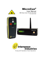
1
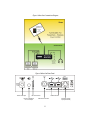
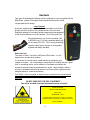
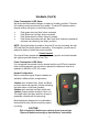
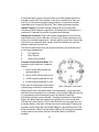
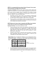
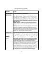
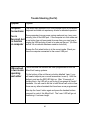
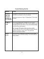
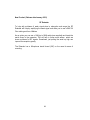
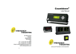
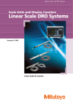
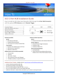
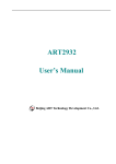
MicroCue2 User Manual With New Laser Pointer Handset Do not stare into beam Cueing and Presentation Control Specialists Contents: Introduction 3 Safety Instructions 4 Diagrams 5 Laser Handset and safe use 6 Classic Handset 7 Regulations Compliance 8 Environmental 13 Operating Instructions 13 Programming Special Cues 16 Loss of Signal 17 Trouble Shooting 18 Radio Frequency System 23 Equipment Supplied and Accessory Options 23 Technical Support Contact 2 23 Introduction MicroCue2 is the mobile professional’s 1st choice presentation cueing system. Featuring USB interfacing, MicroCue2 can connect to computers and directly control up to 2 PowerPoint presentations as in main and backup or a separate presentation for notes etc., as well as providing visual and audible cues. The system design provides for a highly portable and a quick, easy-to-set-up presentation control system. MicroCue2 is based on the Interspace Industries MasterCue series platform, retaining proven features such as the robust case design and the AV industrial grade wireless RF system. With 3 buttons the presenter can request to go backwards as well as forwards if required, or to communicate an alternative presentation function (e.g. go to black or restart). The visual and audible cues are easy to understand and designed to clearly indicate which button has been pushed and what cue action is required. MicroCue2 - For Professional Presentations on the Move! We hope MicroCue2 exceeds your expectations and welcome any feedback that you have about this or any of our products. Thank you. The Interspace Industries Team www.interspaceind.com 3 Safety Instructions All safety and operating instructions should be read before this product is operated and should be retained for further reference. Please adhere to all the warnings on this product and in these operating instructions. Please follow these instructions carefully. Power. Only use the power source indicated on the device. Devices equipped with a grounded plug should only be used with a grounded type outlet. In no way should this grounding be disconnected, modified or suppressed. Power Supply Lead. To unplug the device always pull by the plug itself, not the power supply lead. The power source outlet should always be near the MicroCue main unit and easily accessible. Ensure the power supply lead cannot be walked on or damaged by items placed on or against it. Do not use if the power supply lead is damaged. Using the device with a damaged power supply lead may expose you to electric shock or other hazards. Check the condition of the power supply lead regularly. Contact your dealer or service centre immediately for a replacement if damaged. Keep Away From Harmful Substances To prevent the risk of electric shock and fire, do not expose this device to rain, humidity or intense heat sources (such as radiators or direct sunlight). Avoid using this equipment in environments where there is excessive heat, dust, moisture, chemicals, vibration or mechanical shocks. Slots and Openings. These are designed into the device for ventilation and to avoid overheating. Always ensure these openings remain clear. Do not attempt to insert anything into these openings under any circumstances. If liquids have been spilled on, or objects have fallen into the product it must be checked by a qualified technician before reusing. Connections. All inputs and outputs (except for power input) are TBTS defined under EN60950. DO NOT OPEN SYSTEM DUE TO HIGH VOLTAGE. DO NOT IMMERSE IN WATER. Servicing. Do not attempt to service this product yourself. Should an unauthorised person attempt to either open the covers or service our products, it may invalidate your Limited Factory Warranty. In addition, opening or removing covers and screws may expose you to electric shocks or other hazards. Refer all servicing to qualified service personnel. 4 Figure 1 MicroCue Connections Diagram Figure 2 MicroCue Rear Panel 12VDC Power Input RF Level Indicator Mini Jack Headphone Cue Tone Output USB Connections BNC Aerial Connector 5 Keyboard Program Input (PS2 Socket) Handsets Two types of handsets with different button configurations can be supplied with the MicroCue2 system. The original classic handset and one with a laser incorporated into the design. Laser Handset A slimmer, slightly longer handset that sits comfortably in your hand. A finger notch on the rear of the handset anchors it to your hand. Extensive redesign of the internal antenna means we have squeezed a little bit more distance out of this handset. Over 100m open field. We use 2 batteries:- one for the transmitter, (AA or MN1500 size, 1.5V) and a separate battery just for the Laser (CR2, 3V). This is a high power/high capacity battery that is common in photographic systems and readily available. Safe Laser Use The Laser is Class 2, less than 1mW green 532nm laser. It is 10x brighter than an equivalent red laser. It is important to use the laser in a safe manner by highlighting your images on screens. It is not advisable to use a laser on a monitor that has a glass front, or something similar, as the reflection of the beam could reflect into someone's eyes and may cause discomfort or worse. Use the beam in either a circular or backwards and forwards motion to circle an outline, highlight an item being discussed or, underline something. CAUTION – Use of controls or adjustments or performance of procedures other than those specified herein may result in hazardous radiation exposure DO NOT SHINE INTO THE SKY AT AIRCRAFT — You will be arrested, fined and imprisoned in many countries! LASER RADIATION DO NOT STARE INTO BEAM 532nm ,1mW IEC/EN 60825-1:2007 Complies with 21 CFR 1040.10 & 1040.11 except for deviation Pursuant to Laser No. 50, dated June 24, 2007 FCC ID T3QI2TXL 6 Handsets (Cont’d) Power Consumption & LED Status We have made the handset intelligent in respect of its battery condition. The state of the battery can be monitored on the handset. The dual LED indicators above the push buttons will light-up in the following formats: Flash green when the ‘Next’ button is pressed Flash Red when the ‘Back’ button is pressed Flash Amber when the ‘Black’ button is pressed Flash Amber twice when both the ’Back’ and ’Next’ buttons are pressed at the same time indicating ‘low’ battery condition. NOTE - Should the battery be unable to drive the RF circuitry accurately, the dual LEDs will flash Red quickly without transmitting. If this happens, you will need to replace the battery to obtain the correct operation. Classic Handset The original Classic handset has proved to be a very popular and trusted handset with a great open field distance of over 75m. Power Consumption & LED Status If no cue signals are received from the handset and the cue LED on the handset does not illuminate when any cue button is pressed, the battery will need to be replaced. An MN1604 or PP3, 9V is used. Handset Configuration Both the Laser and original Classic handsets are available in different button configurations:3-button which includes ‘Next’, ‘Back’ and ‘Black’ as shown above and opposite. (3 button excluding the Laser button on the Laser handset); 2-button which excludes the ‘Black’ button and 1-button (Classic handset model) for ‘Next’ only. This single button has been useful for nervous or presenters unfamiliar with the technology. Both handsets are designed to be comfortable in the hand whilst being functional and they require no training. CAUTION ! Risk of explosion if batteries are replaced by an incorrect type. Dispose of batteries according to manufacturers’ instructions 7 FCC STATEMENTS Interspace Industries MicroCue2 Made In UK This device complies with Part 15 of the FCC Rules. Operation is subject to the following two conditions: (1) This device may not cause harmful interference, and (2) this device must accept any interference received, including interference that may cause undesired operation. Interspace Industries 4650 South Butterfield Drive Tucson AZ85714 United States of America Tel Office: 520 689 4237 Warning ! Any modification or changes made to this device, unless explicitly approved by Interspace Industries, will invalidate the authorisation of this device. Operation of an unauthorised device is prohibited under Section 302 of the Communications Act of 1934, as amended, and Subpart I of Part 2 of Chapter 47 of the Code of Federal Regulations. NOTE: This equipment has been tested and found to comply with the limits for a Class B digital device, pursuant to Part 15 of the FCC Rules. These limits are designed to provide reasonable protection against harmful interference in a residential installation. This equipment generates, uses and can radiate radio frequency energy and, if not installed and used in accordance with the instructions, may cause harmful interference to radio communications. However, there is no guarantee that interference will not occur in a particular installation. If this equipment does cause harmful interference to radio or television reception, which can be determined by turning the equipment off and on, the user is encouraged to try to correct the interference by one or more of the following measures: -- Reorient or relocate the receiving antenna. -- Increase the separation between the equipment and receiver. -- Connect the equipment into an outlet on a circuit different from that to which the receiver is connected. -- Consult the dealer or an experienced radio/TV technician for help. 8 FCC COMPLIANCE INFORMATION STATEMENT DECLARATION OF CONFORMITY Manufacturer: Interspace Industries Responsible Party in the USA: Interspace Industries 4650 South Butterfield Drive Tucson, AZ85714, USA Tel Office: 520 689 4237 Product: MicroCue2 Authorisation Procedure: Declaration of Conformity This device complies with Part 15 of the FCC Rules. Operation is subject to the following two conditions: (1) this device may not cause harmful interference, and (2) this device must accept any interference received, including interference that may cause undesired operation. We, Interspace Industries, have determined that the above named equipment has been shown to comply with the applicable technical standards. Furthermore, we warrant that each unit of equipment marketed is identical to the unit tested and found acceptable with the standards. The records maintained continue to reflect the equipment being produced within the variation that can be expected due to quantity production and testing on a statistical basis. David J Humphrys, Managing Director Interspace Industries Unit 1a 126 Great North Road Hatfield, Herts AL9 5JN UK November 2011 9 EC DECLARATION OF CONFORMITY TO R&TTE DIRECTIVE 1995/5/EC Manufacturer: Hive Industries Ltd - Interspace Industries Product: MicroCue2 & I2TX-1 or –2 or –3 & i2TX-2L or –3L Conformity Assessment: Annex III; Internal production control plus specific apparatus tests Reference standards used for presumption of conformity: Article 3.1a EN 60950 2006/A1: 2010 Article 3.1b EN 301 489-3 v1.4.1. : EN301 489-1 v1.8.1 Article 3.2 EN 300 220-2 V2 3.1 EN 55103-1:2009 (Emissions) / EN 55103-2:2009 (Immunity) Declaration We, Interspace Industries, declare under our sole responsibility that the essential radio test suites have been carried out and that the above product to which this declaration relates is in conformity with all the applicable essential requirements of EU Directive 1995/5/EC David J Humphrys, Managing Director Interspace Industries Unit 1a, 126 Great North Road Hatfield, Hertfordshire, AL9 5JN United Kingdom Date: November 2011 EC DECLARATION OF CONFORMITY TO R&TTE DIRECTIVE 1995/5/EC English Hereby, Interspace Industries, declares that this “MicroCue2” is in compliance with the essential requirements and other relevant provisions of Directive 1999/5/EC. Finnish Interspace Industries vakuuttaa täten että “MicroCue2” tyyppinen laite on direktiivin 1999/5/EY oleellisten vaatimusten ja sitä koskevien direktiivin muiden ehtojen mukainen. Swedish Härmed intygar Interspace Industries att denna “MicroCue2” står I överensstämmelse med de väsentliga egenskapskrav och övriga relevanta bestämmelser som framgår av direktiv 1999/5/EG. 10 Danish Undertegnede Interspace industries erklærer herved, at følgende udstyr “MicroCue2” overholder de væsentlige krav og øvrige relevante krav i direktiv 1999/5/EF Dutch Hierbij verklaart Interspace industries dat het toestel “MicroCue2” in overeenstemming is met de essentiële eisen en de andere relevante bepalingen van richtlijn 1999/5/EG Bij deze verklaart Interspace industries dat deze “MicroCue2” voldoet aan de essentiële eisen en aan de overige relevante bepalingen van Richtlijn 1999/5/EC. French Par la présente Interspace Industries déclare que l'appareil “MicroCue2” est conforme aux exigences essentielles et aux autres dispositions pertinentes de la directive 1999/5/CE Par la présente, Interspace Industries déclare que ce “MicroCue2” est conforme aux exigences essentielles et aux autres dispositions de la directive 1999/5/CE qui lui sont applicables German Hiermit erklärt Interspace Industries, dass sich dieser/diese/dieses “MicroCue2” in Übereinstimmung mit den grundlegenden Anforderungen und den anderen relevanten Vorschriften der Richtlinie 1999/5/EG befindet". (BMWi) Hiermit erklärt Interspace Industries die Übereinstimmung des Gerätes “MicroCue2” mit den grundlegenden Anforderungen und den anderen relevanten Festlegungen der Richtlinie 1999/5/EG. (Wien) Greek ΜΕ ΤΗΝ ΠΑΡΟΥΣΑ Interspace Industries ΔΗΛΩΝΕΙ ΟΤΙ “MicroCue2” ΣΥΜΜΟΡΦΩΝΕΤΑΙ ΠΡΟΣ ΤΙΣ ΟΥΣΙΩΔΕΙΣ ΑΠΑΙΤΗΣΕΙΣ ΚΑΙ ΤΙΣ ΛΟΙΠΕΣ ΣΧΕΤΙΚΕΣ ΔΙΑΤΑΞΕΙΣ ΤΗΣ ΟΔΗΓΙΑΣ 1999/5/ΕΚ Italian Con la presente Interspace Industries dichiara che questo “MicroCue2” è conforme ai requisiti essenziali ed alle altre disposizioni pertinenti stabilite dalla direttiva 1999/5/CE. Spanish Por medio de la presente Interspace Industries declara que el “MicroCue2” cumple con los requisitos esenciales y cualesquiera otras disposiciones aplicables o exigibles de la Directiva 1999/5/CE Portuguese Interspace Industries declara que este “MicroCue2” está conforme com os requisitos essenciais e outras disposições da Directiva 1999/5/CE. 11 ADDITIONAL DECLARATION OF CONFORMITY We declare under our sole responsibility that the product MicroCue2 To which this declaration relates is in conformity with the following standards or other normative documents: EN55103-1 & EN55103-2 1966 (Specific for professional Audio Visual Products). Used in environment as defined under E2 Commercial and Light industry (example Theatres) EN 60950 2006/A1: 2010 Following the provisions of the EEC Directive 89/336/EEC and 73/23/EEC Dave Humphrys Managing Director, Interspace Industries Ltd Issued: November 2011 12 Environmental WEEE and RoHS Compliance. MicroCue2 and its associated accessories have been manufactured and sold in accordance with the requirements of the EC WEEE and RoHS directives. Please return all end-of-life items to your supplier, or Interspace Industries directly, for appropriate disposal. Packaging Materials: Cardboard box: Grade 150 K/T ‘B’ (Single Walled Corrugated - Brown Kraft) Electrical CE Mark. MicroCue and its associated accessories have been designed, manufactured and certified to comply with all requirements of the European CE standard. Including EN 550103 Operating Instructions Unpacking and Connections. Unpack the main unit and place on a flat surface within easy access for the Operator (see Fig 1). Connect the aerial to the BNC connector on the rear of the main unit (see Fig 2) and position so the aerial is vertical. Power and Start up. MicroCue2 can be powered using either the USB connection to a computer or an optional 12VDC power pack (part number: PSU). After connecting either power source to the main unit the system will do a short test, during which the display on the main unit will flash green once, then red once. The presenter control selector button will remain on to show that the system is working correctly and both USB ports are enabled if computers are connected. RF Signal Strength. A Green LED RF level indicator on the rear of the main unit (see Fig 2) displays the RF signal strength of the handset when any cue button is pressed. If any of the RF level indicator LEDs remain on between cues from the handset then this is background RF signal interference which could reduce the performance of MicroCue2. Try repositioning the main unit away from electrical/ electronic equipment to reduce this as much as possible. Basic Operation. Check the system by momentarily pressing any of the handset buttons to give a cue. The display on the main unit will strobe green if the ‘Next’ (green) button is pressed and red if the ‘Back’ (red) button is pressed. Pressing the ‘Black’ button will cause the display to go fixed red to show it is in a Black, paused state. Pushing any button will cause it to come out of Black/Paused mode only. 13 If the system does not give cue signals when any of the handset buttons are pressed, check the RF level indicator on the rear of the MicroCue2 main unit (see Fig 2). If this shows a signal is being received, it confirms the handset code needs to be ‘learned’ by MicroCue2 (see ‘Learning Handsets’ section). Handset Timeout. To ensure maximum battery life and to comply with international Radio Frequency regulations, the handset will only transmit for a maximum of 5 seconds if any button is pressed and held down. Headphone Connection. Plug a set of stereo headphones into the cue tone output socket on the rear of the main unit (see Fig 2). Whilst pressing any cue button on the handset repeatedly at 1 second intervals, adjust the volume of the cue tones for a comfortable level, using a small flat screwdriver through the aperture underneath the main unit. The cue tone audio output mini jack socket connections are as follows (mono out on stereo headphones): Tip: Signal out Ring: Ground Sleeve: No connection Presenter Control Selector Mode. The presenter control button has 4 states as follows: 1. Both A and B USB channels are selected (default) 2. Both A and B USB channels are off 3. A USB channel is selected, B is off 4. B USB channel is selected, A is off Each press of the presenter control button cycles through to the next of these states. Figure 3 Presenter Control States MicroCue2 will start in the default state (A and B selected). In this mode and with MicroCue2 connected to two computers via the A and B USB ports (see Fig 2), the presenter can simultaneously control two different PowerPoint presentations directly from the handset. Pressing the presenter control button while in the default state will change to full operator-only control mode (both USB ports off; state option 2 in Fig 3). MicroCue2 will now only signal cues via the visual display on the main unit and the cue tone audio output. Pressing the presenter control button again will enable USB port A and another press of the button will deselect USB port A and enable USB port B. Pressing the presenter control button once more will restore to the default state (A and B both enabled). 14 NOTE: It is recommended that you always fully test Presenter Control mode with the computer thoroughly during rehearsals! ‘Learning’ the Handset. MicroCue2 uses coded transmission data to identify each handset. This ensures that only those handsets programmed to each MicroCue 2 will be able to send cue signals; making it impossible for the system to receive false cue commands. Up to 16 handsets can be programmed to each MicroCue 2 main unit if required. To learn the handset coding: 1. Momentarily press the ‘Learn’ button on the underside of the MicroCue 2 main unit using a suitable tool (e.g. a ballpoint pen or similar). The red LED will illuminate to confirm the system is ready to learn a new handset. 2. Press any button on the handset to send a cue signal to MicroCue2. The visual display on the front panel will confirm the cue has been received and that the system has learned the new handset. NOTE: Whenever the ‘Learn’ button is pressed, both USB ports are disabled and no cues can be sent to any computers that may be connected Handset Code Erase. To erase all handset learn codes: 1. Press and hold the ‘Learn’ button on the underside of the MicroCue2 main unit using a suitable tool (e.g. a ballpoint pen or similar). The front panel display will cycle through illuminating the two outer LEDS, then the two centre LEDS, then leave the two outer LEDS illuminated to confirm MicroCue2 is in erase mode. 2. Release the Learn button and MicroCue2 will re-start without any handsets being programmed. MicroCue2 will now be unable to receive any cue commands until a new handset has been learned. System Reset. Each of the MicroCue2 USB ports can be independently reset to factory default settings - including any handset special cue commands. To reset each A and B USB port, the Presenter Control button must be in the following states: Start with: To reset USB port: A B Figure 4 Presenter Control States A and B 1. With the Presenter Control button on the front panel in the required starting state (see Fig 4 above), press and hold the presenter control button and also momentarily press the ‘Learn’ button on the underside of the main unit 15 using a suitable tool (e.g. a ballpoint pen or similar). The visual display on the front panel will turn green to confirm the reset. 1. Release the Presenter Control button and the system will go though the normal start up routine. 2. Repeat for each channel that is required to be erased. NOTE: System reset does NOT erase the handset ‘learn’ coding. Programming Special Cues The handset buttons are default programmed to simulate keyboard commands that can be used to control PowerPoint when in slideshow mode; i.e. for NEXT, for BACK and the letter ‘B’ for Black (which makes the screen go to black). These buttons can also be reprogrammed to send different keyboard commands to the computer running PowerPoint presentations if required. Some common alternative keyboard commands include: Keying the letter ‘W’ takes the screen to white Keying any number then skips to that number slide in the presentation Keying ‘1’ then resets the presentation to the 1st slide Keying the letters ‘z’, ‘x’, ‘c’ or ‘v’ have no effect during a PowerPoint presentation so programming any of these to a handset button will disable that button. MicroCue2, can also be programmed so that channels A and B can respond differently using the same handset. For example, it is possible to program channel A to go to ‘black’ and channel B to go to ‘white’ when the round black button is pressed on the handset. To reprogram MicroCue2: 1. Ensure that the Channel A USB port is plugged into a computer using the USB cable supplied (see Fig 2). Channel A is the primary power input required for programming MicroCue2. 2. Next, plug a computer keyboard with a PS2 connection into the Keyboard Program Input (PS2 socket) on the rear panel of MicroCue2 (see Fig 2) and check the keyboard can control the computer by using keys as normal. It can be helpful to have PowerPoint running on the computer during programming although this is not essential. Note: The CTRL and FN keys will not operate whilst connected to MicroCue2 in this way; only the standard alpha-numeric keys will operate. Note also that when connected, the keyboard will control both the A and B USB ports in exactly the same way i.e. pressing ‘B’ on the keyboard will send the ‘Black’ command to both USB ports and the screens of any computers that are connected and in PowerPoint slideshow mode, will go to black. 16 3. With the Presenter Control button on the front panel in the required starting state (see Fig 4), press and hold the presenter control button. After about 6 seconds the visual display will cycle through the three handset button programming points: Green only on the right of the display (NEXT button command point) Red only on the left of the display (BACK button command point) Amber (BLACK button command point) 4. Releasing the Presenter Control button at any of these points will leave the system ready to receive a new command for that particular button on the handset. 5. Once the system is ready to receive a new command for the button you wish to re-program, press the key/s on the keyboard to simulate the command you require (e.g. press the letter ‘w’ to make the screen go to white) 6. Press the Presenter Control button once more momentarily to store the new command. 7. Repeat this procedure to program each of the three handset buttons as required. 8. To program a different USB channel, start with the presenter control button in the required alternative state (see Fig 4), then repeat the entire procedure from 1 above. 17 Trouble Shooting Symptom Try this General RF There are many factors that can affect loss of RF signal; someproblems: times a small room can be more of a problem than a big room due to reflections and absorption. Ensure that you have at least 3 of the 4 LEDs lit on the RF level Intermittent Indicator, (rear of the unit) when you push the remote control. For continued results, ensure there are 2 LEDs difference to any loss of “background” noise. Make sure there is a good line of sight becontrol tween the transmitter and the receiver. People between the transmitter and the receiver will act like sponges to the signal and can absorb the signal. This can be seen when the equipment appears to work at rehearsal and the room is empty, but problems can occur when the room is full. As we do not operate on or near 2.4 GHz—Bluetooth & WIFI, we are not usually interfered with by these frequencies. General RF Ensure the MicroCue2 aerial is vertically orientated. problems: Positioning Position the MicroCue2 aerial within line-of-sight of the handsets, without large metallic objects in between as much as possible. The aerial can also be placed remote from the main unit using a 50 ohm BNC-BNC coaxial extension cable if required (max cable length: 4m). Lift the unit up to get some height. Avoid electrical/electronic interference by positioning the MicroCue2 main unit away from equipment as much as possible. If this is consistent in the same room, we would recommend looking at the MasterCue V6 system which has other features including a remote RF receiver and back-up wired buttons 18 Trouble Shooting (Cont’d) Symptom Try this Handset does This can be because of 3 main reasons:not function First : Check the battery. Does the amber LED (on the Classic) handset light up? If not change the 9V battery. On the Laser handset do the Indicator LEDs light up to show anything? If there is only red flashing – change the battery. If the correct colour (when pressed) is shown followed by an amber light—change the battery as it is low. Second: ‘Learning’. Does the RF level on the rear of the MicroCue2 show that a signal is made? If so then ‘learn’ the handset to the unit. Third: Have tried to ‘learn’ and nothing happens? Then possibly the memory of handsets has exceeded 16 handsets and is full. Press and hold the ‘learn’ button until the LED goes out (to erase all handsets), then re-learn the new handset once again. If this does not work - there may be a technical problem. Battery life:Classic: Laser: The Classic and Laser handsets will stop transmitting if the battery is at a low state as it could cause incorrect transmission (which is prohibited). There is an automatic inbuilt electronic cut-off to avoid this. The Classic will not show any LEDs on the transmitter if the battery is dead – check by replacing the battery (PP3). Laser handset: the indicator LEDs on the handset have 2 states for battery indication. After a button has been pressed the LEDs will show green, red or amber to correspond with the button pressed, if the battery is low but working and, after 2 seconds after these indications, the LEDs will flash amber twice. The battery should (depending on use) last more than a day in this state. Change the AA battery at your earliest convenience. If the LEDs only flash RED, whatever button has been pushed, then the battery is nearly dead and needs replacing immediately. Of course a fully flat battery will do nothing and will also need changing! 19 Trouble Shooting (Cont’d) Symptom Try this Computer The MicroCue2 appears to the USB computer input as a standard Connections: keyboard and does not require any drivers for standard operation. Cue is Received, but no function on computer Some computers have a power saving mode and can (very occasionally) turn off the USB port. If the computer is in this mode and a cue button has not been made for some time, you may have to unplug the USB and plug it back in to wake up the port. (On MasterCue V6 an indicator has been made to show this). Ensure the Port select button is in the correct mode. Check you have the computer connected to the correct USB port. 2 MicroCue2 in two rooms operating each other This is because the handset has been programmed to both the MicroCue2 cueing systems. On the bottom of the unit there is a button labelled ‘Learn’ ( you will need a ballpoint pen or small screwdriver to use it). Hold the button in and see the RED LED light up. After 10 seconds of holding this in, the LED will go out to say it has erased all ‘taught’ handsets. You will need to do this to both MicroCue2 units in case there are any others handsets that have been cross-programmed. Now tap the ‘Learn’ button again and press the handset buttons you want to control this MicroCue2. The ‘Learn’ LED will go out confirming it has been taught. 20 Trouble Shooting (Cont’d) Symptom Try this Received cues, but incorrect function on the computer It is possible to have a MicroCue2 that has been re-programmed with different commands to control the computer. PC Mac or Linux PC Computer USB Interface. Suitable only for PC systems running a WINDOWS XP, Vista or Win 7 or later operating system. To ensure optimum performance, we can only recommend using the USB A-B type cable supplied. Follow the instructions on Page 15 ‘System Reset’. This is easily corrected. Mac Computer USB Interface. When connecting to a Mac computer USB input, when the Mac keyboard assistant requests keyboard confirmation, simply ‘cancel’ this request and MicroCue2 will operate normally. Further issues Should you find an unexpected occurrence or problem, please contact us so we can advise accordingly. Our contact details are shown overleaf. 21 New Product. (Release date January 2012) RF Extender To help with problems of weak signals due to absorption and range the RF Extender will help by amplifying the weak signal and allow you to use a BNC 50 Ohm cable great than 4 Metres. As an option you can use a 10M (up to 50M) cable (user supplied) and locate the aerial closer to the presenter. This will help in those rooms where which are known problems for RF signals. Sometimes, just putting the aerial up high can improve the reception greatly. The Extender has a Microphone stand thread (3/8”) on the case for ease of mounting. 22 Radio Frequency System MicroCue2 uses a proven RF system for all wireless applications. Operating frequency: 434.075MHz (UK, Europe & USA) Transmission method: FM (Pure FSK) Maximum transmit power: 10mW (EU) 11mV/m @3m (USA) This frequency is open and licence exempt for UK, Europe and USA. Other countries should consult their respective authorities. The system used is a coded transmission where the receivers are programmed to the transmitters which each have individual and unique codes. Nominal range of the transmitters is typically 75M in an enclosed venue. Equipment Supplied 1 x MicroCue2 main unit 1 x BNC adjustable angle aerial 1 x 3-button handset 2 x USB A-B cable Optional Accessories 12V DC Power Supply 1, 2, or 3-button classic handset Dual or triple-button laser handset RF extender (battery powered) Technical Support or Sales Enquiries Interspace Industries Head Office: +44 (0) 870 770 8088 Emergency Technical Support Hot Line: +44 (0) 7976 385 046 Website: www.interspaceind.com 23 Unit 1a 126 Great North Road Hatfield, Hertfordshire AL9 5JN United Kingdom Tel: +44 (0) 870 770 8088 Fax: +44 (0) 870 770 8089 Email: [email protected] www.interspaceind.com 24