1
Pressure transmitter
SITRANS P, DS III Series with PROFIBUS PA
Operating Instructions· 09/2012
SITRANS
Answers for industry.
Introduction
1
Safety information
2
Description
3
Installing / mounting
4
Connecting up
5
Operation
6
Operator control functions via
PROFIBUS
7
Functional safety
8
Configuration/project
engineering
9
SITRANS
Pressure transmitter
SITRANS P, Series DS III with
PROFIBUS PA
Operating Instructions
7MF4.34
09/2012
A5E00053276-06
Commissioning
10
Repair and maintenance
11
Interrupts, error and system
alarms
12
Technical data
13
Dimension drawings
14
Spare parts / accessories
15
Appendix
A
List of abbreviations/
acronyms
B
Legal information
Warning notice system
This manual contains notices you have to observe in order to ensure your personal safety, as well as to prevent
damage to property. The notices referring to your personal safety are highlighted in the manual by a safety alert
symbol, notices referring only to property damage have no safety alert symbol. These notices shown below are
graded according to the degree of danger.
DANGER
indicates that death or severe personal injury will result if proper precautions are not taken.
WARNING
indicates that death or severe personal injury may result if proper precautions are not taken.
CAUTION
indicates that minor personal injury can result if proper precautions are not taken.
NOTICE
indicates that property damage can result if proper precautions are not taken.
If more than one degree of danger is present, the warning notice representing the highest degree of danger will be
used. A notice warning of injury to persons with a safety alert symbol may also include a warning relating to property
damage.
Qualified Personnel
The product/system described in this documentation may be operated only by personnel qualified for the specific
task in accordance with the relevant documentation, in particular its warning notices and safety instructions. Qualified
personnel are those who, based on their training and experience, are capable of identifying risks and avoiding
potential hazards when working with these products/systems.
Proper use of Siemens products
Note the following:
WARNING
Siemens products may only be used for the applications described in the catalog and in the relevant technical
documentation. If products and components from other manufacturers are used, these must be recommended or
approved by Siemens. Proper transport, storage, installation, assembly, commissioning, operation and
maintenance are required to ensure that the products operate safely and without any problems. The permissible
ambient conditions must be complied with. The information in the relevant documentation must be observed.
Trademarks
All names identified by ® are registered trademarks of Siemens AG. The remaining trademarks in this publication
may be trademarks whose use by third parties for their own purposes could violate the rights of the owner.
Disclaimer of Liability
We have reviewed the contents of this publication to ensure consistency with the hardware and software described.
Since variance cannot be precluded entirely, we cannot guarantee full consistency. However, the information in
this publication is reviewed regularly and any necessary corrections are included in subsequent editions.
Siemens AG
Industry Sector
Postfach 48 48
90026 NÜRNBERG
GERMANY
Order number: A5E00053276
Ⓟ 10/2012 Technical data subject to change
Copyright © Siemens AG 2012.
All rights reserved
Table of contents
1
2
3
Introduction...................................................................................................................................................9
1.1
Purpose of this documentation......................................................................................................9
1.2
Product information.......................................................................................................................9
1.3
History...........................................................................................................................................9
1.4
Scope of the instructions.............................................................................................................10
1.5
Checking the consignment..........................................................................................................10
1.6
Transportation and storage.........................................................................................................10
1.7
Notes on warranty.......................................................................................................................11
Safety information.......................................................................................................................................13
2.1
2.1.1
2.1.2
Precondition for use.....................................................................................................................13
Laws and directives.....................................................................................................................13
Conformity with European directives...........................................................................................13
2.2
Improper device modifications.....................................................................................................14
2.3
Requirements for special applications.........................................................................................14
2.4
Use in hazardous areas...............................................................................................................15
Description..................................................................................................................................................17
3.1
System configuration...................................................................................................................17
3.2
Application...................................................................................................................................18
3.3
Structure......................................................................................................................................20
3.4
Structure of the label and approval plate.....................................................................................21
3.5
Measuring point label layout........................................................................................................22
3.6
3.6.1
3.6.2
3.6.3
3.6.3.1
3.6.3.2
3.6.3.3
3.6.3.4
3.6.3.5
3.6.3.6
3.6.3.7
Principle of operation...................................................................................................................22
Overview of mode of operation....................................................................................................22
Operation of the electronics.........................................................................................................23
Principle of operation of the measuring cell.................................................................................24
Measuring cell for gauge pressure..............................................................................................25
Measuring cell for differential pressure and flow rate..................................................................25
Measuring cell for level................................................................................................................26
Measuring cell for absolute pressure from the differential pressure series.................................27
Measuring cell for absolute pressure from the gauge pressure series........................................28
Measuring cell for gauge pressure, front-flush membrane..........................................................28
Measuring cell for absolute pressure, front-flush membrane......................................................29
3.7
Remote seal................................................................................................................................30
3.8
SIMATIC PDM.............................................................................................................................30
3.9
PROFIBUS..................................................................................................................................31
SITRANS P, Series DS III with PROFIBUS PA
Operating Instructions, 09/2012, A5E00053276-06
3
Table of contents
3.9.1
3.9.2
3.9.3
4
5
6
4
Transmission technology.............................................................................................................31
Bus topology................................................................................................................................31
Properties....................................................................................................................................32
Installing / mounting....................................................................................................................................33
4.1
4.1.1
4.1.2
4.1.2.1
Basic safety instructions..............................................................................................................33
Installation location requirements................................................................................................37
Proper mounting..........................................................................................................................38
Incorrect mounting.......................................................................................................................38
4.2
Disassembly................................................................................................................................39
4.3
4.3.1
4.3.2
4.3.3
Installation (except level).............................................................................................................39
Installation mounting (except for level)........................................................................................39
Installation (except level).............................................................................................................40
Fastening.....................................................................................................................................41
4.4
4.4.1
4.4.2
4.4.3
"Level" installation.......................................................................................................................43
Instructions for level installation...................................................................................................43
Installation for level......................................................................................................................44
Connection of the negative pressure line....................................................................................45
4.5
4.5.1
4.5.2
"Remote seal" installation............................................................................................................47
Remote seal installation..............................................................................................................47
Installation of the remote seal with the capillary line...................................................................49
4.6
Turing the measuring cell against housing..................................................................................54
4.7
Rotating the display.....................................................................................................................55
Connecting up.............................................................................................................................................57
5.1
5.1.1
Basic safety instructions..............................................................................................................57
Unsuitable cables and/or cable glands........................................................................................57
5.2
5.2.1
Connecting the device.................................................................................................................60
PROFIBUS assembly guidelines.................................................................................................60
5.3
Connecting the M12 connector....................................................................................................62
Operation....................................................................................................................................................65
6.1
Overview of operation..................................................................................................................65
6.2
Basic safety instructions..............................................................................................................66
6.3
Information on operation..............................................................................................................66
6.4
6.4.1
6.4.2
6.4.3
6.4.4
6.4.5
Display.........................................................................................................................................67
Display elements.........................................................................................................................67
Units display................................................................................................................................68
Error display................................................................................................................................68
Mode display...............................................................................................................................69
Status display..............................................................................................................................69
6.5
6.5.1
6.5.2
6.5.3
6.5.4
Local operation............................................................................................................................70
Control elements for local operation............................................................................................70
Operation using buttons..............................................................................................................73
Setting/adjusting electrical damping............................................................................................73
Calibrate zero point.....................................................................................................................74
SITRANS P, Series DS III with PROFIBUS PA
Operating Instructions, 09/2012, A5E00053276-06
Table of contents
6.5.5
6.5.6
6.5.7
6.5.8
6.5.9
6.5.10
6.5.11
6.5.12
6.5.13
7
Locking of buttons and functions.................................................................................................75
Measured value display...............................................................................................................76
Unit..............................................................................................................................................78
Bus address.................................................................................................................................81
Device operation type..................................................................................................................82
Position of the decimal point........................................................................................................83
Display of the zero-point adjustment...........................................................................................84
LO calibration..............................................................................................................................85
HI calibration................................................................................................................................86
Operator control functions via PROFIBUS.................................................................................................89
7.1
7.1.1
7.1.2
7.1.3
7.1.3.1
7.1.3.2
7.1.3.3
7.1.4
7.1.5
7.1.6
Communications structure for PROFIBUS PA............................................................................89
Overview......................................................................................................................................89
Block model for collection and processing of measured values..................................................89
Pressure transducer block...........................................................................................................92
Pressure transducer block (transducer block 1)..........................................................................92
Linearization type function group.................................................................................................94
Units of the pressure transducer block........................................................................................96
Electronics temperature transducer block...................................................................................97
Analog input function block..........................................................................................................98
Totalizer function block................................................................................................................99
7.2
Overview of operating functions................................................................................................100
7.3
Measurement.............................................................................................................................100
7.4
7.4.1
7.4.2
7.4.3
7.4.4
7.4.5
7.4.6
Settings......................................................................................................................................101
Overview of settings..................................................................................................................101
Settings......................................................................................................................................101
Pressure measurement.............................................................................................................101
Level measurement...................................................................................................................102
Flow measurement....................................................................................................................105
Adjusting to a desired process value.........................................................................................108
7.5
Electrical damping.....................................................................................................................110
7.6
Key lock and write protection.....................................................................................................110
7.7
Warning and alarm limits...........................................................................................................111
7.8
7.8.1
7.8.2
7.8.3
Failure behavior.........................................................................................................................112
Overview of failure behavior......................................................................................................112
Output........................................................................................................................................113
Totalizer output..........................................................................................................................113
7.9
7.9.1
7.9.2
7.9.3
7.9.4
7.9.5
Diagnostics functions.................................................................................................................113
Operating hours counter............................................................................................................113
Calibration interval and service interval.....................................................................................114
Clearing warning........................................................................................................................114
Clearing the alarm.....................................................................................................................115
Min/max indicator......................................................................................................................115
7.10
7.10.1
7.10.2
7.10.3
7.10.4
Simulation..................................................................................................................................116
Overview of simulation..............................................................................................................116
Simulating output.......................................................................................................................117
Simulating input.........................................................................................................................117
Simulating the pressure sensor.................................................................................................118
SITRANS P, Series DS III with PROFIBUS PA
Operating Instructions, 09/2012, A5E00053276-06
5
Table of contents
8
9
7.10.5
Simulating sensor and electronics temperature........................................................................119
7.11
Calibrating the sensor................................................................................................................119
7.12
Correcting for positional error....................................................................................................120
7.13
7.13.1
7.13.2
7.13.3
Reset.........................................................................................................................................121
Resetting to delivery state.........................................................................................................121
Warm start/restart......................................................................................................................121
Resetting the PROFIBUS address............................................................................................122
Functional safety.......................................................................................................................................123
8.1
Safety-instrumented system......................................................................................................123
8.2
Safety Integrity Level (SIL)........................................................................................................123
8.3
8.3.1
8.3.2
8.3.3
Device-specific..........................................................................................................................125
Safety function...........................................................................................................................125
Settings......................................................................................................................................126
Safety-related characteristics....................................................................................................127
8.4
Maintenance/Checking..............................................................................................................128
8.5
8.5.1
8.5.2
Add-on parts..............................................................................................................................128
Checking a device with add-on pneumatic block.......................................................................129
Checking a device with add-on remote seal..............................................................................129
8.6
8.6.1
8.6.2
8.6.3
8.6.4
8.6.5
8.6.5.1
8.6.5.2
8.6.5.3
8.6.5.4
8.6.6
8.6.6.1
8.6.6.2
8.6.7
8.6.7.1
8.6.7.2
8.6.7.3
8.6.7.4
8.6.7.5
8.6.8
8.6.8.1
8.6.8.2
8.6.8.3
8.6.9
8.6.9.1
8.6.9.2
PROFIsafe.................................................................................................................................129
Introduction................................................................................................................................129
Technical advantages of PROFIsafe.........................................................................................129
Further information....................................................................................................................131
Preconditions.............................................................................................................................132
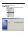
PROFIsafe Configuration..........................................................................................................132
Import EDD with SIMATIC PDM................................................................................................133
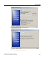
Configure CPU with HW Config.................................................................................................133
Configure device with HW Config..............................................................................................134
Configure CFC...........................................................................................................................137
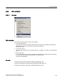
Write protection.........................................................................................................................139
Overview....................................................................................................................................139
Activate write protection using PIN in SIMATIC PDM...............................................................140
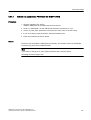
PROFIsafe Commissioning.......................................................................................................140
Activate and parameterize PROFIsafe with SIMATIC PDM......................................................141
Commission PROFIsafe with SIMATIC PDM............................................................................142
Check write protection with SIMATIC PDM...............................................................................147
Speeding up the commissioning process..................................................................................148
Resetting the device..................................................................................................................148
Quit PROFIsafe commissioning................................................................................................149
Preparations for maintenance and service................................................................................149
Deactivate PROFIsafe commissioning in SIMATIC PDM..........................................................149
Disable write protection using PIN in SIMATIC PDM................................................................149
Replacing a device....................................................................................................................150
Making settings locally...............................................................................................................150
Configuration with host system..................................................................................................151
Configuration/project engineering.............................................................................................................153
9.1
6
Cyclical data transfer.................................................................................................................153
SITRANS P, Series DS III with PROFIBUS PA
Operating Instructions, 09/2012, A5E00053276-06
Table of contents
10
11
12
13
9.2
9.2.1
9.2.2
9.2.3
9.2.4
9.2.5
Configuring................................................................................................................................153
Overview of configuration..........................................................................................................153
Configuration of user data.........................................................................................................153
Transmission of user data over PROFIBUS..............................................................................155
Status........................................................................................................................................155
Diagnosis...................................................................................................................................156
9.3
Acyclic data transfer..................................................................................................................158
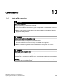
Commissioning.........................................................................................................................................161
10.1
Basic safety instructions............................................................................................................161
10.2
Introduction to commissioning...................................................................................................162
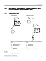
10.3
10.3.1
10.3.2
Gauge pressure, absolute pressure from differential pressure series, and absolute pressure from
gauge pressure series...............................................................................................................163
Commissioning for gases..........................................................................................................163
Commissioning with steam or liquid..........................................................................................164
10.4
10.4.1
10.4.2
10.4.3
10.4.4
Differential pressure and flow rate.............................................................................................165
Safety notes for commissioning with differential pressure and flow rate...................................165
Commissioning in gaseous environments.................................................................................166
Commissioning for liquids..........................................................................................................167
Commissioning with vapor.........................................................................................................169
Repair and maintenance...........................................................................................................................171
11.1
Basic safety instructions............................................................................................................171
11.2
11.2.1
11.2.2
11.2.3
11.2.4
Maintenance and repair work....................................................................................................174
Defining the maintenance interval.............................................................................................174
Checking the gaskets................................................................................................................175
Display in case of a fault............................................................................................................175
Changing the measuring cell and application electronics.........................................................176
11.3
11.3.1
Cleaning....................................................................................................................................176
Servicing the remote seal measuring system............................................................................177
11.4
Return procedure.......................................................................................................................178
11.5
Disposal.....................................................................................................................................178
Interrupts, error and system alarms..........................................................................................................181
12.1
Overview of status codes..........................................................................................................181
12.2
Errors.........................................................................................................................................184
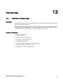
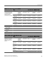
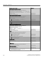
Technical data..........................................................................................................................................187
13.1
Overview of technical data........................................................................................................187
13.2
Input point..................................................................................................................................188
13.3
Output........................................................................................................................................195
13.4
Measuring accuracy..................................................................................................................195
13.5
Operating conditions..................................................................................................................201
13.6
Construction..............................................................................................................................205
SITRANS P, Series DS III with PROFIBUS PA
Operating Instructions, 09/2012, A5E00053276-06
7
Table of contents
14
15
A
B
13.7
Display, keyboard and auxiliary power......................................................................................209
13.8
Certificates and approvals.........................................................................................................210
13.9
PROFIBUS communication.......................................................................................................212
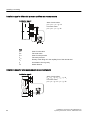
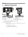
Dimension drawings.................................................................................................................................215
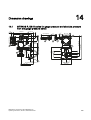
14.1
SITRANS P, DS III series for gauge pressure and absolute pressure from the gauge pressure
series.........................................................................................................................................215
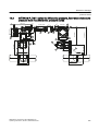
14.2
SITRANS P, DS III series for differential pressure, flow rate and absolute pressure from the
differential pressure series........................................................................................................217
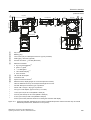
14.3
SITRANS P, DS III series for level............................................................................................220
14.4
14.4.1
14.4.2
14.4.3
14.4.4
14.4.5
SITRANS P, DS III series (flush mounted)................................................................................222
Note 3A and EHDG...................................................................................................................223
Connections as per EN and ASME...........................................................................................223
F&B and pharma flange.............................................................................................................224
PMC Style..................................................................................................................................228
Special connections...................................................................................................................229
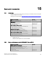
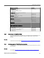
Spare parts / accessories.........................................................................................................................231
15.1
Order data.................................................................................................................................231
15.2
Spare parts/accessories for SITRANS P, Series DS III.............................................................231
15.3
Order data for SIMATIC PDM....................................................................................................233
15.4
Ordering data for PROFIBUS accessories................................................................................233
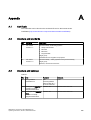
Appendix...................................................................................................................................................235
A.1
Certificate..................................................................................................................................235
A.2
Literature and standards............................................................................................................235
A.3
Literature and catalogs..............................................................................................................235
A.4
Technical support......................................................................................................................236
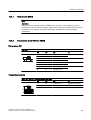
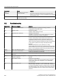
List of abbreviations/acronyms.................................................................................................................239
B.1
Pressure transmitter..................................................................................................................239
B.2
Functional safety.......................................................................................................................240
Glossary....................................................................................................................................................243
Index.........................................................................................................................................................247
8
SITRANS P, Series DS III with PROFIBUS PA
Operating Instructions, 09/2012, A5E00053276-06
1
Introduction
1.1
Purpose of this documentation
These instructions contain all information required to commission and use the device. It is your
responsibility to read the instructions carefully prior to installation and commissioning. In order
to use the device correctly, first review its principle of operation.
The instructions are aimed at persons mechanically installing the device, connecting it
electronically, configuring the parameters and commissioning it, as well as service and
maintenance engineers.
1.2
Product information
The programming manual is an integral part of the CD, which is either supplied or can be
ordered. The programming manual is also available on the Siemens homepage.
On the CD, you will also find the catalog extract with the ordering data, the Software Device
Install for SIMATIC PDM for additional installation, and the required software.
See also
Product information on SITRANS P in the Internet (http://www.siemens.com/sitransp)
Catalog process instrumentation (http://www.siemens.com/processinstrumentation/catalogs)
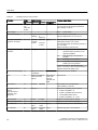
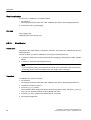
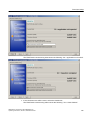
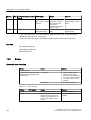
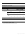
1.3
History
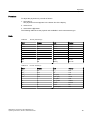
This history establishes the correlation between the current documentation and the valid
firmware of the device.
The documentation of this edition applies to the following firmware:
Edition
Firmware identifier
nameplate
System integration
Installation path for PDM
09/2012
FW:300.01.08
FW:301.01.10
PDM V6.01) + SP1
SITRANS P DSIII
PROFIsafe
FW:301.02.03
FW:301.02.04
1)
up to SP05 Hotfix 6
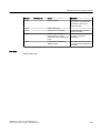
The most important changes in the documentation when compared with the respective
previous edition are given in the following table.
SITRANS P, Series DS III with PROFIBUS PA
Operating Instructions, 09/2012, A5E00053276-06
9
Introduction
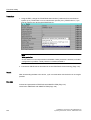
1.6 Transportation and storage
Edition
Remark
09/2012
All safety information has been revised.
The following chapters have also been changed:
● Chapter "Description > Principle of operation > Principle of operation of the measuring
cell"
● "Connecting" chapter
● "Functional safety" chapter
● "Technical data" chapter
● "Dimension drawing" chapter
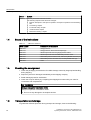
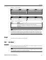
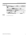
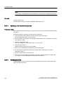
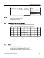
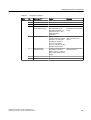
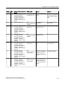
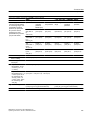
1.4
Scope of the instructions
Table 1-1
1.5
"7MF4.34" stands for:
Order number
SITRANS P, DS III series for
7MF4034
Gauge pressure
7MF4134
Gauge pressure, flush mounted diaphragm
7MF4234
Absolute pressure from the gauge pressure series
7MF4334
Absolute pressure from the differential pressure series
7MF4434
Differential pressure and flow rate, PN 32/160 (MAWP 464/2320 psi)
7MF4534
Differential pressure and flow rate, PN 420 (MAWP 6092 psi)
7MF4634
Level
Checking the consignment
1. Check the packaging and the device for visible damage caused by inappropriate handling
during shipping.
2. Report any claims for damages immediately to the shipping company.
3. Retain damaged parts for clarification.
4. Check the scope of delivery by comparing the shipping documents with your order for
correctness and completeness.
WARNING
Using a damaged or incomplete device
Danger of explosion in hazardous areas.
● Do not use any damaged or incomplete devices.
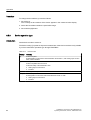
1.6
Transportation and storage
To guarantee sufficient protection during transport and storage, observe the following:
10
SITRANS P, Series DS III with PROFIBUS PA
Operating Instructions, 09/2012, A5E00053276-06
Introduction
1.7 Notes on warranty
● Keep the original packaging for subsequent transportation.
● Devices/replacement parts should be returned in their original packaging.
● If the original packaging is no longer available, ensure that all shipments are properly
packaged to provide sufficient protection during transport. Siemens cannot assume liability
for any costs associated with transportation damages.
CAUTION
Insufficient protection during storage
The packaging only provides limited protection against moisture and infiltration.
● Provide additional packaging as necessary.
Special conditions for storage and transportation of the device are listed in "Technical data"
(Page 187).
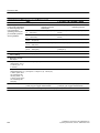
1.7
Notes on warranty
The contents of this manual shall not become part of or modify any prior or existing agreement,
commitment or legal relationship. The sales contract contains all obligations on the part of
Siemens as well as the complete and solely applicable warranty conditions. Any statements
regarding device versions described in the manual do not create new warranties or modify the
existing warranty.
The content reflects the technical status at the time of publishing. Siemens reserves the right
to make technical changes in the course of further development.
SITRANS P, Series DS III with PROFIBUS PA
Operating Instructions, 09/2012, A5E00053276-06
11
Safety information
2.1
2
Precondition for use
This device left the factory in good working condition. In order to maintain this status and to
ensure safe operation of the device, observe these instructions and all the specifications
relevant to safety.
Observe the information and symbols on the device. Do not remove any information or symbols
from the device. Always keep the information and symbols in a completely legible state.
Symbol
Explanation
Consult operating instructions
2.1.1
Laws and directives
Observe the test certification, provisions and laws applicable in your country during connection,
assembly and operation. These include, for example:
● National Electrical Code (NEC - NFPA 70) (USA)
● Canadian Electrical Code (CEC) (Canada)
Further provisions for hazardous area applications are for example:
● IEC 60079-14 (international)
● EN 60079-14 (EC)
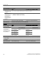
2.1.2
Conformity with European directives
The CE mark on the device is a sign of conformity with the following European directives:
SITRANS P, Series DS III with PROFIBUS PA
Operating Instructions, 09/2012, A5E00053276-06
13
Safety information
2.3 Requirements for special applications
Electromagnetic
Compatibility EMC
2004/108/EC
Atmosphère explosible
ATEX
94/9/EC
Pressure Equipment
Directive PED
97/23/EC
Directive of the European Parliament and of the Council on the
approximation of the laws of the Member States relating to
electromagnetic compatibility and repealing Directive 89/336/
EEC.
Directive of the European Parliament and the Council on the
approximation of the laws of the Member States concerning
equipment and protective systems intended for use in potentially
explosive atmospheres.
Directive of the European Parliament and of the Council on the
approximation of the laws of the Member States concerning
pressure equipment.
The standards applied can be found in the EC declaration of conformity for the device.
2.2
Improper device modifications
WARNING
Improper device modifications
Danger to personnel, system and environment can result from modifications to the device,
particularly in hazardous areas.
● Only carry out modifications that are described in the instructions for the device. Failure
to observe this requirement cancels the manufacturer's warranty and the product
approvals.
2.3
Requirements for special applications
Due to the large number of possible applications, each detail of the described device versions
for each possible scenario during commissioning, operation, maintenance or operation in
systems cannot be considered in the instructions. If you need additional information not
covered by these instructions, contact your local Siemens office or company representative.
Note
Operation under special ambient conditions
We highly recommend that you contact your Siemens representative or our application
department before you operate the device under special ambient conditions as can be
encountered in nuclear power plants or when the device is used for research and
development purposes.
14
SITRANS P, Series DS III with PROFIBUS PA
Operating Instructions, 09/2012, A5E00053276-06
Safety information
2.4 Use in hazardous areas
2.4
Use in hazardous areas
Qualified personnel for hazardous area applications
Persons who install, assemble, commission, operate and service the device in a hazardous
area must have the following specific qualifications:
● They are authorized, trained or instructed in operating and maintaining devices and systems
according to the safety regulations for electrical circuits, high pressures, aggressive and
hazardous media.
● They are authorized, trained, or instructed in carrying out work on electrical circuits for
hazardous systems.
● They are trained or instructed in maintenance and use of appropriate safety equipment
according to the pertinent safety regulations.
WARNING
Unsuitable device for the hazardous area
Danger of explosion.
● Only use equipment that is approved for use in the intended hazardous area and labelled
accordingly.
See also
Technical data (Page 187)
WARNING
Loss of safety of device with type of protection "Intrinsic safety Ex i"
If the device has already been operated in non-intrinsically safe circuits or the electrical
specifications have not been observed, the safety of the device is no longer ensured for use
in hazardous areas. There is a danger of explosion.
● Connect the device with type of protection "Intrinsic safety" solely to an intrinsically safe
circuit.
● Observe the specifications for the electrical data on the certificate and in Chapter
"Technical data (Page 187)".
SITRANS P, Series DS III with PROFIBUS PA
Operating Instructions, 09/2012, A5E00053276-06
15
Safety information
2.4 Use in hazardous areas
WARNING
Use of incorrect device parts in potentially explosive environments
Devices and their associated device parts are either approved for different types of protection
or they do not have explosion protection. There is a danger of explosion if device parts (such
as covers) are used for devices with explosion protection that are not expressly suited for
this type of protection. If you do not adhere to these guidelines, the test certificates and the
manufacturer warranty will become null and void.
● Use only device parts that have been approved for the respective type of protection in the
potentially explosive environment. Covers that are not suited for the "explosion-proof" type
of protection are identified as such by a notice label attached to the inside of the cover
with "Not Ex d Not SIL".
● Do not swap device parts unless the manufacturer specifically ensures compatibility of
these parts.
WARNING
Risk of explosion due to electrostatic charge
To prevent the build-up of an electrostatic charge in a hazardous area, the key cover must
be closed during operation and the screws tightened.
The key cover may be opened temporarily at any time for the purposes of operating the
transmitter, even during plant operation; the screws should then be tightened again.
NOTICE
Electrostatic-sensitive devices
The device contains electrostatic-sensitive devices (ESD). ESD can be destroyed by voltages
far too low to be detected by humans. These voltages can occur if you simply touch a
component part or the electrical connections of a module without being electrostatically
discharged. The damage to a module caused by overvoltage cannot normally be detected
immediately; it only becomes apparent after a longer period of operating time has elapsed.
Protective measures against the discharge of static electricity:
● Make sure that no power is applied.
● Before working with modules, make sure that you discharge static from your body, for
example by touching a grounded object.
● Devices and tools used must be free of static charge.
● Hold modules only by their edges.
● Do not touch connector pins or conductor tracks on a module with the ESD notice.
16
SITRANS P, Series DS III with PROFIBUS PA
Operating Instructions, 09/2012, A5E00053276-06
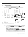
Description
3.1
3
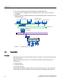
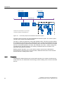
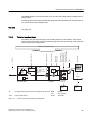
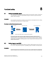
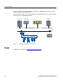
System configuration
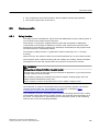
Overview
The pressure transmitter can be used in a number of system configurations.
Use with the SIMATIC PCS 7 Automation System is described below.
System communication
The Operator Station of the SIMATIC PCS 7 process control system allows easy and safe
control of the process by the operating personnel using OS Multi-Clients.
The Maintenance Station assists the maintenance engineer in guaranteeing high plant
availability, securing this long-term using optimization measures, and implementing the
maintenance measures using a minimum of personnel, materials, energy, costs etc.
The field devices are integrated over PROFIBUS PA with:
SITRANS P, Series DS III with PROFIBUS PA
Operating Instructions, 09/2012, A5E00053276-06
17
Description
3.2 Application
● PA Link to the gateway between PROFIBUS PA and PROFIBUS DP
● Control system, e.g. SIMATIC PCS 7 Automation System, which communicates over
PROFIBUS
● Engineering Station, SIMATIC PDM (Process Device Manager) which communicates over
Industrial Ethernet
Operator station
Engineering station
SIMATIC PDM clients
OS multi-clients
Maintenance station
Maintenance/
OS server
Industrial Ethernet
SIMATIC PCS 7
automation system
PROFIBUS DP
PA Link
PROFIBUS PA
Figure 3-1
3.2
Possible system configuration
Application
Overview
Depending on the version, the transmitter measures corrosive, non-corrosive and toxic gases,
vapors and liquids.
Depending on the device version, you can use the transmitter for the following types of
measurement:
● Gauge pressure
● Absolute pressure
● Differential pressure
With appropriate parameter settings and the necessary add-on parts (e.g. flow orifices and
remote seals), the pressure transmitter can also be used for the following measurements:
18
SITRANS P, Series DS III with PROFIBUS PA
Operating Instructions, 09/2012, A5E00053276-06
Description
3.2 Application
● Level
● Volume
● Mass
● Volume flow
● Mass flow
The output signal is a process-based, digital PROFIBUS PA/ Foundation™ Fieldbus FF signal.
You can install the transmitter with the type of protection "Intrinsic safety" or "Flameproof
enclosure" in hazardous areas. The devices have an EC-Type Examination Certificate, and
comply with the corresponding harmonized European directives of the CENELEC.
The transmitter is available with various designs of remote seal for special applications. A
special application, for example, is the measurement of highly viscous materials.
Gauge pressure
This version measures the gauge pressure of corrosive, non-corrosive and toxic gases, vapors
and liquids.
The smallest measuring range is 1 bar g (14.5 psi g), the largest is 700 bar g (10153 psi g).
Absolute pressure
This version measures the absolute pressure of corrosive, non-corrosive and toxic gases,
vapors and liquids.
There are two series: A "Differential pressure" series and a "Gauge pressure" series. The
"Differential pressure" series features a high overload capacity.
The smallest measuring range of the "Differential pressure" series is 250 mbar a (3.63 psi a),
the largest is 100 bar a (1450 psi a).
The smallest measuring range of the "Gauge pressure" series is 250 mbar a (3.63 psi a), the
largest is 30 bar a (435 psi a).
Differential pressure and flow rate
This version measures corrosive, non-corrosive and toxic gases, vapors and liquids. You can
use it for the following types of measurement:
● Differential pressure
● Gauge pressure, suitable for small positive or negative pressure value
● Together with a primary differential pressure device: flow q ~ ∆p
The smallest measuring range is 20 mbar (8.03 inH2O), the largest is 30 bar (435 psi).
Level
This version with mounting flange measures the level of non-corrosive, corrosive and toxic
liquids in open and closed containers. The smallest measuring range is 250 mbar (3.63 psi),
SITRANS P, Series DS III with PROFIBUS PA
Operating Instructions, 09/2012, A5E00053276-06
19
Description
3.3 Structure
the largest is 5 bar (72.5 psi). The nominal diameter of the mounting flange is DN 80 or DN
100, or 3" or 4".
For the level measurement on open containers, the low-pressure side of the measuring cell
remains open. This measurement is referred to as "Measurement against atmospheric
pressure". For the measurement on closed containers, the low-pressure side is usually
connected to the container. This balances the static pressure.
The parts wetted by the medium are made of various materials according to the corrosion
resistance required.
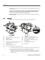
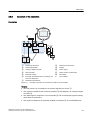
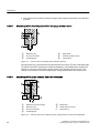
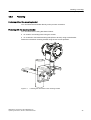
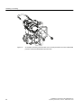
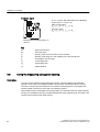
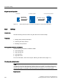
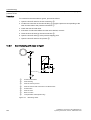
3.3
Structure
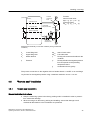
Depending on a customer-specific order, the device comprises different parts.
①
②
③
④
⑤
⑥
⑦
Key cover
Cover (front), optionally with inspection window
Display (optional)
Measuring point label
Retaining screw; twist proofing of the measuring cell
in relation to the electronics enclosure
Process connection
⑧
⑨
⑩
⑪
Cable inlet, optionally with cable gland
Cover (rear) for electrical terminal compartment
Electrical terminal compartment
Protective conductor connector/equipotential
bonding terminal
⑫
Nameplate (approval information)
⑬
Blanking plug
Nameplate (general information)
Figure 3-2
View of the transmitter: Left: Front right: Rear view
● The electronics enclosure is made of die cast aluminum or precision cast stainless steel.
● The housing has a removable circular cover at the front and the back.
● Depending on the device version, the front cover ② may be designed as an inspection
window. You can read the measured values straight off the digital display through this
inspection window.
20
SITRANS P, Series DS III with PROFIBUS PA
Operating Instructions, 09/2012, A5E00053276-06
Description
3.4 Structure of the label and approval plate
● The cable inlet ⑧ to the electrical terminal compartment is at the side; either the left or
right-hand one can be used. The unused opening is closed with a blanking plug ⑬.
● The protective conductor terminal/equipotential bonding terminal ⑪ is located at the back
of the enclosure.
● The electrical terminal compartment ⑩ for the auxiliary power and shield is accessible
when you remove the back cover ⑨.
● The measuring cell with a process connection ⑥ is located in the lower section of the
enclosure. This measuring cell is secured against twisting by a retaining screw ⑤. Thanks
to the modular structure of the transmitter, the measuring cell, the electronic unit or the
network card can be replaced if required.
● On the upper face of the enclosure you can see crosshead screws which secure the key
cover ①, under which there are 3 keys for local operation.
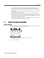
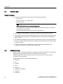
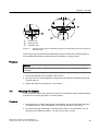
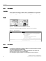
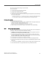
3.4
Structure of the label and approval plate
Structure of the label
The label which bears the Order No. and other important information such as design details
or technical data is present on the side of the housing.
PED : SEP
Transmitter for pressure
7MF4034-1EB10-1DA1
A01+A20+C11+C12+D08+Y01+Y15+Y16+Y20
Fab. Nr. N1LN11-004711
V:DC
9-32 V (not intr.save) PROFIBUS-PA
H
Mat.: Connec. Diaphr.
1.4404
2.4819
Measuring span
Overrange limits
Filling
Silicone oil
: - 63 bar
: -1 - 100 bar
Type of protection IP 65
①
Order number (machine-readable product
code)
Figure 3-3
②
Serial number
Example of a label
SITRANS P, Series DS III with PROFIBUS PA
Operating Instructions, 09/2012, A5E00053276-06
21
Description
3.6 Principle of operation
Structure of the approval plate
The approval plate is provided on the opposite side. The approval plate has information about
the version of the hardware and firmware.
II 1/2 G EEx ia/ib IIC/IIB T4/T5/T6
FISCO Power Supply or
From certified intrinsically safe power source
V i ≤ 24 V ; I i ≤ 380 mA ; P i ≤ 5.32 W
C i ≤ 5 nF ; L i ≤ 10 μH (PROFIBUS-PA)
):[[[[\\]]
+:[[\\]]
&RPSDWLELOLW\LGHQWLILHU
7HUPLQDOERDUGSURGXFWVWDWXV
6HULDOQXPEHU
):HGLWLRQ
)XQFWLRQUDQJHLGHQWLILHU
3URILOHUHYLVLRQ
PTB 99 ATEX 2122
Observe EC-Type Examination Certificate !
Figure 3-4
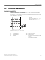
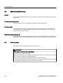
3.5
Example of an approval plate
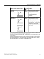
Measuring point label layout
Y01 or Y02
= max. 27 char.
Y15 = max. 16 char.
.... to .... mbar
Measuring point number (TAG No.)
Y99 = max. 10 char.
Y16 = max. 27 char.
Figure 3-5
1234
Measuring point text
Example of measuring point label
3.6
Principle of operation
3.6.1
Overview of mode of operation
This chapter describes how the transmitter works.
First the electronics are described, and then the physical principle of the sensors which are
used with the various device versions for the individual measurement types.
22
SITRANS P, Series DS III with PROFIBUS PA
Operating Instructions, 09/2012, A5E00053276-06
Description
3.6 Principle of operation
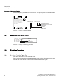
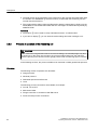
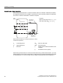
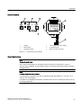
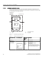
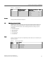
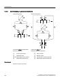
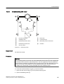
3.6.2
Operation of the electronics
Description
$
˩&
'
3$LQWHU
IDFH
((3520
(OHFWURQLFV
(OHFWURQLFV
$X[LOLDU\SRZHU
6XSSO\
XQLW
'3
3$
6HQVRU
((3520
&HOO
352),%86'3
352),%863$
%XV
PDVWHU
S
H
0HDVXULQJFHOO
①
②
③
④
⑤
⑥
⑦
Measuring cell sensor
Measuring amplifier
Analog-to-digital converter
Microcontroller
Electrical isolation
Each with an EEPROM in the measuring cell
and in the electronics
⑧
⑨
⑩
⑪
⑫
Power supply
pe
Input variable
Buttons (local operation)
Display
DP/PA coupler or DP/PA link
Bus master
PROFIBUS PA interface
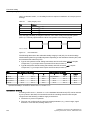
Figure 3-6
Principle of operation of the electronics with PA communication
Function
● The inlet pressure is converted into an electrical signal by the sensor ①.
● This signal is amplified by the measuring amplifier ② and digitized in an analog-to-digital
converter ③.
● The digital signal is analyzed in a microcontroller ④ and corrected with regard to linearity
and thermal characteristics.
● The signal is available at an electrically isolated PA interface ⑦ on the PROFIBUS PA.
SITRANS P, Series DS III with PROFIBUS PA
Operating Instructions, 09/2012, A5E00053276-06
23
Description
3.6 Principle of operation
● The data specific to the measuring cell, the electronics data, and the parameterization data
are stored in two EEPROMs ⑥. The first memory is linked with the measuring cell, the
second with the electronics.
● The results with the status values and diagnostics data are transmitted cyclically over the
PROFIBUS PA. Parameterization data and error messages are transmitted acyclically by
SIMATIC PDM.
Operation
● The buttons ⑧ can be used to call up individual functions, so-called modes.
● If you have a display ⑨, you can track the mode settings and other messages on it.
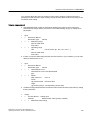
3.6.3
Principle of operation of the measuring cell
CAUTION
If the measurement signal fails because of sensor breakage, the seal diaphragm may also
be destroyed. In the worst case scenario, the process medium leaks from the reference
pressure opening in the devices used for gauge pressure with a measuring span of ≤ 63 bar.
In the following sections, the process variable to be measured is called general inlet pressure.
Overview
The following modes of operation are described:
● Gauge pressure
● Absolute pressure
● Differential pressure and flow rate
● Level
The following process connections are available, for example:
● G1/2 B, 1/2-14 NPT
● Male thread: M20
● Flange connection in accordance with EN 61518
● Flush-mounted process connections
24
SITRANS P, Series DS III with PROFIBUS PA
Operating Instructions, 09/2012, A5E00053276-06
Description
3.6 Principle of operation
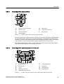
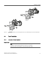
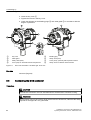
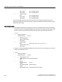
3.6.3.1
Measuring cell for gauge pressure
SH
①
②
③
④
Measuring cell
⑤
⑥
Gauge pressure sensor
Process connection
pe
Inlet pressure
Reference pressure opening
Filling liquid
Seal diaphragm
Figure 3-7
Function chart of measuring cell for gauge pressure
The inlet pressure (pe) is transferred to the gauge pressure sensor ⑥ via the seal diaphragm
④ and the fill fluid ⑤, displacing its measuring diaphragm. The displacement changes the
resistance of the four piezoresistors (bridge circuit) of the gauge pressure sensor. The change
in the resistance causes a bridge output voltage proportional to the inlet pressure.
Transmitters with measuring span ≤ 63 bar measure the inlet pressure against atmosphere,
those with measuring spans ≥ 160 bar against vacuum.
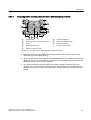
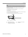
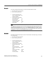
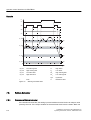
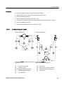
3.6.3.2
Measuring cell for differential pressure and flow rate
①
②
③
④
⑤
Inlet pressure P+
Pressure cap
O-ring
Measuring cell body
⑥
⑦
⑧
⑨
Overload diaphragm
Filling liquid
Seal diaphragm
Inlet pressure P-
Differential pressure sensor
Figure 3-8
Function chart of the measuring cell for differential pressure and flow rate
SITRANS P, Series DS III with PROFIBUS PA
Operating Instructions, 09/2012, A5E00053276-06
25
Description
3.6 Principle of operation
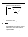
● Differential pressure is transmitted to the differential pressure sensor ⑤ through the seal
diaphragms ⑧ and the filling liquid ⑦.
● When measuring limits are exceeded, the seal diaphragm ⑧ is displaced until the seal
diaphragm ② rests on the measuring cell body ④. The differential pressure sensor ⑤ is
thus protected against overloading since no further deflection of the overload diaphragm
⑥ is possible.
● The seal diaphragm ⑧ is displaced by the differential pressure. The displacement changes
the resistance of the four piezoresistors (bridge circuit) of the differential pressure sensor.
● The change in the resistance causes a bridge output voltage proportional to the differential
pressure.
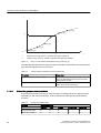
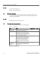
3.6.3.3
Measuring cell for level
①
②
③
④
⑤
Pressure cap
O-ring
Measuring cell body
Overload diaphragm
Differential pressure sensor
Figure 3-9
⑥
⑦
⑧
⑨
⑩
Seal diaphragm on the measuring cell
Filling liquid of the measuring cell
Capillary tube with the fill fluid of the mounting
flange
Flange with a tube
Seal diaphragm on the mounting flange
Function chart of the measuring cell for level
● The inlet pressure (hydrostatic pressure) works hydraulically on the measuring cell through
the seal diaphragm ⑩ on the mounting flange ⑩.
● Differential pressure at the measuring cell is transmitted to the differential pressure sensor
⑤ through the seal diaphragms ⑥ and the filling liquid ⑦.
● When measuring limits are exceeded, the overload diaphragm ④ is displaced until one of
the seal diaphragms ⑥ or ⑩ rests on the measuring cell body ③. The seal diaphragms
⑥ thus protect the differential pressure sensor ⑤ from overload.
● The seal diaphragm ⑥ is displaced by the differential pressure. The displacement changes
the resistance of the four doped piezoresistors in the bridge circuit.
● The change in the resistance causes a bridge output voltage proportional to the differential
pressure.
26
SITRANS P, Series DS III with PROFIBUS PA
Operating Instructions, 09/2012, A5E00053276-06
Description
3.6 Principle of operation
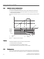
3.6.3.4
Measuring cell for absolute pressure from the differential pressure series
SH
①
②
③
④
⑤
Measuring cell filling liquid
O-ring
⑥
⑦
⑧
Measuring cell body
pe
Pressure input variable
Pressure cap
Seal diaphragm on the measuring cell
Overload diaphragm
Reference pressure
Absolute pressure sensor
Figure 3-10
Function chart of measuring cell for absolute pressure
● Absolute pressure is transmitted to the absolute pressure sensor ⑤ through the seal
diaphragm ② and the filling liquid ⑦.
● When measuring limits are exceeded, the overload diaphragm ⑥ is displaced until the seal
diaphragm ② rests on the measuring cell body ④. The seal diaphragm thus protects the
absolute pressure sensor ⑤ from overload.
● The difference between the inlet pressure (pe) and the reference pressure ⑧ on the
negative side of the measuring cell displaces the seal diaphragm ②. The displacement
changes the resistance of the four piezoresistors (bridge circuit) of the absolute pressure
sensor.
SITRANS P, Series DS III with PROFIBUS PA
Operating Instructions, 09/2012, A5E00053276-06
27
Description
3.6 Principle of operation
● The change in the resistance causes a bridge output voltage proportional to the absolute
pressure.
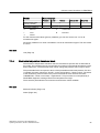
3.6.3.5
Measuring cell for absolute pressure from the gauge pressure series
SH
①
②
③
④
⑤
⑥
Measuring cell
Process connection
Seal diaphragm
Figure 3-11
Filling liquid
Absolute pressure sensor
Inlet pressure
Function chart of measuring cell for absolute pressure
The inlet pressure (pe) is transferred to the absolute pressure sensor ⑤ via the seal diaphragm
③ and the fill fluid ④, displacing its measuring diaphragm. The displacement changes the
resistance of the four piezoresistors (bridge circuit) of the absolute pressure sensor. The
change in the resistance causes a bridge output voltage proportional to the inlet pressure.
3.6.3.6
Measuring cell for gauge pressure, front-flush membrane
SH
①
②
③
④
Measuring cell
⑤
⑥
Gauge pressure sensor
Process connection
pe
Inlet pressure
Reference pressure opening
Filling liquid
Seal diaphragm
Figure 3-12
28
Function chart of the measuring cell for gauge pressure, flush mounted diaphragm
SITRANS P, Series DS III with PROFIBUS PA
Operating Instructions, 09/2012, A5E00053276-06
Description
3.6 Principle of operation
The inlet pressure (pe) is transferred to the gauge pressure sensor ⑥ via the seal diaphragm
④ and the filling liquid ⑤, displacing its measuring diaphragm. The displacement changes
the resistance of the four piezoresistors (bridge circuit) of the gauge pressure sensor. The
change in the resistance causes a bridge output voltage proportional to the inlet pressure.
Transmitters with measuring span ≤ 63 bar measure the inlet pressure against atmosphere,
those with measuring spans ≥ 160 bar against vacuum.
3.6.3.7
Measuring cell for absolute pressure, front-flush membrane
SH
①
②
③
Process connection
④
⑤
Absolute pressure sensor
Seal diaphragm
pe
Inlet pressure
Measuring cell
Figure 3-13
Filling liquid
Function chart of the measuring cell for absolute pressure, flush mounted diaphragm
The inlet pressure (pe) is transferred to the absolute pressure sensor ⑤ via the seal diaphragm
③ and the filling liquid ④, and displaces its measuring diaphragm. The displacement changes
the resistance of the four piezoresistors (bridge circuit) of the absolute pressure sensor. The
change in the resistance causes a bridge output voltage proportional to the inlet pressure.
SITRANS P, Series DS III with PROFIBUS PA
Operating Instructions, 09/2012, A5E00053276-06
29
Description
3.8 SIMATIC PDM
3.7
Remote seal
Product description
● A remote seal measuring system comprises the following elements:
– Remote seal
– Transmission line, e.g. capillary line
– Measuring device
Note
Malfunction of the remote seal measuring system
If you separate the components of the remote seal measuring system, this results in
malfunctioning of the system.
Do not separate the components under any circumstances.
● The measuring system based on a hydraulic principle is used to transfer pressure.
● The capillary line and the remote seal diaphragm are the most sensitive components in the
remote seal measuring system. The material thickness of the remote seal diaphragm is
only ∼ 0.1 mm.
● The smallest of leakages in the transmission system leads to the loss of transmission fluid.
● The loss of transmission fluid results in inaccuracies in the measurement and failure of the
measuring system.
● In order to avoid leaks and measuring errors, please observe the installation and
maintenance instructions in addition to the safety notes.
3.8
SIMATIC PDM
SIMATIC PDM is a software package for configuring, parameter assignment, commissioning,
diagnostics and maintenance of this device and other process devices.
SIMATIC PDM offers simple monitoring of process values, alarms, and device status
information of the transmitter.
SIMATIC PDM allows the process device data to be:
● displayed
● set
● modified
● saved
● diagnosed
● checked for plausibility
● managed
● simulated
30
SITRANS P, Series DS III with PROFIBUS PA
Operating Instructions, 09/2012, A5E00053276-06
Description
3.9 PROFIBUS
3.9
PROFIBUS
The Process Fieldbus (PROFIBUS) is an open communications system for automation
technology and is specified in the international standard IEC 61158.
PROFIBUS Process Automation (PROFIBUS PA) is a variant of PROFIBUS Decentral
Peripherals (PROFIBUS DP), which is widely used in process technology.
3.9.1
Transmission technology
PROFIBUS PA uses a special transmission technology, enabling it to fulfill the requirements
of process automation and process technology. This transmission technology is defined in the
international standard IEC 61158-2. The low transmission rate reduces the power loss in
comparison to PROFIBUS DP, enabling an intrinsically safe technology for use in hazardous
zones with explosive atmospheres. The PROFIBUS PA and PROFIBUS DP protocols are
identical.
3.9.2
Bus topology
The bus topology is mainly able to be selected as desired. Therefore, line, star and tree
structures, and mixed forms are possible. All types of field devices such as transmitters, actors,
analysis devices, etc. can be connected to the PROFIBUS PA.
Advantages include:
● Savings on installation costs
● More extensive diagnostics, leading to increased availability of installation sections
● Automatic management of installation documentation
● Installation optimization on the fly during operation
In an automation system, there are generally multiple PROFIBUS PA lines connected to fast
PROFIBUS DP via coupler units. This is also connected to the process control system.
Both bus systems use the same protocol layer. This makes PROFIBUS PA a "communicationscompatible" extension of the PROFIBUS DP into the field.
SITRANS P, Series DS III with PROFIBUS PA
Operating Instructions, 09/2012, A5E00053276-06
31
Description
3.9 PROFIBUS
&ODVVPDVWHU
&ODVVPDVWHU
352),%86'3
352),%863$
6ODYHV
)LHOGGHYLFHVGLVWULEXWHG,2ORZHUOHYHO
FRQWUROOHUVJDWHZD\WR352),%863$
Figure 3-14
Functional principle of the PROFIBUS automation system
The figure shows a section of a typical PROFIBUS automation system. The control system
consists of two masters with distributed tasks.
The class-1 master recognizes the control and regulation tasks. The class-2 master enables
the operating and monitoring functions. Between the class-1 master and the field devices there
is a periodic exchange of measurement and settings data. The status information from the field
devices is transmitted parallel to this data, and evaluated in the class-1 master. Assignment
of parameters for the field devices or the reading of additional device information is not
performed during periodic operation.
Besides periodic operation, one or more class-2 masters can access the field devices
asynchronously. Using this type of communication, additional information can be retrieved
from the devices or settings sent to them.
3.9.3
Properties
PROFIBUS PA allows bidirectional communication between a bus master and field devices.
At the same time, the shielded two-strand wiring provides auxiliary power to the two-wire field
devices.
32
SITRANS P, Series DS III with PROFIBUS PA
Operating Instructions, 09/2012, A5E00053276-06
Installing / mounting
4.1
4
Basic safety instructions
WARNING
Wetted parts unsuitable for the process media
Danger of injury or damage to device.
Hot, toxic and corrosive media could be released if the process medium is unsuitable for the
wetted parts.
● Ensure that the material of the device parts wetted by the process medium is suitable for
the medium. Refer to the information in "Technical data" (Page 187).
WARNING
Incorrect material for the diaphragm in Zone 0
Danger of explosion in the hazardous area. In the case of operation with intrinsically safe
supply units of category "ib" or devices of the flameproof enclosure version "Ex d" and
simultaneous use in Zone 0, transmitter explosion protection depends on the tightness of the
diaphragm.
● Ensure that the material used for the diaphragm is suitable for the process medium. Refer
to the information in the section "Technical data (Page 187)".
WARNING
Unsuitable connecting parts
Danger of injury or poisoning.
In case of improper mounting hot, toxic and corrosive process media could be released at
the connections.
● Ensure that connecting parts (such as flange gaskets and bolts) are suitable for connection
and process media.
SITRANS P, Series DS III with PROFIBUS PA
Operating Instructions, 09/2012, A5E00053276-06
33
Installing / mounting
4.1 Basic safety instructions
Note
Material compatibility
Siemens can provide you with support concerning selection of sensor components wetted
by process media. However, you are responsible for the selection of components. Siemens
accepts no liability for faults or failures resulting from incompatible materials.
WARNING
Exceeded maximum permissible operating pressure
Danger of injury or poisoning.
The maximum permissible operating pressure depends on the device version. The device
can be damaged if the operating pressure is exceeded. Hot, toxic and corrosive process
media could be released.
● Make sure that the device is suitable for the maximum permissible operating pressure of
your system. Refer to the information on the nameplate and/or in "Technical data
(Page 187)".
WARNING
Exceeded maximum ambient or process media temperature
Danger of explosion in hazardous areas.
Device damage.
● Make sure that the maximum permissible ambient and process media temperatures of
the device are not exceeded. Refer to the information in Chapter "Technical data
(Page 187)".
WARNING
Open cable inlet or incorrect cable gland
Danger of explosion in hazardous areas.
● Close the cable inlets for the electrical connections. Only use cable glands or plugs which
are approved for the relevant type of protection.
34
SITRANS P, Series DS III with PROFIBUS PA
Operating Instructions, 09/2012, A5E00053276-06
Installing / mounting
4.1 Basic safety instructions
WARNING
Incorrect conduit system
Danger of explosion in hazardous areas as result of open cable inlet or incorrect conduit
system.
● In the case of a conduit system, mount a spark barrier at a defined distance from the
device input. Observe national regulations and the requirements stated in the relevant
approvals.
See also
Technical data (Page 187)
WARNING
Incorrect mounting at Zone 0
Danger of explosion in hazardous areas.
● Ensure sufficient tightness at the process connection.
● Observe the standard IEC/EN 60079-14.
WARNING
Danger with "flameproof enclosure" protection
Danger of explosion in hazardous areas. An explosion may be caused by hot gas escaping
from the flameproof enclosure if there is too little space between it and the fixed parts.
● Ensure that there is a space of at least 40 mm between the flameproof joint and the fixed
parts.
①
Flameproof joint
SITRANS P, Series DS III with PROFIBUS PA
Operating Instructions, 09/2012, A5E00053276-06
35
Installing / mounting
4.1 Basic safety instructions
WARNING
Loss of explosion protection
Danger of explosion in hazardous areas if the device is open or not properly closed.
● Close the device as described in Chapter "PROFIBUS assembly guidelines (Page 60)".
WARNING
Use of incorrect device parts in potentially explosive environments
Devices and their associated device parts are either approved for different types of protection
or they do not have explosion protection. There is a danger of explosion if device parts (such
as covers) are used for devices with explosion protection that are not expressly suited for
this type of protection. If you do not adhere to these guidelines, the test certificates and the
manufacturer warranty will become null and void.
● Use only device parts that have been approved for the respective type of protection in the
potentially explosive environment. Covers that are not suited for the "explosion-proof" type
of protection are identified as such by a notice label attached to the inside of the cover
with "Not Ex d Not SIL".
● Do not swap device parts unless the manufacturer specifically ensures compatibility of
these parts.
CAUTION
Hot surfaces resulting from hot process media
Danger of burns resulting from surface temperatures above 70 °C (155 °F).
● Take appropriate protective measures, for example contact protection.
● Make sure that protective measures do not cause the maximum permissible ambient
temperature to be exceeded. Refer to the information in Chapter "Technical data
(Page 187)".
CAUTION
External stresses and loads
Damage to device by severe external stresses and loads (e.g. thermal expansion or pipe
tension). Process media can be released.
● Prevent severe external stresses and loads from acting on the device.
36
SITRANS P, Series DS III with PROFIBUS PA
Operating Instructions, 09/2012, A5E00053276-06
Installing / mounting
4.1 Basic safety instructions
4.1.1
Installation location requirements
WARNING
Insufficient air supply
The device may overheat if there is an insufficient supply of air.
● Install the device so that there is sufficient air supply in the room.
● Observe the maximum permissible ambient temperature. Refer to the information in the
section "Technical data (Page 187)".
CAUTION
Aggressive atmospheres
Damage to device through penetration of aggressive vapors.
● Ensure that the device is suitable for the application.
NOTICE
Direct sunlight
Increased measuring errors.
● Protect the device from direct sunlight.
Make sure that the maximum ambient temperature is not exceeded. Refer to the information
in the section Technical data (Page 187).
SITRANS P, Series DS III with PROFIBUS PA
Operating Instructions, 09/2012, A5E00053276-06
37
Installing / mounting
4.1 Basic safety instructions
4.1.2
Proper mounting
4.1.2.1
Incorrect mounting
NOTICE
Incorrect mounting
The device can be damaged, destroyed, or its functionality impaired through improper
mounting.
● Before installing ensure there is no visible damage to the device.
● Make sure that process connectors are clean, and suitable gaskets and glands are used.
● Mount the device using suitable tools. Refer to the information in Chapter "Technical
data (Page 187)", for example installation torques requirements.
CAUTION
Loss of degree of protection
Damage to device if the enclosure is open or not properly closed. The degree of protection
specified on the nameplate or in Chapter "Technical data (Page 187)" is no longer guaranteed.
● Make sure that the device is securely closed.
See also
PROFIBUS assembly guidelines (Page 60)
38
SITRANS P, Series DS III with PROFIBUS PA
Operating Instructions, 09/2012, A5E00053276-06
Installing / mounting
4.3 Installation (except level)
4.2
Disassembly
WARNING
Incorrect disassembly
The following dangers may result through incorrect disassembly:
- Injury through electric shock
- Danger through emerging media when connected to the process
- Danger of explosion in hazardous area
In order to disassemble correctly, observe the following:
● Before starting work, make sure that you have switched off all physical variables such as
pressure, temperature, electricity etc. or that they have a harmless value.
● If the device contains dangerous media, it must be emptied prior to disassembly. Make
sure that no environmentally hazardous media are released.
● Secure the remaining connections so that no damage can result if the process is started
unintentionally.
4.3
Installation (except level)
4.3.1
Installation mounting (except for level)
Requirements
Note
Compare the desired operating data with the data on the nameplate.
Please also refer to the information on the remote seal if this is fitted.
Note
Protect the transmitter against:
● Direct heat radiation
● Rapid temperature fluctuations
● Heavy contamination
● Mechanical damage
● Direct sunlight
SITRANS P, Series DS III with PROFIBUS PA
Operating Instructions, 09/2012, A5E00053276-06
39
Installing / mounting
4.3 Installation (except level)
Note
The housing may only be opened for maintenance, local operation or to make electrical
connections.
The installation location is to be as follows:
● Easily accessible
● As close as possible to the measuring point
● Vibration-free
● Within the permitted ambient temperature values
Installation configuration
The transmitter may in principle be configured above or below the pressure tapping point. The
recommended configuration depends on the medium.
Installation configuration for gases
Install the transmitter above the pressure tapping point.
Lay the pressure tubing with a constant gradient to the pressure tapping point, so that any
condensate produced can drain in the main line and thereby avoid corruption of the measured
values.
Installation configuration for vapor and liquid
Install the transmitter below the pressure tapping point.
Lay the pressure tubing with a constant gradient to the pressure tapping point so that any gas
pockets can escape in the main line.
4.3.2
Installation (except level)
Note
Damage to measuring cell
When installing the process connection of the pressure transmitter, do not rotate the housing.
Rotating the housing may damage the measuring cell.
To avoid damage to the device, tighten the threaded nuts of the measuring cell using a wrench.
Procedure
Attach the transmitter to the process connection with an appropriate tool.
40
SITRANS P, Series DS III with PROFIBUS PA
Operating Instructions, 09/2012, A5E00053276-06
Installing / mounting
4.3 Installation (except level)
4.3.3
Fastening
Fastening without the mounting bracket
You can fasten the transmitter directly on the process connection.
Fastening with the mounting bracket
You can fasten the mounting bracket as follows:
● On a wall or a mounting frame using two screws
● On a vertical or horizontal mounting tube (Ø 50 to 60 mm) using a tube bracket
Fasten the transmitter mounting bracket using the two screws provided.
Figure 4-1
Fastening the transmitter on the mounting bracket
SITRANS P, Series DS III with PROFIBUS PA
Operating Instructions, 09/2012, A5E00053276-06
41
Installing / mounting
4.3 Installation (except level)
Figure 4-2
42
An example of fastening the transmitter on the mounting bracket in the case of differential
pressure and horizontal differential pressure lines
SITRANS P, Series DS III with PROFIBUS PA
Operating Instructions, 09/2012, A5E00053276-06
Installing / mounting
4.4 "Level" installation
Figure 4-3
An example of fastening on the mounting bracket in the case of differential pressure and vertical differential
pressure lines
4.4
"Level" installation
4.4.1
Instructions for level installation
Requirements
Note
Compare the desired operating data with the data on the nameplate.
Please also refer to the information on the remote seal if this is fitted.
SITRANS P, Series DS III with PROFIBUS PA
Operating Instructions, 09/2012, A5E00053276-06
43
Installing / mounting
4.4 "Level" installation
Note
Protect the transmitter from:
● Direct heat
● Rapid temperature changes
● Severe soiling
● Mechanical damage
● Direct sunlight
Note
Select the height of the mounting flange such that the pressure transmitter is always mounted
below the lowest fill height to be measured.
The installation location is to be as follows:
● Easily accessible
● The measuring point must be as close as possible
● Vibration-free
● Within the permitted ambient temperature values
4.4.2
Installation for level
Note
Seals are required for the installation. The seals must be compatible with the medium to be
measured.
Seals are not included in the delivery.
Procedure
To install the transmitter for level, proceed as follows:
1. Attach the seal to the container's mating flange.
Ensure that the seal is centrically positioned and that it does not restrict the movement of
the flange's seal diaphragm in any way as otherwise the tightness of the process connection
is not guaranteed.
2. Screw on the transmitter's flange.
3. Observe the installation position.
44
SITRANS P, Series DS III with PROFIBUS PA
Operating Instructions, 09/2012, A5E00053276-06
Installing / mounting
4.4 "Level" installation
4.4.3
Connection of the negative pressure line
Assembly on an open container
A line is not required when taking measurements in an open container since the negative
chamber is connected with the atmosphere.
Ensure that no dirt enters the open connection ports, for example by using connection screws
with a 7MF4997-1CP bleed valve.
Formula:
Start of scale value: pMA = ρ · g · hU
Full-scale value: pME = ρ · g · hO
)XOOVFDOHYDOXH
K2
6WDUWRIVFDOHYDOXH
K8
+
Measurement assembly on an open container
hU
hO
p
Lower filling level
Upper filling level
Pressure
ΔpMA
ΔpME
ρ
g
SITRANS P, Series DS III with PROFIBUS PA
Operating Instructions, 09/2012, A5E00053276-06
Start of scale value
Full-scale value
Density of the measured medium in the
container
Acceleration due to gravity
45
Installing / mounting
4.4 "Level" installation
Assembly on a closed container
When taking measurements in a closed container without or with little condensate formation,
the negative pressure line is not filled. Lay the line in such a way that pockets of condensate
do not form. Install a condensation container if required.
6WDWLF
SUHVVXUH
Formula:
Start-of-scale value: ΔpMA = ρ · g · hU
Full-scale value: ΔpME = ρ · g · hO
*DVILOOHGORZ
SUHVVXUHOLQH
0D[LPXPOHYHO
)XOOVFDOHYDOXH
6WDUWRIVFDOHYDOXH
K2
K8
7UDQVPLWWHU
UHIHUHQFHOLQH
Measurement assembly on a closed container (no or little
condensate separation)
hU
hO
p
Lower filling level
Upper filling level
Pressure
ΔpMA
ΔpME
ρ
g
Start of scale value
Full-scale value
Density of the measured medium in the
container
Acceleration due to gravity
When taking measurements in a closed container with strong condensate formation, you must
fill the negative pressure line (mostly with the condensate of the measured medium) and install
a condensate pot. You can cut off the device using the dual pneumatic block 7MF9001-2.
46
SITRANS P, Series DS III with PROFIBUS PA
Operating Instructions, 09/2012, A5E00053276-06
Installing / mounting
4.5 "Remote seal" installation
6WDWLF
SUHVVXUH
Formula:
Start-of-scale value:
ΔpMA = g · (hU · ρ- hV · ρ')
Full-scale value:
ΔpMA = g · (hO · ρ- hV · ρ')
&RQVWDQW
FRPSDULVRQ
OHYHO
0D[LPXPOHYHO
)XOOVFDOHYDOXH
6WDUWRIVFDOHYDOXH
K2
/LTXLGILOOHG
ORZSUHVVXUHOLQH
KY
'
K8
7UDQVPLWWHU
UHIHUHQFHOLQH
-
Measurement assembly on a closed container (strong condensate
formation)
hU
hO
hV
Lower filling level
Upper filling level
Gland distance
ΔpMA
ΔpME
ρ
p
Pressure
ρ'
g
Start of scale value
Full-scale value
Density of the measured medium in the
container
Density of fluid in the negative pressure
line corresponds to the prevailing
temperature there
Acceleration due to gravity
The process connection on the negative side is a female thread 1/4-18 NPT or an oval flange.
Lay the line for the negative pressure using a seamless steel tube 12 mm x 1.5 mm.
4.5
"Remote seal" installation
4.5.1
Remote seal installation
General installation instructions
● Keep the measuring system in the factory packing until it is installed in order to protect it
from mechanical damage.
● When removing from the factory packing and installing: ensure that damage to and
mechanical deformations in the membrane are prevented.
SITRANS P, Series DS III with PROFIBUS PA
Operating Instructions, 09/2012, A5E00053276-06
47
Installing / mounting
4.5 "Remote seal" installation
● Never loosen the sealed filling screws on the remote seal and the measuring instrument.
● Do not cause damage to the remote separating membrane; scratches on the remote
separating membrane, e.g. due to sharp-edged objects, are the main starting points for
corrosion.
● Select suitable gaskets for sealing.
● Use a gasket having an adequately large inner diameter for flanging. Insert the gasket
concentrically; contact with the membrane leads to deviations in measurements.
● When using gaskets made of soft materials or PTFE: follow the guidelines of the gasket
manufacturer, especially regarding the tightening torque and setting cycles.
● At the time of installation, use suitable fastening components such as screws and nuts that
are compliant with fitting and flange standards.
● Excessive tightening of screwed joints on the process connection may displace the zero
point on the pressure transmitter.
Note
Commissioning
If a shut-off valve exists, open the shut-off valve slowly when commissioning in order to
avoid pressure surges.
Note
Permissible ambient and operating temperatures
Install the pressure measuring device such that the permissible limits of ambient and
measured medium temperatures are not overshot or undershot even with the
consideration of the effect of convection and heat radiation.
● Note the effect of temperature on the measuring accuracy.
● When selecting the remote seals, ensure that fittings and flange components have
adequate pressure-temperature resistance by selecting suitable materials and
pressure ratings. The pressure rating specified on the remote seal applies to reference
conditions according to IEC 60770.
● For the maximum permissible pressure at higher temperatures, please refer to the
standard specified on the remote seal.
Using remote seals with pressure measuring device for hazardous areas:
● When using remote seals with pressure measuring device for hazardous areas, the
permissible limits of ambient temperatures for the transmitter must not be exceeded. Hot
surfaces on the cooling section (capillaries or cooling elements) are a possible source of
ignition. Initiate suitable measures.
● When remote seals with a flame arrestor are used, the pressure measuring instrument
determines the permissible ambient temperature. In the case of potentially explosive
gaseous atmosphere, the temperature around the flame arrestor must not exceed +60 °C.
48
SITRANS P, Series DS III with PROFIBUS PA
Operating Instructions, 09/2012, A5E00053276-06
Installing / mounting
4.5 "Remote seal" installation
4.5.2
Installation of the remote seal with the capillary line
Notes
● Do not rest the measurement assembly on the capillary line.
● Do not bend capillary lines; risk of leakages and/or risk of considerable increase in the
setting time of the measuring system.
● Owing to the risk of bending and breakages, pay attention to mechanical overloads at the
joints such as capillary line-remote seal and capillary line-measuring device.
● Unwinding the excess capillary lines with a radius of at least 150 mm.
● Fasten the capillary line such that there are no vibrations.
● Permissible height differences:
– When installing the pressure measuring device above the measuring point, keep the
following in mind: the height difference of H1max. for remote seal measuring systems with
silicone, glycerin or paraffin oil filling. = 7 m must not be exceeded.
– If halocarbon oil is used as the filling liquid, this maximum height difference is only
H1max. = 4 m, see installation types A and B.
If negative overpressure is observed during measurements, reduce the permissible height
difference accordingly.
Installation type for gauge pressure and level measurements (open containers)
Installation type A
+R
Start of scale value:
pMA = ρFL * g * HU + ρoil * g * H1
Full-scale value:
pME = ρFL * g * HO + ρoil * g * H1
+
+X
+
Pressure transmitter above the
measuring point
Installation type B
SITRANS P, Series DS III with PROFIBUS PA
Operating Instructions, 09/2012, A5E00053276-06
49
Installing / mounting
4.5 "Remote seal" installation
+R
Start of scale value:
pMA = ρFL * g * HU - ρoil * g * H1
Full-scale value:
pME = ρFL * g * HO - ρoil * g * H1
+
+X
+
Pressure transmitter below the
measuring point
H1 ≤ 7 m (23 ft); with halocarbon oil as the filling liquid, only H1 ≤ 4 m(13.1 ft)
Key
pMA
pME
ρFL
ρoil
g
HU
HO
H1
Start of scale value
Full-scale value
Density of the process medium in the container
Density of the filling oil in the capillary line of the remote seal
Acceleration due to gravity
Lower filling level
Upper filling level
Distance between the container flange and the pressure transmitter
For absolute pressure measurements (vacuum), install the measuring device at least at the
height of the remote seal or below it (see installation types C).
Installation types for absolute pressure measurements (closed containers)
Installation type C1
+
Start of scale value:
pMA = pstart + ρoil * g * H1
Full-scale value:
pME = pend + ρoil * g * H1
SDEV
Installation type C2
50
SITRANS P, Series DS III with PROFIBUS PA
Operating Instructions, 09/2012, A5E00053276-06
Installing / mounting
4.5 "Remote seal" installation
SDEV
+
Pressure transmitter for absolute pressure always below the measuring point: H1 ≥ 200 mm
(7.9 inch)
Key
pMA
pME
pstart
pend
ρoil
g
H1
Start of scale value
Full-scale value
Start of scale pressure
Full scale pressure
Density of the filling oil in the capillary line of the remote seal
Acceleration due to gravity
Distance between the container flange and the pressure transmitter
Note
Effects of temperature
Keep the following instructions in mind in order to minimize keep the effects of temperature
in remote seal measuring systems with the differential pressure measuring device:
Install the device such that the positive and negative sides are symmetrical as far as ambient
effects, especially ambient temperatures, are concerned.
SITRANS P, Series DS III with PROFIBUS PA
Operating Instructions, 09/2012, A5E00053276-06
51
Installing / mounting
4.5 "Remote seal" installation
Installation type for differential pressure and flow rate measurements
Installation type D
+
+9
Start of scale value:
pMA = pstart - ρoil * g * HV
Full-scale value:
pME = pend - ρoil * g * HV
+
Key
pMA
pME
pstart
pend
ρoil
g
HV
Start of scale value
Full-scale value
Start of scale pressure
Full scale pressure
Density of the filling oil in the capillary line of the remote seal
Acceleration due to gravity
Gland distance
Installation types for level measurements (closed containers)
Installation type E
Start of scale value:
pMA = ρFL * g * HU - ρoil * g * HV
Full-scale value:
pME = ρFL * g * HU - ρoil * g * HV
+9
+
+2
+8
52
SITRANS P, Series DS III with PROFIBUS PA
Operating Instructions, 09/2012, A5E00053276-06
Installing / mounting
4.5 "Remote seal" installation
Key
pMA
pME
ρFL
ρoil
g
HU
HO
HV
Start of scale value
Full-scale value
Density of the process medium in the container
Density of the filling oil in the capillary line of the remote seal
Acceleration due to gravity
Lower filling level
Upper filling level
Gland distance
Installation type G
+
+9
+
+
H1 ≤ 7 m (23 ft), for halocarbon oil, however only H1
≤ 4 m (13.1 ft)
Start of scale value:
pMA = ρFL * g * HU - ρoil * g * HV
Full-scale value:
pME = ρFL * g * HO - ρoil * g * HV
+R
+X
Pressure transmitter for differential
pressure above the upper measuring
point, no vacuum
Installation type H
Start of scale value:
pMA = ρFL * g * HU - ρoil * g * HV
Full-scale value:
pME = ρFL * g * HO - ρoil * g * HV
+
+
Below the lower measuring point
SITRANS P, Series DS III with PROFIBUS PA
Operating Instructions, 09/2012, A5E00053276-06
53
Installing / mounting
4.6 Turing the measuring cell against housing
Installation type J
H2 ≤ 7 m (23 ft); with halocarbon oil as the filling
liquid, only H2 ≤ 4 m(13.1 ft)
Start of scale value:
pMA = ρFL * g * HU - ρoil * g * HV
Full-scale value:
pME = ρFL * g * HO - ρoil * g * HV
+
+
Between the measuring points, no
vacuum
Key
pMA
pME
ρFL
ρoil
g
HU
HO
HV
4.6
Start of scale value
Full-scale value
Density of the process medium in the container
Density of the filling oil in the capillary line of the remote seal
Acceleration due to gravity
Lower filling level
Upper filling level
Gland distance
Turing the measuring cell against housing
Description
You can turn the measuring cell against the housing. Turning simplifies the transmitter
operation in the case of an angled installation environment. The buttons and the current
connection can thus also be operated for an external measuring device. The display also
remains visible in enclosure covers with an inspection window.
Only limited turning is permissible! The turning range ① is marked at the foot of the electronic
housing. An orientation mark ③ is provided at the throat of the measuring cell. This mark must
remain in the marked section when turning.
54
SITRANS P, Series DS III with PROFIBUS PA
Operating Instructions, 09/2012, A5E00053276-06
Installing / mounting
4.7 Rotating the display
①
②
③
Turning range
Retaining screw
Orientation mark
Figure 4-4
Example: turning range of transmitters for pressure and absolute pressure from the gauge
pressure series
The turning range for transmitters for differential pressure and flow rate, absolute pressure
from the differential pressure series and level is identified in a similar manner.
Procedure
NOTICE
Follow the turning range, otherwise electrical connections of the measuring cell may get
damaged.
1. Loosen the retaining screw ② (Allen screw 2.5 mm).
2. Turn the electronic housing against the measuring cell. Follow the marked turning range
① while doing so.
3. Tighten the retaining screw (torque: 3.4 to 3.6 Nm).
4.7
Rotating the display
You can rotate the display in the electronics enclosure. This makes it easier to read the display
if the device is not being operated in a vertical position.
Procedure
1. Unscrew the cover of the electrical cable compartment. See section Structure (Page 20).
An identification text "FIELD TERMINAL" is provided at the side of the housing.
2. Unscrew the display. Depending on the application position of the transmitter, you can
reinstall it at four different positions. You can turn it by ±90° or ±180°.
SITRANS P, Series DS III with PROFIBUS PA
Operating Instructions, 09/2012, A5E00053276-06
55
Installing / mounting
4.7 Rotating the display
3. Screw the covers back on as far as they will go.
4. Secure the covers with the cover catch.
56
SITRANS P, Series DS III with PROFIBUS PA
Operating Instructions, 09/2012, A5E00053276-06
Connecting up
5.1
Basic safety instructions
5.1.1
Unsuitable cables and/or cable glands
5
WARNING
Unsuitable cables and/or cable glands
Danger of explosion in hazardous areas.
● Only use suitable cables and cable glands complying with the requirements specified in
Chapter "Technical data (Page 187)".
● Tighten the cable glands in accordance with the torques specified in Chapter "Technical
data (Page 187)".
● When replacing cable glands use only cable glands of the same type.
● After installation check that the cables are seated firmly.
WARNING
Hazardous contact voltage in versions with 4-conductor extension
Danger of electrocution in case of incorrect connection.
● For the electrical connection, refer to the information in Chapter "Technical data
(Page 187)".
WARNING
Improper power supply
Danger of explosion in hazardous areas as result of incorrect power supply, e.g. using direct
current instead of alternating current.
● Connect the device in accordance with the specified power supply and signal circuits. The
relevant specifications can be found in the certificates, in Chapter "Technical data
(Page 187)" or on the nameplate.
SITRANS P, Series DS III with PROFIBUS PA
Operating Instructions, 09/2012, A5E00053276-06
57
Connecting up
5.1 Basic safety instructions
WARNING
Unsafe extra-low voltage
Danger of explosion in hazardous areas due to voltage flashover.
● Connect the device to an extra-low voltage with safe isolation (SELV).
WARNING
Lack of equipotential bonding
Danger of explosion through compensating currents or ignition currents through lack of
equipotential bonding.
● Ensure that the device is potentially equalized.
Exception: It may be permissible to omit connection of the equipotential bonding for devices
with type of protection "Intrinsic safety Ex i".
WARNING
Unprotected cable ends
Danger of explosion through unprotected cable ends in hazardous areas.
● Protect unused cable ends in accordance with IEC/EN 60079-14.
WARNING
Improper laying of shielded cables
Danger of explosion through compensating currents between hazardous area and the nonhazardous area.
● Only ground shielded cables that run into the hazardous area at one end.
● If grounding is required at both ends, use an equipotential bonding conductor.
58
SITRANS P, Series DS III with PROFIBUS PA
Operating Instructions, 09/2012, A5E00053276-06
Connecting up
5.1 Basic safety instructions
WARNING
Connecting device in energized state
Danger of explosion in hazardous areas.
● Connect devices in hazardous areas only in a de-energized state.
Exceptions:
● Circuits of limited energy may also be connected in the energized state in hazardous areas.
● Exceptions for type of protection "Non-sparking nA" (Zone 2) are regulated in the relevant
certificate
WARNING
Incorrect selection of type of protection
Danger of explosion in areas subject to explosion hazard.
This device is approved for several types of protection.
1. Decide in favor of one type of protection.
2. Connect the device in accordance with the selected type of protection.
3. In order to avoid incorrect use at a later point, make the types of protection that are not
used permanently unrecognizable on the nameplate.
NOTICE
Ambient temperature too high
Damage to cable sheath.
● At an ambient temperature ≥ 60 °C (140 °F), use heat-resistant cables suitable for an
ambient temperature at least 20 °C (68 °F) higher.
NOTICE
Incorrect measured values with incorrect grounding
The device must not be grounded via the "+" connection. It may otherwise malfunction and
be permanently damaged.
● If necessary, ground the device using the "-" connection.
SITRANS P, Series DS III with PROFIBUS PA
Operating Instructions, 09/2012, A5E00053276-06
59
Connecting up
5.2 Connecting the device
Note
Electromagnetic compatibility (EMC)
You can use this device in industrial environments, households and small businesses.
For metal housings there is an increased electromagnetic compatibility compared to highfrequency radiation. This protection can be increased by grounding the housing, see Chapter
"PROFIBUS assembly guidelines (Page 60)".
5.2
Connecting the device
5.2.1
PROFIBUS assembly guidelines
Further information on PROFIBUS and PROFINET can be found on the Internet "PI
PROFIBUS - PROFINET (http://www.profibus.com/home/)" > DOWNLOADS under
"Installation guidelines".
Opening the device
1. Unscrew the cover of the electrical cable compartment. An identification text "FIELD
TERMINAL" is provided at the side of the housing.
Procedure
1. Insert the connecting cable through the cable gland ②.
2. Connect the device to the plant with the protective conductor connection ⑥.
60
SITRANS P, Series DS III with PROFIBUS PA
Operating Instructions, 09/2012, A5E00053276-06
Connecting up
5.2 Connecting the device
3. Connect the wires to the terminals "+" and "-" ③.
The device is not polarity sensitive.
4. If necessary, ground the shield to the screw of the ground terminal ⑧. The ground terminal
is electrically connected to the external protective conductor connection.
①
②
③
④
⑤
⑥
⑦
⑧
PROFIBUS PA/Foundation™ Fieldbus FF
Cable entry for auxiliary power/analog output
Connecting terminals
Test connector for direct current measuring device or connection for external display
Cover safety catch
Protective conductor connector/equipotential bonding terminal
Process connection
Grounding terminal
Figure 5-1
Electrical connection, power supply
Closing the device
1. Screw the covers ④⑦ back on as far as they will go.
2. Secure each cover with the cover catch ③⑥.
SITRANS P, Series DS III with PROFIBUS PA
Operating Instructions, 09/2012, A5E00053276-06
61
Connecting up
5.3 Connecting the M12 connector
3. Close the key cover ①.
4. Tighten the screws in the key cover.
5. Check the tightness of the blanking plugs ⑤ and cable gland ② in accordance with the
degree of protection.
8
①
②
③
④
Key cover
Cable gland
Safety catch (back)
Cover (rear) for electrical terminal compartment
Figure 5-2
⑤
⑥
⑦
⑧
Blanking plug
Safety catch (front)
Cover (front), optionally with inspection window
Safety catch for stainless steel enclosure
View of the transmitter: Left: Back right: Front view
See also
Structure (Page 20)
5.3
Connecting the M12 connector
Procedure
CAUTION
A conductive connection must not exist between the shield and the connector housing.
WARNING
The connector may only be used for Ex ia devices and non-Ex devices; otherwise the safety
required for the approval is not guaranteed.
62
SITRANS P, Series DS III with PROFIBUS PA
Operating Instructions, 09/2012, A5E00053276-06
Connecting up
5.3 Connecting the M12 connector
Note
Observe the protection class of the M12 connector when defining the protection class.
For devices in which a connector is already available on the housing, the connection is
established using a cable jack.
1. Thread the parts of the cable jack as described by the connector manufacturer.
2. Strip approximately 18 mm of the bus cable ①.
3. Twist the shield.
4. Thread the shield in the insulating sleeve.
5. Draw 8 mm of shrink sleeve over the cable, wires and shield up to the reference edge ②.
6. Screw the cable ends and the shield in the pin insert.
7. Fix the parts of the cable jack as described by the connector manufacturer.
Figure 5-3
①
②
Preparing the connecting cable
Reference edge for stripping
Reference edge for the dimension
specifications for cable assembly
SITRANS P, Series DS III with PROFIBUS PA
Operating Instructions, 09/2012, A5E00053276-06
③
④
Insulating sleeve over the shield
Shrink sleeve
63
Connecting up
5.3 Connecting the M12 connector
Pin assignment
Layout for M12 connector
①
②
1
2
3
4
64
M12 x 1 thread
Positioning catch
+
Not connected
Shield
Layout for M12 jack
①
Positioning slot
1
2
3
4
+
Not connected
Shield
Middle jack contact not connected
SITRANS P, Series DS III with PROFIBUS PA
Operating Instructions, 09/2012, A5E00053276-06
6
Operation
6.1
Overview of operation
Introduction
The following description provides an overview of the operating functions which can be
executed with the pressure transmitter and the safety information which is to be observed when
doing so. You can operate the transmitter locally and over PROFIBUS. Local operation will be
described first, and then the operating functions over PROFIBUS.
Chapter contents:
● Basic safety instructions (Page 66)
● Information on operation (Page 66)
● Display (Page 67)
● Local operation (Page 70)
Overview of operating functions
You can operate the basic settings of the pressure transmitter using the buttons on the device.
The entire range of settings can be operated via PROFIBUS.
The following table describes the basic operating functions offered by a device with display.
Table 6-1
Operating functions
Function
With buttons
Over PROFIBUS
Electrical damping
Yes
Yes
Zero point calibration (position correction)
Yes
Yes
Key lock and write protection
Yes
Yes
Measured value display
Yes
Yes
Unit
Yes
Yes
Bus address
Yes
Yes
Device mode
Yes
Yes
Decimal point
Yes
Yes
Zero point drift
Yes
Yes
LO calibration
Yes
Yes
HI calibration
Yes
Yes
Customized characteristic curve
No
Yes
Diagnostics function
No
Yes
Measurement type
No
Yes
SITRANS P, Series DS III with PROFIBUS PA
Operating Instructions, 09/2012, A5E00053276-06
65
Operation
6.3 Information on operation
Further operating functions are accessible via PROFIBUS for special applications.
6.2
Basic safety instructions
Note
Incorrect reproduction of the process pressure
If you have changed the basic functions of the pressure transmitter, the display and the
measurement output could be set such that the actual process pressure is not reproduced.
Therefore, check the basic parameters before commissioning.
6.3
Information on operation
The following rules apply to operation of the pressure transmitter:
● The device always increments numerical values in steps from the displayed digit of least
significance.
If you press the button longer, it increments the next displayed digit of higher significance.
This procedure can be used for fast coarse setting over a wide numerical range. For the
fine adjustment, release the [↑] or [↓] button again. Then press the button again.
Violations of the measured value limits are output on the display by
or .
● If you wish to operate the device using the buttons, the lock must be canceled.
● If you are operating the transmitter locally, write operations over PROFIBUS are rejected
during this time.
It is possible to read data at any time, e.g. measured values.
Note
If you allow more than 2 minutes to pass following the pressing of a button, the setting is
saved and the measured-value display is returned to automatically.
The operating instructions in the Chapter "Local operation (Page 70)" apply if the device has
been delivered with a dummy cover.
66
SITRANS P, Series DS III with PROFIBUS PA
Operating Instructions, 09/2012, A5E00053276-06
Operation
6.4 Display
6.4
Display
6.4.1
Display elements
Structure
①
②
③
④
Measured value
Unit/bar graph
Root display
Mode/button lock
Figure 6-1
⑤
⑥
⑦
⑧
Violation of lower limit
Symbol for measured value
Violation of higher limit
Communication display
Display layout
Description
The display is used for the local display of the measured value ① with:
● Unit ②
● Mode ④
● Sign ⑥
● Statuses ⑤ and ⑦
The display ① outputs the measured value in a physical unit ② which can be selected by the
customer.
The Violation of lower limit ⑤ and Violation of upper limit ⑦ displays are also referred to as
status since they have meanings dependent on the settings.
If the communication display ⑧ blinks, this indicates an active communication.
SITRANS P, Series DS III with PROFIBUS PA
Operating Instructions, 09/2012, A5E00053276-06
67
Operation
6.4 Display
6.4.2
Units display
Description
The unit display comprises five 14-segment fields for representing the unit as a percentage
value or physical unit. A bar graph showing the percentage measured value range from 0 to
100% can be displayed as an alternative to the unit. The bar graph function is disabled by
default.
Display
Figure 6-2
Examples of measured-value display and bar graph
The following messages may appear as a ticker in the bottom line of the display.
Table 6-2
Message as ticker
Ticker
Meaning
"DIAGNOSTIC WARNING"
Is always displayed if:
● An event configured by the user is to be signaled with a
warning. For example:
–
Limit reached
–
Event counter for limit values exceeded
–
Calibration time expired
● The status of one of the device variables is "UNCERTAIN".
"SIMULATION"
6.4.3
Is always displayed when the simulation of a pressure value or
temperature value is active.
Error display
Description
If hardware faults, software errors or diagnostic alarms occur in the transmitter, the message
"Error" appears in the measured value display.
A status code indicating the type of error appears in the bottom line of the display. This
diagnostic information is also available via PROFIBUS.
Error messages are displayed for about 10 seconds after the occurrence of the error.
68
SITRANS P, Series DS III with PROFIBUS PA
Operating Instructions, 09/2012, A5E00053276-06
Operation
6.4 Display
Display
Figure 6-3
Example of error message
See also
Overview of status codes (Page 181)
6.4.4
Mode display
Description
The selected active mode is shown in the mode display.
Display
Figure 6-4
Example for mode display
In the example, a damping of 0.2 seconds was set in mode 4.
6.4.5
Status display
Description
The arrows of the status display have a different meaning depending on the mode setting. The
table below shows the meanings of the arrows in the respective functions.
SITRANS P, Series DS III with PROFIBUS PA
Operating Instructions, 09/2012, A5E00053276-06
69
Operation
6.5 Local operation
Meaning
Table 6-3
Meaning of the arrow displays
Function
Mode
Measured value display
Display
Display
Pressure exceeds the upper
sensor limit.
Pressure falls below the lower
sensor limit.
Adjusting damping
4
Exceeds the upper damping
value
Falls below the lower damping
value
LO calibration
19
–
Calibration span too low
HI calibration
20
Calibration span too high
–
Alarm
Upper alarm limit reached
Lower alarm limit reached
Warning
Upper warning limit reached
Lower warning limit reached
See also
Overview of status codes (Page 181)
6.5
Local operation
6.5.1
Control elements for local operation
Introduction
You operate the transmitter on site using the buttons. You can select and execute the functions
described in the table using adjustable modes. Operation by buttons is not available for devices
without display.
70
SITRANS P, Series DS III with PROFIBUS PA
Operating Instructions, 09/2012, A5E00053276-06
Operation
6.5 Local operation
Control elements
➀
Display
➁
Connecting plug for the display
➂
Mode button
➃
Increment button
➄
Decrement button
➅
Button symbols (see cap)
Figure 6-5
Position of keys and display
Operating functions
Note
Zero point calibration
In the case of transmitters for absolute pressure, the start of scale value is vacuum!
The zero point calibration for transmitters which do not measure absolute pressure results in
maladjustments.
Note
Locking of buttons and functions
Local operation is possible if you are in measuring mode and neither "L", "LA" nor "LL" is
output in the mode display.
If operations are disabled, parameters can still be read. An error message is output if you try
to change parameters.
SITRANS P, Series DS III with PROFIBUS PA
Operating Instructions, 09/2012, A5E00053276-06
71
Operation
6.5 Local operation
Table 6-4
Operating functions using buttons
Function
Measured value
Mode
Button function
[M]
[↑]
[↓]
Display, explanations
[↑] and [↓]
Here you
can
select the
modes.
The current measured value is displayed as
you have set it in the function "Measuredvalue display, mode 13".
Error display
Electrical damping
Zero point calibration
(position correction)
Error
4
7
A fault exists.
Increase
damping
Decrease Set to 0
d
damping
Time constant T63 in seconds
Increase
correctio
n value
Decrease Apply
Vent transmitter for gauge pressure,
differential pressure, flow or level.
correctio
n value
Range of adjustment: 0.0 s to 100.0 s
Evacuate transmitter for absolute pressure (<
0.1 ‰ of span).
Measured value in pressure unit
Locking of buttons and
functions
10
Change
Cancel 5 s *)
L
Locking of buttons and functions
(hardware write protection); local
operation disabled
LC
Write blocking; local operation
possible
LA
Enabling of local operation
LL
Combination of write blocking and no
enabling of local operation
*) Does not apply to "Safe (PROFIsafe)
mode". In this case, refer to the information in
Chapter "PROFIsafe (Page 129)".
Measured value display 13
Select from various
possibilities.
–
Selection of various variables
Unit
14
Select from table for
measured value
display.
First value in
each case
from the
physical unit
table
Physical unit
Bus address
15
Increase
Operating mode of
device,
see also Device
operation type
(Page 82)
16
Change
Decrease
Node address on the PROFIBUS
Value between 0 and 126
Selection of operating mode of device
● Profile-compatible 1 AI
● Profile-compatible with extensions
● Old SITRANS P/PA device
● Profile-compatible 1 AI, 1 TOT
Decimal point
17
Zero point adjustment
18
LO calibration
19
Increase
value
Decrease Apply
value
Calibrate bottom point of characteristic
HI calibration
20
Increase
value
Decrease Apply
value
Calibrate top point of characteristic
72
To left
To right
Position of decimal point in display
Display of current measuring range
SITRANS P, Series DS III with PROFIBUS PA
Operating Instructions, 09/2012, A5E00053276-06
Operation
6.5 Local operation
6.5.2
Operation using buttons
Introduction
This overview informs you about the most important safety notes to be observed when
operating the pressure transmitter. Furthermore, the overview guides you in adjusting the
operating functions on site.
Condition
The keyboard must have been unlocked in order to operate the device using the buttons.
Procedure
In the default setting, the device is in the measured value display.
To adjust the operating functions, proceed as follows:
1. Loosen both the screws of the keyboard cover and lift it upwards.
2. Keep pressing the [M] button until the desired mode is displayed.
3. Keep pressing the [↑] or [↓] button until the desired value is displayed.
4. Press the [M] button.
Now you have saved the values and the device goes to the next mode.
5. Close the keyboard cover using the two screws.
Note
The setting is saved and the measured values are automatically displayed again if more
than two minutes have passed after a button was pressed for the last time.
6.5.3
Setting/adjusting electrical damping
Difference between setting and adjusting
You can set or adjust the time constant of electrical damping using the buttons. Setting means
that the time constant is automatically set to 0 seconds. Adjusting means that the time constant
is adjusted between 0 and 100 seconds using the steps of 0.1 seconds. This electrical damping
also has an effect on the built-in basic damping of the device.
Condition for "setting"
You are familiar with the correct operation of the transmitter and the associated safety notes.
SITRANS P, Series DS III with PROFIBUS PA
Operating Instructions, 09/2012, A5E00053276-06
73
Operation
6.5 Local operation
Setting electrical damping
To set electrical damping to 0 seconds, proceed as follows:
1. Set mode 4.
2. Press the [↑] and [↓] buttons simultaneously.
3. Save with the [M] button.
Result
Electrical damping has been set to 0 seconds.
Condition for "adjusting"
The default setting of steps is an interval of 0.1 seconds. If you press the [↑] or [↓] button for
a longer time, the step is increased.
Adjusting electrical damping
To adjust electrical damping, proceed as follows:
1. Set mode 4.
2. Adjust the desired damping.
3. Save with the [M] button.
Result
Electrical damping has been set to the desired time constant.
See also
Operation using buttons (Page 73)
Electrical damping (Page 110)
6.5.4
Calibrate zero point
Introduction
You can calibrate the zero point in mode 7. A zero point calibration is used to correct zero
errors resulting from the mounting position of the transmitter. You must proceed differently
depending on the device version.
Requirement
You are familiar with the correct operation of the transmitter and the associated safety notes.
74
SITRANS P, Series DS III with PROFIBUS PA
Operating Instructions, 09/2012, A5E00053276-06
Operation
6.5 Local operation
Zero point calibration for gauge pressure transmitter
To calibrate the zero point, proceed as follows:
1. Pressurize the transmitter.
2. Set mode 7.
3. Press the [↑] und [↓] buttons simultaneously for 2 seconds.
4. Save with the [M] button.
Zero point calibration for absolute pressure transmitter
Note
You need a reference pressure known to you which lies within the measuring limits.
To calibrate the zero point, proceed as follows:
1. Create the reference pressure.
2. Set mode 7.
3. Set the reference pressure on the display.
4. Save with the [M] button.
6.5.5
Locking of buttons and functions
Introduction
In mode 10 you can lock the functions which are always possible using the buttons. An example
of locking is the saving of stored parameter settings.
Requirement
Note
Check the measured value display to establish that this indicates the desired setting.
Activation of locking of buttons and functions
To lock the buttons, proceed as follows:
1. Set mode 10.
2. Activate the locking of buttons and functions.
3. Save with the [M] button.
"L" is output in the mode display.
SITRANS P, Series DS III with PROFIBUS PA
Operating Instructions, 09/2012, A5E00053276-06
75
Operation
6.5 Local operation
Deactivate the locking of buttons and functions
To unlock the buttons, proceed as follows:
1. Set mode 10.
2. Press the [↑] und [↓] buttons simultaneously for 5 seconds.
Locking of the buttons and functions is now deactivated.
"- -" is output in the mode display.
See also
Key lock and write protection (Page 110)
6.5.6
Measured value display
Introduction
In mode 13, select a variable which represents the source of the measured value display. The
variable is based on the measurement type set at the factory or over the bus. The measurement
type cannot be set locally.
The measurement type options available can be set in SIMATIC PDM using the "transmitter
type" parameter. Find the following values under this parameter:
● Pressure
● Flow, not relevant for relative and absolute pressure
● Level
● Volume
Procedure
To select the source for the measured value display, proceed as follows:
1. Set mode 13.
2. Select the variable.
3. Save with the [M] button.
76
SITRANS P, Series DS III with PROFIBUS PA
Operating Instructions, 09/2012, A5E00053276-06
Operation
6.5 Local operation
Parameter
The following tables give the meaning of the variables, depending on the value of the
"transmitter type" parameter. This allows you to select the units available in mode 14.
Table 6-5
Measurement type "Absolute pressure", "Differential pressure" and "Pressure"
Source of measured value display
Variable
Available unit
OUT
(P)
Pressure
(U)
User specific
From analog input function block:
[0] : Output :
From pressure transducer block:
[1] : Secondary variable 1
SEC 1
(P)
Pressure
[2] : Measurement value (primary
variable)
PRIM
(P)
Pressure
[3] : Sensor temperature
TMP S
(T)
Temperature
[4] : Electronics temperature
TMP E
(T)
Temperature
[7] : Raw pressure value
SENS
(P)
Pressure
Variable
Available unit
OUT
(L)
Level
(U)
User specific
Table 6-6
Measurement type "Flow"
Source of measured value display
From analog input function block:
[0] : Output
From pressure transducer block:
[1] : Secondary variable 1
SEC 1
(P)
Pressure
[2] : Measurement value (primary
variable)
PRIM
(L)
Level
[3] : Sensor temperature
TMP S
(T)
Temperature
[4] : Electronics temperature
TMP E
(T)
Temperature
[5] : Secondary variable 3:
SEC 3
(M)
Mass flow
[7] : Raw pressure value
SENS
(P)
Pressure
TOTAL
(V)
Volume
(ΣM) *)
Total mass flow
From totalizer function block:
[6] : Totalizer output
Flow not relevant for relative and
absolute pressure
*) The option of selecting the physical unit is additionally determined by the channel setting (mass or
volume) of the analog input and totalizer function blocks.
SITRANS P, Series DS III with PROFIBUS PA
Operating Instructions, 09/2012, A5E00053276-06
77
Operation
6.5 Local operation
Table 6-7
Measurement type "Level (height)"
Source of measured value display
Variable
Available units
OUT
(L)
Level
(U)
User specific
From analog input function block:
[0] : Output
From pressure transducer block:
[1] : Secondary variable 1
SEC 1
(P)
Pressure
[2] : Measurement value (primary
variable)
PRIM
(L)
Level
[3] : Sensor temperature
TMP S
(T)
Temperature
[4] : Electronics temperature
TMP E
(T)
Temperature
Table 6-8
Measurement type "Level (volume)"
Source of measured value display
Variable
Available units
OUT
(V)
Volume
(U)
User specific
From analog input function block:
[0] : Output
From pressure transducer block:
[1] : Secondary variable 1
SEC 1
(P)
Pressure
[2] : Measurement value (primary
variable)
PRIM
(V)
Volume
[3] : Sensor temperature
TMP S
(T)
Temperature
[4] : Electronics temperature
TMP E
(T)
Temperature
See also
Block model for collection and processing of measured values (Page 89)
Pressure transducer block (transducer block 1) (Page 92)
6.5.7
Unit
Introduction
In mode 14, set the physical unit in which the device's measured value display should be
represented.
Requirement
You have already selected the desired source for the measured value display in mode 13.
78
SITRANS P, Series DS III with PROFIBUS PA
Operating Instructions, 09/2012, A5E00053276-06
Operation
6.5 Local operation
Procedure
To adjust the physical unit, proceed as follows:
1. Set mode 14.
The physical unit used appears in the bottom line of the display.
2. Select a unit.
3. Save with the [M] button.
The following tables show the physical units available in each measurement type.
Units
Table 6-9
Unit for pressure (P)
Unit
Display
Unit
Display
Pa
Pa
g/cm²
G/cm2
MPa
MPa
kg/cm²
KGcm2
kPa
KPa
inH2O
INH2O
hPa
hPa
inH2O(4°C)
INH2O
bar
bar
mmH2O
mmH2O
mbar
mbar
mmH2O(4°C)
mmH2O
torr
Torr
ftH2O
FTH2O
atm
ATM
inHg
IN HG
psi
PSI
mmHg
mm HG
Display
Table 6-10
Unit for volume (V)
Unit
Display
Unit
m
dm3
m3
ft
3
FT3
dm3
yd3
Yd3
cm3
cm3
pint (US)
Pint
mm3
mm3
quart (US)
Quart
l
L
US gallon
GAL
cl
cL
imp. gallon
ImGAL
ml
mL
bushel
BUSHL
hl
hL
barrel
bbl
in3
IN3
barrel liquid
bblli
3
SITRANS P, Series DS III with PROFIBUS PA
Operating Instructions, 09/2012, A5E00053276-06
79
Operation
6.5 Local operation
Table 6-11
Unit for volume flow (F)
Unit
Display
Unit
Display
m / second
m3/S
ft / hour
FT3/H
m3 / minute
m3/M
ft3 / day
FT3/D
m / hour
m3/H
Gallons / second
Gal/S
m3 / day
m3/D
Gallons / minute
Gal/M
Liters / second
L/S
Gallons / hour
Gal/H
Liters / minute
L/M
Gallons / day
Gal/D
Liters / hour
L/H
British barrel liquid /
second
bbl/S
Liters / day
L/D
British barrel liquid /
minute
bbl/M
Millions of liters / day
ml/D
British barrel liquid /
hour
bbl/H
ft3 / second
FT3/S
British barrel liquid / day bbl/D
ft / minute
FT3/M
3
3
3
Table 6-12
Unit for mass flow (M)
Unit
Display
Unit
Display
g/s
G/S
Pound / s
P/S
g / min
G/MIN
Pound / min
lb/M
g/h
G/H
Pound / h
lb/H
g/d
G/D
Pound / d
lb/D
Kg / s
KG/S
Short tons / s
ST/S
Kg / min
KG/M
Short tons / min
ST/m
Kg / h
KG/H
Short tons / h
ST/h
Kg / d
KG/D
Short tons / d
ST/d
T/s
T/S
Long tons / s
LT/s
T / min
T/M
Long tons / m
LT/m
T/h
T/H
Long tons / h
LT/h
T/d
T/D
Long tons / d
LT/d
Table 6-13
80
3
Unit for level (L)
Unit
Display
Unit
Display
m
m
ft
FT
cm
cm
in
IN
mm
mm
yd
Yd
SITRANS P, Series DS III with PROFIBUS PA
Operating Instructions, 09/2012, A5E00053276-06
Operation
6.5 Local operation
Table 6-14
Unit for mass (M)
Unit
Display
Unit
Display
kg
KG
lb
lb
g
G
STon
STon
t
T
LTon
LTon
oz
oz
Table 6-15
Unit for temperature (T)
Unit
Display
Unit
Display
K
K
°F
°F
°C
°C
°R
°R
Table 6-16
Unit for user-specific (U)
Unit
Display
arbitrary
Max. 16 characters,
If more than 5 characters, the display shows the unit as a ticker.
The input of the characters to be displayed can only be performed through the
PROFIBUS.
%
%
Note
The profile allows a much larger number of possible units. There is no limitation on some
physical values special to the output of the analog input function block. For instance, if you
have selected a unit with SIMATIC PDM which does not appear in the corresponding valid
list, the current measurement value will be shown without a unit in the measured value display.
See also
Units of the pressure transducer block (Page 96)
6.5.8
Bus address
Introduction
The node address of the device on the PROFIBUS, the so-called bus address, is set in mode
15. The permissible range runs from 0 to 126.
Note
Do not change the bus address of the device while your system is running. The device will
then no longer be visible from the application program.
SITRANS P, Series DS III with PROFIBUS PA
Operating Instructions, 09/2012, A5E00053276-06
81
Operation
6.5 Local operation
Procedure
To change the bus address, proceed as follows:
1. Set mode 15.
The currently set bus address of the device appears in the measured value display.
2. Select the bus address within the permissible range.
3. Save with the [M] button.
6.5.9
Device operation type
Introduction
Set the device mode to mode 16.
The device mode [1] is preset on the pressure transmitter. Other device modes are only suitable
if you have set another operation type through PROFIBUS.
Table 6-17
Device mode
Display
Meaning
[0]
Profile-compliant:
Exchangeable for transmitters with PROFIBUS PA Profile 3.0, with analog input function
block, without totalizer
[1]
Delivery state
Profile-compatible with extensions:
Full functionality of the SITRANS P with:
● Analog input function block
● Totalizer
[2]
Exchangeable for previous SITRANS P/PA device
[128]
Profile-compliant:
Exchangeable for transmitter with PROFIBUS PA Profile 3.0 with:
● Analog input function block
● Totalizer.
82
SITRANS P, Series DS III with PROFIBUS PA
Operating Instructions, 09/2012, A5E00053276-06
Operation
6.5 Local operation
Procedure
To change the device mode, proceed as follows:
1. Set mode 16.
The current operation type "0", "1", "2" or "128" appears in the measured value display.
2. Select the device mode.
The local operation type must match the operation type in PROFIBUS.
3. Save with the [M] button.
Note
Each device operation type is assigned a particular device master data file (GSD file).
If the configuration of your PROFIBUS-PA strand does not correspond to the device mode
selected, the device will not start periodic data exchange. Successful establishment of
communication is identified by the indicator "o" at the top left of the display.
Note
If the device is exchanging period data, no change is possible to the device operating type.
Table 6-18
Device master data file
Display
File name
[0]
pa_29700.gsd or pa_39700.gsd
[1]
siem80A6.gsd
[2]
sip1804B.gsd
[128]
pa_29740.gsd or pa_39740.gsd
See also
Errors (Page 184)
6.5.10
Position of the decimal point
Introduction
Set the position of the decimal point in mode 17. The device can display measured values with
up to four decimal places.
SITRANS P, Series DS III with PROFIBUS PA
Operating Instructions, 09/2012, A5E00053276-06
83
Operation
6.5 Local operation
Procedure
To move the decimal point, proceed as follows:
1. Set mode 17.
A mask appears in the display showing the current position of the decimal point.
2. Select the desired display format.
8.8888
88.888
888.88
8888.8
88888
3. Save with the [M] button.
Note
If you set the decimal point too far to the right, the resolution of the display may be too
low. The display may show e.g. "0" instead of "0.43".
If you set the decimal point too far to the left, it can overflow. The display will then show
the character sequence 9.9.9.9.9 and error code F_004 instead of the measured value.
See also
Errors (Page 184)
6.5.11
Display of the zero-point adjustment
Introduction
The zero-point adjustment is shown in mode 18. The zero point adjustment is carried out by
the zero point calibration in mode 7 or by the calibration procedure in modes 19 and 20.
Procedure
To display the current zero-point adjustment, proceed as follows:
1. Set mode 18.
The current zero offset appears in the display.
2. Close with the [M] button.
84
SITRANS P, Series DS III with PROFIBUS PA
Operating Instructions, 09/2012, A5E00053276-06
Operation
6.5 Local operation
6.5.12
LO calibration
Introduction
The slope of the characteristic is changed in mode 19. This rotates the characteristic around
setting point HI.
This function replaces the zero-point calibration (mode 7) which is not permitted for absolute
pressure transmitters.
The unit in which you want to calibrate is set using the following functions:
● In mode 13, set the source of the measured value display[7] : Raw pressure value, variable
SENS.
● In mode 14, select the desired pressure unit.
Note
If you change this setting, the measurement range can be restricted to the point that the
permissible sensor limits are violated even with small pressure changes.
Procedure
To calibrate LO, proceed as follows:
1. Set mode 19.
The display shows the value of the last calibration procedure, with the appropriate unit.
2. Create the reference pressure.
3. Press the [↑] or [↓] button.
The measured value display switches to the current pressure value. Using the [↑] and [↓]
keys, you can enter the reference value starting from there.
4. Press the [↑] und [↓] buttons simultaneously for 2 seconds.
5. Save with the [M] button.
Result
If the calibration was successful, the current measurement value of the device will be displayed,
and will correspond to the calibration value as long as the reference pressure is still applied.
If you switch to the measured value display without taking a sufficiently large calibration span
into account, the pressure status "Bad" B_004 will be displayed.
The failure logic of the function block is activated. The output has the status "Unsure" U_0xx,
depending on the setting.
If the two calibration points are too close together, status F_006 is displayed. The smallest
calibration span depends on the nominal measurement range. Select either the higher
reference pressure in mode 20, or the lower reference pressure in mode 19.
As long as mode 19 is active, you can repeat this procedure as often as necessary.
SITRANS P, Series DS III with PROFIBUS PA
Operating Instructions, 09/2012, A5E00053276-06
85
Operation
6.5 Local operation
View LO calibration
To view the LO calibration, proceed as follows:
1. Set mode 19.
The display shows the value of the last calibration procedure, with the appropriate unit.
2. Leave the mode by pressing [M].
See also
Errors (Page 184)
Calibrating the sensor (Page 119)
6.5.13
HI calibration
Introduction
The slope of the characteristic is changed in mode 20. This rotates the characteristic around
setting point LO.
The unit in which you want to calibrate is set using the following functions:
● In mode 13, set the source of the measured value display[7] : Raw pressure value, variable
SENS.
● In mode 14, select the desired pressure unit.
Note
If you change this setting, the measurement range can be restricted to the point that the
permissible sensor limits are violated even with small pressure changes.
Procedure
To calibrate HI, proceed as follows:
1. Set mode 20.
The display shows the value of the last calibration procedure, with the appropriate unit.
2. Create the reference pressure.
3. Press the [↑] or [↓] button.
The measured value display switches to the current pressure value. Using the [↑] and [↓]
keys, you can enter the reference value starting from there.
4. Press the [↑] und [↓] buttons simultaneously for 2 seconds.
5. Save with the [M] button.
86
SITRANS P, Series DS III with PROFIBUS PA
Operating Instructions, 09/2012, A5E00053276-06
Operation
6.5 Local operation
Result
If the calibration was successful, the current measurement value of the device will be displayed,
and will correspond to the calibration value as long as the reference pressure is still applied.
If you switch to the measured value display without taking a sufficiently large calibration span
into account, the pressure status "Bad" B_004 will be displayed.
The failure logic of the function block is activated. The output has the status "Unsure" U_0xx,
depending on the setting.
If the two calibration points are too close together, status F_006 is displayed. The smallest
calibration span depends on the nominal measurement range. Select either the higher
reference pressure in mode 20, or the lower reference pressure in mode 19.
As long as mode 20 is active, you can repeat this procedure as often as necessary.
Viewing the HI calibration
To view the HI calibration, proceed as follows:
1. Set mode 20.
The display shows the value of the last calibration procedure, with the appropriate unit.
2. Leave the mode by pressing [M].
See also
Errors (Page 184)
Calibrating the sensor (Page 119)
SITRANS P, Series DS III with PROFIBUS PA
Operating Instructions, 09/2012, A5E00053276-06
87
Operator control functions via PROFIBUS
7.1
Communications structure for PROFIBUS PA
7.1.1
Overview
7
This chapter describes the processing method of the device-specific function blocks using a
graphical block model which is resolved into its individual layers step by step. Knowledge of
the physical block is assumed: This block is therefore not explained in this chapter.
7.1.2
Block model for collection and processing of measured values
The device functions are subdivided into blocks of different task areas. They can be
parameterized during asynchronous data transmission.
S
6
7
3UHVVXUHWUDQVGXFHUEORFN
*DXJHSUHVVXUH
$EVROXWHSUHVVXUHDQG
6HQVRUWHPSHUDWXUH
)XQFWLRQEORFN
7RWDOL]HU
7
6
352),%863$
)XQFWLRQEORFN
$QDORJLQSXW
(OHFWURQLFVWHPSHUDWXUH
PHDVXULQJEORFN
/RFDORSHUDWLRQ
DQGGLJLWDOGLVSOD\
p
Pressure
T
Temperature
Figure 7-1
S
Sensor
Block circuit diagram of collection and processing of measured values
SITRANS P, Series DS III with PROFIBUS PA
Operating Instructions, 09/2012, A5E00053276-06
89
Operator control functions via PROFIBUS
7.1 Communications structure for PROFIBUS PA
Pressure transducer block
The transducer block for pressure handles the adaptation to the pressure sensor. Its output
value is the linearized and temperature-compensated measurement result. When measuring
levels and flow, the necessary recalculation of the measurement value is performed in the
pressure transducer block. The output value is the linearized and temperature-compensated
measurement result.
The pressure transducer block also processes the temperature measurement of the pressure
sensor and monitors the pressure and temperature limits.
Example
In hydrostatic level measurement, the pressure transducer block converts the incoming
pressure value into height or volume.
Electronics temperature transducer block
The electronics temperature transducer block executes the required temperature
measurement functions and monitors the permissible temperature limits.
Analog input function block
The analog input function block further processes the selected measurement value and passes
it on to the automation task.
Example
For a container full of water, you measure the volume. The analog input function block
calculates the container volume [m3] in a user-specific volume unit [bottles]. The output of this
block gives the measured value and the corresponding status on the PROFIBUS.
Totalizer function block
The totalizer function block totals the volumes or mass that flowed during flow measurement.
Its function is very similar to that of a water meter.
The output of this block forwards the totalized values and the corresponding status information
via PROFIBUS.
Local operation and display
The display shows the desired measured value with its physical unit. You can select different
functions for local operation.
90
SITRANS P, Series DS III with PROFIBUS PA
Operating Instructions, 09/2012, A5E00053276-06
Operator control functions via PROFIBUS
7.1 Communications structure for PROFIBUS PA
Connection between blocks via parameters
The output values of the transducer blocks for pressure and electronics temperature can be
fed to the analog input and totalizer function blocks as input values for further processing. To
do this, the parameter "Channel" must be correctly set in each function block.
Table 7-1
Connection between blocks
Transducer block
Pressure
Electronics temperature
Output value
(Parameters)
Usable in the analog
input function block
Usable in the totalizer
function block
Temperature
X
Secondary variable 1
X
Secondary variable 2
X
Measurement value
(primary variable)
X
X
Secondary variable 3
X
X
Electronics temperature
X
Parameters for measured value display
The values of the following parameters from the measurement and function blocks can be
shown on the display. The parameter "Source for display" must be set appropriately.
Table 7-2
Visualization on the display
Block
Parameter
Can be shown on the display
Pressure transducer block
Temperature
X
Secondary variable 1
X
Secondary variable 2
Measurement value
(primary variable)
X
Secondary variable 3
X
Raw pressure value
X
Electronics temperature transducer block Electronics temperature
X
Analog input function block
Output
X
Totalizer function block
Totalizer output
X
See also
Measured value display (Page 76)
Cyclical data transfer (Page 153)
Acyclic data transfer (Page 158)
SITRANS P, Series DS III with PROFIBUS PA
Operating Instructions, 09/2012, A5E00053276-06
91
Operator control functions via PROFIBUS
7.1 Communications structure for PROFIBUS PA
7.1.3
Pressure transducer block
7.1.3.1
Pressure transducer block (transducer block 1)
The following figure shows the signal flow of measurement values from the sensor cell through
the pressure transducer block into the appropriate output values, e.g. temperature,
measurement value (primary variable), etc. The parameters of the individual functions, e.g.
measurement range, output range, etc. can be changed using acyclic access.
6
6HQVRU
OLPLWV
FKHFN
1RUPDOL
]DWLRQ
/LQHDUL
]DWLRQ
W\SH
0DVV
3URFHVVYDULDEOH
'HQVLW\
:RUNLQJDUHD
6FDOLQJ
0XOWLSOL
FDWLRQ
p
Pressure
SEC 1
Secondary variable 1
S
Sensor
SEC 2
Secondary variable 2
T
Temperature
PRIM
Primary variable
SEC 3
Secondary variable 3
Figure 7-2
6(&
35,0
6(&
7
6(&
7
6
92
/LQHDUL]HGUDZSUHVVXUHYDOXH
0HDVXULQJUDQJH
0D[IXOOVFDOHYDOXH
0LQVWDUWRIVFDOHYDOXH
=HURSRLQW
FDOLEUDWLRQ
S
1RUPDOL]HGUDZSUHVVXUHYDOXH
0HDVXULQJFHOO
$GMXVWHGUDZSUHVVXUHYDOXH
=HURSRLQWRIIVHW
&DOLEUDWL
RQ
5DZSUHVVXUHYDOXH
+LJKVHQVRUWULPSRLQW
/RZVHQVRUWULPSRLQW
6PDOOHVWFDOLEUDWLRQVSDQ
5DZSUHVVXUHYDOXHXQLW
3DUDPHWHUVIURPDF\FOLFDFFHVV
Function groups of the pressure transducer block
SITRANS P, Series DS III with PROFIBUS PA
Operating Instructions, 09/2012, A5E00053276-06
Operator control functions via PROFIBUS
7.1 Communications structure for PROFIBUS PA
Functional principle
The raw pressure value first passes through a calibration. The resulting cleaned-up pressure
value is checked for sensor limits. Any violation of the limits results in status "Bad" and a
diagnostic error of "error collecting measured value". The cleaned-up pressure value is stored
in SEC 1.
Then, it is subjected to a normalization, where the input signal is expressed in the range 0 to
10 (percentage/100). The normalized pressure value is stored in SEC 2.
Afterwards, depending on the measurement task, it is fed through one of four different
linearization types. Scaling uses the preset working range (minimum and maximum values) to
determine the normalized and linearized measured value (pressure, height, or volume) of the
actual process variable. This is stored in PRIM.
By means of a multiplication with the density the volume is used to compute the mass. This is
stored in SEC 3.
The temperature value of the pressure sensor is available in the "temperature" parameter.
See also
Acyclic data transfer (Page 158)
SITRANS P, Series DS III with PROFIBUS PA
Operating Instructions, 09/2012, A5E00053276-06
93
Operator control functions via PROFIBUS
7.1 Communications structure for PROFIBUS PA
7.1.3.2
Linearization type function group
The normalized pressure is fed through the linearization algorithms for adjustment to the
various process requirements, as shown in the following figure. The algorithm is switched using
the "Characteristic curve type" parameter.
,QVHWSRLQWRIWKH
URRWIXQFWLRQ
&UHHSTXDQWLW\
VXSSUHVVLRQ
&KDUDFWHULVWLFW\SH
0
Linear
1
User-defined "table"
10
Root
240
Root/table
Figure 7-3
Linearization type function group
Table 7-3
Available linearization functions
Measurement task Linearization symbol
Characterist Description
ic curve
type
Pressure
measurement
-
Linear
No linearization
Level: Height
-
Linear
No linearization
User
defined
(table)
Linearization of container
characteristics.
Level: Volume
94
The relationship between level and
volume is described using a maximum
of 31 nodes at arbitrary intervals.
SITRANS P, Series DS III with PROFIBUS PA
Operating Instructions, 09/2012, A5E00053276-06
Operator control functions via PROFIBUS
7.1 Communications structure for PROFIBUS PA
Measurement task Linearization symbol
Characterist Description
ic curve
type
Flow: Mass/
volume flow
without correction
Root
extracted
Square root extraction of the input
value for measurement using the
orifice plate method.
Additional parameters for the root
function: Application point of the root
function and creep quantity
suppression.
Flow: Mass/
volume flow with
correction
Root
extracted
and table
Square root extraction of the input
value for measurement using the
orifice plate method.
With the orifice plate method, the
accuracy is greatest when the
operating point is at the design point. If
there are deviations, the measurement
deviation is also greater. For this
reason, the measurement accuracy is
corrected using a characteristic curve
with 31 nodes.
To input a characteristic curve, select the characteristic curve type "user-defined (table)". Enter
the "New number of nodes" which you will later want to enter.
The nodes must always be entered in pairs. For each point x[n] in the working range, a point
y[n] is required.
The device checks which pair of nodes bracket the pressure (secondary variable 1) relative to
the measurement range. To convert the pressure to the measured value (primary variable),
the device interpolates on a line between the interpolation nodes.
SITRANS P, Series DS III with PROFIBUS PA
Operating Instructions, 09/2012, A5E00053276-06
95
Operator control functions via PROFIBUS
7.1 Communications structure for PROFIBUS PA
\
[>@\>@
[>@\>@
\
[>@\>@
[>@\>@
[>@\>@
[>@\>@
[
[
x
Measurement range, here e.g. pressure (secondary variable 1)
y
Working range, here e.g. volume, measured value (primary variable)
Figure 7-4
Entry of a user-defined characteristic using nodes x(i), y(i)
The following table describes the vendor-specific parameters used with the flow measurement
type and that supplement the root function.
Table 7-4
7.1.3.3
Vendor-specific parameters for flow measurement
Parameter
Description
Application point of the root function
This parameter specifies the flow point as a % at
which the differential pressure is set in a linear
relationship to the flow.
Creep volume suppression
This parameter specifies the flow point as a %
below which the flow becomes 0.
Units of the pressure transducer block
In the pressure transducer block you have the option of setting units in four different places.
Depending on the measurement type, units are allowed from the following measurement
functions:
Table 7-5
Overview of available units
Variable
96
Measurement type
Pressure
Level
Volume
Volume flow
Mass flow
Raw pressure value
P
P
P
P
P
Secondary variable 1
P
P
P
P
P
SITRANS P, Series DS III with PROFIBUS PA
Operating Instructions, 09/2012, A5E00053276-06
Operator control functions via PROFIBUS
7.1 Communications structure for PROFIBUS PA
Variable
Measurement type
Pressure
Level
Volume
Volume flow
Mass flow
Measurement value
(primary variable)
P
L
V
F
F
Secondary variable 3
---
---
---
---
M
P
Pressure
F
Volume flow
L
Level
M
Mass flow
V
Volume
For the measurement values (primary variables) you can also set the unit "%" for all
measurement types.
Secondary variable 2 is a value normalized to one in all measurement types. The unit is fixed
at "none".
See also
Unit (Page 78)
7.1.4
Electronics temperature transducer block
The electronics temperature transducer block is manufacturer-specific and not described in
the profile. The transducer block is responsible for monitoring the internal temperature of the
device electronics. The transducer block cannot change the pressure value, only its status.
The permissible limits correspond to those of the permissible ambient temperature. If a limit
is violated, the status changes to "GOOD – Active Critical Alarm – High/Low-limit". The status
of the cleaned-up pressure value in the pressure transducer block receives the status
"UNCERTAIN – Value not accurate – high/low-limit". This procedure is accompanied by a
PROFIBUS diagnostic message "Electronics temperature too high".
There are also peak indicators for maximum and minimum values available.
See also
Min/max indicator (Page 115)
Status (Page 155)
SITRANS P, Series DS III with PROFIBUS PA
Operating Instructions, 09/2012, A5E00053276-06
97
Operator control functions via PROFIBUS
7.1 Communications structure for PROFIBUS PA
7.1.5
Analog input function block
The analog input function block is part of the standard functions of transmitters. The following
figure shows the processing of the measured values up to the output.
7DUJHWPRGH
5HVSRQVHLQHYHQWRIIDLOXUH
6DIHW\GHIDXOWYDOXH
+LJKDODUPOLPLW
+LJKZDUQLQJOLPLW
/RZDODUPOLPLW
/RZZDUQLQJOLPLW
/LPLWK\VWHUHVLV
)LOWHUWLPHFRQVWDQW
2XWSXWVFDOLQJ
0HDVXUHGYDOXHVFDOLQJ
6LPXODWLRQHQDEOH
&KDQQHO
6LPXODWLRQYDOXH
3DUDPHWHUVIURPDF\FOLFDFFHVV
0$1
)DLOXUH 26
ORJLF
0L
3URFHVVLQJ
PRGHDQG
VWDWXV
$872
287
6LPXODWLRQ
VZLWFK
6WDQGDUGL]DWLRQ
UDQJHIUHHO\
VHOHFWDEOH
0DSSLQJWR
RXWSXWUDQJH
'DPSLQJ
/LPLWFKHFN
6XEVWLWXWH
YDOXH
EHKDYLRU
/LPLWDODUPV
Mi
OUT
Incoming measured value from the pressure transducer
block
MAN
Manual
O/S
Out of Service
Output (value, status)
AUTO
Automatic
Figure 7-5
&XUUHQW
PRGH
Function groups of the analog input function block
Functional principle
The incoming measurement value from the pressure transducer block - or a simulated value
prescribed through the simulation switch - is subject to another normalization (measured value
scaling) and a projection onto the output range through output scaling (application-specific
measured value).
Afterwards, the signal is filtered (damping) and check for being within preset limit values. There
is always an upper and lower warning and alarm limit available.
If the measured value has the status "Bad", the shutdown logic may output a safety preset
value: This may be the last usable measured value or a preset substitute value.
Using the target mode selected in the mode and status editor you can choose between output
of the automatically collected measured value (AUTO setting) or a manually preset simulation
98
SITRANS P, Series DS III with PROFIBUS PA
Operating Instructions, 09/2012, A5E00053276-06
Operator control functions via PROFIBUS
7.1 Communications structure for PROFIBUS PA
value (MAN setting). If the function block is out of order (O/S setting) then the safety preset is
always output.
The analog input function block handles the numerical value separately from the physical unit.
You can set about 100 predefined units.
See also
Unit (Page 78)
7.1.6
Totalizer function block
The totalizer function block belongs to the standard functions of transmitters. The function
block is used in flow measurement. The following figure shows the processing of the measured
values through to the output values.
/DVW
JRRG
YDOXH
0L
6KXWGRZQ
ORJLF
%$/$1&('
326B21/<
LID!WKHQHOVH
1(*B21/<
LID!WKHQHOVH
+2/'
7DUJHWPRGH
287F
8SSHUDODUPOLPLW
8SSHUZDUQLQJOLPLW
/RZHUDODUPOLPLW
/RZHUZDUQLQJOLPLW
/LPLWYDOXHK\VWHUHVLV
5HVHW287F
3UHVHWYDOXH
7LPHGLIIHUHQWLDO
&KDQQHO
)DLOXUHEHKDYLRU
2SHUDWLQJPRGH
3DUDPHWHUYLDDF\FOLFDFFHVV
0$1
26
$872
287F
)DLOXUHEHKDYLRU
ZKHQVWDWXV%DG
6XPPDWLRQ
,QWHJUDWLRQ
5HVHWWLQJ
/LPLWYDOXH
FKHFNLQJ
/LPLWYDOXH
DODUPV
Mi
Incoming measured value from the transducer for pressure MAN
OUT
Output (value, status)
Figure 7-6
&XUUHQW
PRGH
Manual
O/S
Out of Service
AUTO
Automatic
Function groups of the totalizer function block
SITRANS P, Series DS III with PROFIBUS PA
Operating Instructions, 09/2012, A5E00053276-06
99
Operator control functions via PROFIBUS
7.3 Measurement
How it works
The function block processes the measured values from the transducer for pressure. If the
status of the measured values is "bad", the setting of the failure behavior decides whether this
value or the last "good" value is forwarded for totalizing.
The measured value now pass through the specified summation direction. The measured
values are fed to a forward flow, reverse flow or net counting function.
The measured values are then integrated over time so that the flow can be calculated for a
specified time segment. Adherence to the limit values is also checked. Here, it is also possible
to reset the counted total to a preload value.
You can reset or initialize the totalizer function block not only with acyclic services. You can
configure the totalizer function block so that you can reset or initialize it from the user program
in cyclic data traffic.
In the Mode and status processing, select Target mode. Using the target mode, you can choose
between output of the automatically acquired measured value (AUTO setting) or a manually
set simulation value (MAN setting).
The possible units correspond to the volume and mass values of the transducer for pressure.
See also
Configuration of user data (Page 153)
Units of the pressure transducer block (Page 96)
7.2
Overview of operating functions
A PC software program like SIMATIC PDM is necessary for operation over PROFIBUS PA.
How to do this is explained in the corresponding user manual and the online help. The full
functionality of the pressure transmitter is available via PROFIBUS PA communication.
7.3
Measurement
In measurement mode, measurement values such as pressure, fill level or flow are available
on the PROFIBUS-PA interface. PROFIBUS PA communication is signaled by the
communication symbol "o" on the display.
See also
Display elements (Page 67)
100
SITRANS P, Series DS III with PROFIBUS PA
Operating Instructions, 09/2012, A5E00053276-06
Operator control functions via PROFIBUS
7.4 Settings
7.4
Settings
7.4.1
Overview of settings
The transducer can handle numerous measurement tasks. You only have to make the following
settings:
● Settings with a configuration tool, for example STEP 7 or HW Config: Here, you choose
the desired configuration with which the cyclically transmitted user data will be structured.
● Settings with SIMATIC PDM: Here you set the parameters that also influence the cyclic
user data.
See also
Configuration of user data (Page 153)
7.4.2
Settings
If you set a new device, select the measurement type, for example pressure or fill level. As a
result, you will see the appropriate default parameter settings in the SIMATIC PDM user
interface. The following sections will introduce only those which you will still have to set.
Procedure
To read out the settings, proceed as follows:
1. Start the "Download to PG/PC" function.
The current settings are downloaded to the device.
2. Check the current settings.
3. Change the necessary settings.
4. Load the parameter settings into the device.
5. Save the parameter settings offline.
7.4.3
Pressure measurement
Procedure
To select pressure measurement, proceed as follows:
1. Selection the target configuration "Output".
2. Create a device with the desired measurement type.
3. Start SIMATIC PDM.
No special parameter settings are necessary.
SITRANS P, Series DS III with PROFIBUS PA
Operating Instructions, 09/2012, A5E00053276-06
101
Operator control functions via PROFIBUS
7.4 Settings
7.4.4
Level measurement
Procedure
To set fill level measurement, proceed as follows:
1. Selection the target configuration "Output".
2. Create a device with measurement type "Fill level".
Depending on whether you want to measure a height, a volume, or a mass, set the following
values.
Height measurement
To select height measurement, proceed as follows:
● Start SIMATIC PDM. Create an assignment between the pressure to be measured
(measurement range) and the fill level to be recorded (working range), by setting these
parameters:
>
>
>
>
Input
>
Transducer Block 1
Transmitter type:
Level
>
>
Measuring range
Start value
Final value
>
>
Operating range
Unit:
Unit of length [m, cm, mm, ft, in, yd]
Start value
Final value
● Create an assignment between the measured level value and the output value by setting
these parameters:
>
>
>
>
102
Output
>
Function Block 1 - Analog Input
Channel:
Measurement value (primary variable)
>
>
Measured value scaling
Start value:
as in "working range"
Final value:
as in "working range"
>
>
Output scaling
Unit:
as in "working range"
Start value:
as in "working range"
Final value:
as in "working range"
SITRANS P, Series DS III with PROFIBUS PA
Operating Instructions, 09/2012, A5E00053276-06
Operator control functions via PROFIBUS
7.4 Settings
You can also adjust the output to another process value. Assign the required unit to the
parameters under the rubric output scaling. Assign the start and end values according to the
measured value scaling.
Volume measurement
● Start SIMATIC PDM. Create an assignment between the pressure to be measured
(measurement range) and the volume to be recorded (working range), by setting these
parameters:
>
>
>
>
Input
>
Transducer Block 1
Transmitter type:
Volume
>
>
Measuring range
Start-of-scale value
Final value
>
>
Operating range
Unit:
Unit of volume [m3, dm3, cm3, mm3, l ...]
Start-of-scale value
Final value
● If there is no linear relationship between level and volume in your container, you can also
define a characteristic curve:
>
>
>
>
Input
>
Transducer Block 1
Transmitter type:
Volume
>
>
Characteristic curve
Characteristic curve User-defined table
type:
>
>
Nodes
New number of
max. 31
nodes:
x[n] measurement Pressure value
range:
y[n] working range: Corresponding volume value
● Create an assignment between the measured volume value and the output value by setting
these parameters:
>
>
>
Output
>
Function Block 1 - Analog Input
Channel:
Measurement value (primary variable)
>
>
Measured value scaling
SITRANS P, Series DS III with PROFIBUS PA
Operating Instructions, 09/2012, A5E00053276-06
103
Operator control functions via PROFIBUS
7.4 Settings
>
>
>
Start value:
Final value:
Output scaling
Unit:
Start value:
Final value:
as in "working range"
as in "working range"
as in "working range"
as in "working range"
as in "working range"
You can also adjust the output to another process value. Assign the required unit to the
parameters under the rubric output scaling. Assign the start and end values according to the
measured value scaling.
Mass measurement
● Start SIMATIC PDM. The measurement of mass is calculated from the volume and density.
Therefore create an assignment between the pressure to be measured (measuring range)
and the volume to be recorded (working range) by setting the following parameters:
>
>
>
>
Input
>
Transducer Block 1
Transmitter type:
Volume
>
>
Measuring range
Start-of-scale value
Final value
>
>
Working area
Unit:
Unit of volume [m3, dm3, cm3, mm3, l ...]
Start-of-scale value
Final value
● If there is no linear relationship between level and volume in your container, you can also
define a characteristic curve:
>
>
>
>
104
Input
>
Transducer Block 1
Transmitter type:
Volume
>
>
Characteristic curve
Characteristic curve User-defined table
type:
>
>
Nodes
New number of
max. 31
nodes:
x[n] measurement Pressure value
range:
y[n] working range: Corresponding volume value
SITRANS P, Series DS III with PROFIBUS PA
Operating Instructions, 09/2012, A5E00053276-06
Operator control functions via PROFIBUS
7.4 Settings
● Create an assignment between the measured mass value and the output value by setting
these parameters:
>
>
>
>
Output
>
Function Block 1 - Analog Input
Channel:
Measurement value (primary variable)
>
>
Measured value scaling
Start value:
as in "working range"
Final value:
as in "working range"
>
>
Output scaling
Unit:
Unit of mass [kg, g, t ...]
Start value:
as "measured value scaling" * density
Final value:
as "measured value scaling" * density
You can also adjust the output to another process value. Assign the required unit to the
parameters under the rubric output scaling. Assign the start and final values according to the
measured value scaling.
See also
Adjusting to a desired process value (Page 108)
7.4.5
Flow measurement
● Select the required configuration with the configuration tool:
Table 7-6
Desired configuration for flow measurement
Desired configuration
Measurement type
Output
Current flow/time
Totalizer output
Volume or mass that has flowed over a time
segment
Output, totalizer output
Current flow/time,
volume or mass that has flowed over a time
segment,
reset totalizer output (with SIMATIC PDM)
Output, totalizer output, reset totalizer output
Current flow/time,
volume or mass that has flowed over a time
segment,
Dosing
SITRANS P, Series DS III with PROFIBUS PA
Operating Instructions, 09/2012, A5E00053276-06
105
Operator control functions via PROFIBUS
7.4 Settings
Desired configuration
Measurement type
Output, reset totalizer output, mode
Current flow/time,
volume or mass that has flowed over a time
segment,
Dosing,
Controlling the mode of the totalizer from the user
program: Net, forward flow, reverse flow, hold
totalizer count
Totalizer output, reset totalizer output
Volume or mass that has flowed over a time
segment,
Dosing
Totalizer output, reset totalizer output, mode
Volume or mass that has flowed over a time
segment,
Dosing,
Controlling the mode of the totalizer from the user
program: Net, forward flow, reverse flow, hold
totalizer count
● Create a device with measurement type "Flow".
● Start SIMATIC PDM. Create an assignment between the pressure to be measured
(measurement range) and the volume or mass flow to be recorded (working range), by
setting these parameters:
>
>
>
>
>
Input
>
Transducer Block 1
Transmitter type:
Flow
>
>
Measuring range
Start-of-scale value: 0
Final value
>
>
Working area
Unit:
Volume unit/time unit [m3/s, m3/h, l/s, ...]
Mass unit/time unit [kg/s, t/min, ...]
Start-of-scale value 0
Final value
>
>
Characteristic curve
Characteristic curve Root extracted
type:
● To acquire the current flow, use "Function Block 1 – Analog Input". Create an assignment
between the measured flow value and the output value by setting these parameters:
>
>
106
Output
>
Function Block 1 - Analog Input
Channel:
Measurement value (primary variable)
SITRANS P, Series DS III with PROFIBUS PA
Operating Instructions, 09/2012, A5E00053276-06
Operator control functions via PROFIBUS
7.4 Settings
>
>
>
>
>
>
Measured value scaling
Start-of-scale value: as in "working range"
Final value:
as in "working range"
Output scaling
Unit:
as in "working range"
Start value:
as in "working range"
Final value:
as in "working range"
● To acquire an amount that has flowed (mass or volume), use the totalizer function block.
>
>
Output
>
Totalizer function block
Channel:
Measurement value (primary variable)
Unit (totalizer)
● If your desired configuration does not include the mode settings (reset totalizer or mode),
set the following parameters as well with SIMATIC PDM:
>
>
>
Output
>
Totalizer function block
>
>
Operating mode
Operating mode:
[Pos. and neg. values | only positive values]
Totalizer output:
Count
Application point of the root function, creep quantity suppression
If you want to suppress the error that occurs at low flow quantities, you have two options that
you can also combine:
● The application point of the root function determines the point below which the root function
becomes linear.
● Creep quantity suppression sets the measured flow quantity to 0, when the value falls below
the preset limit.
Enter the application point as a % of the operating range (volume flow).
SITRANS P, Series DS III with PROFIBUS PA
Operating Instructions, 09/2012, A5E00053276-06
107
Operator control functions via PROFIBUS
7.4 Settings
:RUNLQJUDQJH
YROXPHIORZ
$SSOLFDWLRQSRLQWRI
WKHURRWIXQFWLRQ
&UHHSYROXPH
VXSSUHVVLRQ
0HDVXULQJUDQJH
SUHVVXUH
Figure 7-7
Application point of the root function and creep quantity suppression
Flow measurement correction
If you want to carry out a correction in your application (for example to take account of the flow
coefficient α and the expansion coefficient ε), select:
● Characteristic curve type: Root extracted and characteristic curve
● Nodes: For a maximum of 31 nodes, enter an input value (measured volume flow) and an
output value (corrected volume flow).
See also
Configuration of user data (Page 153)
7.4.6
Adjusting to a desired process value
The analog input function block has the purpose of mapping the measured value to the process
value. In general, you want to direct the measured value straight to the bus: Then the input
and output range is taken from the working range.
If the measured pressure or the fill level has an indirect but linear relation to the process value,
however, assign the start and final values of the input range to start and final values for the
output range. The following examples illustrate this:
Procedure
The procedure is shown by means of two concrete application examples.
108
SITRANS P, Series DS III with PROFIBUS PA
Operating Instructions, 09/2012, A5E00053276-06
Operator control functions via PROFIBUS
7.4 Settings
Example 1
You want to assign the input range 1 to 4 Pa to the output range 0 to 100%.
1. Set measurement type "Pressure".
2. Set the following parameters:
>
>
Pressure transducer block
Unit for measured value Pa
(primary variable):
Analog input function block
Input starting value:
1.0
Input final value:
4.0
Output starting value:
0.0
Output final value:
100.0
Unit (output):
%
Note
The display can only show a part of the ASCII character set in both upper and lower case. If
you enter lower-case letters f, g, j, p, q, t, x, y, z in SIMATIC PDM in the parameter "Unit text
(output)", they will only be shown in upper case. The German letters ä, ö, ü, and ß, as well
as any ASCII characters with codes higher than 125, are displayed with a block symbol with
all segments on. Thus try to avoid language-specific characters.
Example 2
You want to convert the input range 0 to 400 m3 to 200 l barrels. The output range, for instance,
is 0 to 2000 barrels.
1. Set measurement type "Volume".
2. Set the following parameters:
>
>
Pressure transducer block
Unit for measured value m3
(primary variable):
Analog input function block
Input for start-of-scale
0.0
value:
Input for final value:
400.0
Output for start-of-scale 0.0
value:
Output for final value:
2000.0
Unit (output):
Text
Unit text (output):
Barrels
SITRANS P, Series DS III with PROFIBUS PA
Operating Instructions, 09/2012, A5E00053276-06
109
Operator control functions via PROFIBUS
7.6 Key lock and write protection
See also
Level measurement (Page 102)
Pressure measurement (Page 101)
7.5
Electrical damping
You can set the time constant of electrical damping to a point within a range from 0 to
100 seconds. It always applies to the "Pressure" device variable (DV0) and thus to the
measured values derived from it.
See also
Setting/adjusting electrical damping (Page 73)
7.6
Key lock and write protection
You can set operation blocks according to the following table.
Table 7-7
Keypad locks
Lock
Effect
Switching on/off
Display
Keypad and function
block (hardware
write protection)
Parameter changes with SIMATIC PDM and
setting changes made locally are blocked.
Independent of other operating locks.
Local
L
Write block
Write block for parameterization using
SIMATIC PDM. Local operation is possible.
SIMATIC PDM
LC
Mode 10
With PROFIsafe devices, password protection
can be set for parameter modifications via bus.
Refer to Write protection (Page 139).
Local operation
If local operation is not enabled, no access is
possible using the keypad. Regardless of the
setting of this parameter, local operation is
automatically enabled 30 seconds after loss of
communication. After communication is
restored, the "Local operation permitted"
parameter is restored to its original setting in
the device.
SIMATIC PDM
LA
Combination of write
blocking and no
enabling of local
operation
Acts like an active keypad block. Changes to
parameters (except for keypad block) are not
possible either with local operation or using
SIMATIC PDM.
SIMATIC PDM
LL
Blocks can also be combined:
110
SITRANS P, Series DS III with PROFIBUS PA
Operating Instructions, 09/2012, A5E00053276-06
Operator control functions via PROFIBUS
7.7 Warning and alarm limits
Table 7-8
Combined blocks
Lock
Write block for parameter
changes over the bus
Release of local operation over Display
SIMATIC PDM
On
On or off
Released or blocked
L
Off
Off
Blocked
LA
Off
Off
Released
--
Off
On
Blocked
LL
Off
On
Released
LC
See also
Locking of buttons and functions (Page 75)
7.7
Warning and alarm limits
The analog input function blocks each have high and low warning and alarm limits for the
output. In order to avoid unstable display of warnings and alarms, specify a hysteresis.
In the analog input function blocks, set the following parameters according to process
requirements:
● Limit value hysteresis
● High warning limit
● High alarm limit
● Low warning limit
● Low alarm limit
Status
If limits are violated, the output is accompanied by a status which you can evaluate in your
application program:
Table 7-9
Limits and status displays
Status
Status
Display
Hex
G_137
89
Low warning limit
G_138
8A
High warning limit
G_141
8D
Low alarm limit
G_142
8E
High alarm limit
SITRANS P, Series DS III with PROFIBUS PA
Operating Instructions, 09/2012, A5E00053276-06
Violation
111
Operator control functions via PROFIBUS
7.8 Failure behavior
Example
Z
$
:
:
$
*B
+\V
*B
+\V
*B
+\V
*B
+\V
W
G_137
Low warning limit
A1
High alarm
G_138
High warning limit
A2
Low alarm
G_141
Low alarm limit
W1
High warning limit
G_142
High alarm limit
W2
Low warning limit
Hys
Hysteresis
w
Measured value
t
Figure 7-8
Time
Warning and alarm limits
7.8
Failure behavior
7.8.1
Overview of failure behavior
If the transducer block fails, the analog input and totalizer function blocks can adopt a value
preset by the user. If the output variables of the transducer block have the status "Bad" due
112
SITRANS P, Series DS III with PROFIBUS PA
Operating Instructions, 09/2012, A5E00053276-06
Operator control functions via PROFIBUS
7.9 Diagnostics functions
to an error, activate the failure behavior for the function blocks. The status "Unsure" then
accompanies the output or the totalizer output.
7.8.2
Output
Set the failure behavior in the analog input function block:
Table 7-10
Failure behavior of the analog input function block
Failure behavior
Description
Status code
The output value is set to the replacement
value.
The predefined safety preset value is
output.
U_075
Saving of the last valid output value.
The last valid output value is output.
U_071
The incorrectly calculated measured
value is on the output (shutdown logic
turned off).
The bad output value is accompanied by
the status assigned to it by the transducer
block.
B_0xx
To narrow down the cause of failure after the shutdown logic engages, read the measured
value (primary variables) or secondary variables including the status from SIMATIC PDM.
7.8.3
Totalizer output
Set the failure behavior in the totalizer function block:
Table 7-11
Failure behavior of the totalizer function block
Failure behavior
Description
Status code
Stop
Counting is stopped if there are input values with
the "Bad" status.
U_075
Safe operation
Counting continues with the last input value that
had the "Good" status prior to the failure.
U_072
Operation
The bad measured value is accompanied by the
status assigned to it by the transducer block.
B_0xx
7.9
Diagnostics functions
7.9.1
Operating hours counter
You can read out one operating hours counter for the electronics and one for the sensor. They
are activated upon first commissioning of the transmitter.
SITRANS P, Series DS III with PROFIBUS PA
Operating Instructions, 09/2012, A5E00053276-06
113
Operator control functions via PROFIBUS
7.9 Diagnostics functions
7.9.2
Calibration interval and service interval
There are two timers in the transmitter:
● A timer for the calibration interval, which ensures regular calibration of the electronics.
● A timer for the service interval, which draws attention to any necessary service for the
sensor cell and its connections.
The interval is selectable. The timers can monitor on two levels, first giving a warning, then an
alarm.
Y
$
:
W
:SUHVHQW
:FOHDUHG
$SUHVHQW
$FOHDUHG
2II
5HVHWWLQJ
v
Timer value
t
Time
A
Alarm
W
Warning
Figure 7-9
Calibration and service intervals
Procedure
To adjust the calibration and service interval, proceed as follows:
1. Set the parameter for warning/alarm.
2. Give the time interval after which a warning is output.
3. Give the additional time interval after which an alarm is output.
7.9.3
Clearing warning
As soon as the warning interval is past, the first monitoring level emits a warning. Measured
values have the status "Good, Maintenance request". The "Maintenance request" diagnostics
114
SITRANS P, Series DS III with PROFIBUS PA
Operating Instructions, 09/2012, A5E00053276-06
Operator control functions via PROFIBUS
7.9 Diagnostics functions
alarm is also displayed. SIMATIC PDM can also display the status for calibration or service
and the value of the timer.
Procedure
To clear a warning, proceed as follows:
1. Clear the warning.
The diagnostic message is deleted and the status set back to "Good".
2. Perform the calibration or service.
3. Reset the timer.
7.9.4
Clearing the alarm
If you don't perform calibration or service on time, the second monitoring level emits an alarm
which again draws attention to the urgent need for service. Measured values are accompanied
by the status "Unsure, value inexact" and the diagnostic message "Service required" is
displayed.
Procedure
To clear an alarm, proceed as follows:
1. Clear the alarm.
The diagnostic message is deleted and the status set back to "Good".
2. Perform the calibration or service.
3. Reset the timer.
7.9.5
Min/max indicator
Description
The measuring transmitter provides three min/max indicator pairs, which you can use to
monitor the three measured variables Pressure, Sensor temperature, and Electronics
temperature for negative and positive peak values. For each measured value, a resettable min/
max indicator saves the maximum and minimum peak values in long-term storage in the two
SITRANS P, Series DS III with PROFIBUS PA
Operating Instructions, 09/2012, A5E00053276-06
115
Operator control functions via PROFIBUS
7.10 Simulation
non-volatile memories. Consequently, the values are available even after the device is
restarted. The min/max indicators are also updated during a simulation.
S
3UH
VVX
UH
FX
UYH
8SSHUGUDJLQGLFDWRUSRLQW
/RZHUGUDJLQGLFDWRUSRLQW
W
p
Pressure
Figure 7-10
t
Time
Basic representation of min/max indicators
See also
Simulating the pressure sensor (Page 118)
Simulating sensor and electronics temperature (Page 119)
7.10
Simulation
7.10.1
Overview of simulation
Simulation functions help you when commissioning parts of the system and the transmitter.
You can generate process values without recording real measured values. The value range
of simulated process values can be tested fully: This makes the simulation of errors
possible.
From the output of the pressure transmitter, you can get ever closer to the sensor and check
the measurement and function blocks.
The display indicates active simulation with an "Si" in the mode display.
116
SITRANS P, Series DS III with PROFIBUS PA
Operating Instructions, 09/2012, A5E00053276-06
Operator control functions via PROFIBUS
7.10 Simulation
7.10.2
Simulating output
By simulating the output, you can make process values available at the output of the pressure
transmitter for cyclic data transmissions using acyclic write access. This allows you to test
process value processing in the automation program.
Procedure
To simulate the output, make the following settings:
1. Select output simulation.
2. Set the target mode to manual (MAN).
3. Enter the desired output value, the quality, and the status.
4. Transmit the settings from the program into the transmitter.
The behavior of the output can be observed e.g. in SIMATIC PDM or using a variable table
(VAT component).
To return to normal operation afterwards, set the target mode to AUTO.
7.10.3
Simulating input
By simulating the input, you can check the following functions:
● Adaptation of the measured value to the required process variable
● Monitoring of the process limits you have set
● Electric damping
● Failure behavior
Procedure
To simulate the input, make the following settings:
1. Select input simulation.
2. Set the target mode to AUTO.
3. Select the simulation mode "Released".
4. Enter the desired input value, the quality, and the status.
5. Transmit the settings from the program into the transmitter.
You can observe the behavior of the input in e.g. SIMATIC PDM.
To return to normal operation afterwards, you must turn off the simulation.
SITRANS P, Series DS III with PROFIBUS PA
Operating Instructions, 09/2012, A5E00053276-06
117
Operator control functions via PROFIBUS
7.10 Simulation
7.10.4
Simulating the pressure sensor
By simulating the pressure sensor as a fixed value or a parameterizable ramp, you can check
the following functions:
● Calibration
● Check the zero-point adjustment
● Reaction to violation of sensor limits
● Linearization
● Projection onto the working range
You can make the simulation value dynamic with a parameterizable ramp. The simulation value
then goes from a starting value (v1) in a step function to a final value (v2), staying at each level
for the given step interval (tv). At the final value, the direction reverses.
Y
Y
YQ
W
Y
WY
v
Value
t
Time
v1
Starting value
tv
Step interval
v2
Final value
vn
Number of steps
Figure 7-11
Parameterizable ramp
Procedure
To simulate the pressure sensor, make the following settings:
1. Select pressure sensor simulation.
2. Set the simulation mode and the parameters:
– Simulation mode "Fixed" and parameter pressure value
– Simulation mode "Ramp" and ramp parameters
3. Transmit the settings from the program into the transmitter.
118
SITRANS P, Series DS III with PROFIBUS PA
Operating Instructions, 09/2012, A5E00053276-06
Operator control functions via PROFIBUS
7.11 Calibrating the sensor
The behavior of the measured value (primary variable), the secondary variables 1, 2, and 3,
and of the output, can be observed in SIMATIC PDM.
To return to normal operation afterwards, you must turn off the simulation.
7.10.5
Simulating sensor and electronics temperature
By simulating the sensor and electronics temperature you can, for instance, check the influence
of excessive temperature on the measurement results:
Procedure
To simulate the sensor and electronics temperature, make the following settings:
1. Select the simulation of sensor or of the electronics temperature.
2. Set the simulation mode and the parameters:
– Simulation mode "Fixed" and parameter pressure value
– Simulation mode "Ramp" and ramp parameters
3. Transmit the settings from the program into the transmitter.
The behavior of the measured value (primary variable), the secondary variables 1, 2, and 3,
and of the output, can be observed in SIMATIC PDM.
To return to normal operation afterwards, you must turn off the simulation.
7.11
Calibrating the sensor
Sensor calibration enables you to calibrate the transmitter. Analogous to modes 19 and 20 for
local operation, you can change the slope of the characteristic curve of the transmitter.
Using a lower and an upper calibration point, you can determine the course of the characteristic
curve.
Change the slope of the characteristic to a minimum of 0.9 and a maximum of 1.1. Any larger
variation from a slope of 1.0 will prevent the calibration point from being stored.
The lower calibration point must be far enough from the upper calibration point so that the
smallest calibration span is included.
The smallest calibration span is displayed in the sensor calibration dialog and depends on the
measurement range. If the calibration is smaller than the smallest span, the following status
code accompanies the measured value:
"Bad, configuration error"
In this case, recalibration the lower or the upper calibration point with a sufficiently large
calibration span.
SITRANS P, Series DS III with PROFIBUS PA
Operating Instructions, 09/2012, A5E00053276-06
119
Operator control functions via PROFIBUS
7.12 Correcting for positional error
Calibrating the lower point
To calibrate the lower point, proceed as follows:
1. Call up the dialog "Sensor calibration".
2. Apply the reference pressure for the lower calibration point.
3. Enter the value of the reference pressure in the field "lower calibration point".
4. Click on "Transmit".
In the field "Pressure cleaned raw value", observe the effect of the calibration. In the "Lower
calibration point" box, you can see whether the new calibration point was accepted.
Calibrating the upper point
To calibrate the upper point, proceed as follows:
1. Call up the dialog "Sensor calibration".
2. Switch to the "Upper calibration" tab.
3. Apply the reference pressure for the upper calibration point.
4. Enter the value of the reference pressure in the field "upper calibration point".
5. Click on "Transmit".
In the field "Pressure cleaned raw value", observe the effect of the calibration. In the "Upper
calibration point" box, you can see whether the new calibration point was accepted.
After both points have been calibrated, the status of the measured value must be "Good". If
the status "Bad, configuration error" is displayed, the calibration was smaller than the smallest
calibration span. You must move the calibration points away from one another by moving one
of the two calibration points.
See also
LO calibration (Page 85)
HI calibration (Page 86)
7.12
Correcting for positional error
External influences can affect the original zero point. External influences include:
● Installation position
● Ambient temperature
● Installation-caused preset pressures, for instance fluid columns in the pressure line to the
transmitter
You can correct for these influences within the following limits.
120
SITRANS P, Series DS III with PROFIBUS PA
Operating Instructions, 09/2012, A5E00053276-06
Operator control functions via PROFIBUS
7.13 Reset
Differential pressure -100 % to +100 % of the nominal measurement range
Pressure
-100 %, but not more than -1 bar
Absolute pressure
up to +100 % of the nominal measurement range
Correction for positional error not possible
Procedure
To correct for positional error, proceed as follows:
1. Call up the dialog "Correct for positional error".
2. Create a pressure calibration.
3. Click on "Transmit".
7.13
Reset
7.13.1
Resetting to delivery state
If the pressure transmitter is so maladjusted that it can no longer fulfill its measurement tasks,
you can use this function to reset it to the factory settings. It resets all parameters to the factory
settings, with a few exceptions.
The exceptions are:
● PROFIBUS address
● Device operation type
● Static version number
– In Transducer Block 1
– In the analog input function block
The reset is indicated by the diagnostic message "New start executed". The automation or
control system reads the status "Unsure, initial value, value constant" until a measured value
result is available.
See also
Resetting the PROFIBUS address (Page 122)
Device operation type (Page 82)
7.13.2
Warm start/restart
With a warm start, you cause the pressure transmitter to switch itself off and restart. This
interrupts and then reestablishes communication.
SITRANS P, Series DS III with PROFIBUS PA
Operating Instructions, 09/2012, A5E00053276-06
121
Operator control functions via PROFIBUS
7.13 Reset
You need this function, for example, if the PROFIBUS address is changed during running
communication with a cyclical master.
This restart is indicated by the diagnostic message "Restart executed". The automation or
control system reads the status "Unsure, initial value, value constant" until a measured value
result is available.
7.13.3
Resetting the PROFIBUS address
If no other pressure sensor in your system has the preset address 126, you can add your
transmitter to the PROFIBUS strand during running operation of the automation or control
system. Then you must change the address of the newly connected unit to a different value.
If you remove the transmitter from the PROFIBUS chain, reset its address to 126. This allows
you to include the transmitter in this or another system if necessary.
122
SITRANS P, Series DS III with PROFIBUS PA
Operating Instructions, 09/2012, A5E00053276-06
8
Functional safety
8.1
Safety-instrumented system
This chapter describes the functional safety in general and not specific to a device. The devices
in the examples are selected as representative examples. The device-specific information
follows in the next chapter.
Description
The combination of transmitter, automation system and final controlling element forms a safetyinstrumented system that performs a safety function.
Functional principle of single-channel operation
Transmitter
0HDVXUHG
YDOXH
Figure 8-1
Automation system
Final controlling element
6KXWGRZQVLJQDO
Safety-instrumented system for single-channel operation
The transmitter generates a process-related measured value that is transferred to the
automation system. The automation system monitors this measured value. If the measured
value exceeds the range of the high or low limit, the automation system generates a shutdown
signal for the connected final controlling element, which switches the associated valve to the
specified safety position.
8.2
Safety Integrity Level (SIL)
The international standard IEC 61508 defines four discrete Safety Integrity Levels (SIL) from
SIL 1 to SIL 4. Every level corresponds to a probability range for the failure of a safety function.
Description
The following table shows the dependency of the SIL on the "average probability of dangerous
failures of a safety function of the entire safety-instrumented system" (PFDAVG) The table deals
SITRANS P, Series DS III with PROFIBUS PA
Operating Instructions, 09/2012, A5E00053276-06
123
Functional safety
8.2 Safety Integrity Level (SIL)
with "Low demand mode", i.e. the safety function is required a maximum of once per year on
average.
Table 8-1
Safety Integrity Level
SIL
Interval
4
10-5 ≤ PFDAVG < 10-4
3
10-4 ≤ PFDAVG < 10-3
2
10-3 ≤ PFDAVG < 10-2
1
10-2 ≤ PFDAVG < 10-1
The "average probability of dangerous failures of the entire safety-instrumented system"
(PFDAVG) is normally split between the three sub-systems in the following figure.
7UDQVPLWWHU
$XWRPDWLRQ
V\VWHP
)LQDOFRQWUROOLQJ
HOHPHQW
3)'$9*IUDFWLRQ
Figure 8-2
PFD distribution
The following table shows the achievable Safety Integrity Level (SIL) for the entire safetyinstrumented system for type A/B subsystems depending on the safe failure fraction (SFF) and
the hardware fault tolerance (HFT).
● Type A sub-systems include analog transmitters and shut-off valves without complex
components, e.g. microprocessors (see also IEC 61508, Section 2).
● Type B subsystems include analog transmitters and shut-off valves with complex
components, e.g. microprocessors (also see IEC 61508, Section 2).
SFF
HFT for type A sub-system
HFT for type B sub-system
0
1
2
0
1 (0) 1)
2 (1) 1)
< 60 %
SIL 1
SIL 2
SIL 3
Not permitted
SIL 1
SIL 2
60 to 90 %
SIL 2
SIL 3
SIL 4
SIL 1
SIL 2
SIL 3
90 to 99 %
SIL 3
SIL 4
SIL 4
SIL 2
SIL 3
SIL 4
> 99 %
SIL 3
SIL 4
SIL 4
SIL 3
SIL 4
SIL 4
1)
Operational reliability in accordance with IEC 61511-1, Section 11.4.4
Operational reliability
According to IEC 61511-1, Section 11.4.4, the hardware fault tolerance (HFT) can be reduced
by one (values in brackets) for transmitters and final controlling elements with complex
components if the following conditions apply to the device:
● The device is proven in operation.
● The user can configure only the process-related parameters, e.g. control range, signal
direction in case of a fault, limiting values, etc.
124
SITRANS P, Series DS III with PROFIBUS PA
Operating Instructions, 09/2012, A5E00053276-06
Functional safety
8.3 Device-specific
● The configuration level of the firmware is blocked against unauthorized operation.
● The function requires SIL of less than 4.
8.3
Device-specific
8.3.1
Safety function
The safety function of SITRANS P, Series DS III with PROFIsafe protocol (ordering option -Z
C21) is based on the measurement of pressure.
The pressure is converted to a digital measured value and transmitted via PROFIsafe
communication. Fault tolerance allowances must be made, because the measured value
transferred to the automation system by the transmitter can deviate from the physical value.
This fault tolerance is calculated as follows:
Fault tolerance (safety function) = ± [application-specific measuring error + 2 % safety
accuracy].
Safety accuracy: the maximum effect of an uncritical individual error on the measured value.
The measured value is transferred along with the "Validity" and "Quality" status information.
The diagnostics function will respond within 60 seconds in the worst-case scenario.
WARNING
Disregarding conditions for fulfilling the safety function
Disregard can result in a malfunction of the process plant or application, e.g. process pressure
too high, maximum level exceeded
The mandatory settings and conditions are listed in chapters "Settings (Page 126)" and
"Safety-related characteristics (Page 127)".
These conditions must be strictly observed in order to fulfill the safety function.
The subsystem is of type B. The detailed values and permissible hardware and firmware
versions can be found in the "SIL Declaration of Conformity": Certificates (http://
www.siemens.com/processinstrumentation/certificates).
The combination of sensor, automation system and final controlling element forms a safetyinstrumented system that performs a safety function. The emphasis of this description is on
the sensor. For information on requirements for the automation system or final controlling
element, refer to the corresponding standards.
SITRANS P, Series DS III with PROFIBUS PA
Operating Instructions, 09/2012, A5E00053276-06
125
Functional safety
8.3 Device-specific
Single-channel operation
Transmitter
Automation system
352),%86
352),VDIH
Figure 8-3
8.3.2
Final controlling element
Shutdown signal
Safety-related system for pressure transmitters in single-channel operation
Settings
Introduction
Take the following measures when using the device for functional safety:
Procedure
1. Setting safety-relevant parameters
2. Checking the safety function
3. Enabling write protection
Setting safety-relevant parameters
Set the following parameters in SIMATIC PDM:
● Low warning limit
● High warning limit
● Low alarm limit
● High alarm limit
For more information, refer to this chapter: Warning and alarm limits (Page 111).
Checking the safety function
Note
You should check the safety function while the device is mounted, if possible. If this is not
possible, you can also check the safety function when the device is not mounted. Make sure
that the transmitter is mounted in the same position for testing as it is in in the system.
Requirements
126
SITRANS P, Series DS III with PROFIBUS PA
Operating Instructions, 09/2012, A5E00053276-06
Functional safety
8.3 Device-specific
Key lock and write protection (Page 110) are canceled.
We recommend that:
● You check the status for warnings and alarms.
● You check the measured value limits.
● Simulate various measured values and statuses.
● Verify that the measuring tolerance is within the range of the application-specific measuring
error for the safety function.
– Check the zero point, e.g. in a pressure-less state, for gauge and differential pressure.
– You check the zero point, e.g. with a defined pressure, for absolute pressure.
Enabling write protection
After parameterizing/commissioning:
1. Enable write protection by entering the PIN in SIMATIC PDM. See chapter Activate write
protection using PIN in SIMATIC PDM (Page 140).
Operation via buttons and PROFIBUS communication is blocked.
2. Protect the keys from unintended change in the parameters, e.g. by lead-sealing.
8.3.3
Safety-related characteristics
The safety characteristics necessary for using the system are listed in the "SIL Declaration of
Conformity". These values apply under the following conditions:
● SITRANS P, series DS III pressure transmitters are only used in applications with a low
demand rate for the safety function (low demand mode).
● The safety-relevant parameters/settings were entered before the safety-instrumented
operation via PROFIBUS communication. Check the safety-relevant parameters/settings
by means of PDM; refer to chapter "Settings (Page 126)".
● The safety function test has been concluded successfully.
● The transmitters are protected from accidental and unauthorized changes/operation.
● Fault rates are calculated on the basis of a mean time to repair (MTTR) of eight hours (order
option C21).
● You need only one SITRANS P, series DS III device for single-channel operation to SIL 2.
● Secure data transmission is only guaranteed when using a PROFIsafe master.
SITRANS P, Series DS III with PROFIBUS PA
Operating Instructions, 09/2012, A5E00053276-06
127
Functional safety
8.5 Add-on parts
8.4
Maintenance/Checking
Interval
We recommend that the functioning of the pressure transmitters be checked at regular intervals
of one year.
Checking the safety function
Check the safety function as detailed in the chapter Settings (Page 126).
Checking safety
You should regularly check the safety function of the entire safety circuit in accordance with
IEC 61508/61511. The testing intervals are determined in calculations for each individual
safety circuit in a system (PFDAVG).
Electronics and measuring cell
The safety function of the transmitter is ensured only if you use the electronics, measuring cell,
display and connection board delivered by the factory. These components cannot be replaced.
8.5
Add-on parts
This chapter contains safety information for add-on parts.
WARNING
Add-on parts unsuitable for process medium
Danger of injury or damage to device.
If the process medium is not suitable for the parts which come into contact with it, hot and/or
toxic or corrosive substances could be released.
● Refer to the information in the chapter "Technical data (Page 187)".
● Make sure that the add-on parts are suitable for the corresponding application with regard
to materials, temperature of process medium, and pressure.
128
SITRANS P, Series DS III with PROFIBUS PA
Operating Instructions, 09/2012, A5E00053276-06
Functional safety
8.6 PROFIsafe
8.5.1
Checking a device with add-on pneumatic block
Procedure
1. Check the connection between the transmitter and pneumatic block and between the
pneumatic block and pipelines in the plant for leaks.
2. Observe the safety information and specifications in chapter Installing / mounting
(Page 33).
3. Check the following valves for correct positioning and absence of leaks:
– Process valves
– Equalizer valve
– Vent valves
– Blowout valves or plugs
4. Observe the safety information and specifications in chapter Commissioning (Page 161).
8.5.2
Checking a device with add-on remote seal
Procedure
1. Check the connection between the transmitter and remote seal and between the remote
seal and the plant for leaks.
2. Observe the safety information and specifications in chapter Installing / mounting
(Page 33).
8.6
PROFIsafe
8.6.1
Introduction
The information in the following chapter only applies to PROFIsafe devices (ordering option Z C21). All other chapters refer to both device versions, PROFIBUS and PROFIsafe.
PROFIsafe enables safe communication by detecting and reporting all communication errors.
Data security is continuously monitored on the PROFIBUS in the process.
8.6.2
Technical advantages of PROFIsafe
The main advantage of PROFIsafe is that the PROFIBUS communication channel becomes
secured by a protocol in a transparent way. Thus incorrect values cannot be transferred to
the master without being discovered. The user does not need any special network components.
SITRANS P, Series DS III with PROFIBUS PA
Operating Instructions, 09/2012, A5E00053276-06
129
Functional safety
8.6 PROFIsafe
All the user needs is the standard network components of PROFIBUS. However, the CPU
must be suitable for safety applications.
In the following example, you see that PROFIsafe and PROFIBUS devices can be operated
simultaneously on a PROFIBUS network.
)FRQWUROZLWK 6WDQGDUG,2
)PDVWHU
),2
6WDQGDUG
FRQWUROOHU
352),%86'3
PA Link
PROFIBUS PA
AFD
AFD
AFDiS
6WDQGDUG,2
Figure 8-4
Example of PROFIsafe communication
See also
PI PROFIBUS - PROFINET (http://www.profibus.com/home/)
130
SITRANS P, Series DS III with PROFIBUS PA
Operating Instructions, 09/2012, A5E00053276-06
Functional safety
8.6 PROFIsafe
8.6.3
Further information
Standards
The PROFIsafe protocol was developed while taking the international standard IEC 61508 into
account. The IEC 61508 governs the requirements for the functional safety of products and
systems. The use of the IEC 61508 in the process industry is described in the applicationspecific standard IEC 61511.
Safety levels
The device meets the requirements of Safety Integrity Level 2 (SIL).
Note
You will find more information on safety engineering and installing PROFIsafe in the
document "Safety Engineering in SIMATIC S7".
See also
General functional safety (http://www.siemens.com/safety)
Functional safety in process instrumentation (http://www.siemens.com/SIL)
Product information on SITRANS P in the Internet (http://www.siemens.com/sitransp)
SITRANS P, Series DS III with PROFIBUS PA
Operating Instructions, 09/2012, A5E00053276-06
131
Functional safety
8.6 PROFIsafe
8.6.4
Preconditions
CPU
The CPU must be capable of operating in fail-safe mode to be able to communicate with
PROFIsafe devices.
These F-CPUs are contained in the catalog ST 70, SIMATIC S7.
Electronic Device Description (EDD):
Operate your application in conjunction with the EDD and GSD of SITRANS P, series DSIII
PA PROFIsafe in the following system environment:
● with EDD version 01.02.01-53 with GSD "SI0180A6.GSD revision 1.03"
– PCS 7 V7.0 and F systems V5.2SP4 with library Failsafe Blocks (V1_2) or
– PCS 7 V7.0 and F systems V6.0 with library Failsafe Blocks (V1_2) or
● EDD version 01.02.02 or higher with GSD "SI0180A6.GSD revision 1.04" with
PCS 7 V7.0 SP1 and F systems V6.0 with library S7 F Systems Lib V1_3
● EDD version 01.02.03 or higher with GSD "SIEM8170.GSD revision 1.0" with
PCS7 V7.1 SP3 and F systems V6.1 with libraryS7 F Systems Lib V1_4
Note
With this EDD, the "PROFIBUS Ident number" parameter can be set to manufacturer-specific
(3.01), PROFIsafe V1/V2
PROFIsafe device
For safety reasons, the PROFIsafe device ships with default settings. This means PROFIsafe
is deactivated. You activate PROFIsafe with the PROFIsafe commissioning.
Technical requirements for PROFIsafe:
● SIMATIC PDM HF1
● EDD from 01.02.01
● Firmware from 301.02.01
8.6.5
PROFIsafe Configuration
For safety reasons, the PROFIsafe device ships with default settings.
132
SITRANS P, Series DS III with PROFIBUS PA
Operating Instructions, 09/2012, A5E00053276-06
Functional safety
8.6 PROFIsafe
Requirement
Before you commission the PROFIsafe device, configure it, for example in STEP 7.
Process
Import EDD with SIMATIC PDM (Page 133)
Configure CPU with HW Config (Page 133)
Configure device with HW Config (Page 134)
Configure CFC (Page 137)
8.6.5.1
Import EDD with SIMATIC PDM
To import the EDD, click on "SIMATIC PDM" > "Manage Device Catalog".
8.6.5.2
Configure CPU with HW Config
The relevant settings for fail-safe of the CPU are located in the CPU-specific documentation.
Procedure
If your CPU is a SIMATIC CPU, proceed as follows:
1. Double click on the CPU.
2. You are now in the "Properties" dialog box on the "Protection" tab. Activate the following
checkboxes:
– Protection level "1"
– "Removable with password"
– "CPU contains safety program"
SITRANS P, Series DS III with PROFIBUS PA
Operating Instructions, 09/2012, A5E00053276-06
133
Functional safety
8.6 PROFIsafe
8.6.5.3
Configure device with HW Config
Procedure
1. You are in the "Catalog" view with the "standard" profile. Go to the device in the catalog:
– "PROFIBUS-PA > Sensors > Pressure > SIEMENS > SITRANS P DSIII PROFIsafe"
valid for firmware 0301.02.01 and 0301.02.02
– "PROFIBUS-PA > Sensors > Pressure > SIEMENS > SITRANS P DSIII PROFIsafe V2"
valid as of firmware 0301.02.03
Note
You will find the valid firmware version on the label and can then select the correct
GSD file for your version.
2. Pull the following device onto "PA Master System" with Drag & Drop.
The "Properties" dialog then opens.
3. Set the PROFIBUS address.
The device is displayed in HW Config with the default configurations.
4. Delete the default module of the device at Slot 1.
5. You are now in the "Catalog" view. For the PROFIsafe device, select the fail-safe-compliant
configuration "F:Pressure\Level\Flow\Temp".
6. Drag the F-module to slot 1.
7. Open the "PROFIsafe" tab in the "Properties - DP slave" dialog of the catalog.
8. Check the PROFIsafe address, parameter "F_Dest_ADD".
Note:
You must set the PROFIsafe address, parameter "F_Dest_ADD" to the same value later
using the PDM table in the device.
134
SITRANS P, Series DS III with PROFIBUS PA
Operating Instructions, 09/2012, A5E00053276-06
Functional safety
8.6 PROFIsafe
9. Valid as of firmware 0301.02.03:
Select the PROFIsafe protocol version V1 or V2 with which the device will work.
– crc length = 3, F-Par-Version = 1 → V2 PROFIsafe protocol
– crc length = 2, F-Par-Version = 0 → V1 PROFIsafe protocol
10.Adapt the value of the "F_WD_Time" parameter to the number of PROFIBUS devices
connected to the PROFIBUS-PA bus. The default value for this parameter is 1 second.
11.Close the "Properties - DP slave" dialog of the catalog.
12.Click the "Save and compile" button.
13.Press the "Download to module" button.
SITRANS P, Series DS III with PROFIBUS PA
Operating Instructions, 09/2012, A5E00053276-06
135
Functional safety
8.6 PROFIsafe
Note
F-CPUs for PROFIsafe V2 communication
With F-CPUs, if you set "F_Par_Version" to "1" for a device, a communications error occurs
in the case of safety-oriented communication with the device because PROFIsafe V2
communication does not support this setting. One of the following diagnostic events will then
be entered in the diagnostic buffer of the F-CPU:
● "F-I/O passivated": Cyclic redundancy check error/sequence number error.
● "F-I/O passivated": F-monitoring time for safety frame exceeded.
To make sure that PROFIsafe V2 communication works correctly, use only F-CPUs approved
for this purpose.
136
SITRANS P, Series DS III with PROFIBUS PA
Operating Instructions, 09/2012, A5E00053276-06
Functional safety
8.6 PROFIsafe
8.6.5.4
Configure CFC
Procedure
1. You are in the "Catalog" window, "Libraries" tab.
2. Locate the block "F_PA_AI [FB356] in the "Failsafe Blocks" library.
3. Pull the block into the plan with Drag & Drop.
4. Set the parameter "Value", value type "Real" in the block "F_PA_AI" as follows:
– Click this parameter with the right mouse button.
– Select "Connect to Operand..." in the context menu.
A selection list of transfer rates is displayed.
– Connect the parameter value of the block "F_PA_AI" with the real value of the configured
device.
5. Click the "Compile program" button.
SITRANS P, Series DS III with PROFIBUS PA
Operating Instructions, 09/2012, A5E00053276-06
137
Functional safety
8.6 PROFIsafe
6. Select the "Generate module drivers" check box.
7. Click the "OK" button.
The parameters are connected.
Note
Until PROFIsafe commissioning is completed, the device displays the error "B_60: Bad
function check". This has no effect on the operation of the device. The error message lets
you know that the device is not yet in "S4".
138
SITRANS P, Series DS III with PROFIBUS PA
Operating Instructions, 09/2012, A5E00053276-06
Functional safety
8.6 PROFIsafe
8.6.6
Write protection
8.6.6.1
Overview
Write protection
The following write-protection options are available:
● Lock or unlock device
The dialog box shows the current write protection. If you have activated write protection
with PIN, you can lock or unlock the device with the PIN here.
Default PIN: 2457
● Change stored PIN
The dialog box shows the current write protection. In addition, you enter your desired PIN
here.
● Enter Super PIN
If you have forgotten your PIN, it is possible to deactivate the write protection by entering
the super PIN. The device resets the PIN to the default value.
Super PIN: G73KMQ2W
See also
Activate write protection using PIN in SIMATIC PDM (Page 140)
Activate and parameterize PROFIsafe with SIMATIC PDM (Page 141)
Disable write protection using PIN in SIMATIC PDM (Page 149)
SITRANS P, Series DS III with PROFIBUS PA
Operating Instructions, 09/2012, A5E00053276-06
139
Functional safety
8.6 PROFIsafe
8.6.6.2
Activate write protection using PIN in SIMATIC PDM
Requirement
The device is in the PROFIsafe commissioning status "S1".
Procedure for creating user-defined PIN
1. In the "Device" menu, select the "Write protection" command.
2. Click the "Change PIN" button.
An additional dialog opens.
3. Enter the desired PIN.
4. Click "OK".
The dialog closes.
5. Click the "ON" button.
6. Click the "Close" button.
Create default PIN
1. In the "Device" menu, select the "Write protection" command.
2. Click the "ON" button.
Result
The "Write protection" dialog is closed.
A user-defined PIN has been created for the write protection.
8.6.7
PROFIsafe Commissioning
Requirement
Before you commission the PROFIsafe device, configure it, for example in STEP 7.
Process
Activate and parameterize PROFIsafe with SIMATIC PDM (Page 141)
Commission PROFIsafe with SIMATIC PDM (Page 142)
Check write protection with SIMATIC PDM (Page 147)
140
SITRANS P, Series DS III with PROFIBUS PA
Operating Instructions, 09/2012, A5E00053276-06
Functional safety
8.6 PROFIsafe
8.6.7.1
Activate and parameterize PROFIsafe with SIMATIC PDM
Procedure
1. Click the "Upload to PC" button.
SIMATIC PDM reads in the parameters from the device.
2. Under ">> PROFIsafe", set the "PROFIsafe activation" parameter to "Yes".
3. Set the "F_Dest_ADD" parameter so that it has the same value as in HW Config.
4. If you must change other parameters, then parameterize them.
5. Press the "Download to device" button.
Result
The device has activated the PROFIsafe functionality. The relevant menus for PROFIsafe
commissioning are active in SIMATIC PDM.
Note
If you want to change the "F_Dest_ADD" parameter later, reset the device.
Resetting the device (Page 148)
SITRANS P, Series DS III with PROFIBUS PA
Operating Instructions, 09/2012, A5E00053276-06
141
Functional safety
8.6 PROFIsafe
8.6.7.2
Commission PROFIsafe with SIMATIC PDM
Start PROFIsafe commissioning
1. In the "Device" menu, select the "Wizard - PROFIsafe commissioning" command.
The "Wizard - PROFIsafe commissioning" dialog box is opened.
2. Click "Next".
142
SITRANS P, Series DS III with PROFIBUS PA
Operating Instructions, 09/2012, A5E00053276-06
Functional safety
8.6 PROFIsafe
3. If the checksums are the same, select the checkbox.
You obtain further information.
4. Click "Next".
5. Click "OK" to confirm the message that follows.
SITRANS P, Series DS III with PROFIBUS PA
Operating Instructions, 09/2012, A5E00053276-06
143
Functional safety
8.6 PROFIsafe
6. In the "Device" menu, select the "Wizard - continue PROFIsafe commissioning" command.
The "Wizard - PROFIsafe commissioning" dialog box is opened again.
144
SITRANS P, Series DS III with PROFIBUS PA
Operating Instructions, 09/2012, A5E00053276-06
Functional safety
8.6 PROFIsafe
The PROFIsafe Commissioning State shows the following: "S2 = application not checked".
7. If the checksums are still the same, select the checkboxes.
The PROFIsafe commissioning status shows the following: "S3 = check finished".
SITRANS P, Series DS III with PROFIBUS PA
Operating Instructions, 09/2012, A5E00053276-06
145
Functional safety
8.6 PROFIsafe
8. Click "Next".
The PROFIsafe commissioning status shows the following: "S4 = safe (PROFIsafe) mode"
9. Click the "Close" button.
Result
The "Wizard - PROFIsafe commissioning" dialog box is closed.
The PROFIsafe device is in "S4" and is write protected accordingly.
146
SITRANS P, Series DS III with PROFIBUS PA
Operating Instructions, 09/2012, A5E00053276-06
Functional safety
8.6 PROFIsafe
8.6.7.3
Check write protection with SIMATIC PDM
Procedure
To check the write protection in the PROFIsafe Commissioning State, e.g. "S4", proceed as
follows:
1. In the "Device" menu, select the "Write protection" command.
2. Make sure that the second option checkbox is active.
Note
Local operation
The write protection in the PROFIsafe Commissioning State "S4" restricts local operation.
The parameters that affect the local appearance of the display can be adjusted.
Note
SIMATIC PDM operation
The write protection in the PROFIsafe commissioning status "S4" allows the maintenance
timer to be changed, for example for the calibrating interval of the electronics and for the
servicing interval of the sensor.
Note
Additional write protection by HOST
The additional write protection by HOST is set in Continuous Function Chart (CFC) in the
F_PA_AI function block, I_PAR_EN parameter.
SITRANS P, Series DS III with PROFIBUS PA
Operating Instructions, 09/2012, A5E00053276-06
147
Functional safety
8.6 PROFIsafe
Note
If you need a user-defined PIN write protection, you will find it in the appropriate chapter.
See also
Overview (Page 139)
Activate write protection using PIN in SIMATIC PDM (Page 140)
8.6.7.4
Speeding up the commissioning process
Parameter setting
During PROFIsafe commissioning you only have 60 seconds for confirmation between steps
S3 and S4.
Proceed as follows to speed up commissioning of the device:
1. Insert the blocks from the library into the CFC and interconnect them.
Show the properties of the "F_PA_AI" block.
2. Go to the folder "Connections" and change the preselection of the "IPAR_EN" connection
from hidden to visible.
3. Close the "Properties" menu.
The input "IPAR_EN" is now visible at the "F_PA_AI" block.
4. Assign this input with "1."
Write protection of the host is now cancelled.
5. Now go to the PDM table of SITRANS P DSIII PA PROFIsafe
6. Set the "Service Diagnostics" parameter to locked under "Performance > Status/
Diagnostics add-on."
7. Save this setting before commissioning.
8. Once you have concluded commissioning, unlock the "Service Diagnostics" parameter
once again to receive all diagnostics information of the device.
8.6.7.5
Resetting the device
The following procedure no longer belongs to standard commissioning. Take the following
steps only when necessary.
148
SITRANS P, Series DS III with PROFIBUS PA
Operating Instructions, 09/2012, A5E00053276-06
Functional safety
8.6 PROFIsafe
Procedure
1. Select the "Master Reset" command in the "Device" menu.
The "Master Reset - ..." dialog opens.
2. Click the "Warm restart" button.
Note
Procedure when subsequently changing the F parameter
1. Carry out a change to an F parameter using HW Config or PDM.
2. Select the "Reset" command in the "Device" menu.
The "Reset - ..." dialog opens.
3. Click the "Warm restart" button.
As a result of the warm restart, the change to the F parameter is included in the cyclic
communication procedure.
8.6.8
Quit PROFIsafe commissioning
8.6.8.1
Preparations for maintenance and service
Procedure
Before you perform maintenance on a PROFIsafe device, proceed as follows:
1. Deactivate "PROFIsafe Commissioning".
2. Disable the write protection.
8.6.8.2
Deactivate PROFIsafe commissioning in SIMATIC PDM
Procedure
1. In the "Device" menu, select the "Wizard - PROFIsafe commissioning" command.
2. Click the "Change to insecure mode" button.
3. Click the "Close" button.
8.6.8.3
Disable write protection using PIN in SIMATIC PDM
Procedure
1. In the "Device" menu, select the "Write protection" command.
2. Click on the "OFF" button.
3. Enter the user-defined PIN, the default PIN, or the super PIN.
SITRANS P, Series DS III with PROFIBUS PA
Operating Instructions, 09/2012, A5E00053276-06
149
Functional safety
8.6 PROFIsafe
See also
Overview (Page 139)
8.6.9
Replacing a device
Replacing a PROFIsafe device with firmware <= 0301.02.02 or a PROFIBUS device with a
PROFIsafe device with firmware 0301.02.03 or higher
When shipped, PROFIsafe is disabled on the replacement device.
Requirement
Import the PROFIsafe EDD as of version 01.02.03 to the device catalog of SIMATIC PDM.
Process
1. Replace the device.
2. Configure the device. You have two options:
– Making settings locally
– Host system
The EDD of the new device must be reassigned to that of the replaced PDM object. Making
the reassignment in the "Process Devices - Network View" of the SIMATIC Manager.
8.6.9.1
Making settings locally
Procedure
1. Set mode 16.
2. Set the device mode [129] with the [↑] and [↓] keys.
3. Save with the [M] key.
150
SITRANS P, Series DS III with PROFIBUS PA
Operating Instructions, 09/2012, A5E00053276-06
Functional safety
8.6 PROFIsafe
Device modes
Display
Meaning
[0]: Profile-compliant:
Can be replaced by transducers complying with PROFIBUS PA profile 3.0 with analog input
function block (without totalizer) (only as standard device)
[1]: State as shipped
Profile-compliant with expansions:
Full range of functions of the SITRANS P, series DS III PROFIsafe with:
● Analog input function block
● Safe analog input
● Totalizer
PROFIsafe communication in mode V1 or V2 possible
[2]: Can be replaced by the predecessor device SITRANS P, series DS III PA (only as standard
device)
[128]: Profile-compliant:
Can be replaced by transducers complying with PROFIBUS PA profile 3.0 with analog input
function block (without totalizer) (only as standard device)
● Analog input function block
● Totalizer
[129]: ● Can be replaced by SITRANS P, series DS III PROFIsafe with PROFIsafe
communication only possible in V1 mode.
● In this device mode, a SITRANS P, series DS III PA (standard device with Profibus profile
3.00 or 3.01) can be replaced by a SITRANS P, series DS III PROFIsafe (as of firmware
version 0301.02.03).
A specific Generic Station Description (GSD) file is assigned to each device mode:
Display
File name
[0]: pa_29700.gsd or pa_39700.gsd
[1]: siem8170.gsd
[2]: sip1804B.gsd
[128]: pa_29740.gsd or pa_39740.gsd
[129]: SI0180A6.gsd or SIEM80A6.gsd or SI0280A6.gsd
8.6.9.2
Configuration with host system
Note
Generic Station Description (GSD)
The generic station description file in HW Config remains the same: SI0180A6.gsd.
SITRANS P, Series DS III with PROFIBUS PA
Operating Instructions, 09/2012, A5E00053276-06
151
Functional safety
8.6 PROFIsafe
Procedure
1. Using the EDD, change the "PROFIBUS Ident Number" parameter from manufacturer
specific (3.01), PROFIsafe V1/V2 to manufacturer specific (3.01), PROFIsafe V1, if you
want to operate your devices with PROFIsafe V1.
Note
Write protection
Check whether or not write protection is disabled. If write protection is enabled, no further
configuration is possible, If write protection is enabled, disable it.
2. Commission PROFIsafe as described in section PROFIsafe Commissioning (Page 140) .
Result
After downloading the data to the device, cyclic communication with the device is once again
possible.
See also
Activate and parameterize PROFIsafe with SIMATIC PDM (Page 141)
Commission PROFIsafe with SIMATIC PDM (Page 142)
152
SITRANS P, Series DS III with PROFIBUS PA
Operating Instructions, 09/2012, A5E00053276-06
Configuration/project engineering
9.1
9
Cyclical data transfer
Cyclical data transmission is used to transfer data relevant for process automation between
the control or automation system (class 1 master) and the transmitter.
Setting the PROFIBUS address
The PROFIBUS is set to 126 at the factory. You set it at the device or using a parameterization
tool through the bus, e.g.:
● SIMATIC PDM
● HW Config.
The new address will take effect either after the first warm start or when the device is
disconnected temporarily from the bus.
9.2
Configuring
9.2.1
Overview of configuration
General
Information on the input and output range as well as the consistency of cyclically transmitted
data is defined in the device master data file (GSD file). Using the configuration packet, it is
checked by the device and declared valid. During projection it must be determined which data
will be transmitted in cyclical operation. This allows the optimization of the data quantity to be
transmitted. In the Siemens control system, the GSD files of all the usual devices are already
available, and they are also available on the Internet and can be imported later.
Reference
http://www.ad.siemens.de/csi_e/gsd
9.2.2
Configuration of user data
The user data which are provided through the PROFIBUS to the control system are based on
the selected target configuration. User data is generated by the function blocks and assembled
in the following order:
SITRANS P, Series DS III with PROFIBUS PA
Operating Instructions, 09/2012, A5E00053276-06
153
Configuration/project engineering
9.2 Configuring
Analog input function block
The Analog input function block provides the content of the "Output" parameter. The Totalizer
function block provides the content of the "Totalizer output" parameter. You can select in the
configuration which function block is used to generate the output data:
● Output
● Totalizer output
In the "Totalizer output" parameter you can insert the following additional functions:
● Reset totalizer output
● Operating mode
Using "Reset totalizer output" you can reset the integrator from the application program, and
with "Operating mode" you can determine its function.
Note
For STEP 7, the configuration tool is HW Config.
For STEP 5, the configuration tool is COM_PROFIBUS.
User data
Table 9-1
User data dependent on the selected function block
Function block /
parameter
Byte
Analog input/
output
Totalizer / totalizer
output
Table 9-2
User data,
User data,
Meaning,
sent to master
sent from master
depending on parameter
1-4
Measured value
---
5.
Status
Pressure, height, volume, mass
flow, volume flow, sensor
temperature, electronics
temperature
6-9
Measured value
---
Mass or volume
5
Status
User data, dependent on selected additional function in the totalizer output function block
Additional function Byte
Reset totalizer
output
1
User data,
User data,
sent to master
sent from master
Meaning
---
Reset totalizer
output
Totalizer reset function
0 Normal operation of totalizer
Integration running.
1 Step integration and reset
integrator back to 0.
2 Stop integration and load
integrator with preset value.
154
SITRANS P, Series DS III with PROFIBUS PA
Operating Instructions, 09/2012, A5E00053276-06
Configuration/project engineering
9.2 Configuring
Additional function Byte
Operating mode
2
User data,
User data,
sent to master
sent from master
Meaning
---
Operating mode
Operating mode of totalizer
0 Net counter - count up and
down.
1 Ascending counter
2 Descending counter
3 Hold count.
See also
Analog input function block (Page 98)
Flow measurement (Page 105)
9.2.3
Transmission of user data over PROFIBUS
User data is continually updated via PROFIBUS cyclical data transmission.
Table 9-3
IEEE standard floating point representation of the measured value
Bits
7
6
5
4
3
2
1
Byte
VZ
E
E
E
E
E
E
E
2
2
2
2
2
2
2
21
1
6
5
4
3
Byte
E
E
M
M
M
M
M
M
2
20
2-1
2-2
2-3
2-4
2-5
2-6
2-7
Byte
M
M
M
M
M
M
M
M
3
2-8
2-9
2-10
2-11
2-12
2-13
2-14
2-15
Byte
M
M
M
M
M
M
M
M
4
2-16
2-17
2-18
2-19
2-20
2-21
2-22
2-23
VZ
9.2.4
7
0
Sign
0
positive
1
negative
M
mantissa
E
exponent
Status
The status provides information on:
● Usability of the measured value in the application program
● Device status, e.g. self-diagnosis or system diagnostic
● Additional process information, for instance process alarms
SITRANS P, Series DS III with PROFIBUS PA
Operating Instructions, 09/2012, A5E00053276-06
155
Configuration/project engineering
9.2 Configuring
The status code consists of one letter and a three-digit number. The letter stands for:
Table 9-4
G
Good
U
Unsure
B
Bad
Example status code
Digital
display
Hex
Configured measured
value source
PDM display
Cause
Measure
G_141
8D
Electronics
temperature, output
Good,
lower alarm limit
violated
Lower configured alarm limit
violated.
Correct error through
user program.
U_071
47
Output
Unsure,
last usable value,
value constant
Input condition "fail safe" is
fulfilled, the parameterized
safety setting is set to "keep
last valid value".
Check the data
measurement.
B_011
0B
Secondary variable 3
Bad,
not connected, value
constant
Variable is not calculated,
Correct the "transmitter
type" setting.
See also
Overview of status codes (Page 181)
9.2.5
Diagnosis
Besides status information, the device can also actively send information about its own state.
Diagnostics are important information which an automation system can use to initiate
corrective measures.
To transmit diagnostic information, the standard mechanisms of the PROFIBUS DP are used
and messages are actively sent to the class 1 master. PROFIBUS DP provides a protocol to
transmit information to the class 1 master with a higher priority than the user data.
Messages
The content of the "Device state" parameter from the physical block is sent, along with
information about whether a state change (event incoming/event sent) has occurred.
The diagnostic object consists of four bytes. For the pressure transmitter, only the first two
bytes are relevant.
156
SITRANS P, Series DS III with PROFIBUS PA
Operating Instructions, 09/2012, A5E00053276-06
Configuration/project engineering
9.2 Configuring
Table 9-5
Diagnostic messages
Byte
Bit
Meaning of "1"
Cause
Measure
Byte 0
0
3
Electronics
temperature too high
The transmitter monitors
the temperature of the
transmitter electronics. If
this exceeds 85 °C, this
message will be
generated.
Reduce the ambient
temperature to the allowed
range.
4
Memory error
During operation, the
Replace the electronics
memory of the cells and the and, if necessary, the
electronics is continually
sensor.
checked for checksum
errors and read/write
errors. In case of error, this
message is generated.
5
Error recording
measured value
In case of sensor failure or
the violation of control
limits (< -20% or > +20% of
the nominal measurement
range)
1
2
Have a service technician
check the sensor.
6
7
SITRANS P, Series DS III with PROFIBUS PA
Operating Instructions, 09/2012, A5E00053276-06
157
Configuration/project engineering
9.3 Acyclic data transfer
Byte
Bit
Byte 1
0
Meaning of "1"
Cause
Measure
1
2
3
Restart executed (goes Power was applied to the
to "0" after 10 seconds) device, or a warm start was
performed using SIMATIC
PDM, or the internal
watchdog triggered.
4
New start
Goes to "0" after 10
seconds
5
Check the wiring and the
supply voltage.
The device was reset to the
factory settings.
Service necessary
A calibration or service
interval has run out.
Perform the calibration or
service and clear the
message and reset the
messages using SIMATIC
PDM.
Ident number changed
You changed the
parameter "PROFIBUS
Ident Number" during
cyclical operation. The
device signals the change
to the ident number and
shows a shutdown
warning. In case of a
restart, the device will no
longer participate in
cyclical user data
exchange unless the
system configuration is
changed.
Make a change to the
configuration data (change
the GSD file) so that it
matches the ident number
configured in the device.
6
7
Note
The device state can be simulated using SIMATIC PDM. This allows you to check the reaction
of the automation system to an error.
9.3
Acyclic data transfer
Acyclic data transmission is used primarily for the transmission of parameters:
● During commissioning
● During service
● In batch processes
● To display additional measurement data which is not sent during cyclic user data
transmission, e.g. raw pressure value
158
SITRANS P, Series DS III with PROFIBUS PA
Operating Instructions, 09/2012, A5E00053276-06
Configuration/project engineering
9.3 Acyclic data transfer
The data traffic between a class 2 master and the field device occurs over a so-called C2
connection. So that multiple class 2 masters can access the same transmitter at the same
time, the device supports up to four C2 connections. However, you must ensure that the same
data is not being written.
SITRANS P, Series DS III with PROFIBUS PA
Operating Instructions, 09/2012, A5E00053276-06
159
Commissioning
10.1
10
Basic safety instructions
DANGER
Toxic gases and liquids
Danger of poisoning when the device is vented.
If toxic process media are measured, toxic gases and liquids can be released when the device
is vented.
● Before venting ensure that there are no toxic gases and liquids in the device. Take the
appropriate safety measures.
WARNING
Improper commissioning in hazardous areas
Device failure or danger of explosion in hazardous areas.
● Do not commission the device until it has been mounted completely and connected in
accordance with the information in Chapter "Technical data (Page 187)".
● Before commissioning take the effect on other devices in the system into account.
WARNING
Opening device in energized state
Danger of explosion in areas subject to explosion hazard.
● Only open the device in a de-energized state.
● Check prior to commissioning that the cover, cover locks, and cable inlets are assembled
in accordance with the directives.
Exception: Devices having the type of protection "Intrinsic safety Ex i" may also be opened
in energized state in hazardous areas.
SITRANS P, Series DS III with PROFIBUS PA
Operating Instructions, 09/2012, A5E00053276-06
161
Commissioning
10.2 Introduction to commissioning
Note
Hot surfaces
Hot process medium and high ambient temperatures lead to hot surfaces which can cause
burns.
● Take corresponding protective measures, for example wear protective gloves.
10.2
Introduction to commissioning
Following commissioning, the transmitter is immediately ready for use.
To obtain stable measured values, the transmitter needs to be allowed to warm up for five
minutes or so after the power supply is switched on.
The operating data must correspond to the values specified on the nameplate. If you switch
on the auxiliary power, the transmitter will operate.
The following commissioning cases are typical examples. Configurations different from those
listed here may be meaningful depending on the system configuration.
162
SITRANS P, Series DS III with PROFIBUS PA
Operating Instructions, 09/2012, A5E00053276-06
Commissioning
10.3 Gauge pressure, absolute pressure from differential pressure series, and absolute pressure from gauge
pressure series
10.3
Gauge pressure, absolute pressure from differential pressure series,
and absolute pressure from gauge pressure series
10.3.1
Commissioning for gases
Usual arrangement
Special arrangement
Measuring gases above the pressure tapping Measuring gases below the pressure tapping
point
point
①
②
③
④
Pressure transmitter
⑤
Shut-off module
⑥
Shut-off valve to process
⑦
Shut-off valve for test connection or for ⑧
bleed screw
⑨
Pressure line
Shut-off valve
Shut-off valve (optional)
Condensate vessel (optional)
Drain valve
Condition
All valves are closed.
SITRANS P, Series DS III with PROFIBUS PA
Operating Instructions, 09/2012, A5E00053276-06
163
Commissioning
10.3 Gauge pressure, absolute pressure from differential pressure series, and absolute pressure from gauge
pressure series
Procedure
To commission the transmitter for gases, proceed as follows:
1. Open the shut-off valve for the test connection ④.
2. Via the test connection of the shut-off fitting ②, apply the pressure corresponding to the
start of scale value to the pressure transmitter ①.
3. Check the start of scale value.
4. If the start of scale value differs from the value desired, correct it.
5. Close the shut-off valve for the test connection ④.
6. Open the shut-off valve ⑥ at the pressure tapping point.
7. Open the shut-off valve for the process ③.
10.3.2
Commissioning with steam or liquid
①
②
③
④
⑤
⑥
⑦
⑧
Pressure transmitter
Shut-off fitting
Shut-off valve to process
Shut-off valve for test connection or for bleed screw
Pressure line
Shut-off valve
Blow-out valve
Compensation vessel (steam only)
Figure 10-1
164
Measuring steam
SITRANS P, Series DS III with PROFIBUS PA
Operating Instructions, 09/2012, A5E00053276-06
Commissioning
10.4 Differential pressure and flow rate
Requirement
All valves are closed.
Procedure
To commission the transmitter for steam or liquid, proceed as follows:
1. Open the shut-off valve for the test connection ④.
2. Via the test connection of the shut-off module ②, apply the pressure corresponding to the
start of scale value to the pressure transmitter ①.
3. Check the start of scale value.
4. If the start of scale value differs from the value desired, correct it.
5. Close the shut-off valve for the test connection ④.
6. Open the shut-off valve ⑥ at the pressure tapping point.
7. Open the shut-off valve for the process ③.
10.4
Differential pressure and flow rate
10.4.1
Safety notes for commissioning with differential pressure and flow rate
WARNING
Incorrect or improper operation
If the lock screws are missing or are not sufficiently tight, and/or if the valves are operated
incorrectly or improperly, it could lead to serious physical injuries or considerable damage to
property.
Measure
● Take care that the locking screw and/or the vent valve are screwed in and tightened.
● Ensure that the valves are operated correctly and properly.
WARNING
Hot mediums
In the case of hot mediums, the individual operational steps should be carried out one after
the other. Otherwise, it could lead to excessive heating, thus causing damage to the valves
and the transmitter.
SITRANS P, Series DS III with PROFIBUS PA
Operating Instructions, 09/2012, A5E00053276-06
165
Commissioning
10.4 Differential pressure and flow rate
10.4.2
Commissioning in gaseous environments
Usual arrangement
Special arrangement
Transmitter above the differential
pressure transducer
①
②
③, ④
⑤
Pressure transmitter
Stabilizing valve
Differential pressure valves
Differential pressure lines
Transmitter below the
differential pressure transducer
⑥
⑦
⑧
⑨
Shut-off valves
Blowout valves
Condensation vessels (optional)
Differential pressure transducer
Requirement
All shut-off valves are closed.
166
SITRANS P, Series DS III with PROFIBUS PA
Operating Instructions, 09/2012, A5E00053276-06
Commissioning
10.4 Differential pressure and flow rate
Procedure
To commission the transmitter for gases, proceed as follows:
1. Open both the shut-off valves ⑥ at the pressure tapping point.
2. Open the stabilizing valve ②.
3. Open the differential pressure valve (③ or ④).
4. Check and if required correct the zero point when the start of scale value is 0 mbar.
5. Close the stabilizing valve ②.
6. Open the other differential pressure valve (③ or ④).
10.4.3
Commissioning for liquids
Usual arrangement
Special arrangement
Transmitter below the differential pressure Transmitter above the
transducer
differential pressure transducer
①
②
③, ④
⑤
⑥
Pressure transmitter
Stabilizing valve
Differential pressure valves
Differential pressure lines
Shut-off valves
SITRANS P, Series DS III with PROFIBUS PA
Operating Instructions, 09/2012, A5E00053276-06
⑦
⑧
⑨
⑩
Drain valve
Gas collector vessels (optional)
Differential pressure transducer
Vent valves
167
Commissioning
10.4 Differential pressure and flow rate
Requirement
All valves are closed.
Procedure
WARNING
The transmitter should not be depressurized if toxic substances are being used.
To commission the transmitter with liquids, proceed as follows:
1. Open both the shut-off valves ⑥ at the pressure tapping point.
2. Open the stabilizing valve ②.
3. With transmitters below the differential pressure transducer, open both the drain valves one
after the other ⑦ until the air-free liquid emerges.
In the case of a transmitter above the differential pressure transducer, open both the vent
valves one after the other ⑩ until the liquid emerges.
4. Close both drain valves ⑦ or vent valves ⑩.
5. Open the differential pressure valve ③ and the vent valve on the positive side of the
transmitter ① slightly, until fluid escapes without bubbles.
6. Close the vent valve.
7. Open the vent valve on the negative side of the transmitter ① slightly, until fluid escapes
without bubbles.
8. Close the differential pressure valve ③.
9. Open the differential pressure valve ④ until the liquid emerges and then close it.
10.Close the vent valve on the negative side of the transmitter ①.
11.Open the differential pressure valve ③ by rotating it in half a turn.
12.Check and if required correct the zero point when the start of scale value is 0 mbar.
13.Close the stabilizing valve ②.
14.Open the differential pressure valves (③ and ④) completely.
168
SITRANS P, Series DS III with PROFIBUS PA
Operating Instructions, 09/2012, A5E00053276-06
Commissioning
10.4 Differential pressure and flow rate
10.4.4
Commissioning with vapor
①
②
③,
④
⑤
⑥
Differential pressure valves
⑦
⑧
⑨
Differential pressure transducer
Differential pressure lines
⑩
Insulation
Pressure transmitter
Stabilizing valve
Drain valve
Condensate pots
Shut-off valves
Figure 10-2
Measuring steam
Requirement
All valves are closed.
Procedure
NOTICE
The measuring result is error-free only if the differential pressure lines ⑤ have equally high
condensate columns with the same temperature. The zero calibration must be repeated if
required if these conditions are fulfilled. If the shut-off valves ⑥ and the differential pressure
valves ③ are open at the same time and the stabilizing valve ② is opened, there is a
possibility of the transmitter ① being damaged due to the streaming vapor.
To commission the transmitter for vapor, proceed as follows:
1. Open both the shut-off valves ⑥ at the pressure tapping point.
2. Open the stabilizing valve ②.
SITRANS P, Series DS III with PROFIBUS PA
Operating Instructions, 09/2012, A5E00053276-06
169
Commissioning
10.4 Differential pressure and flow rate
3. Wait till the vapor in the differential pressure lines ⑤ and in the condensate pots ⑧
condenses.
4. Open the differential pressure valve ③ and the vent valve on the positive side of the
transmitter ① slightly, until condensate escapes without bubbles.
5. Close the vent valve.
6. Open the vent valve on the negative side of the transmitter ① slightly, until condensate
escapes without bubbles.
7. Close the differential pressure valve ③.
8. Open the differential pressure valve ④ till the air-free condensate goes out and then close
it.
9. Close the vent valve on the negative side ①.
10.Open the differential pressure valve ③ by rotating it in half a turn.
11.Check and if required correct the zero point when the start of scale value is 0 mbar.
12.Close the stabilizing valve ②.
13.Open the differential pressure valve ③ and ④ completely.
14.You can briefly open the blow-out valves ⑦ to clean the line. Close before steam starts to
leak.
170
SITRANS P, Series DS III with PROFIBUS PA
Operating Instructions, 09/2012, A5E00053276-06
Repair and maintenance
11.1
11
Basic safety instructions
WARNING
Impermissible repair of explosion protected devices
Danger of explosion in areas subject to explosion hazard.
● Repair must be carried out by Siemens authorized personnel only.
WARNING
Impermissible accessories and spare parts
Danger of explosion in areas subject to explosion hazard.
● Only use original accessories or original spare parts.
● Observe all relevant installation and safety instructions described in the instructions for
the device or enclosed with the accessory or spare part.
WARNING
Use of incorrect device parts in potentially explosive environments
Devices and their associated device parts are either approved for different types of protection
or they do not have explosion protection. There is a danger of explosion if device parts (such
as covers) are used for devices with explosion protection that are not expressly suited for
this type of protection. If you do not adhere to these guidelines, the test certificates and the
manufacturer warranty will become null and void.
● Use only device parts that have been approved for the respective type of protection in the
potentially explosive environment. Covers that are not suited for the "explosion-proof" type
of protection are identified as such by a notice label attached to the inside of the cover
with "Not Ex d Not SIL".
● Do not swap device parts unless the manufacturer specifically ensures compatibility of
these parts.
SITRANS P, Series DS III with PROFIBUS PA
Operating Instructions, 09/2012, A5E00053276-06
171
Repair and maintenance
11.1 Basic safety instructions
WARNING
Maintenance during continued operation in a hazardous area
There is a danger of explosion when carrying out repairs and maintenance on the device in
a hazardous area.
● Isolate the device from power.
- or ● Ensure that the atmosphere is explosion-free (hot work permit).
WARNING
Commissioning and operation with pending error
If an error message appears, correct operation in the process is no longer guaranteed.
● Check the gravity of the error
● Correct the error
● If the error still exists:
– Take the device out of operation.
– Prevent renewed commissioning.
See also
Display in case of a fault (Page 175)
WARNING
Hot, toxic or corrosive process media
Danger of injury during maintenance work.
When working on the process connection, hot, toxic or corrosive process media could be
released.
● As long as the device is under pressure, do not loosen process connections and do not
remove any parts that are pressurized.
● Before opening or removing the device ensure that process media cannot be released.
172
SITRANS P, Series DS III with PROFIBUS PA
Operating Instructions, 09/2012, A5E00053276-06
Repair and maintenance
11.1 Basic safety instructions
WARNING
Improper connection after maintenance
Danger of explosion in areas subject to explosion hazard.
● Connect the device correctly after maintenance.
● Close the device after maintenance work.
Refer to Chapter "Connecting up (Page 57)".
WARNING
Use of a computer in a hazardous area
If the interface to the computer is used in the hazardous area, there is a danger of explosion.
● Ensure that the atmosphere is explosion-free (hot work permit).
CAUTION
Releasing key lock
Improper modification of parameters could influence process safety.
● Make sure that only authorized personnel may cancel the key locking of devices for safetyrelated applications.
CAUTION
Hot surfaces
Danger of burns during maintenance work on parts having surface temperatures exceeding
70 °C (158 °F).
● Take corresponding protective measures, for example by wearing protective gloves.
● After carrying out maintenance, remount touch protection measures.
CAUTION
Hazardous voltage with open device in versions with 4-conductor extension
Danger of electrocution when the enclosure is opened or enclosure parts are removed.
● Disconnect the device before you open the enclosure or remove enclosure parts.
● Observe the special precautionary measures if maintenance is required while the device
is live. Have maintenance work carried out by qualified personnel.
SITRANS P, Series DS III with PROFIBUS PA
Operating Instructions, 09/2012, A5E00053276-06
173
Repair and maintenance
11.2 Maintenance and repair work
NOTICE
Electrostatic-sensitive devices
The device contains electrostatic-sensitive devices (ESD). ESD can be destroyed by voltages
far too low to be detected by humans. These voltages can occur if you simply touch a
component part or the electrical connections of a module without being electrostatically
discharged. The damage to a module caused by overvoltage cannot normally be detected
immediately; it only becomes apparent after a longer period of operating time has elapsed.
Protective measures against the discharge of static electricity:
● Make sure that no power is applied.
● Before working with modules, make sure that you discharge static from your body, for
example by touching a grounded object.
● Devices and tools used must be free of static charge.
● Hold modules only by their edges.
● Do not touch connector pins or conductor tracks on a module with the ESD notice.
11.2
Maintenance and repair work
11.2.1
Defining the maintenance interval
WARNING
No maintenance interval has been defined
Device failure, device damage, and risk of injury.
● Define a maintenance interval for regular tests in line with device use and empirical values.
● The maintenance interval will vary from site to site depending on corrosion resistance.
174
SITRANS P, Series DS III with PROFIBUS PA
Operating Instructions, 09/2012, A5E00053276-06
Repair and maintenance
11.2 Maintenance and repair work
11.2.2
Checking the gaskets
Inspect the seals at regular intervals
Note
Incorrect seal changes
Incorrect measured values will be displayed. Changing the seals in a process flange of a
differential pressure measuring cell can alter the start-of-scale value.
● Changing seals in devices with differential pressure measuring cells may only be carried
out by personnel authorized by Siemens.
Note
Using the wrong seals
Using the wrong seals with flush-mounted process connections can cause measuring errors
and/or damage the diaphragm.
● Always use seals which comply with the process connection standards or are
recommended by Siemens.
1. Clean the enclosure and seals.
2. Check the enclosure and seals for cracks and damage.
3. Grease the seals if necessary.
- or 4. Replace the seals.
11.2.3
Display in case of a fault
Check the start of scale value of the device from time to time.
Differentiate between the following in case of a fault:
● The internal self test has detected a fault, e.g. sensor break, hardware fault/Firmware fault.
Displays:
– Display: display "ERROR"
– PROFIBUS: B_016: sensor error
diagnostics in measured-value recording
● Grave hardware faults, the processor is not functioning.
Displays:
– Display: no defined display
– PROFIBUS: slave not available
In case of defect, you can replace the electronic unit by following the warning notes and the
provided instruction manual.
SITRANS P, Series DS III with PROFIBUS PA
Operating Instructions, 09/2012, A5E00053276-06
175
Repair and maintenance
11.3 Cleaning
See also
Error display (Page 68)
11.2.4
Changing the measuring cell and application electronics
Related
Each of the individual components "Measuring cell" and "Electronics" has a non-volatile
memory (EEPROM).
Measuring cell data (e.g.: measuring range, measuring cell material, oil filling) and applicationspecific electronics data (e.g.: downscaling, additional electrical damping) are located in the
measuring cell EEPROM. Application-specific data is lost when the measuring cell is changed.
Application-specific data is not lost when the application electronics is changed.
You can backup application-specific data before changing the measuring cell and reload it
afterwards. Use an input device which supports the PROFIBUS protocol (e.g. PROFIBUS
communicator, PC with PROFIBUS modem and PROFIBUS software or PC with PROFIBUS
modem and PDM software). Factory settings will be used if application-specific data is not
backed up before the measuring cell is changed.
Technical developments enable advanced functions to be implemented in the firmware of the
measuring cell or application electronics. Further technical developments are indicated by
modified firmware statuses (FW). The firmware status does not affect whether the modules
can be replaced. However, the scope of functions is limited to the function of existing
components.
If a combination of certain firmware versions of measuring cell and application electronics is
not possible for technical reasons, the device will identify this problem and go into "Fault
current" mode. This information is also provided over the PROFIBUS interface.
11.3
Cleaning
WARNING
Dust layers above 5 mm
Danger of explosion in hazardous areas. Device may overheat du to dust build up.
● Remove any dust layers in excess of 5 mm.
176
SITRANS P, Series DS III with PROFIBUS PA
Operating Instructions, 09/2012, A5E00053276-06
Repair and maintenance
11.3 Cleaning
NOTICE
Penetration of moisture into the device
Device damage.
● Make sure when carrying out cleaning and maintenance work that no moisture penetrates
the inside of the device.
Cleaning the enclosure
● Clean the outside of the enclosure and the display window using a cloth moistened with
water or a mild detergent.
● Do not use aggressive cleaning agents or solvents. Plastic components or painted surfaces
could be damaged.
WARNING
Electrostatic charge
Danger of explosion in hazardous areas if electrostatic charges develop e.g. when cleaning
plastic enclosures with a dry cloth.
● Prevent electrostatic charging in hazardous areas.
11.3.1
Servicing the remote seal measuring system
The remote seal measuring system usually does not need servicing.
If the mediums are contaminated, viscous or crystallized, it could be necessary to clean the
diaphragm from time to time. Use only a soft brush and a suitable solvent to remove the
deposits from the diaphragm. Do not use corrosive cleaning agents. Prevent the diaphragm
from getting damaged due to sharp-edged tools.
NOTICE
Improper cleaning of diaphragm
Device damage. The diaphragm can be damaged.
● Do not use sharp or hard objects to clean the diaphragm.
SITRANS P, Series DS III with PROFIBUS PA
Operating Instructions, 09/2012, A5E00053276-06
177
Repair and maintenance
11.5 Disposal
11.4
Return procedure
Enclose the bill of lading, return document and decontamination certificate in a clear plastic
pouch and attach it firmly to the outside of the packaging.
Required forms
● Delivery note
● Return goods delivery note (http://www.siemens.com/processinstrumentation/
returngoodsnote)
with the following information:
– Product (item description)
– Number of returned devices/replacement parts
– Reason for returning the item(s)
● Decontamination declaration (http://www.siemens.com/sc/declarationofdecontamination)
With this declaration you warrant "that the device/replacement part has been carefully
cleaned and is free of residues. The device/replacement part does not pose a hazard for
humans and the environment."
If the returned device/replacement part has come into contact with poisonous, corrosive,
flammable or water-contaminating substances, you must thoroughly clean and
decontaminate the device/replacement part before returning it in order to ensure that all
hollow areas are free from hazardous substances. Check the item after it has been cleaned.
Any devices/replacement parts returned without a decontamination declaration will be
cleaned at your expense before further processing.
The forms can be found on the Internet as well as in the documentation which comes with the
device.
11.5
Disposal
Devices identified by this symbol may not be disposed of in the
municipal waste disposal services under observance of the
Directive 2002/96/EC on waste electronic and electrical
equipment (WEEE).
They can be returned to the supplier within the EC or to a locally
approved disposal service. Observe the specific regulations valid
in your country.
178
SITRANS P, Series DS III with PROFIBUS PA
Operating Instructions, 09/2012, A5E00053276-06
Repair and maintenance
11.5 Disposal
Note
Special disposal required
The device includes components that require special disposal.
● Dispose of the device properly and environmentally through a local waste disposal
contractor.
SITRANS P, Series DS III with PROFIBUS PA
Operating Instructions, 09/2012, A5E00053276-06
179
12
Interrupts, error and system alarms
12.1
Overview of status codes
Table 12-1
Status code
Display
Hex
configured measured value
source
PDM display
Cause
Measure
80
Electronics temperature
---
Normal operation
---
Electronics temperature,
Good,
sensor temperature, raw
pressure value, secondary
variable 1, secondary
variable 2, measured value
(primary variable),
secondary variable 3,
output, totalizer output
update.event
A parameter relevant to
the behavior of the
slave was changed.
Note to the control
system.
Output, totalizer output
Good,
Sensor temperature, raw
pressure value, secondary
variable 1, secondary
variable 2, measured value
(primary variable),
secondary variable 3,
output, totalizer output,
G_132
G_137
84
89
The display goes off
after 10 sec.
warning limit
exceeded
G_138
8A
Output, totalizer output
Good,
warning limit
exceeded
G_141
G_142
G_164
U_071
8D
8E
A4
47
Electronics temperature,
output, totalizer output,
Good,
Electronics temperature,
output, totalizer output
Good,
Raw pressure value,
secondary variable 1,
secondary variable 2,
measured value (primary
variable), secondary
variable 3, output, totalizer
output,
Good,
Output
Unsure,
alarm limit violated
alarm limit violated
Service required
Last usable value,
value constant
SITRANS P, Series DS III with PROFIBUS PA
Operating Instructions, 09/2012, A5E00053276-06
Configured low
warning limit violated.
Correct error through
user program.
High configured
warning limit violated.
Correct error through
user program.
Configured low alarm
limit violated.
Correct error through
user program.
High configured alarm
limit violated.
Correct error through
user program.
Service interval
expired: Calibrate or
service.
Service, calibration of the
electronics, or service of
the sensor cell is
necessary.
Input condition "fail
safe" is fulfilled, the
parameterized safety
setting is set to "keep
last valid value".
Check the data
measurement.
181
Interrupts, error and system alarms
12.1 Overview of status codes
Display
Hex
configured measured value
source
PDM display
Cause
Measure
U_072
48
Totalizer output
Unsure,
Use of the totalizer
block if the measured
value status is "Bad"
and the parameterized
safety setting is "Safe
operation". The
summed value
changes. Failure
behavior = safe
operation.
Check the data
measurement.
Value is not an
automatic
measurement value. A
parameterizable, static
replacement value or
preset value is marked
in this manner.
Check the data
measurement.
An initial value is
written to the device
memory after startup.
Throw away the value in
the application program.
Impermissible
operating parameter or
service alarm.
Check the operating
parameters, e.g. the
permissible ambient
temperature. Immediate
service required.
Low nominal range
measurement limit
violated (<0%).
Increase the pressure in
the positive direction.
High nominal range
measurement limit
violated (<100%).
Reduce the pressure.
Replacement value
U_075
4B
Output, totalizer output
Unsure,
Replacement value,
value constant
U_079
4F
Output, totalizer output
Unsure,
Initial value, value
constant
U_080
U_081
U_082
B_000
182
50
51
52
00
Raw pressure value,
secondary variable 1,
secondary variable 2,
measured value (primary
variable), secondary
variable 3, output, totalizer
output,
Unsure,
Raw pressure value,
secondary variable 1,
secondary variable 2,
measured value (primary
variable), secondary
variable 3, output, totalizer
output,
Unsure,
Raw pressure value,
secondary variable 1,
secondary variable 2,
measured value (primary
variable), secondary
variable 3, output, totalizer
output,
Unsure,
Output (cyclical data only),
totalizer output (cyclical
data only)
Bad
Value inexact
Value inexact, limit
value violated
Value inexact, limit
value violated
Used if no other
information is available.
Device does not exist
or cyclical connection
is interrupted.
SITRANS P, Series DS III with PROFIBUS PA
Operating Instructions, 09/2012, A5E00053276-06
Interrupts, error and system alarms
12.1 Overview of status codes
Display
Hex
configured measured value
source
PDM display
Cause
Measure
B_004
04
Raw pressure value,
secondary variable 1,
secondary variable 2,
measured value (primary
variable), secondary
variable 3, output, totalizer
output,
Bad,
Calibration span too
small.
Repeat the calibration
procedure with pressure
values which are farther
apart.
Secondary variable 3
Bad,
Variable is not
calculated,
Correct the "transmitter
type" setting.
Device has an
irreparable error
Replace the electronics.
Device has an
irreparable error
Replace the electronics.
Sensor indicates an
error.
Have a service technician
check the sensor.
Negative pressure too
high. Low control limit
violated (<-20% of
nominal measurement
range).
Increase the pressure in
the positive direction.
Positive pressure too
high. High control limit
violated (>120% of
nominal measurement
range).
Reduce the pressure.
B_011
0B
Configuration error
not connected, value
constant
B_012
B_015
B_016
B_017
B_018
0C
0F
10
11
12
Raw pressure value,
secondary variable 1,
secondary variable 2,
measured value (primary
variable), secondary
variable 3, output, totalizer
output 2)
Bad,
Raw pressure value,
secondary variable 1,
secondary variable 2,
measured value (primary
variable), secondary
variable 3, output, totalizer
output 2)
Bad,
Raw pressure value,
secondary variable 1,
secondary variable 2,
measured value (primary
variable), secondary
variable 3, output, totalizer
output 2)
Bad,
Raw pressure value,
secondary variable 1,
secondary variable 2,
measured value (primary
variable), secondary
variable 3, output, totalizer
output 2)
Bad,
Raw pressure value,
secondary variable 1,
secondary variable 2,
measured value (primary
variable), secondary
variable 3, output, totalizer
output 2)
Bad,
SITRANS P, Series DS III with PROFIBUS PA
Operating Instructions, 09/2012, A5E00053276-06
Device error
Device error, value
constant
Sensor error
Sensor error, limit
value violated
Sensor error, limit
value violated
183
Interrupts, error and system alarms
12.2 Errors
Display
Hex
configured measured value
source
PDM display
Cause
Measure
B_031
1F
Output, totalizer output
Bad,
Function block was
placed out of service
with a target mode
command. A
parameterized safety
value is output.
For normal operation,
reset the target mode to
AUTO.
Device is not yet in safe
state.
Complete PROFIsafe
commissioning.
Out of service, value
constant
B_060
3C
Output
Bad;
configuration error
Only if the failure behavior of the analog input function block is set to "The incorrectly
calculated measured value is on output".
1)
2)
Only if the failure behavior of the totalizer function block has been set to "Operation".
See also
Error display (Page 68)
Status display (Page 69)
Status (Page 155)
12.2
Errors
Errors and error correction
Errors
Cause
Measure
Measured value
Measured value shows up on the ● Mode 15
display but is not displayed in the
control system.
● Check whether the bus
address on the device
matches the bus address in
the control system. If it does
not match, correct the bus
address.
● Mode 16
Table 12-2
184
● Set "ident" in mode 16.
Error message
Display
PDM display
Cause
Measure
F_001
-
Local operation blocked.
Remove write protection.
F_003
-
Changes to the bus address and
device operating type are not
possible, since the device is in
communication with a class 1
master.
End communication with class
1 master.
SITRANS P, Series DS III with PROFIBUS PA
Operating Instructions, 09/2012, A5E00053276-06
Interrupts, error and system alarms
12.2 Errors
Display
PDM display
Cause
Measure
F_004
-
Display overflow.
Check settings of physical unit
and position of decimal point,
and adjust to the current
measured value.
F_005
-
Value is read-only.
-
F_006
-
Correction not successful.
Check calibration span and
repeat procedure.
F_007
-
After zero-point calibration,
measurements no longer
possible in entire measurement
range.
Check measurement range,
decrease correction if
necessary.
F_008
-
Local operation blocked by
SIMATIC PDM.
Use SIMATIC PDM to set the
"Local operation" parameter to
"released".
See also
Status (Page 155)
SITRANS P, Series DS III with PROFIBUS PA
Operating Instructions, 09/2012, A5E00053276-06
185
Technical data
13.1
13
Overview of technical data
Introduction
The following overview of technical data provides you with a quick and easy access to relevant
data and characteristic numbers.
Remember that the tables partially contain the data of the three communication types HART,
PROFIBUS and Foundation Fieldbus. This data deviates in many cases. Therefore, adhere
to the communication type used by you when using the technical data.
Contents of the chapter
● Input point (Page 188)
● Output (Page 195)
● Measuring accuracy (Page 195)
● Operating conditions (Page 201)
● Construction (Page 205)
● Display, keyboard and auxiliary power (Page 209)
● Certificates and approvals (Page 210)
● PROFIBUS communication (Page 212)
SITRANS P, Series DS III with PROFIBUS PA
Operating Instructions, 09/2012, A5E00053276-06
187
Technical data
13.2 Input point
13.2
Input point
Gauge pressure input
HART
PROFIBUS PA or Foundation Fieldbus
Measured variable
Gauge pressure
Span (continuously
adjustable) or measuring
range, max. operating
pressure (in accordance
with 97/23/EC Pressure
Equipment Directive) and
max. test pressure (in
accordance with
DIN 16086) (max. 120 bar
for oxygen measurement)
Measuring
span
Maximum
operating
pressure
MAWP (PS)
Maximum
permissible
test pressure
Measuring
range
Maximum
permissible
operating
pressure
Maximum test
pressure
0.01 …
1 bar g (0.15
… 14.5 psi g)
4 bar g
(58 psi g)
6 bar g
(87 psi g)
1 bar g
(14.5 psi g)
4 bar g
(58 psi g)
6 bar g
(87 psi g)
0.04 …
4 bar g (0.58
… 58 psi g)
7 bar g
(102 psi g)
10 bar g
(145 psi g)
4 bar g
(58 psi g)
7 bar g
(102 psi g)
10 bar g
(145 psi g)
0.16 …
16 bar g (2.3
… 232 psi g)
21 bar g
(305 psi g)
32 bar g
(464 psi g)
16 bar g
(232 psi g)
21 bar g
(305 psi g)
32 bar g
(464 psi g)
0.63 … 63 bar 67 bar g
g (9.1 …
(972 psi g)
914 psi g)
100 bar g
(1450 psi g)
63 bar g
(914 psi g)
67 bar g
(972 psi g)
100 bar g
(1450 psi g)
1.6 …
167 bar g
160 bar g (23 (2422 psi g)
… 2321 psi g)
250 bar g
(3626 psi g)
160 bar g
(2321 psi g)
167 bar g
(2422 psi g)
250 bar g
(3626 psi g)
4 … 400 bar g 400 bar g
(58 …
(5802 psi g)
5802 psi g)
600 bar g
(8702 psi g)
400 bar g
(5802 psi g)
400 bar g
(5802 psi g)
600 bar g
(8702 psi g)
7,0 ...
700 bar g
(102 ...
10153 psi g)
800 bar g
(11603 psi g)
700 bar g
(10153 psi g)
800 bar g
(11603 psi g)
800 bar g
(11603 psi g)
800 bar g
(11603 psi g)
Lower measuring limit
● Measuring cell with
silicon oil filling
30 mbar a (0.44 psi a)
● Measuring cell with
inert liquid
30 mbar a (0.44 psi a)
Upper measuring limit
100% of max. span (max. 120 bar g
(1740 psi g) for oxygen measurement)
Start-of-scale value
between the measuring limits (continuously adjustable)
188
100% of max. measuring range (max. 120 bar g
(1740 psi g) for oxygen measurement)
SITRANS P, Series DS III with PROFIBUS PA
Operating Instructions, 09/2012, A5E00053276-06
Technical data
13.2 Input point
gauge pressure input, with flush mounted diaphragm
HART
PROFIBUS PA or Foundation Fieldbus
Measured variable
Gauge pressure
Measuring span
(continuously adjustable)
or measuring range, max
permissible operating
pressure and max.
permissible test pressure
Span
Maximum
operating
pressure
MAWP (PS)
Maximum
test pressure
Measuring
range
Maximum
operating
pressure
Maximum test
pressure
0.01 …
1 bar g (0.15
… 14.5 psi g)
4 bar g
(58 psi g)
6 bar g
(87 psi g)
1 bar g
(14.5 psi g)
4 bar g
(58 psi g)
6 bar g
(87 psi g)
0.04 …
4 bar g (0.58
… 58 psi g)
7 bar g
(102 psi g)
10 bar g
(145 psi g)
4 bar g
(58 psi g)
7 bar g
(102 psi g)
10 bar g
(145 psi g)
0.16 …
16 bar g (2.3
… 232 psi g)
21 bar g
(305 psi g)
32 bar g
(464 psi g)
16 bar g
(232 psi g)
21 bar g
(305 psi g)
32 bar g
(464 psi g)
0.6 …
63 bar g (9.1
… 914 psi g)
67 bar g
(972 psi g)
100 bar g
(1450 psi g)
63 bar g
(914 psi g)
67 bar g
(972 psi g)
100 bar g
(1450 psi g)
Lower measuring limit
● Measuring cell with
silicon oil filling
100 mbar a (1.45 psi a)
● Measuring cell with
inert liquid
100 mbar a (1.45 psi a)
● Measuring cell with
neobee
100 mbar a (13.05 psi a)
Upper measuring limit
100% of maximum measuring span
100 % of the max. measuring range
Absolute pressure input, with flush-mounted diaphragm
HART
PROFIBUS PA or Foundation Fieldbus
Measured variable
Gauge pressure
Span (continuously
adjustable) or measuring
range, max. operating
pressure and max. test
pressure
Span
Maximum
operating
pressure
MAWP (PS)
Maximum
test pressure
Measuring
range
Maximum
operating
pressure
Maximum test
pressure
43 …
1300 mbar a
(17 ...
525 inH2O)
2.6 bar a
(37.7 psi a)
10 bar a
(145 psi a)
1.3 bar a
(18.9 psi a)
2.6 bar a
(37.7 psi a)
10 bar a
(145 psi a)
160 …
5000 mbar a
(2.32 …
72.5 psi a)
10 bar a
(145 psi a)
30 bar a
(435 psi a)
5 bar a
(72.5 psi a)
10 bar a
(145 psi a)
30 bar a
(435 psi a)
1 … 30 bar a
(14.5 …
435 psi a)
45 bar a
(653 psi a)
100 bar a
(1450 psi a)
30 bar a
(435 psi a)
45 bar a
(653 psi a)
100 bar a
(1450 psi a)
Depending on the process connection, the
span may differ from these values
SITRANS P, Series DS III with PROFIBUS PA
Operating Instructions, 09/2012, A5E00053276-06
Depending on the process connection, the
measuring range may differ from these values
189
Technical data
13.2 Input point
Absolute pressure input, with flush-mounted diaphragm
HART
PROFIBUS PA or Foundation Fieldbus
Lower measuring limit
0 bar a (0 psi a)
Upper measuring limit
100% of maximum span
100 % of max. measuring range
DS III input with PMC connection
HART
PROFIBUS PA or Foundation Fieldbus
Measured variable
Gauge pressure
Measuring span
(continuously adjustable)
or measuring range, max
permissible operating
pressure and max.
permissible test pressure
Span
Maximum
operating
pressure
MAWP (PS)
Maximum
test pressure
Measuring
range
Maximum
permissible
operating
pressure
Maximum
permissible
test pressure
0.01 …
1 bar g
(0.15 …
14.5 psi g) 1)
4 bar g
(58 psi g)
6 bar g
(87 psi g)
1 bar g
(14.5 psi g) 1)
4 bar g
(58 psi g)
6 bar g
(87 psi g)
0.04 …
4 bar g (0.58
… 58 psi g)
7 bar g
(102 psi g)
10 bar g
(145 psi g)
4 bar g
(58 psi g)
7 bar g
(102 psi g)
10 bar g
(145 psi g)
0.16 …
16 bar g (2.3
… 232 psi g)
21 bar g
(305 psi g)
32 bar g
(464 psi g)
16 bar g
(232 psi g)
21 bar g
(305 psi g)
32 bar g
(464 psi g)
Lower measuring limit
● Measuring cell with
silicon oil filling 2)
100 mbar a (1.45 psi a)
● Measuring cell with
inert liquid 2)
100 mbar a (1.45 psi a)
● Measuring cell with
neobee 2)
100 mbar a (13.05 psi a)
Upper measuring limit
100% of maximum span
100 % of max. measuring range
1)
1 bar g (14.5 psi g) only in PMC-Style Standard, not in Minibolt
2)
For PMC-Style Minibolt, the measuring span should not be less than 500 mbar
190
SITRANS P, Series DS III with PROFIBUS PA
Operating Instructions, 09/2012, A5E00053276-06
Technical data
13.2 Input point
Absolute pressure input (from the gauge pressure series)
HART
PROFIBUS PA or Foundation Fieldbus
Measured variable
Absolute pressure
Measuring span
(continuously adjustable)
or measuring range, max
permissible operating
pressure (as per 97/23/
EC pressure device
guideline) and max.
permissible test pressure
(as per DIN 16086)
Span
Maximum
operating
pressure
MAWP (PS)
Maximum
test pressure
Measuring
range
Maximum
operating
pressure
Maximum test
pressure
8.3 …
250 mbar a
(3 ...
100 inH2O)
1.5 bar a
(21.8 psi a)
6 bar a
(87 psi a)
250 mbar a
(100 inH2O)
1.5 bar a
(21.8 psi a)
6 bar a
(87 psi a)
43 …
1300 mbar a
(17 ...
525 inH2O)
2.6 bar a
(37.7 psi a)
10 bar a
(145 psi a)
1.3 bar a
(18.9 psi a)
2.6 bar a
(37.7 psi a)
10 bar a
(145 psi a)
160 …
5000 mbar a
(2.32 …
72.5 psi a)
10 bar a
(145 psi a)
30 bar a
(435 psi a)
5 bar a
(72.5 psi a)
10 bar a
(145 psi a)
30 bar a
(435 psi a)
1 … 30 bar a
(14.5 …
435 psi a)
45 bar a
(653 psi a)
100 bar a
(1450 psi a)
30 bar a
(435 psi a)
45 bar a
(653 psi a)
100 bar a
(1450 psi a)
Lower measuring limit
● Measuring cell with
silicon oil filling
0 mbar a (0 psi a)
● Measuring cell with
inert liquid
for process
temperature -20°C <
ϑ ≤ 60°C (-4°F < ϑ
≤ +140°F)
30 mbar a (0.44 psi a)
for process
30 mbar a + 20 mbar a • (ϑ - 60 °C)/°C
temperature 60°C < ϑ (0.44 psi a + 0.29 psi a • (ϑ - 108 °F)/°F)
≤ 100°C (max. 85°C
for measuring cell
30 bar) (140°F < ϑ
≤ 212°F (max. 185°F
for measuring cell
435 psi))
Upper measuring limit
100% of max. span (max. 120 bar g
(1740 psi g) for oxygen measurement)
Start-of-scale value
between the measuring limits (continuously adjustable)
SITRANS P, Series DS III with PROFIBUS PA
Operating Instructions, 09/2012, A5E00053276-06
100% of max. measuring range (max. 120 bar g
(1740 psi g) for oxygen measurement)
191
Technical data
13.2 Input point
Absolute pressure input (from the differential pressure series)
HART
PROFIBUS PA or Foundation Fieldbus
Measured variable
Absolute pressure
Measuring span
(continuously adjustable)
or measuring range and
max permissible
operating pressure (as
per 97/23/EC pressure
device guideline)
Span
Maximum
operating pressure
MAWP (PS)
Measuring range
Maximum
operating pressure
8.3 … 250 mbar a
(3 ... 100 inH2O)
32 bar a (464 psi a)
250 mbar a (100
inH2O)
32 bar a (464 psi a)
43 … 1300 mbar a
(17 ... 525 inH2O)
32 bar a (464 psi a)
1300 mbar a (525
inH2O)
32 bar a (464 psi a)
160 … 5000 bar a
(2.32 … 72.5 psi a)
32 bar a (464 psi a)
5 bar a (72.5 psi a)
32 bar a (464 psi a)
1 … 30 bar a
(14.5 … 435 psi a)
160 bar a (2320 psi a)
30 bar a (435 psi a) 160 bar a (2320 psi a)
5.3 … 100 bar a
(76.9 … 1450 psi a)
160 bar a (2320 psi a)
100 bar a
(1450 psi a)
160 bar a (2320 psi a)
Lower measuring limit
● Measuring cell with
silicon oil filling
0 mbar a (0 psi a)
● Measuring cell with
inert liquid
for process
temperature -20°C <
ϑ ≤ 60°C (-4°F < ϑ
≤ +140°F)
30 mbar a (0.44 psi a)
for process
30 mbar a + 20 mbar a • (ϑ - 60 °C)/°C
temperature 60°C < ϑ (0.44 psi a + 0.29 psi a • (ϑ - 108 °F)/°F)
≤ 100°C (max. 85°C
for measuring cell
30 bar) (140°F < ϑ
≤ 212°F (max. 185°F
for measuring cell
435 psi))
Upper measuring limit
100% of max. span (max. 120 bar g
(1740 psi g) for oxygen measurement)
Start of scale value
between the measuring limits (continuously adjustable)
192
100% of max. measuring range (max. 120 bar g
(1740 psi g) for oxygen measurement)
SITRANS P, Series DS III with PROFIBUS PA
Operating Instructions, 09/2012, A5E00053276-06
Technical data
13.2 Input point
Differential pressure and flow rate input
HART
PROFIBUS PA or Foundation Fieldbus
Measured variable
Differential pressure and flow rate
Measuring span
(continuously adjustable)
or measuring range and
max permissible
operating pressure (as
per 97/23/EC pressure
device guideline)
Span
Measuring range
Maximum permissible
operating pressure
1 … 20 mbar (0.4015 32 bar (464 psi)
… 8.031 inH2O)
20 mbar
(8.031 inH2O)
32 bar a (464 psi)
1 … 60 mbar (0.4015 160 bar (2320 psi)
… 24.09 inH2O)
60 mbar
(24.09 inH2O)
160 bar (2320 psi)
2.5 … 250 mbar
(1.004 …
100.4 inH2O)
250 mbar
(100.4 inH2O)
6 … 600 mbar
(2.409 … 240.9 inH2O
)
600 mbar
(240.9 inH2O)
16 … 1600 mbar
(6.424 …
642.4 inH2O)
1600 mbar
(642.4 inH2O)
50 … 5000 mbar
(20.08 …
2008 inH2O)
5 bar
(2008 inH2O)
0.3 … 30 bar (4.35 …
435 psi)
30 bar
(435 psi)
2.5 … 250 mbar
(1.004 …
100.4 inH2O)
Maximum operating
pressure MAWP (PS)
420 bar (6091 psi)
250 mbar
(100.4 inH2O)
6 … 600 mbar
(2.409 … 240.9 inH2O
)
600 mbar
(240.9 inH2O)
16 … 1600 mbar
(6.424 …
642.4 inH2O)
1600 mbar
(642.4 inH2O)
50 … 5000 mbar
(20.08 …
2008 inH2O)
5 bar
(2008 inH2O)
0.3 … 30 bar (4.35 …
435 psi)
30 bar
(435 psi)
420 bar (6091 psi)
Lower measuring limit
● Measuring cell with
silicon oil filling
-100% of max. measuring range
(-33 % for 30 bar (435 psi) measuring cell) or 30 mbar a (0.44 psi a)
● Measuring cell with
inert liquid
SITRANS P, Series DS III with PROFIBUS PA
Operating Instructions, 09/2012, A5E00053276-06
193
Technical data
13.2 Input point
Differential pressure and flow rate input
HART
for process
temperature of -20°C
< ϑ ≤ 60°C (-4°F < ϑ
≤ +140°F)
PROFIBUS PA or Foundation Fieldbus
-100% of max. measuring range
(-33 % for 30 bar (435 psi) measuring cell) or 30 mbar a (0.44 psi a)
for process
● -100% of max. measuring range (-33% for 30 bar (435 psi) measuring cell)
temperature 60°C < ϑ ● 30 mbar a + 20 mbar a • (ϑ - 60 °C)/°C
≤ 100°C (max. 85°C
(0.44 psi a + 0.29 psi a • (ϑ - 108 °F)/°F)
for measuring cell
30 bar) (140°F < ϑ
≤ 212°F (max. 185°F
for measuring cell
435 psi))
Upper measuring limit
100% of max. span (max. 120 bar g
(1740 psi g) for oxygen measurement)
100% of max. measuring range (max. 120 bar g
(1740 psi g) for oxygen measurement)
Start of scale value
between the measuring limits (continuously adjustable)
Level input
HART
PROFIBUS PA or Foundation Fieldbus
Measured variable
Level
Measuring span
(continuously adjustable)
or measuring range and
max permissible
operating pressure (as
per 97/23/EC pressure
device guideline)
Span
Maximum operating
pressure MAWP (PS)
Measuring range
Maximum permissible
operating pressure
25 … 250 mbar
(10 ... 100 inH2O)
see the mounting
flange
250 mbar
(100 inH2O)
see the mounting flange
25 … 600 mbar
(10 … 240 inH2O)
600 mbar
(240 inH2O)
53 … 1600 mbar
(21 … 640 inH2O)
1600 mbar
(640 inH2O)
160 … 5000 mbar
(2.32 … 72.5 psi)
5 bar
(72.5 psi)
Lower measuring limit
● Measuring cell with
silicon oil filling
-100% of the max. measuring range or 30 mbar a (0.44 psi a) depending on the mounting flange
● Measuring cell with
inert liquid
-100% of the max. measuring range or 30 mbar a (0.44 psi a) depending on the mounting flange
Upper measuring limit
100% of maximum span
Start of scale value
between the measuring limits continuously adjustable
194
100 % of max. measuring range
SITRANS P, Series DS III with PROFIBUS PA
Operating Instructions, 09/2012, A5E00053276-06
Technical data
13.4 Measuring accuracy
13.3
Output
Output
HART
PROFIBUS PA or Foundation Fieldbus
Output signal
4 … 20 mA
Digital PROFIBUS-PA or
Foundation Fieldbus signal
● Lower limit (continuously
adjustable)
3.55 mA, set to 3.84 mA in the factory
–
● Upper limit (continuously
adjustable)
23 mA, set to 20.5 mA or optionally
22.0 mA in the factory
–
● Ripple (without HART
communication)
ISS ≤ 0.5 % of the max. output current
–
adjustable time constants
damping coefficient
0 … 100 s, continuously adjustable
0 … 100 s, continuously adjustable
Adjustable time constants (T63)
with local operation
0 … 100 s, in steps of 0.1 s
Factory-set to 2 s
0 … 100 s, in steps of 0.1 s
Factory-set to 2 s
● Current transmitter
3.55 … 23 mA
–
● Failure signal
3.55 … 23 mA
–
Load
Resistor R [Ω]
–
● Without HART communication
5
8+9
P$
UH
Power supply in V
● With HART communication
HART communicator (Handheld)
SIMATIC PDM
Characteristic curve
–
–
R =230 … 1100 Ω
–
R =230 … 500 Ω
–
● Linearly increasing or linearly decreasing
● Linear increase or decrease or square root extracting increasing (only for
DS III differential pressure and flow rate)
Bus physics
–
IEC 61158-2
Polarity-independent
–
Yes
13.4
Measuring accuracy
Measuring accuracy (as per EN 60770-1) gauge pressure
HART
Reference conditions
PROFIBUS PA or Foundation Fieldbus
● Rising characteristic curve
● Start of scale value 0 bar
● Seal diaphragm: stainless steel
● Measuring cell with silicon oil filling
● Room temperature 25°C (77°F)
● Measuring span ratio r
r = maximum measuring span or set
measuring span
SITRANS P, Series DS III with PROFIBUS PA
Operating Instructions, 09/2012, A5E00053276-06
–
195
Technical data
13.4 Measuring accuracy
Measuring accuracy (as per EN 60770-1) gauge pressure
HART
PROFIBUS PA or Foundation Fieldbus
Measurement deviation with cut-off
point setting, including hysteresis and
repeatability.
Linear characteristic curve
≤ 0,075 %
● r ≤ 10
≤ (0.0029 • r + 0.071) %
–
● 10 < r ≤ 30
≤ (0.0045 • r + 0.071) %
–
● 30 < r ≤ 100
≤ (0.005 • r + 0.05) %
–
Repeatability
Included in the measuring deviation
Hysteresis
Included in the measurement deviation
Settling time T63 without electrical
damping
approx. 0.2 s
Long-term drift at ±30°C (±54°F)
In 5 years
≤ 0.25 %
● 1- to 4-bar measuring cell
In 5 years
≤ (0.25 • r) %
● 16- to 400-bar measuring cell
In 5 years
≤ (0.125 • r) %
● 700-bar measuring cell
In 5 years
≤ (0.25 • r) %
Ambient temperature influence
As percentage
● at -10 … +60 °C (14 … 140 °F)
≤ (0.08 • r + 0.1) %
≤ 0,3 %
● at -40 … -10°C and
+60 … +85 °C
(-40 … 14°F and 140 … 185°F)
≤ (0.1 • r + 0.15) % per 10 K
≤ 0.25 % per 10 K
Influence of mounting position
≤ 0.05 mbar g (0.000725 psi g) per 10° inclination
correction via zero offset
Power supply influence
In percent per change in voltage
0.005 % per 1 V
–
Measuring value resolution
–
3 • 10-5 of the rated measuring range
Gauge pressure measuring accuracy, with flush mounted diaphragm
HART
Reference conditions
PROFIBUS PA or Foundation Fieldbus
● Rising characteristic curve
● Start of scale value 0 bar
● Seal diaphragm: stainless steel
● Measuring cell with silicon oil filling
● Room temperature 25°C (77°F)
● Measuring span ratio r
r = maximum measuring span or set
measuring span
–
Measurement deviation with limit
setting, including hysteresis and
repeatability.
Linear characteristic curve
196
≤ 0,075 %
SITRANS P, Series DS III with PROFIBUS PA
Operating Instructions, 09/2012, A5E00053276-06
Technical data
13.4 Measuring accuracy
Gauge pressure measuring accuracy, with flush mounted diaphragm
HART
PROFIBUS PA or Foundation Fieldbus
● r ≤ 10
≤ (0.0029 • r + 0.071) %
–
● 10 < r ≤ 30
≤ (0.0045 • r + 0.071) %
–
● 30 < r ≤ 100
≤ (0.005 • r + 0.05) %
–
Settling time T63 without electrical
damping
Approx. 0.2 s
Long-term drift at ±30° C (±54° F)
In 5 years
≤ (0.25 • r) %
Ambient temperature influence
In percent
● At -10 … +60 °C (14 … 140 °F)
≤ (0.1 • r + 0.2) %
≤ 0,3 %
● at -40 … -10°C and
+60 … +85°C
(-40 … 14°F and 140 … 185°F)
≤ (0.1 • r + 0.15) % per 10 K
≤ 0.25 % per 10 K
Process temperature influence
In pressure per temperature change
● Temperature difference between
process temperature and ambient
temperature
3 mbar per 10 K (0.04 psi per 10 K)
Influence of mounting position
In pressure per change in angle
0.4 mbar (0.006 psi) per 10° inclination
Correction via zero offset
Power supply influence
In percent per change in voltage
0.005 % per 1 V
–
Measured value resolution
–
3 • 10-5 of the rated measuring range
In 5 years
≤ 0.25%
Measuring accuracy (as per EN 60770-1) DS III with PMC connection
HART
Reference conditions
PROFIBUS PA or Foundation Fieldbus
● Rising characteristic curve
● Start of scale value 0 bar
● Seal diaphragm: stainless steel
● Measuring cell with silicon oil filling
● Room temperature 25°C (77°F)
● Measuring span ratio r
r = maximum measuring span or set
measuring span
–
Measurement deviation with limit
setting, including hysteresis and
repeatability.
Linear characteristic curve
≤ 0,075 %
● r ≤ 10
≤ (0.0029 • r + 0.071) %
–
● 10 < r ≤ 30
≤ (0.0045 • r + 0.071) %
–
● 30 < r ≤ 100 *)
≤ (0.005 • r + 0.05) %
–
Repeatability
Included in the measurement deviation
Hysteresis
Included in the measurement deviation
Settling time T63 without electrical
damping
Approx. 0.2 s
SITRANS P, Series DS III with PROFIBUS PA
Operating Instructions, 09/2012, A5E00053276-06
197
Technical data
13.4 Measuring accuracy
Measuring accuracy (as per EN 60770-1) DS III with PMC connection
HART
PROFIBUS PA or Foundation Fieldbus
Long-term drift at ±30° C (±54° F)
In 5 years
≤ (0.25 • r) %
In 5 years
≤ 0.25%
Ambient temperature influence
In percent
● At -10 … +60 °C (14 … 140 °F)
≤ (0.08 • r + 0.1) %
≤ 0,3 %
● at -40 … -10°C and
+60 … +85°C
(-40 … 14°F and 140 … 185°F)
≤ (0.1 • r + 0.15) % per 10 K
≤ 0.25 % per 10 K
Process temperature influence
In pressure per temperature change
● Temperature difference between
process temperature and ambient
temperature
3 mbar per 10 K (0.04 psi per 10 K)
Influence of mounting position
In pressure per change in angle
≤ 0.1 mbar g (0.00145 psi g) per 10° inclination
correction via zero offset
Power supply influence
In percent per change in voltage
0.005 % per 1 V
–
Measured value resolution
–
3 • 10-5 of the rated measuring range
*) not for 4 bar PMC Minibolt
Absolute pressure measuring accuracy (from gauge and differential pressure series)
HART
Reference conditions
PROFIBUS PA or Foundation Fieldbus
● Rising characteristic curve
● Start of scale value 0 bar
● Seal diaphragm: stainless steel
● Measuring cell with silicon oil filling
● Room temperature 25°C (77°F)
● Measuring span ratio r
r = maximum measuring span or set
measuring span
–
Measurement deviation with limit
setting, including hysteresis and
repeatability.
Linear characteristic curve
≤ 0,1 %
● r ≤ 10
≤ 0,1 %
–
● 10 < r ≤ 30
≤ 0,2 %
–
Settling time T63 without electrical
damping
approx. 0.2 s
Long-term drift at ±30°C (±54°F)
per year ≤ (0.1 • r) %
Ambient temperature influence
In percent
● At -10 … +60 °C (14 … 140 °F)
≤ (0.1 • r + 0.2) %
≤ 0,3 %
● at -40 … -10°C and
+60 … +85°C
(-40 … 14°F and 140 … 185°F)
≤ (0.1 • r + 0.15) % per 10 K
≤ 0.25 % per 10 K
198
per year ≤ 0.1 %
SITRANS P, Series DS III with PROFIBUS PA
Operating Instructions, 09/2012, A5E00053276-06
Technical data
13.4 Measuring accuracy
Absolute pressure measuring accuracy (from gauge and differential pressure series)
HART
Influence of mounting position
PROFIBUS PA or Foundation Fieldbus
In pressure per change of angle
● for absolute pressure (from the gauge pressure series): 0.05 mbar (0.000725 psi)
per 10° inclination
● for absolute pressure (from the differential pressure series): 0.7 mbar
(0.001015 psi) per 10° inclination
Correction via zero offset
Power supply influence
In percent per change in voltage
0.005 % per 1 V
–
Measured value resolution
–
3 • 10-5 of the rated measuring range
Differential pressure and flow rate measuring accuracy
HART
Reference conditions
PROFIBUS PA or Foundation Fieldbus
● Rising characteristic curve
● Start of scale value 0 bar
● Seal diaphragm: stainless steel
● Measuring cell with silicon oil filling
● Room temperature 25°C (77°F)
● Measuring span ratio r
r = maximum measuring span or set
measuring span
–
Measurement deviation with limit
setting, including hysteresis and
repeatability.
Linear characteristic curve
≤ 0,075
● r ≤ 10
≤ (0.0029 • r + 0.071) %
–
● 10 < r ≤ 30
≤ (0.0045 • r + 0.071) %
–
● 30 < r ≤ 100
≤ (0.005 • r + 0.05) %
–
Square root extracting characteristic
curve (flow rate > 50%)
≤ 0,1 %
● r ≤ 10
≤ 0,1 %
–
● 10 < r ≤ 30
≤ 0,2 %
–
square root extracting characteristic
curve (flow rate 25 … 50%)
≤ 0,2 %
● r ≤ 10
≤ 0,2 %
–
● 10 < r ≤ 30
≤ 0,4 %
–
Settling time T63 without electrical
damping
● approx. 0.2 s
Long-term drift at ±30°C (±54°F)
≤ (0.25 • r) % per five years
≤ 0.25 % per five years
static pressure max. 70 bar g (1015 psi g) static pressure max. 70 bar g (1015 psi g)
● 20 mbar (0.29 psi) measuring cell
≤ (0.2 • r) % per year
≤ 0.2 % per year
● 250, 600, 1600 and 5000 mbar
(0.29, 0.87, 2.32 and 7.25 psi)
measuring cell
≤ (0.125 • r) % every 5 years
≤ 0.125% every 5 years
● approx 0.3 s for measuring cell 20 and 60 mbar (0.29 and 0.87 psi)
SITRANS P, Series DS III with PROFIBUS PA
Operating Instructions, 09/2012, A5E00053276-06
199
Technical data
13.4 Measuring accuracy
Differential pressure and flow rate measuring accuracy
HART
PROFIBUS PA or Foundation Fieldbus
Effect of the ambient temperature
(double values for measuring cell
20 mbar g (0.29 psi g))
As percentage
● At -10 … +60°C (14 … 140°F)
≤ (0.08 • r + 0.1) %
≤ 0,3 %
● At -40 … -10°C and
+60 … +85°C
(-40 … 14°F and 140 … 185°F)
≤ (0.1 • r + 0.15) % per 10 K
≤ 0.25 % per 10 K
≤ (0.1 • r) % per 70 bar (1015 psi)
≤ 0.1% per 70 bar (1015 psi)
Measuring cell 20 mbar (0.29 psi) ≤ (0.15 • r) % per 32 bar (464 psi)
≤ 0.15 % per 32 bar (464 psi)
Effect of static pressure
● At the start of scale value
● On the measuring span
≤ 0.15 % per 70 bar (1015 psi)
-
Measuring cell 20 mbar (0.29 psi) ≤ 0.2 % per 32 bar (464 psi)
Influence of mounting position
-
In pressure per change of angle
≤ 0.7 mbar (0.001015 psi) per 10° inclination
Correction via zero offset
Power supply influence
In percent per change in voltage
0.005 % per 1 V
–
Measured value resolution
–
3 • 10-5 of the rated measuring range
HART
PROFIBUS PA or Foundation Fieldbus
Level measuring accuracy
Reference conditions
● Rising characteristic curve
● Start of scale value 0 bar
● Seal diaphragm: stainless steel
● Measuring cell with silicon oil filling
● Room temperature 25°C (77°F)
● Measuring span ratio r
r = maximum measuring span or set
measuring span
–
Measurement deviation with limit
setting, including hysteresis and
repeatability.
Linear characteristic curve
≤ 0,075
● r ≤ 10
≤ 0,15 %
–
● 10 < r ≤ 30
≤ 0,3 %
–
● 30 < r ≤ 100
≤ (0.0075 • r + 0.075) %
–
Settling time T63 without electrical
damping
approx. 0.2 s
Long-term drift at ±30°C (±54°F)
≤ (0.25 • r) % per five years
≤ 0.25 % per five years
static pressure max. 70 bar g (1015 psi g) static pressure max. 70 bar g (1015 psi g)
Ambient temperature influence
As percentage
● At -10 … +60°C (14 … 140°F) (0.4
instead of 0.2 at 10 < r ≤ 30)
200
SITRANS P, Series DS III with PROFIBUS PA
Operating Instructions, 09/2012, A5E00053276-06
Technical data
13.5 Operating conditions
Level measuring accuracy
HART
PROFIBUS PA or Foundation Fieldbus
≤ (0.5 • r + 0.2) %
≤ 0,7 %
Measuring cell 600 mbar (8.7 psi) ≤ (0.3 • r + 0.2) %
≤ 0,5 %
Measuring cell 1.6 and 5 bar
(23.2 and 72.5 psi)
≤ (0.25 • r + 0.2) %
≤ 0,45 %
≤ (0.25 • r + 0.15) %/10 K
(≤ (0.25 • r + 0.15) %/18°F)
≤ 0.4 %/10 K (≤ 0.4 %/18°F)
Measuring cell 600 mbar (8.7 psi) ≤ (0.15 • r + 0.15) %/10 K
(≤ (0.15 • r + 0.15) %/18°F)
≤ 0.3 %/10 K (≤ 0.3 %/18°F)
Measuring cell 1.6 and 5 bar
(23.2 and 72.5 psi)
≤ (0.12 • r + 0.15) %/10 K
(≤ (0.12 • r + 0.15) %/18°F)
≤ 0.27 %/10 K (≤ 0.27 %/18°F)
≤ (0.3 • r) % per nominal pressure
≤ 0.3 % per nominal pressure
Measuring cell
250 mbar (3.63 psi)
● At -40 … -10°C and
+60 … +85°C
(-40 … 14°F and 140 … 185°F)
(double values for 10 < r ≤ 30)
Measuring cell
250 mbar (3.63 psi)
Effect of static pressure
● At the start of scale value
Measuring cell 250 mbar
(0.29 psi)
Measuring cell 600 mbar (8.7 psi) ≤ (0.15 • r) % per nominal pressure
≤ 0.15 % per nominal pressure
Measuring cell 1.6 and 5 bar
(23.2 and 72.5 psi)
≤ (0.1 • r) % per nominal pressure
≤ 0.1 % per nominal pressure
● On the measuring span
≤ (0.1 • r) % per nominal pressure
≤ 0.1 % per nominal pressure
Influence of mounting position
depending on the fill fluid in the mounting flange
Power supply influence
In percent per change in voltage
0.005 % per 1 V
Measuring value resolution
–
13.5
3 • 10-5 of the rated measuring range
Operating conditions
Rated conditions for gauge pressure and absolute pressure (from the gauge pressure series)
Installation conditions
Ambient conditions
● Ambient temperature
Note
Observe the temperature class in hazardous areas.
Measuring cell with silicon oil
filling
-40 … +85 °C (-40 … +185 °F)
Measuring cell with inert liquid
-20 … +85 °C (-4 … +185 °F)
Display
-30 … +85 °C (-22 … +185 °F)
Storage temperature
-50 … +85 °C (-58 … +185 °F)
● Climate class
Condensation
Permitted
SITRANS P, Series DS III with PROFIBUS PA
Operating Instructions, 09/2012, A5E00053276-06
201
Technical data
13.5 Operating conditions
Rated conditions for gauge pressure and absolute pressure (from the gauge pressure series)
● Degree of protection in
accordance with EN 60529
IP65, IP68
● Degree of protection in
accordance with NEMA 250
NEMA 4X
● Electromagnetic Compatibility
Interference emission and
interference immunity
As per EN 61326 and NAMUR NE 21
Medium conditions
● Process temperature
Measuring cell with silicon oil
filling
-40 … +100 °C (-40 … +212 °F)
Measuring cell with inert liquid
filling
-20 … +100 °C (-4 … +212 °F)
With extension to Zone 0
-20 … +60 °C (-4 … +140 °F)
Conditions of use for gauge pressure and absolute pressure with flush-mounted diaphragm
Installation conditions
Ambient temperature
Note
Observe the temperature class in explosive atmospheres.
● Measuring cell with silicon oil filling -40 … +85 °C (-40 … +185 °F)
● Measuring cell with inert liquid
filling
-20 … +85 °C (-4 … +185 °F)
● Measuring cell with Neobee (FDA- -10 … +85 °C (14 … 185 °F)
compliant)
● Display
-30 … +85 °C (-22 … +185 °F)
● Storage temperature
-50 … +85 °C (-58 … +185 °F)
(for Neobee: -20 ... + 85 °C (-4 ... +185 °F))
(for high-temperature oil: -10 ... + 85 °C (14 ... 185 °F))
Climate class
Condensation
permitted
● Degree of protection in
accordance with EN 60 529
IP65, IP68
● Degree of protection in
accordance with NEMA 250
NEMA 4X
Electromagnetic compatibility
● Emitted interference and
interference immunity
In accordance with EN 61326 and NAMUR NE 21
Process medium conditions
Process medium temperature1)
● Measuring cell with silicon oil filling -40 … +150°C (-40 … +302 °F)
-40 … +200°C (-40 … +392 °F) with cooling extension
● Measuring cell with inert liquid
filling
202
-20 … +100 °C (-4 … +212 °F)
-20 … +200°C (-4 … +392 °F) with cooling extension
SITRANS P, Series DS III with PROFIBUS PA
Operating Instructions, 09/2012, A5E00053276-06
Technical data
13.5 Operating conditions
Conditions of use for gauge pressure and absolute pressure with flush-mounted diaphragm
● Measuring cell with Neobee (FDA- -10 … +150°C (14 … 302 °F)
compliant)
-10 … +200°C (14 … 392 °F) with cooling extension
● Measuring cell with hightemperature oil filling
1)
-10 ... +250 °C (14 ... 482 °F) with cooling extension
Observe the temperature limits in the process connection standards (e.g. DIN 32676 and DIN 11851) for the maximum
process medium temperature for flush-mounted process connections.
Rated conditions DS III with PMC connection
Installation conditions
Ambient temperature
Note
Observe the temperature class in hazardous areas.
● Measuring cell with silicon oil filling -40 … +85 °C (-40 … +185 °F)
● Display
-30 … +85 °C (-22 … +185 °F)
● Storage temperature
-50 … +85 °C (-58 … +185 °F)
Climate class
Condensation
Permitted
● Degree of protection in
accordance with EN 60529
IP65, IP68
● Degree of protection in
accordance with NEMA 250
NEMA 4X
Electromagnetic compatibility
● Emitted interference and
interference immunity
In accordance with EN 61326 and NAMUR NE 21
Process medium conditions
● Process medium temperature
-40 … +100 °C (-40 … +212 °F)
Rated conditions for absolute pressure (from the differential pressure series), differential pressure and flow rate
Installation conditions
● Installation instruction
any
Ambient conditions
● Ambient temperature
Note
Observe the temperature class in hazardous areas.
Measuring cell with silicon oil
filling
-40 … +85 °C (-40 … +185 °F)
● Measuring cell
30 bar (435 psi)
● -40 … +85°C (-40 … +185 °F)
Measuring cell with inert liquid
filling
-20 … +85 °C (-4 … +185 °F)
Display
-30 … +85 °C (-22 … +185 °F)
Storage temperature
-50 … +85 °C (-58 … +185 °F)
● for flow rate: -20 … +85°C (-4 … +185 °F)
● Climate class
Condensation
Permitted
SITRANS P, Series DS III with PROFIBUS PA
Operating Instructions, 09/2012, A5E00053276-06
203
Technical data
13.5 Operating conditions
Rated conditions for absolute pressure (from the differential pressure series), differential pressure and flow rate
● Degree of protection in
accordance with EN 60529
IP65, IP68
● Degree of protection in
accordance with NEMA 250
NEMA 4X
● Electromagnetic compatibility
Emitted interference and
interference immunity
In accordance with EN 61326 and NAMUR NE 21
Process medium conditions
● Process medium temperature
Measuring cell with silicon oil
filling
-40 … +100 °C (-40 … +212 °F)
● Measuring cell
30 bar (435 psi)
● -40 … +85 °C (-40 … +185 °F)
Measuring cell with inert liquid
filling
-20 … +100 °C (-4 … +212 °F)
● Measuring cell
30 bar (435 psi)
● -40 … +85 °C (-40 … +185 °F)
In conjunction with dust
explosion protection
-20 … +60°C (-4 … +140°F)
● With flow: -20 … +85 °C (-4 … +185 °F)
● With flow: -20 … +85 °C (-4 … +185 °F)
Rated conditions for level
Installation conditions
● Installation instruction
specified through the flange
Ambient conditions
● Ambient temperature
Note
Observe the allocation of the max. permissible operating temperature to the max.
permissible operating pressure of the relevant flange connection.
Measuring cell with silicon oil
filling
-40 … +85 °C (-40 … +185 °F)
Display
-30 … +85 °C (-22 … +185 °F)
Storage temperature
-50 … +85 °C (-58 … +185 °F)
● Climate class
Condensation
Permitted
● Degree of protection in
accordance with EN 60529
IP65
● Degree of protection in
accordance with NEMA 250
NEMA 4X
● Electromagnetic compatibility
Emitted interference and
interference immunity
In accordance with EN 61326 and NAMUR NE 21
Medium conditions
● Process temperature
Measuring cell with silicon oil
filling
204
● Plus side: see the mounting flange
● Minus side: -40 … +100°C (-40 … +212°F)
SITRANS P, Series DS III with PROFIBUS PA
Operating Instructions, 09/2012, A5E00053276-06
Technical data
13.6 Construction
13.6
Construction
Construction for gauge pressure and absolute pressure (from the gauge pressure series)
Weight
Approx. 1.5 kg (3.3 lb) for aluminum enclosure
Material
● Wetted parts materials
Process connection
Stainless steel, mat. no. 1.4404/316L or Hastelloy C4, mat. no. 2.4610
Oval flange
Stainless steel, mat. no. 1.4404/316L
Seal diaphragm
Stainless steel, material no. 1.4404/316L or Hastelloy C276, material no. 2.4819
● Non-wetted parts materials
Electronics housing
● Copper-free die cast aluminum GD-AlSi 12 or stainless steel precision casting,
mat. no. 1.4408
● Standard: Polyester-based paint
Option: 2 coats: Coat 1: epoxy-based; coat 2: polyurethane
● Stainless steel nameplate
Mounting bracket
Measuring cell filling
Steel or stainless steel
● Silicone oil
● Neobee M20
● Inert liquid
(max. 120 bar g (2320 psi g) for oxygen measurement)
Process connection
G1/2B connection pin in accordance with DIN EN 837-1; 1/2-14 NPT female thread or
oval flange (PN 160 (MAWP 2320 psi g)) with M10 fastening screw thread in
accordance with DIN 19213 or 7/16-20 UNF in accordance with EN 61518. Male
thread M20 x 1.5 and 1/2-14 NPT.
Electrical connection
Cable inlet using the following cable glands:
● Pg 13.5
● M20 x 1.5 and ½-14 NPT or Han 7D/Han 8D connector1)
–
Cable diameter: 6 to 12 mm; types of protection "nA" and "ic" (Zone 2): 8 to
12 mm or a suitable cable gland for smaller diameters
● M12 connector
Torque for cable gland nut made of
1)
Plastic
Metal
Stainless steel
2.5 Nm (1.8 ft lb)
4.2 Nm (3.1 ft lb)
4.2 Nm (3.1 ft lb)
Han 8D is identical to Han 8U.
Construction for gauge pressure, with flush mounted diaphragm
Weight
Approx 1.5 … 13.5 kg (3.3 … 30 lb) with aluminum enclosure
Material
● Wetted parts materials
Process connection
Stainless steel, mat. no. 1.4404/316L
Seal diaphragm
Stainless steel, mat. no. 1.4404/316L
● Non-wetted parts materials
SITRANS P, Series DS III with PROFIBUS PA
Operating Instructions, 09/2012, A5E00053276-06
205
Technical data
13.6 Construction
Construction for gauge pressure, with flush mounted diaphragm
Electronics housing
● Non-copper aluminum die casting GD-AlSi 12 or stainless steel precision casting,
mat. no. 1.4408
● Standard: Polyester-based paint
Option: 2 coats: Coat 1: epoxy-based; coat 2: polyurethane
● Stainless steel nameplate
Mounting bracket
Measuring cell filling
Steel or stainless steel
● Silicone oil
● Neobee M20
● Inert liquid
Process connection
● Flanges as per EN and ASME
● F&B and Pharma flange, clamp and threaded connectors
● NEUMO BioConnect/BioControl
● PMC connections for the paper industry
Electrical connection
Cable inlet using the following cable glands:
● Pg 13.5
● M20x1.5
● ½-14 NPT
● Han 7D/Han 8D plug1)
● M12 connector
Torque for cable gland nut made of
1)
Plastic
Metal
Stainless steel
2.5 Nm (1.8 ft lb)
4.2 Nm (3.1 ft lb)
4.2 Nm (3.1 ft lb)
Han 8D is identical to Han 8U.
DS III construction with PMC connection
Weight
Approx. 1.5 kg (3.3 lb) for aluminum enclosure
Material
● Wetted parts materials
Gasket (standard)
PTFE flat gasket
O-ring (minibolt)
● FPM (Viton)
● FFPM or NBR (optional)
Seal diaphragm
Hastelloy C276, mat. No. 2.4819
● Non-wetted parts materials
Electronics housing
● Non-copper aluminum die casting GD-AlSi 12 or stainless steel precision casting,
mat. no. 1.4408
● Standard: Polyester-based paint
Option: 2 coats: Coat 1: epoxy-based; coat 2: polyurethane
● Stainless steel nameplate
Mounting bracket
Measuring cell filling
Steel or stainless steel
● Silicone oil
● Inert liquid
Process connection
206
SITRANS P, Series DS III with PROFIBUS PA
Operating Instructions, 09/2012, A5E00053276-06
Technical data
13.6 Construction
DS III construction with PMC connection
● Standard
● Flush mounted
● 11/2''
● PMC Standard design
● Minibolt
● Flush mounted
● 1''
● PMC Minibolt design
Electrical connection
Cable inlet using the following cable glands:
● Pg 13.5
● M20 x 1.5
● ½-14 NPT
● Han 7D/Han 8D plug1)
● M12 connector
Torque for cable gland nut made of
1)
Plastic
Metal
Stainless steel
2.5 Nm (1.8 ft lb)
4.2 Nm (3.1 ft lb)
4.2 Nm (3.1 ft lb)
Han 8D is identical to Han 8U.
Design for absolute pressure (from the differential pressure series), differential pressure and flow rate
Weight
Approx. 4.5 kg (9.9 lb) for aluminum enclosure
Material
● Wetted parts materials
Seal diaphragm
Stainless steel, mat. no. 1.4404/316L, Hastelloy C276, mat. no. 2.4819, Monel, mat.
no. 2.4360, tantalum or gold
Pressure caps and locking screw Stainless steel, mat. no. 1.4408 to PN 160, mat. no. 1.4571/316Ti for PN 420,
Hastelloy C4, 2.4610 or Monel, mat. no. 2.4360
O-ring
FPM (Viton) or optionally: PTFE, FEP, FEPM and NBR
● Non-wetted parts materials
Electronics housing
● Non-copper aluminum die casting GD-AlSi 12 or stainless steel precision casting,
mat. no. 1.4408
● Standard: Polyester-based paint
Option: 2 coats: Coat 1: epoxy-based; coat 2: polyurethane
● Stainless steel nameplate
Pressure cap screws
Stainless steel
Mounting bracket
Steel or stainless steel
Measuring cell filling
● Silicone oil
● Neobee M20
● Inert liquid
(max. 120 bar g (2320 psi g) for oxygen measurement)
Process connection
/4‑18 NPT female thread and flat connection with 7/16-20 UNF fastening screw thread
in accordance with EN 61518 or M10 fastening screw thread in accordance with
DIN 19213 (M12 for PN 420 (MAWP 6092 psi))
1
SITRANS P, Series DS III with PROFIBUS PA
Operating Instructions, 09/2012, A5E00053276-06
207
Technical data
13.6 Construction
Design for absolute pressure (from the differential pressure series), differential pressure and flow rate
Electrical connection
Screw terminals
Cable inlet using the following cable glands:
● Pg 13.5
● M20 x 1.5
● ½-14 NPT or Han 7D/Han 8D connector1)
● M12 connector
Torque for cable gland nut made of
1)
Plastic
Metal
Stainless steel
2.5 Nm (1.8 ft lb)
4.2 Nm (3.1 ft lb)
4.2 Nm (3.1 ft lb)
Han 8D is identical to Han 8U.
Construction for level
Weight
● as per EN (pressure transmitter
approx 11 … 13 kg (24.2 … 28.7 lb)
with mounting flange, without tube)
● as per ASME (pressure
transmitter with mounting flange,
without tube)
approx 11 … 18 kg (24.2 … 39.7 lb)
Material
● Wetted parts materials
Plus side
● Seal diaphragm on the
mounting flange
Stainless steel, mat. no. 1.4404/316L, Monel 400, mat. no. 2.4360, Hastelloy B2,
mat. no. 2.4617, Hastelloy C276, mat. no. 2.4819, Hastelloy C4, mat. no. 2.4610,
tantalum, PTFE, ECTFE
● Sealing surface
smooth as per EN 1092‑1, form B1 or ASME B16.5 RF 125 … 250 AA for stainless
steel 316L, EN 2092‑1 form B2 or ASME B16.5 RFSF for the remaining materials
Sealing material in the pressure
caps
● for standard applications
Viton
● for underpressure
applications on the mounting
flange
Copper
Minus side
● Seal diaphragm
Stainless steel, mat. no. 1.4404/316L
● Pressure caps and locking
screws
Stainless steel, mat. no. 1.4408
● O-ring
FPM (Viton)
● Non-wetted parts materials
Electronics housing
● Non-copper aluminum die casting GD-AlSi 12 or stainless steel precision casting,
mat. no. 1.4408
● Standard: Polyester-based paint
Option: 2 coats: Coat 1: epoxy-based; coat 2: polyurethane
● Stainless steel nameplate
Pressure cap screws
Measuring cell filling
208
Stainless steel
Silicone oil
SITRANS P, Series DS III with PROFIBUS PA
Operating Instructions, 09/2012, A5E00053276-06
Technical data
13.7 Display, keyboard and auxiliary power
Construction for level
● Mounting flange fill fluid
Silicon oil or a different design
Process connection
● Plus side
Flange as per EN and ASME
● Minus side
/4‑18 NPT female thread and flat connection with M10 fastening screw thread in
accordance with DIN 19213 (M12 for PN 420 (MAWP 6092 psi)) or 7/16-20 UNF in
accordance with EN 61518
Electrical connection
Screw terminals
1
Cable inlet using the following cable glands:
● Pg 13.5
● M20 x 1.5
● ½-14 NPT or Han 7D/Han 8D connector1)
● M12 connector
Torque for nut with
● Cable gland made of plastic
2.5 Nm (1.8 ft lb)
● Cable gland made of metal
4.2 Nm (3.1 ft lb)
● Cable gland made of stainless
steel
4.2 Nm (3.1 ft lb)
Torque for cable gland nut made of
Plastic
Metal
Stainless steel
2.5 Nm (1.8 ft lb)
4.2 Nm (3.1 ft lb)
4.2 Nm (3.1 ft lb)
1)
Han 8D is identical to Han 8U.
13.7
Display, keyboard and auxiliary power
Display and user interface
Keys
3 for on-site programming directly at the device
Display
● With or without integrated display (optional)
● Cover with inspection window (optional)
Auxiliary power UH
Terminal voltage at transmitter
HART
PROFIBUS PA or Foundation Fieldbus
● DC 10.5 V … 45 V
–
● In the case of intrinsically safe
operation 10.5 V … 30 V DC
Ripple
USS ≤ 0.2 V (47 … 125 Hz)
–
Noise
Ueff ≤ 1.2 V mV (0.5 to 10 kHz)
–
Auxiliary power
–
Bus-powered
Separate supply voltage
–
Not necessary
● Not
–
9 … 32 V
● For intrinsically safe operation
–
9 … 24 V
Bus voltage
Current consumption
SITRANS P, Series DS III with PROFIBUS PA
Operating Instructions, 09/2012, A5E00053276-06
209
Technical data
13.8 Certificates and approvals
Auxiliary power UH
HART
PROFIBUS PA or Foundation Fieldbus
● Max. basic current
–
12.5 mA
● Starting current ≤ basic current
–
Yes
● Max. current in event of fault
–
15.5 mA
Error shut-down electronics (FDE)
present
–
Yes
13.8
Certificates and approvals
Certificates and approvals
HART
Classification according to Pressure
Equipment Directive (PED 97/23/EC)
PROFIBUS PA or Foundation Fieldbus
● for gases of Fluid Group 1 and liquids of Fluid Group 1; meets requirements of
Article 3 Para. 3 (good engineering practice)
● only for flow rate:
for gases of Fluid Group 1 and liquids of Fluid Group 1; fulfills the basic safety
requirements as per article 3, Para 1 (appendix 1); classified as category III,
module H conformity evaluation by TÜV Nord
Drinking water
In preparation
Explosion protection
● Intrinsic safety "i"
Marking
II 1/2G Ex ia/ib IIC T4/T5/T6 Ga/Gb
Permissible ambient temperature
-40 … +85 °C (-40 … +185 °F) Temperature class T4
-40 … +70 °C (-40 … +158 °F) Temperature class T5
-40 … +60 °C (-40 … +140 °F) Temperature class T6
Connection
To a certified intrinsically safe circuit
with the max. values:
FISCO supply unit
U0 = 17.5 V, I0 = 380 mA, P0 = 5.32 W
Ui = 30 V, Ii = 100 mA,
Pi = 750 mW, Ri = 300 Ω
Linear barrier
U0 = 24 V, I0 = 174 mA, P0 = 1 W
Effective inner capacitance
Ci = 6 nF
Ci = 1.1 nF
Effective inner inductance
Li = 0.4 mH
Li = 7 µH
● Flameproof enclosure
encapsulation "d"
Marking
PTB 99 ATEX 1160
II 1/2 Ex d IIC T4, T6 Ga/Gb
Permissible ambient temperature
-40 … +85 °C (-40 … +185 °F) Temperature class T4
-40 … +60 °C (-40 … +140 °F) Temperature class T6
Connection
To a circuit with the operating values:
UH = 10.5 … 45 V DC
● Dust explosion protection for Zone
20 and 20/21
210
PTB 11 ATEX 2011 X
To a circuit with the operating values:
UH = 9 … 32 V DC
PTB 01 ATEX 2055
SITRANS P, Series DS III with PROFIBUS PA
Operating Instructions, 09/2012, A5E00053276-06
Technical data
13.8 Certificates and approvals
Certificates and approvals
HART
Marking
II 1 D IP65 T 120 °C,
PROFIBUS PA or Foundation Fieldbus
II 1/2 D IP65 T 120 °C
Permissible ambient temperature
-40 ... +85 °C (-40 ... +185 °F)
max. surface temperature
120°C (248°F)
Connection
To a certified intrinsically safe circuit
with the max. values:
FISCO supply unit
U0 = 17.5 V, I0 = 380 mA, P0 = 5.32 W
Ui = 30 V, Ii = 100 mA,
Pi = 750 mW, Ri = 300 Ω
Linear barrier
U0 = 24 V, I0 = 250 mA, P0 = 1.2 W
Effective inner capacitance
Ci = 6 nF
Ci = 1.1 nF
Effective inner inductance
Li = 0.4 mH
Li = 7 µH
● Dust explosion protection for Zone
22
PTB 01 ATEX 2055
Marking
Connection
● Type of protection "n" (Zone 2)
II 2 D IP65 T 120 °C
To a circuit with the operating values:
UH = 10.5 … 45 V DC; Pmax = 1.2 W
To a circuit with the operating values:
UH = DC 9 … 32 V; Pmax = 1.2 W
PTB 11 ATEX 2011 X
Marking
II 2/3 G Ex nA II T4/T5/T6 Gc
II 2/3 G Ex ic IIC T4/T5/T6 Gc
Connection "nA"
Un = 45 V
Um = 32 V
Connection "ic"
To a circuit with the operating values:
Ui = 45 V
FISCO supply unit
UO =17.5 V, IO = 570 mA
Effective inner capacitance
Ci = 6 nF
Ci = 1.1 nF
Effective inner inductance
Li = 0.4 mH
Li = 7 µH
Linear barrier
U0 = 32 V, I0 = 132 mA, P0 = 1 W
● Explosion protection in accordance Certificate of Compliance 3008490
with FM
Designation (XP/DIP) or IS; NI; S
CL I, DIV 1, GP ABCD T4 ... T6; CL II, DIV 1, GP EFG; CL III; CL I, ZN 0/1 AEx ia
IIC T4 ... T6; CL I, DIV 2, GP ABCD T4 ... T6; CL II, DIV 2, GP FG; CL III
Permissible ambient temperature
Ta = T4: -40 ... +85 °C (-40 ... +185 °F)
Ta = T5: -40 ... +70 °C (-40 ... +158 °F)
Ta = T6: -40 ... +60 °C (-40 ... +140 °F)
Entity parameters
As per "control drawing"
A5E00072770A:
Ui = 30 V, Ii = 100 mA,
Pi = 750 mW, Ri = 300 Ω,
Ci = 6 nF, Li = 0.4 mH
● Explosion protection as per CSA
As per "control drawing"
A5E00072770A:
Umax = 17.5 V, Imax = 380 mA,
Pmax = 5.32 W,
Cmax = 6 nF, Lmax = 0.4 mH
Certificate of Compliance 1153651
Designation (XP/DIP) or (IS)
CL I, DIV 1, GP ABCD T4 ... T6; CL II, DIV 1, GP EFG; CL III; Ex ia IIC T4 ... T6:
CL I, DIV 2, GP ABCD T4 ... T6; CL II, DIV 2, GP FG; CL III
Permissible ambient temperature
Ta = T4: -40 ... +85 °C (-40 ... +185 °F)
Ta = T5: -40 ... +70 °C (-40 ... +158 °F)
Ta = T6: -40 ... +60 °C (-40 ... +140 °F)
Entity parameters
As per "control drawing" A5E00072770A:
Ui = 30 V, Ii = 100 mA, Pi = 750 mW, Ri = 300 Ω, Li = 0.4 mH, Ci = 6 nF
SITRANS P, Series DS III with PROFIBUS PA
Operating Instructions, 09/2012, A5E00053276-06
211
Technical data
13.9 PROFIBUS communication
13.9
PROFIBUS communication
PROFIBUS PA communication
Simultaneous communication with master Class 2 Max. 4
Setting of address possible using
● Configuration tool
● Local operation
(standard setting is address 126)
Cyclic user data
● Output byte
● One measured value: 5 bytes
● Two measured values: 10 bytes
● Input byte
● Totalizer mode: 0, 1 or 2 bytes
● Reset function because of injection: 1 byte
(totalizer mode and reset function because of
injection)
Internal preprocessing
Device profile
PROFIBUS PA Profile for Process Control
Devices Version 3.0, Class B
Function blocks
2
● Analog input
Adaptation to user-specific process variable
Yes, linearly rising or falling characteristic
Adjustable electrical damping
0 ... 100 s
Simulation function
Output/input
Failure response
Can be parameterized:
● Last good value
● Substitute value
● Faulty value
Limit monitoring
● Totalizer
Upper and lower warning and alarm limits
● Can be reset and preset
● Selectable counting direction
● Simulation function of totalizer output
Failure response
Can be parameterized:
● Addition with last good value
● Stop addition
● Addition with faulty value
Limit monitoring
Upper and lower warning and alarm limits
● Physical block
1
Transducer blocks
2
● Transducer block "Pressure"
Calibration by applying two pressures
Yes
Monitoring of sensor limits
Yes
Input of a container characteristic
With max. 30 interpolation points
Characteristic curve
● Linear
● Square-root
Not for gauge and absolute pressures
212
SITRANS P, Series DS III with PROFIBUS PA
Operating Instructions, 09/2012, A5E00053276-06
Technical data
13.9 PROFIBUS communication
PROFIBUS PA communication
Low-flow cut-off and starting point of squarerooting
Parameterizable
Not for gauge and absolute pressures
Simulation function
● Pressure measurement
● Constant value
● Parameterizable ramp function
● Sensor temperature
● Constant value
● Parameterizable ramp function
● Transducer block "Electronics temperature"
Simulation function
● Pressure measurement
● Constant value
● Parameterizable ramp function
● Electronics temperature
● Constant value
● Parameterizable ramp function
SITRANS P, Series DS III with PROFIBUS PA
Operating Instructions, 09/2012, A5E00053276-06
213
14
Dimension drawings
54 (2.13)
143 (5.6)
74 (2.9)
53 (2.1)
27
(1.1)
17
(0.67)
29
(1.14)
84 (3.31)
40
(1.57)
68
(2.68)
171 (6.73)
72 (2.8)
120
(4.72)
236 (9.29)
117
(4.61)
80 (3.15)
ca. 96 (3.78)
50
(1.97)
15
(0.6)
SITRANS P, DS III series for gauge pressure and absolute pressure
from the gauge pressure series
24
(0.94)
14.1
123 (4.84)
min. 90
min. (3.54)
SITRANS P, Series DS III with PROFIBUS PA
Operating Instructions, 09/2012, A5E00053276-06
105 (4.13)
215
Dimension drawings
14.1 SITRANS P, DS III series for gauge pressure and absolute pressure from the gauge pressure series
①
②
③
④
Key cover
Blanking plug
Cover catch (only for "flameproof enclosure" type of protection)
Electrical connection:
● Threaded joint Pg 13.5 (adapter)2)3),
● Threaded joint M20 x 1.53),
● Threaded joint 1/2-14 NPT
● Han 7D/Han 8D plug2) 3)
⑤
⑥
⑦
⑧
● M12 connector
Han 7D/Han 8D adapter
Connection side
Mounting bracket (optional)
Process connection:
●
/2-14 NPT,
1
● Connection pin G1/2A or
⑨
1)
● Oval flange
Electronics side, display (longer for cover with inspection window)
Take additional 20 mm (0.79 inches) thread length into account
2)
Not with "flameproof enclosure" type of protection
3)
Not for "FM + CSA [is + XP]" type of protection
4)
For Pg 13.5 with adapter approx 45 mm (1.77 inches)
5)
Minimum distance for rotating
Figure 14-1
216
Pressure transmitter SITRANS P, DS III series for absolute pressure, from gauge pressure series, dimensions
in mm (inches)
SITRANS P, Series DS III with PROFIBUS PA
Operating Instructions, 09/2012, A5E00053276-06
Dimension drawings
14.2 SITRANS P, DS III series for differential pressure, flow rate and absolute pressure from the differential
pressure series
14.2
SITRANS P, DS III series for differential pressure, flow rate and absolute
pressure from the differential pressure series
24
(0.94)
143 (5.6)
15
(0.6)
29
(1.14)
17
(0.67)
84 (3.31)
134 (5.28)
min. 90 (3.54)
72 (2.83)
105 (4.1)
SITRANS P, Series DS III with PROFIBUS PA
Operating Instructions, 09/2012, A5E00053276-06
262 (10.3)
52 (2.05)
96 (3.8)
69 (2.7)
166 (6.54)
128
(5.04)
80 (3.15)
ca. 96 (3.78)
50
(1.97)
53 (2.1)
68 (2.7)
120 (4.7)
217
Dimension drawings
14.2 SITRANS P, DS III series for differential pressure, flow rate and absolute pressure from the differential
pressure series
①
②
③
④
⑤
⑥
⑦
⑧
Key cover
Blanking plug
Cover catch (only for "flameproof enclosure" type of protection)
Mounting bracket (optional)
Lateral ventilation for gas measurement (addition H02)
Sealing plug, with valve (optional)
Lateral ventilation for liquid measurement
Electrical connection:
● Pg 13.5 gland (adapter)2)3)
● M20 x 1.5 gland3)
●
/2-14 NPT gland
1
● Han 7D/Han 8D plug2) 3)
⑨
⑩
⑪
⑫
⑬
● M12 connector
Han 7D/Han 8D adapter
Connection side
Space for enclosure rotation5)
Process connection: 1/4-18 NPT (EN 61518)
Electronics side, display (longer for cover with inspection window)
1)
Take an additional 20 mm (0.79 inches) thread length into account
2)
Not with "flameproof enclosure" type of protection
3)
Not for "FM + CSA [is + XP]" type of protection
4)
For Pg 13.5 with adapter, approx 45 mm (1.77 inches)
5)
92 mm (3.62 inches) minimum distance for rotating the enclosure with display
Figure 14-2
218
Pressure transmitter SITRANS P, DS III series for differential pressure and flow rate, dimensions in mm (inches)
SITRANS P, Series DS III with PROFIBUS PA
Operating Instructions, 09/2012, A5E00053276-06
Dimension drawings
14.2 SITRANS P, DS III series for differential pressure, flow rate and absolute pressure from the differential
pressure series
143 (5.6)
53 (2.1)
24
50 (0.94)
(1.97)
84 (3.31)
ca. 217 (8.54)
29
(1.14)
17
(0.67)
80 (3.15)
ca. 96 (3.78)
128 (5.04)
15
(0.6)
min 90 (3.54)
ca. 85 (3.35)
60 (2.36)
65 (2.56)
①
②
③
④
⑤
⑥
ca. 87 (3.43)
Key cover
Blanking plug
Cover catch (only for "flameproof enclosure" type of protection)
Sealing plug, with valve (optional)
Process connection: 1/4-18 NPT (EN 61518)
Electrical connection:
● Pg 13.5 gland (adapter)2)3)
● M20 x 1.5 gland3)
●
/2-14 NPT gland
1
● Han 7D/Han 8D plug2) 3)
⑦
⑧
⑨
⑩
● M12 connector
Han 7D/Han 8D adapter
Connection side
Space for enclosure rotation8)
Electronics side, display (longer for cover with inspection window)
1)
Take an additional 20 mm (0.79 inches) thread length into account
2)
Not with "flameproof enclosure" type of protection
3)
Not for "FM + CSA [is + XP]" type of protection
4)
For Pg 13.5 with adapter, approx 45 mm (1.77 inches)
5)
74 mm (2.9 inch) for PN ≥ 420 (MAWP ≥ 6092 psi)
6)
219 mm (8.62 inches) for PN ≥ 420 (MAWP ≥ 6092 psi)
7)
91 mm (3.6 inches) for PN ≥ 420 (MAWP ≥ 6092 psi)
8)
92 mm (3.62 inches) minimum distance for rotating the enclosure with display
Figure 14-3
Pressure transmitter SITRANS P, DS III series for differential pressure and flow rate with caps for vertical
differential pressure lines, dimensions in mm (inches)
SITRANS P, Series DS III with PROFIBUS PA
Operating Instructions, 09/2012, A5E00053276-06
219
Dimension drawings
14.3 SITRANS P, DS III series for level
14.3
SITRANS P, DS III series for level
177 (6.97)
29
(1.14)
84 (3.31)
53 (2.1)
143 (5.6)
74 (2.9)
L
54 (2.1)
min. 90 (3.54)
d5
d4
166 (6.54)
K
D
15
(0.6)
108 (4.25)
n x d2
ca. 96 (3.78)
17
(0.67)
b
f
220
SITRANS P, Series DS III with PROFIBUS PA
Operating Instructions, 09/2012, A5E00053276-06
Dimension drawings
14.3 SITRANS P, DS III series for level
①
②
③
④
⑤
Key cover
Blanking plug
Cover catch (only for "flameproof enclosure" type of protection)
Process connection: Minus side 1/4-18 NPT (EN 61518)
Electrical connection:
● Pg 13.5 gland (adapter)2)3)
● M20 x 1.5 gland3)
●
/2-14 NPT gland
1
● Han 7D/Han 8D plug2) 3)
⑥
⑦
⑧
⑨
⑩
● M12 connector
Han 7D/Han 8D adapter
Electronics side, display (longer for cover with inspection window)
Space for enclosure rotation5)
Connection side
Sealing plug with valve (optional)
1)
Take an additional 20 mm (0.79 inches) thread length into account
2)
Not with "flameproof enclosure" type of protection
3)
Not for "FM + CSA [is + XP]" type of protection
4)
For Pg 13.5 with adapter, approx 45 mm (1.77 inches)
5)
92 mm (3.62 inches) minimum distance for rotating the enclosure with display
Figure 14-4
Pressure transmitter SITRANS P, DS III series for level, including mounting flange, dimensions in mm (inches)
SITRANS P, Series DS III with PROFIBUS PA
Operating Instructions, 09/2012, A5E00053276-06
221
Dimension drawings
14.4 SITRANS P, DS III series (flush mounted)
14.4
SITRANS P, DS III series (flush mounted)
143
(5.6)
53
(2.1)
15
(0.6)
84 (3.31)
H 2 = ca. 55 (2.17)
29
(1.14)
24
(0.94)
50
(1.97)
74
(2.9)
80 (3.15)
H1 = ca. 130 (5.12)
15
(0.6)
min. 90 (3.54)
①
②
③
④
Key cover
Blanking plug
Cover catch (only for flameproof enclosure)
Cable gland
⑤
⑥
⑦
⑧
Connection side
Space for enclosure rotation2)
Process connection
Electronics side, display (longer for cover with
inspection window)
1)
Take additional 20 mm (approx.) thread length into account
2)
92 mm (3.62 inches) minimum distance for rotating the enclosure with display
Figure 14-5
SITRANS P DS III (flush mounted)
The screen consists of a SITRANS P DS III with an example flange. On this screen, the height
is divided into H1 and H2.
H1
H2
Height of the device up to a defined cut
Height of the flange up to this defined cut
In the flange dimensions, only the height H2 is specified.
222
SITRANS P, Series DS III with PROFIBUS PA
Operating Instructions, 09/2012, A5E00053276-06
Dimension drawings
14.4 SITRANS P, DS III series (flush mounted)
14.4.1
Note 3A and EHDG
Note
Approvals
The references to the approvals for "EHEDG" and "3A" refer to the respective process
connections and are not device-specific. Please refer to the technical data of the respective
transmitter to see whether the desired certificate is available for your device/flange
combination.
14.4.2
Connections as per EN and ASME
Flange as per EN
+
EN 1092-1
'
DN
PN
⊘D
H2
25
40
115 mm (4.5'')
Approx. 52 mm (2'')
25
100
140 mm (5.5'')
40
40
150 mm (5.9'')
40
100
170 mm (6.7'')
50
16
165 mm (6.5'')
50
40
165 mm (6.5'')
80
16
200 mm (7.9'')
80
40
200 mm (7.9'')
Threaded connections
G3/4", G1" and G2" In accordance with DIN 3852
PN
⊘D
H2
¾"
63
37 mm (1.5'')
Approx. 45 mm (1.8'')
1"
63
48 mm (1.9'')
Approx. 47 mm (1.9'')
2''
63
78 mm (3.1'')
Approx. 52 mm (2'')
+
DN
'
SITRANS P, Series DS III with PROFIBUS PA
Operating Instructions, 09/2012, A5E00053276-06
223
Dimension drawings
14.4 SITRANS P, DS III series (flush mounted)
Flanges as per ASME
+
ASME B 16.5
'
14.4.3
DN
CLASS
⊘D
H2
1''
150
110 mm (4.3'')
Approx. 52 mm (2'')
1''
300
125 mm (4.9'')
1½''
150
130 mm (5.1'')
1½''
300
155 mm (6.1'')
2''
150
150 mm (5.9'')
2''
300
165 mm (6.5'')
3''
150
190 mm (7.5'')
3''
300
210 mm (8.1'')
4''
150
230 mm (9.1'')
4''
300
255 mm (10.0'')
DN
PN
⊘D
H2
50
25
92 mm (3.6'')
Approx. 52 mm (2'')
80
25
127 mm (5.0'')
F&B and pharma flange
Connections as per DIN
+
DIN 11851
'
+
DIN 11864-1 Form A - sterile threaded sockets
DN
PN
⊘D
H2
25
40
52 mm (2'')
Approx. 52 mm (2'')
40
40
65 mm (2.6'')
50
40
78 mm (3.1'')
100
40
130 mm (5.1'')
'
Approvals
224
EHEDG
SITRANS P, Series DS III with PROFIBUS PA
Operating Instructions, 09/2012, A5E00053276-06
Dimension drawings
14.4 SITRANS P, DS III series (flush mounted)
+
DIN 11864-2 Form A - sterile collar flange
DN
PN
⊘D
H2
50
16
94 mm (3.7'')
Approx. 52 mm (2'')
65
16
113 mm (4.4'')
80
16
133 mm (5.2'')
100
16
159 mm (6.3'')
'
Approvals
EHEDG
+
DIN 11864-2 Form A - sterile groove flange
DN
PN
⊘D
H2
50
16
94 mm (3.7'')
Approx. 52 mm (2'')
65
16
113 mm (4.4'')
80
16
133 mm (5.2'')
100
16
159 mm (6.3'')
'
Approvals
EHEDG
+
DIN 11864-3 Form A - sterile collar sockets
DN
PN
⊘D
H2
50
25
77.5 mm (3.1'')
Approx. 52 mm (2'')
65
25
91 mm (3.6'')
80
16
106 mm (4.2'')
100
16
130 mm (5.1'')
DN
PN
⊘D
H2
50
16
64 mm (2.5'')
Approx. 52 mm (2'')
65
16
91 mm (3.6'')
'
Approvals
EHEDG
+
Tri-Clamp as per DIN 32676
'
SITRANS P, Series DS III with PROFIBUS PA
Operating Instructions, 09/2012, A5E00053276-06
225
Dimension drawings
14.4 SITRANS P, DS III series (flush mounted)
Other connections
Varivent® connector
PN
⊘D
H2
40-125
40
84 mm (3.3'')
Approx. 52 mm (2'')
DN
PN
⊘D
H2
65
40
105 mm (4.1'')
Approx. 52 mm (2'')
+
DN
'
Approvals
EHEDG
+
Connection in accordance with DRD
'
BioConnectTM connectors
+
BioConnectTM screwed joint
'
Approvals
226
DN
PN
⊘D
H2
50
16
82 mm (3.2'')
Approx. 52 mm (2'')
65
16
105 mm (4.1'')
80
16
115 mm (4.5'')
100
16
145 mm (5.7'')
2"
16
82 mm (3.2'')
2½"
16
105 mm (4.1'')
3"
16
105 mm (4.1'')
4"
16
145 mm (5.7'')
EHEDG
SITRANS P, Series DS III with PROFIBUS PA
Operating Instructions, 09/2012, A5E00053276-06
Dimension drawings
14.4 SITRANS P, DS III series (flush mounted)
+
BioConnectTM flange connector
'
Approvals
DN
PN
⊘D
H2
50
16
110 mm (4.3'')
Approx. 52 mm (2'')
65
16
140 mm (5.5'')
80
16
150 mm (5.9'')
100
16
175 mm (6.9'')
2"
16
100 mm (3.9'')
2½"
16
110 mm (4.3'')
3"
16
140 mm (5.5'')
4"
16
175 mm (6.9'')
DN
PN
⊘D
H2
50
16
77.4 mm (3.0")
Approx. 52 mm (2'')
65
10
90.9 mm (3.6'')
80
10
106 mm (4.2'')
100
10
119 mm (4.7'')
2"
16
64 mm (2.5")
2½"
16
77.4 mm (3.0'')
3"
10
90.9 mm (3.6'')
4"
10
119 mm (4.7'')
DN
PN
⊘D
H2
50
16
125 mm (4.9'')
Approx. 52 mm (2'')
65
10
145 mm (5.7'')
80
10
155 mm (6.1'')
100
10
180 mm (7.1'')
2"
16
125 mm (4.9'')
2½"
10
135 mm (5.3'')
3"
10
145 mm (5.7'')
4"
10
180 mm (7.1'')
EHEDG
+
BioConnectTM clamp connector
'
Approvals
EHEDG
+
Connect STM flanged joint
'
Approvals
SITRANS P, Series DS III with PROFIBUS PA
Operating Instructions, 09/2012, A5E00053276-06
EHEDG
227
Dimension drawings
14.4 SITRANS P, DS III series (flush mounted)
Other connections
BioControlTM connector
PN
⊘D
H2
50
16
90 mm (3.5'')
Approx. 52 mm (2'')
65
16
120 mm (4.7'')
+
DN
'
Approvals
14.4.4
EHEDG
PMC Style
Connections for the paper industry
PMC Style Standard
DN
PN
⊘D
H2
–
–
40.9 mm (1.6'')
Approx. 36.8 mm (1.4'')
+
M44x1.25 cap nut
'
PMC-Style Minibolt
PN
⊘D
H2
–
–
26.3 mm (1.0'')
Approx. 33.1 mm (1.3'')
+
DN
'
228
SITRANS P, Series DS III with PROFIBUS PA
Operating Instructions, 09/2012, A5E00053276-06
Dimension drawings
14.4 SITRANS P, DS III series (flush mounted)
14.4.5
Special connections
Tank connection
TG52/50 and TG52/150
DN
PN
⊘D
H2
10
63 mm (2.5'')
Approx. 63 mm (2.5'')
10
63 mm (2.5'')
Approx. 170 mm (6.7'')
DN
PN
⊘D
H2
2"
25
84 mm (3.3'')
Approx. 52 mm (2.1'')
TG52/50
43.5 mm
TG52/150
+
43.5 mm
'
SMS connectors
+
SMS sockets with union nut
2½"
25
100 mm (3.9'')
3"
25
114 mm (4.5'')
DN
PN
⊘D
H2
2"
25
70 x 1/6 mm (2.8")
Approx. 52 mm (2.1'')
2½"
25
85 x 1/6 mm (3.3")
3"
25
98 x 1/6 mm (3.9")
'
+
SMS threaded sockets
'
SITRANS P, Series DS III with PROFIBUS PA
Operating Instructions, 09/2012, A5E00053276-06
229
Dimension drawings
14.4 SITRANS P, DS III series (flush mounted)
IDF connectors
+
IDF sockets with union nut
DN
PN
⊘D
H2
2"
25
77 mm (3.0'')
Approx. 52 mm (2.1'')
2½"
25
91 mm (3.6'')
3"
25
106 mm (4.2'')
DN
PN
⊘D
H2
2"
25
64 mm (2.5'')
Approx. 52 mm (2.1'')
2½"
25
77.5 mm (3.1'')
3"
25
91 mm (3.6'')
'
+
IDF threaded sockets
'
230
SITRANS P, Series DS III with PROFIBUS PA
Operating Instructions, 09/2012, A5E00053276-06
15
Spare parts / accessories
15.1
Order data
In order to ensure that the ordering data you are using is not outdated, the latest ordering data
is always available on the Internet:
Catalog process instrumentation (http://www.siemens.com/processinstrumentation/catalogs)
Selection and order data
Order no.
CD "sitrans p - pressure transmitters" with documentation in German/
English/French/Spanish/Italian, etc.
A5E00090345
HART modem
● With serial interface RS232
7MF4997-1DA1) D)
● With USB interface
7MF4997-1DB1) D)
Weld-in support for PMC connection
For Series SITRANS P, Series DS III and SITRANS P300
● PMC Style Standard: Thread 1½"
7MF4997-2HA
● PMC-Style Minibolt: flush mounted 1"
7MF4997-2HB
Gaskets for PMC connection, (1 set = 5 pieces)
● PTFE gasket for PMC Style Standard: Thread 1½"
7MF4997-2HC
● Viton gasket for PMC Style Minibolt: flush mounted 1"
7MF4997-2HD
Weld-in adapter for PMC connection
For connection of weld-in support delay during welding for:
● PMC Style Standard: Thread 1½"
7MF4997-2HE
● PMC-Style Minibolt: flush mounted 1"
7MF4997-2HF
1)
D)
15.2
Available from stock
Subject to export regulations AL: N, ECCN, EAR99H
Spare parts/accessories for SITRANS P, Series DS III
Selection and order data
Order no.
Mounting bracket and fastening parts
For SITRANS P, Series DS III, DS III PA and DS III FF
For gauge pressure transmitter (7MF403.-.....-..C.)
For transmitter for absolute pressure (7MF423.-.....-..C.)
● Made of steel
7MF4997-1AB
● Made of stainless steel
7MF4997-1AH
SITRANS P, Series DS III with PROFIBUS PA
Operating Instructions, 09/2012, A5E00053276-06
231
Spare parts / accessories
15.2 Spare parts/accessories for SITRANS P, Series DS III
Selection and order data
Order no.
Mounting bracket and fastening parts
For SITRANS P, Series DS III, DS III PA and DS III FF
For gauge pressure transmitter (7MF403.-.....-..A., -..B. and -..D.)
For transmitter for absolute pressure (7MF423.-.....-..A., -..B. and -..D.)
● Made of steel
7MF4997-1AC
● Made of stainless steel
7MF4997-1AJ
Mounting bracket and fastening parts
For SITRANS P, Series DS III, DS III PA and DS III FF
Differential pressure transmitter with flange thread
● Made of steel
For thread M10 (7MF433.-... and 7MF443.-...)
7MF4997-1AD
For thread M12 (7MF453.-...)
7MF4997-1AE
● Made of stainless steel
For thread M10 (7MF433.-... and 7MF443.-...)
7MF4997-1AK
For thread M12 (7MF453.-...)
7MF4997-1AL
Mounting bracket and fastening parts
For SITRANS P, Series DS III, DS III PA and DS III FF
Differential and absolute transmitter with
flange thread 7/16-20 UNF
(7MF433.-..., 7MF443.-... and 7MF453.-...)
● Made of steel
7MF4997-1AF
● Made of stainless steel
7MF4997-1AM
Cover
For SITRANS P, Series DS III, DS III PA and DS III FF
● Made of aluminum die casting, including gasket
Without inspection window
7MF4997-1BB
With inspection window
7MF4997-1BE
● Made of stainless steel, including gasket
Without inspection window
7MF4997-1BC
With inspection window
7MF4997-1BF
Analog display
● Scale 0 ... 100%
7MF4997-1BN
● Customer-specific scale division as per the plain text specifications 7MF4997-1BP-Z
Y20: ................
Digital display
For SITRANS P, Series DS III, DS III PA and DS III FF
Including the fastening material
7MF4997-1BR
Measuring point label
232
● not labeled (five pieces)
7MF4997-1CA
● labeled (one piece)
Specifications as per Y01 or Y02, Y15 and Y16
(refer to SITRANS P transmitter)
7MF4997-1CB-Z
Y..: ................
SITRANS P, Series DS III with PROFIBUS PA
Operating Instructions, 09/2012, A5E00053276-06
Spare parts / accessories
15.4 Ordering data for PROFIBUS accessories
Selection and order data
Order no.
Fastening screws, 50 pieces for:
7MF4997-1CD
● Measuring point label
● Earthing and connecting terminals
● Digital display
Locking screws, (1 set = 2 pieces) for pressure cap
● Made of stainless steel
7MF4997-1CG
● Made of Hastelloy
7MF4997-1CH
Vent valves, complete (1 set = 2 pieces)
● Made of stainless steel
7MF4997-1CP
● Made of Hastelloy
7MF4997-1CQ
Electronics
● For SITRANS P, Series DS III
7MF4997-1DK
● For SITRANS P, Series DS III PA
7MF4997-1DL
● For SITRANS P, Series DS III FF
7MF4997-1DM
Network card
● For SITRANS P, Series DS III
7MF4997-1DN
● For SITRANS P, Series DS III PA and DS III FF
7MF4997-1DP
Sealing rings for pressure caps made of
15.3
● FPM (Viton)
7MF4997-2DA
● PTFE (Teflon)
7MF4997-2DB
● FEP (with silicon core, suitable for food)
7MF4997-2DC
● FFPM (Kalrez, Compound 4079)
7MF4997-2DD
● NBR (Buna N)
7MF4997-2DE
Order data for SIMATIC PDM
You can find ordering data in the Catalog FI 01 "Field devices for process automation in the
Chapter "Communication and software > Software > SIMATIC PDM - Process Device
Manager".
See also
Catalog process instrumentation (http://www.siemens.com/processinstrumentation/catalogs)
15.4
Ordering data for PROFIBUS accessories
In Catalog IK PI you can find further accessories required for communication with our devices
and PROFIBUS.
See also
IK PI Catalog (http://www.automation.siemens.com/net/html_76/support/printkatalog.htm)
SITRANS P, Series DS III with PROFIBUS PA
Operating Instructions, 09/2012, A5E00053276-06
233
A
Appendix
A.1
Certificate
The certificates can be found on the enclosed CD and on the Internet under:
Certificates (http://www.siemens.com/processinstrumentation/certificates)
A.2
Literature and standards
No.
Standard
Description
/1/
IEC 61508
Functional safety of following systems:
Section 1-7
● Safety-instrumented
● Electrical
● Electronic
● Programmable
Target group:
Manufacturers and suppliers of equipment
/2/
IEC 61511
Functional safety - Safety systems for the process industry
Section 1-3
Target group:
Planners, constructors and users
A.3
Literature and catalogs
Table A-1
No.
Title
Publisher
Order no.
/1/
PNO guidelines
PROFIBUS PA
PNO
Technologiefabrik
2.091
Haid-und-Neu-Str. 7
D-76131 Karlsruhe
/2/
Catalog ST 70 SIMATIC
Products for Totally
Integrated Automation
Siemens AG
E86060-K4670-A111-B1
/3/
Catalog ST 70 NSIMATIC
News
Products for Totally
Integrated Automation
Siemens AG
E86060-K4670-A151-A3
SITRANS P, Series DS III with PROFIBUS PA
Operating Instructions, 09/2012, A5E00053276-06
235
Appendix
A.4 Technical support
No.
Title
Publisher
Order no.
/4/
Catalog ST 80 SIMATIC
HMI operation and
observation products
Siemens AG
E86060-K4680-A101-B4
/5/
Catalog IK PI
Industrial Communication
Siemens AG
Internet address:
IK PI Catalog (http://
www.automation.siemens.com/net/
html_76/support/printkatalog.htm)
E86060-K6710-A101-B5
A.4
Technical support
Technical Support
You can contact Technical Support for all IA and DT products:
● Via the Internet using the Support Request:
Support request (http://www.siemens.com/automation/support-request)
● E-mail (mailto:[email protected])
● Phone: +49 (0) 911 895 7 222
● Fax: +49 (0) 911 895 7 223
Further information about our technical support is available on the Internet at
Technical Support (http://www.siemens.com/automation/csi/service)
Service & Support on the Internet
In addition to our documentation, we offer a comprehensive knowledge base on the Internet
at:
Services & Support (http://www.siemens.com/automation/service&support)
There you will find:
● The latest product information, FAQs, downloads, tips and tricks.
● Our newsletter with the latest information about our products.
● A Knowledge Manager to find the right documents for you.
● Our bulletin board, where users and specialists share their knowledge worldwide.
● Your local contact partner for Industry Automation and Drives Technologies in our partner
database.
● Information about field service, repairs, spare parts and lots more under "Services."
Additional Support
Please contact your local Siemens representative and offices if you have any questions about
the products described in this manual and do not find the right answers.
236
SITRANS P, Series DS III with PROFIBUS PA
Operating Instructions, 09/2012, A5E00053276-06
Appendix
A.4 Technical support
Find your contact partner at:
Partner (http://www.automation.siemens.com/partner)
Documentation for various products and systems is available at:
Instructions and manuals (http://www.siemens.com/processinstrumentation/documentation)
See also
Product information on SITRANS P in the Internet (http://www.siemens.com/sitransp)
Process instrumentation catalog (http://www.siemens.com/processinstrumentation/catalogs)
SITRANS P, Series DS III with PROFIBUS PA
Operating Instructions, 09/2012, A5E00053276-06
237
B
List of abbreviations/acronyms
B.1
Pressure transmitter
List of abbreviations
Table B-1
Variables
Abbreviation
In full
OUT
Output
PRIM
Primary variable
SEC
Secondary variable
SENS
Raw pressure value
TMP E
Electronics temperature
TMP S
Sensor temperature
TOTAL
Totalizer output
Table B-2
Meaning
Units
Abbreviation
In full
Meaning
bar a
bar absolute
Unit of pressure for absolute pressure
bar g
bar gauge
Unit of pressure for gauge pressure
lb
Pound (German: Pfund)
Unit of weight
psi a
psi absolute
Unit of pressure for absolute pressure
psi g
psi gauge
Unit of pressure for gauge pressure
Table B-3
Abbreviation
Other abbreviations
In full
CLASS
PED
DN
Meaning
Name for nominal pressure measured in psi
Pressure equipment directive
Diameter Nominal
DP
Decentralized peripherals
FDE
Failure shutdown electronics
FISCO
Fieldbus Intrinsic Safety
Concept
GSD
Device master data
HART
Highway Addressable Remote
Transducer
F&B
Food and beverage industry
PA
Process automation
PDM
Process Device Manager
PN
Pressure Nominal
SITRANS P, Series DS III with PROFIBUS PA
Operating Instructions, 09/2012, A5E00053276-06
Nominal diameter measured in mm
Protocol for the transmission of information between field device and
automation system over the PROFIBUS.
Standard protocol for the transmission of information between field
device and automation system
Protocol for the transmission of information between field device and
automation system over the PROFIBUS.
Nominal pressure measured in bars
239
List of abbreviations/acronyms
B.2 Functional safety
Abbreviation
In full
PNO
PROFIBUS user organization
PROFIBUS
SELV
Process Field Bus
Meaning
Manufacturer-independent standard for the networking of field
devices, e.g. PLC, drives, or sensors. PROFIBUS can be used with
the protocols DP or PA.
Safety extra-low voltage
Safety extra-low-voltage
B.2
Functional safety
Abbreviation
Full term in English
Meaning
CFC
Continuous Function Chart
Software package for graphical, technology-oriented
configuration of automation tasks
FIT
Failure in Time
Frequency of failure
Number of faults withing 109 hours
HFT
Hardware Fault Tolerance
Hardware fault tolerance:
Capability of a function unit to continue executing a required
function in the presence of faults or deviations.
MooN
"M out of N" voting
Classification and description of the safety-instrumented system
in terms of redundancy and the selection procedures used.
A safety-instrumented system or part that consists of "N"
independent channels. The channels are connected to each
other in such a way that "M" channels are in each case sufficient
for the device to perform the safety instrumented function.
Example:
Pressure measurement: 1oo2 architecture. A safetyinstrumented system decides that a specified pressure limit has
been exceeded if one out of two pressure sensors reaches this
limit. In a 1oo1 architecture, there is only one pressure sensor.
MTBF
Mean Time Between Failures
Average period between two failures
MTTR
Mean Time To Restoration
Average period between the occurrence of a fault in a device or
system and restoration of functionality
PFD
Probability of Dangerous Failure on
Demand
Probability of dangerous failures of a safety function on demand
PFDAVG
Average Probability of Dangerous
Failure on Demand
Average probability of dangerous failures of a safety function on
demand
SFF
Safe Failure Fraction
Proportion of safe failures:
Proportion of failures without the potential to bring the safetyinstrumented system into a dangerous or non-permissible
functional status.
SIL
240
Safety Integrity Level
The international standard IEC 61508 defines four discrete
Safety Integrity Levels (SIL 1 to SIL 4). Each level corresponds
to a range of probability for failure of a safety function. The higher
the Safety Integrity Level of the safety-instrumented system, the
lower the probability that it will not execute the required safety
functions.
SITRANS P, Series DS III with PROFIBUS PA
Operating Instructions, 09/2012, A5E00053276-06
List of abbreviations/acronyms
B.2 Functional safety
Abbreviation
Full term in English
Meaning
SIS
Safety Instrumented System
A safety-instrumented system (SIS) executes the safety
functions that are required to achieve or maintain a safe status
in a system. It consists of a sensor, logic unit/control system and
final controlling element.
TI
Test Interval
Testing interval of the protective function
SITRANS P, Series DS III with PROFIBUS PA
Operating Instructions, 09/2012, A5E00053276-06
241
Glossary
Coupler
connects the DP and PA segments in PROFIBUS. It has a fixed transmission speed. The
transmission speed is 45.45 kbps (DP) to 31.25 kbps (PA).
Dangerous failure
Failure with the potential to bring the safety-instrumented system into a dangerous or nonfunctional status.
Diameter nominal
The diameter nominal is specified according to DIN EN ISO 6708 by the term DN followed by
a dimensionless number approximating the inner diameter in millimeters. According to DIN
2440 (medium-weight threaded pipe), a DN 50 pipe, for example, identifies a pipe with an outer
diameter of 60.3 mm and a wall thickness of 3.65 mm (inner diameter therefore 53 mm).
EEPROM
EEPROM (Electrically Erasable Programmable Read-Only Memory) is a non-volatile,
electronic memory chip.
EEPROM are often used when individual data bytes change over long intervals and need to
be stored and retained if there is a network failure, for example configuration data or operating
hours counters.
Fail-safe
The capability of a control to maintain the safe state of the controlled device, e.g. machine,
process, or to bring the device to a safe state even when faults/failures occur.
Failure/Fault
Failure:
A resource is no longer capable of executing a required function.
Fault:
Undesired state of a resource indicated by the incapability of executing a required function.
Fault
→ Failure/Fault
SITRANS P, Series DS III with PROFIBUS PA
Operating Instructions, 09/2012, A5E00053276-06
243
Glossary
Fault tolerance
Fault tolerance N means that a device can execute the intended task even when N faults exist.
The device fails to execute the intended function in case of N+1 faults.
Final controlling element
Converter that converts electrical signals into mechanical or other non-electrical variables.
Firmware
Firmware is a type of software that is embedded in a chip in electronic devices in contrast to
software proper that is stored on hard disks or other media. Today, firmware is usually stored
in a flash memory or EEPROM.
The firmware usually contains elementary functions for controlling the device or input and
output routines.
Frequency shift keying
Frequency shift keying is a simple modulation method in which the digital values 0 and 1 are
represented by two different frequencies.
Frequency shift keying (FSK)
→ Frequency shift keying
Function block
A named block consisting of one or more inputs, outputs, and included parameters.
Function blocks represent the basic automation functions executed by an application in a way
as independent as possible from the details of I/O devices and the network. Each function
block processes input parameters using a specified algorithm and a set of internally stored
parameters. They produce output parameters which are available for use inside the same
function block application or by other function block applications.
Generic Station Description
The generic station description (GSD) contains the information necessary for the control
system to establish communication.
GSD
→ Generic Station Description
Link
is a coupler with a variable transmission speed. The transmission speed is a maximum of
12 Mbps (DP) to 31.25 kbps (PA).
244
SITRANS P, Series DS III with PROFIBUS PA
Operating Instructions, 09/2012, A5E00053276-06
Glossary
Non-volatile memory
→ EEPROM
Risk
The combination of probability of a damage occurring and its magnitude.
Safety function
Defined function executed by a safety-instrumented system with the objective of achieving or
maintaining a safe system status taking into account a defined dangerous occurrence.
Example:
Limit pressure monitoring
Safety Instrumented Function
→ SIF
Safety Integrity Level
→ SIL
Safety-instrumented system
A safety-instrumented system executes the safety functions that are required to achieve or
maintain a safe status in a system. It consists of a sensor, logic unit/control system and final
controlling element.
Example:
A safety-instrumented system is made up of a pressure transmitter, a limit signal sensor and
a control valve.
Sensor
Converter that converts mechanical or other non-electrical variables into electrical signals.
SIF
A part/function of a safety-instrumented system that reduces the risk of a dangerous failure
occurring.
SIL
The international standard IEC 61508 defines four discrete Safety Integrity Levels (SIL) from
SIL 1 to SIL 4. Each level corresponds to the probability range for the failure of a safety function.
The higher the SIL of the safety-instrumented system, the higher probability that the required
safety function will work.
SITRANS P, Series DS III with PROFIBUS PA
Operating Instructions, 09/2012, A5E00053276-06
245
Glossary
The achievable SIL is determined by the following safety characteristics:
● Average probability of dangerous failure of a safety function in case of demand (PFDAVG)
● Hardware fault tolerance (HFT)
● Safe failure fractions (SFF)
srli2
→ srlin2
srlin2
"srli2" or "srlin2" is a type of square root extracting characteristic curve for the output current.
This characteristic curve type is proportional to the flow rate, linear in two levels up to the
application point and has a pre-defined application point of 10%.
"srli2" or "srlin2" are synonymous and technically there is no difference between them. The
abbreviation "srli2" is used in sections that refer to the on-site operation of the pressure
transmitter. The reason for the abbreviation is that the pressure transmitter display is restricted
to five characters. The abbreviation "srlin2" is used for HART operation.
Zero point shift
After the following functions, the measuring range will have changed:
● Zero point adjustment (mode 7)
● LO adjustment (mode 19)
● HI adjustment (mode 20)
If you have used one of these functions, the measuring range will have changed. This changed,
remaining measuring range is called the zero point shift. The value indicated by the device in
mode 18, is a positive pressure.
246
SITRANS P, Series DS III with PROFIBUS PA
Operating Instructions, 09/2012, A5E00053276-06
Index
3
D
3A, 223
Damping, 98
Data consistency, 153
data transmission
acyclic, 158
cyclical, 153
Data transmission
Floating point representation , 155
Decimal point, 83
Device
Electrostatic-sensitive, 16, 174
Device mode, 82, 150
Diagnostic information
Transmission, 156
Diagnostic information , 68
Diagnostic messages, 157
Differential pressure, 19
Digital display, 91
Direct sunlight, 37
Display
Error message, 184, 185
Status code , 181, 182, 183, 184
Display of unit, 68
A
Additional Support, 236
Address
PROFIBUS, 81
Ambient temperature, 201, 202, 203, 204
Influence, 196, 197, 198, 200
Appendix, 235
Approval
3A, 223
EHEDG, 223
Approval plate, 22
Arrow display, 70
AUTO, 99
B
Bridge output voltage, 25, 26
Bus address, 81
Buttons , 65
C
C2 connection, 159
Calibration
HI, 86
LO, 85
Sensor, 119
Certificate, 235
Certificates, 13
Certification, 235
Characteristics
Safety, 127
Checksum, 143
Configuration, 153
Connector
M12, 63
Control system, 123
Correct usage, (See improper device modifications)
CPU, 132
Customer Support Hotline, 236
SITRANS P, Series DS III with PROFIBUS PA
Operating Instructions, 09/2012, A5E00053276-06
E
EDD, 133
EHEDG, 223
Electromagnetic compatibility, 202, 203, 204
Electronics, 128
Electrostatic-sensitive device (ESD), 16, 174
EMC, 202, 203, 204
Error message, 184
F
Filling liquid, 25, 26, 27
Final controlling element , 123
Firmware, 9
Flange, 26, 44
Flow, 19, 76
Function block
Analog input, 98, 108
Function chart, 28
247
Index
G
Generic Station Description, (See GSD)
GMD file, 83
GSD, 151
GSD file
Internet address, 153
H
Hazardous area
Laws and directives, 13
History, 9
Hotline, 236
I
Improper device modifications, 14
Install
Remote seal, 47
Installation, 40
Internet, 236
K
Keypad lock, 110
L
Label, 21
Level, 19
Limits
Alarm, 111
Warning, 111
Load, 195
Locking of buttons, 75
M
M12 connector, 63
Maintenance, 128
Master
Class 2 master, 159
Class-1 master, 32, 153
Class-2 master, 32
Measured value display, 73
Measured value display , 68
Measuring accuracy, 127
248
Measuring cell
Differential pressure and flow rate , 25
Absolute pressure, 28
Gauge pressure, 25
Level, 26
Mode
13, 76
14, 78
15, 81
16, 82
17, 83
18, 84
19, 85
20, 86
Mounting bracket, 41
Mounting flange, 26
MTTR, 127
O
operation
Local, 73
Output scaling, 98, 102, 107
P
Pair of min/max pointer, 116
Parameter
Transmitter type, 76
Parameters
safety-relevant, 126
PDM display
Error message, 184, 185
Status code, 181, 182, 183, 184
Position correction, 74
Process connection, 21
PROFIBUS, 31, 89
Automation system, 32
Communication structure, 89
DP, 31
Eigenschaft, 32
Functions, 100
Operation, 100
PA, 31
Setting the address, 153
Topology, 31
PROFIsafe, 130
Q
Qualified personnel, 15
SITRANS P, Series DS III with PROFIBUS PA
Operating Instructions, 09/2012, A5E00053276-06
Index
R
Remote seal
Description, 30
Install, 47
Maintenance, 177
Resetting
Delivery state, 121
Factory settings, 121
Restart, 122
S
Safety
Checking, 128
Safety function, 125
Checking, 126, 128
Safety Integrity Level, 131
safety-relevant
Parameters, 126
Scaling
Measured value, 98, 102, 107
Scope of delivery, 10
Service, 236
Setting
Level measurement, 102
Volume measurement, 103
Height measurement, 102
Mass measurement, 104
Shut-off valve, 165, 166, 168, 169
SIL, 131
SIL 2, 123
Simulation, 98, 116
Single-channel operation, 123
Software package
S7-F, 132
Stabilizing valve, 166, 167, 168, 169
Status, 181
Status , 155
Status code, 181
Status code , 156
Status display , 69
Structure, 20
Support, 236
Transducer block
for electronics temperature, 90, 97
for pressure, 90
Transmitter, 123
Turning range, 54
U
Unit
for level, 80
for mass, 81
for pressure, 79
for temperature , 81
for user-specific , 81
for volume, 79
V
Variable, 76
Vent valve, 168, 170
W
Warm start , 121
Watchdog , 158
Write protection, 75, 127
Z
Zero point adjustment, 84
Zero point calibration, 74, 85
T
Tank connection, 229
Test certificates, 13
SITRANS P, Series DS III with PROFIBUS PA
Operating Instructions, 09/2012, A5E00053276-06
249
www.siemens.com/processautomation
Siemens AG
Industry Automation (IA)
Sensors and Communication
Process Instrmentation
76181 KARLSRUHE
GERMANY
Subject to change without prior notice
A5E00053276-06
© Siemens AG 2012
www.siemens.com/processinstrumentation
$(
$(