1
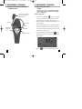
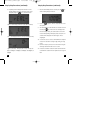
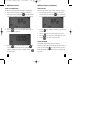
721 manual_082208.qxd
11/11/2008
7:09 AM
721
Combustible Gas Leak
Detector Instruction Manual
Page 1
721 manual_082208.qxd
11/11/2008
7:09 AM
Page 2
TABLE OF CONTENTS
A. INTRODUCTION
A. INTRODUCTION
1. Congratulations ..........................3
2. Product Description ....................3
1. Congratulations!!
B. SAFETY CONSIDERATIONS ..............4
C. TECHNICAL DATA
1. Features and Benefits..................5
2. Product Applications ..................5
3. Specifications..............................6
D. MEASUREMENT TECHNIQUES
1. Controls and Functions ..............7
2. Step by Step Procedures: ..........9
E. ADDITIONAL FEATURES..................12
F.
Thank you for purchasing TPI products. The 721 is easy
to use and is built to last. It is backed by a 3 year limited warranty. Please remember to complete and return
your product warranty registration card.
2. Product Description
The ergonomically designed 721 is a hand-held, combustible gas leak detector. It is capable of finding combustible gas leaks in pipes, fittings, regulators, etc.
Additional features include the capability to display
%LEL, leak level in ppm, and user adjustable alarm
point.
The 721 comes complete with the following accessories:
Carrying Pouch (A780)
Instruction Manual
Battery & Sensor (Installed & Calibrated)
TROUBLE SHOOTING GUIDE ..........15
H. MAINTENANCE ................................15
I.
2
ACCESSORIES ................................15
3
721 manual_082208.qxd
11/11/2008
7:09 AM
B. SAFETY CONSIDERATIONS
WARNING: Please follow manufacturers test
procedures whenever possible. Do not place the
sensor cage located on the end of the gooseneck on
hot or in hot locations.
GENERAL GUIDELINES
ALWAYS
•
•
Turn your detector on in a “clean air” environment away
from the test location.
Inspect the sensor cage to ensure it is securely attached.
NEVER
•
Place the detector or sensor cage in or on a hot item.
Page 4
C. TECHNICAL DATA
1. Features and Benefits
Auto Zero
Automatically sets the sensor to
zero at start up.
%LEL
Displays the percentage lower explosive
limit (LEL)
PPM
Displays the amount of leakage in
parts per million (ppm)
Mute
Mutes the speaker and earphone alarm
Zero
Manually sets the sensor to zero
Adjustable
Alarm
Alarm point can be set as required
Visual
Alarm
Alarm LED’s located on the front and
in the sensor cage tip
Auto Off
When enabled, the 721 turns off after
approximately 20 minutes to saves battery
life. Can be disabled.
2. Product Applications
Perform the following tests and/or measurements with the 721
leak detector:
• Locate combustible gas leaks in joints and fittings.
• Determine Lower Explosive Limit percentage.
• Determine the combustible gas leak level in ppm (parts per
million).
4
5
721 manual_082208.qxd
11/11/2008
7:09 AM
Page 6
3. Specifications
D. MEASUREMENT TECHNIQUES
Leak Detection Sensitivity (methane): 10ppm
1. Controls and Functions:
Gases Detected (partial listing): Acetone, Acetylene, Alcohol,
Ammonia, Benzene, Butane, Ethanol, Ethylene Oxide, Gasoline,
Hexane, Hydrogen, Methane, Naphtha, Natural Gas, Paint Thinners,
Propane, Solvents
Push Buttons
Short Press: Turns the 721 on.
Long Press (3 seconds): Turns
the 721 off.
Display Type: Dual display with backlight
Display Modes: Real (ppm), Leak Level (stepped ppm), %LEL
Ranges:
Short Press: Silences the alarm.
Long Press (3 seconds): Activates
Menu Mode.
Real ppm: 0 to 9999ppm
Stepped ppm: 0, 500, 1000, 3000, 5000, 9999ppm
%LEL: 0 to 19.9%
Short Press: Activates sensor
zero.
Long Press (3 seconds): Turns
the backlight on and off.
Audible Leak Indication: Adjustable tic rate via side thumb wheel
Alarm Indication: Visual and audible (User adjustable alarm level)
Sensor Test and Zero: Automatic at start up
Goose Neck: 16” long with visual alarm indicator in sensor housing
Operating Temperature: 32 to 122 (0 to 50)
Thumb
Controls speed of tick rate
Wheel
Gooseneck Length: 16 inches
Battery Type: “C” size Alkaline (2)
Size: 9.4” x 2.9” x 2.2” (240mm x 74mm x 55mm)
Weight: 1 lb (454g)
6
7
721 manual_082208.qxd
11/11/2008
7:09 AM
Page 8
D. MEASUREMENT TECHNIQUES
D. MEASUREMENT TECHNIQUES
1. Controls and Functions (continued):
2. Step by Step Procedures:
Instrument Layout
WARNING!
Turn the 721 in a “clean air” environment away from the
test area. Failure to do so may cause the 721 to display
sensor error and turn off.
Sensor cage containing
the sensor and visual
alarm indicator
Measurement Procedure:
1.
Turn the 721 on by pressing the
key. The 721 will begin
a 30 second countdown and “wait” will display. During this
countdown the sensor is being self tested and set to zero.
Speaker
2.
After the countdown is complete the 721 will display “0” and a
3.
At this point the display mode can be selected. Once the dis-
tic rate will begin.
Gooseneck
Display
On Indicator
Earphone
Jack
Keypad
play mode is selected the 721 will turn on in the same mode
Alarm LED
each time unless changed. If the display mode does not need
to be changed, proceed to step 8.
Tick adjust wheel
4.
To change the display mode press and hold the
key for
approximately 3 seconds to enter menu mode. The following
will be displayed:
5. Press the
8
key to proceed to the display mode screen.
9
721 manual_082208.qxd
11/11/2008
7:09 AM
Step by Step Procedures (continued):
6. Depending on the last display mode selected one of the
following displays will be seen. The display modes can be
changed by using the
key to cycle between them.
Page 10
Step by Step Procedures (continued):
7.
Once the desired display mode is selected, press the
key
and the following display will be seen:
8.
“REAL” mode will display leak levels in ppm (parts per million)
Press the
key again to exit menu mode and return to nor-
mal operation.
9.
Turn the thumbwheel on the side and set a consistent tic rate. If
necessary the
key can be used to zero the display. Enter
the area and begin testing. As a leak is found the tic rate will
increase and depending on the display mode selected, the concentration will be displayed on the LCD in ppm, %LEL, or
“LEL %” will display leak levels in %LEL (Lower Explosive Limit)
stepped ppm.
10. To locate the source of a leak, use the thumbwheel to nullify the
increase in tic rate and move along the pipe, fitting, etc. being
tested.
11. Continue to nulify any increases in tic rate and move along the
item being tested until the leak source is located.
“0ppm ud (ud=under)” will display leaks in steps. The steps are
0ppm, ud 500ppm, ud 1000ppm, ud 3000ppm, ud 5000ppm, ud
9999ppm
10
12. If the leak concentration is above the alarm level the alarm will
sound and LED’s located in the front panel and sensor cage will
flash.
11
721 manual_082208.qxd
11/11/2008
7:09 AM
Page 12
E. Additional Features:
Additional Features (continued):
Alarm Level Adjustment
Auto Power Off
The alarm level can be adjusted by performing the following steps:
The auto power off feature can be enabled or disabled as required:
1.
1.
After the 721 has been turned on and has gone through the
warm up period, press and hold the
key for approximately
warm up period, press and hold the
3 seconds to enter menu mode. The following will be displayed:
2.
Press the
key to proceed to the display mode screen.
3.
Press the
key to proceed to the alarm adjustment screen.
After the 721 has been turned on and has gone through the
key for approximately
3 seconds to enter menu mode. The following will be displayed:
2.
The following will be displayed.
Press the
key to enable (ys) or disable (no) the auto power
off feature.
3.
Press the
key to proceed to the display mode screen.
4.
Press the
key to proceed to the alarm adjustment screen.
5.
Press the
key to return to normal operation.
Display Backlight
The backlight can be activated at any time as required:
4.
Press the
key to increase the alarm level or the
key
After the 721 has been turned on and has gone through the warm up
to decrease the alarm level. The alarm can be adjusted from
period, press and hold the
100ppm to 5000ppm in increments of 100ppm. Press the
activate the backlight. The backlight will remain on for approximately
key when finished.
20 seconds.
12
key for approximately 3 seconds to
13
721 manual_082208.qxd
11/11/2008
7:09 AM
Page 14
Additional Features (continued):
F. Trouble Shooting
Mute Function
Problem
Corrective Action
When the 721 encounters a gas concentration above the alarm set
SENS ERR in display
Replace sensor
point the alarm will begin to sound. Pressing the
Tick rate inconsistent
Replace batteries / sensor
silence the alarm.
Weak LCD display
Replace Batteries
Zero Function
G. Maintenance
key will
If the 721 fails to auto zero the zero key can be used to zero the display. Turn the 721 on in a clean air environment, wait for the sensor
test to end, then press the
Battery Replacement:
Depress the latch on the back housing and slide the cover down.
Replace batteries (2 x “C” alkaline) and reattach the cover.
key.
Sensor Replacement:
Battery Indicator
The battery indicator is located in the upper right corner of the display
Turn the 721 off. Turn the sensor cage counter clockwise and remove
it. Unplug the old sensor and discard. Replace sensor and sensor cap.
and monitors the condition of the battery:
Battery indicator
Cleaning your 721:
Use a mild detergent and slightly damp cloth to clean the surfaces of
the 721. For factory service please return your 721 to:
TPI / Attn: Service
9615 SW Allen Blvd. Suite 104
Beaverton, OR 97005
The battery indicator will show full capacity (
(
), one quarter capacity (
), half capacity
), and replace (
).
H. Accessories
Replacement Sensor: A739
Soft Pouch: A780
Earphone: A710
14
15
721 manual_082208.qxd
11/11/2008
7:09 AM
Test Products International, Inc.
9615 SW Allen Blvd., Ste. 104
Beaverton, OR 97005
Tel: 503-520-9197 Fax: 503-520-1225
www.tpi-thevalueleader.com
Test Products International, Ltd.
342 Bronte Road South, Unit #9
Milton Ontario Canada L9T5B7
Tel: 905-693-8558 Fax: 905-693-0888
Page 16