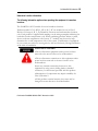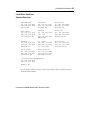
1
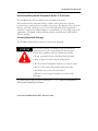
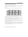
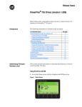
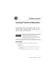
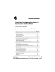
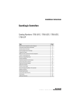
Installation Instructions
ControlLogix AutoMax DCSNet and AutoMax
Remote I/O Communication Interface Module
(Catalog Number 56AMXN/B)
Use this document as a guide to install the ControlLogix AutoMax DCS and
AutoMax Remote I/O communication interface module. The following table lists
what this manual contains and where to find specific information.
Topic
See Page
Important User Information
2
Understand Compliance to European Union Directive
4
Preventing Electrostatic Discharge
5
Identify Module Features
6
Set the Network Type and Drop Address Switches
7
Prepare the Chassis for Module Installation
8
Determine Module Slot Location
9
Install the Module
11
Wire the Module for the AutoMax Network
13
Apply Chassis Power
14
Interpreting the Alphanumeric Display
15
Interpreting the LED Status Indicators
17
Specifications
21
Support
22
Publication 56AMXN-IN002A-EN-P November 2002
2 DCSNet/RE RIO Module
Important User Information
Because of the variety of uses for the products described in this publication, those
responsible for the application and use of this control equipment must satisfy
themselves that all necessary steps have been taken to assure that each application
and use meets all performance and safety requirements, including any applicable
laws, regulations, codes and standards.
The illustrations, charts, sample programs and layout examples shown in this guide
are intended solely for purposes of example. Since there are many variables and
requirements associated with any particular installation, Rockwell Automation does
not assume responsibility or liability (to include intellectual property liability) for
actual use based upon the examples shown in this publication.
Allen-Bradley publication SGI-1.1, Safety Guidelines for the Application, Installation and
Maintenance of Solid-State Control (available from your local Rockwell Automation
office), describes some important differences between solid-state equipment and
electromechanical devices that should be taken into consideration when applying
products such as those described in this publication. Reproduction of the contents of
this copyrighted publication, in whole or part, without written permission of
Rockwell Automation, is prohibited.
Publication 56AMXN-IN002A-EN-P November 2002
DCSNet/RE RIO Module 3
Throughout this manual we use the following notes to make you aware of safety
considerations:
Identifies information about practices or circumstances
that have the potential to create an explosion hazard.
Identifies information about other practices or
circumstances that can lead to personal injury or death,
property damage or economic loss.
Warning and Attention statements help you to:
• identify a hazard
• avoid a hazard
• recognize the consequences
We use the following note to call attention to critical information:
Identifies information that is critical for successful
application and understanding of the product.
Publication 56AMXN-IN002A-EN-P November 2002
4 DCSNet/RE RIO Module
Understand Compliance to European Union Directive
If this product bears the CE marking, it is approved for installation within the
European Union and EEA regions. It has been designed and tested to meet the
following directives.
EMC Directive
This product is tested to meet Council Directive 89/336/EEC Electromagnetic
Compatibility (EMC) and the following standards, in whole or in part, documented
in a technical construction file:
• EN 50081-2 EMC - Generic Emission Standard, Part 2 - Industrial Environment
• EN 50082-2 EMC - Generic Immunity Standard, Part 2 - Industrial Environment
This product is intended for use in an industrial environment.
Low Voltage Directive
This product is tested to meet Council Directive 73/23/EEC Low Voltage, by
applying the safety requirements of EN 61131-2 Programmable Controllers, Part 2 Equipment Requirements and Tests.
For specific information required by EN 61131-2, see the appropriate sections in this
publication, as well as the following Allen-Bradley publications:
• Industrial Automation Wiring and Grounding Guidelines, publication 1770-4.1
• Automation Systems Catalog, publication B113
Open style devices must be provided with environmental and safety protection by
proper mounting in enclosures designed for specific application conditions. See
NEMA Standards publication 250 and IEC publication 529, as applicable, for
explanations of the degrees of protection provided by different types of enclosure.
Publication 56AMXN-IN002A-EN-P November 2002
DCSNet/RE RIO Module 5
Enclosure and Environmental Requirements Specific To This Product
The 56AMXN/B is NOT suitable for use in hazardous locations.
This product must be mounted within a suitable system enclosure to prevent
personal injury resulting from accessibility to live parts. The interior of this enclosure
must be accessible only by the use of a tool. This industrial control equipment is
intended to operate in a Pollution Degree 2 environment, in overvoltage category II
applications, (as defined in IEC publication 664A) at altitudes up to 2000 meters
without derating.
Preventing Electrostatic Discharge
The 56AMXN/B module is sensitive to electrostatic discharge.
Electrostatic discharge can damage integrated circuits or
semiconductors if you touch backplane connector pins.
Follow these guidelines when you handle the module:
• Touch a grounded object to discharge static potential
• Wear an approved wrist-strap grounding device
• Do not touch the backplane connector or connector pins
• Do not touch circuit components inside the module
• If available, use a static-safe work station
• When not in use, keep the module in its static-shield
packaging
For additional information refer to publication 1770-4.1, Industrial Automation
Wiring and Grounding Guidelines.
Publication 56AMXN-IN002A-EN-P November 2002
6 DCSNet/RE RIO Module
ATTENTION
Identify Module Features
Refer to the following figure to identify the hardware components of the
56AMXN/B module.
DCSNet / RE RIO
XXXX
NET
CLX
OK
Network
The module has:
•
A label to indicate that it is a scanner for AutoMax
DCSNet and remote I/O
•
A 4-character scrolling display (XXXX)
•
3 LEDs, labelled NET, CLX, and OK, to indicate the
status of the network, the connection to the
ControlLogix processor, and its own internal state
•
a 9-pin D-shell connector to connect to the DCS or
remote I/O network
•
switches at the top of the module to set the mode of
operation and the drop number and drop depth
Publication 56AMXN-IN002A-EN-P November 2002
DCSNet/RE RIO Module 7
Set the Network Type and Node Address Switches
Before you install the module, you must set the network type, drop number and drop
depth using the switches at the top of the module.
The two switches at the left set the drop depth, the two at the right set the drop
number.
The following table shows how to set the switches for each mode of operation.
Depth 10
Depth 1
Drop 10
Drop 1
DCS
Master
0
0
0
0
DCS slave
Drop depth
10’s digit
Drop depth
1’s digit
Drop Number
10’s digit
Drop number
1’s digit
Remote
I/O Master
0
1
0
0
For example, to configure the 56AMXN/B as a DCS slave with drop number 17,
drop depth 5, set the switches to 0, 5, 1, and 7 from left to right.
Any other settings are invalid and result in the module going into “Thumbwheel
test” mode. In thumbwheel test mode, the display shows the current switch settings.
It doesn’t go out of thumbwheel test mode until you cycle power.
In thumbwheel test mode, the 56AMXN/B initially displays “Thumb Test Mode”
on the 4-character display, displays the switch settings for 5 seconds, then resumes
displaying “Thumb Test Mode”
For DCS slave operation, if the drop number and drop depth are individually valid
but the combination results in invalid drop numbers (for example, drop number 55,
drop depth 2), the module displays an error message on the 4-character display but
does not enter Thumbwheel test mode.
Publication 56AMXN-IN002A-EN-P November 2002
8 DCSNet/RE RIO Module
Prepare the Chassis for Module Installation
Before you install the 56AMXN/B module, you must install and connect a
ControlLogix chassis and power supply.
For information on installing these products, refer to the publications listed in the
following table.
Chassis Type
Chassis
Power
Power Supply
Installation
Supply
Installation
Series B: 1756-A4, -A7,
Pub. No.
1756-PA72/B
Pub. No.
-A10, -A13
1756-IN080
1756-PB72/B
1756-5.67
1756-PA75/A
Pub. No.
1756-PB75/A
1756-5.78
Publication 56AMXN-IN002A-EN-P November 2002
DCSNet/RE RIO Module 9
Determine Module Slot Location
The figure below shows chassis slot numbering in a 4-slot chassis. Slot 0 is the first
slot and is always the leftmost slot in the rack (the first slot to the right of the power
supply). You can use any size ControlLogix chassis and install the module in any slot.
You can also install multiple 56AMXN/B modules in the same chassis. You can
install as many modules as your power supply can accommodate (i.e., number for
which the power supply is rated).
Publication 56AMXN-IN002A-EN-P November 2002
10 DCSNet/RE RIO Module
Installing or Removing the Module While Power Is Applied
Versions of the 56AMXN hardware prior to O-57677-1 do NOT support removal
and insertion under power.
The hardware version can be identified by looking for a sticker with the part number
O-57677-1 or above on the module’s printed circuit (near the serial number – you do
not need to disassemble the 56AMXN to find the sticker). Modules with no stickers
are hardware version O-57677 and do NOT support removal and insertion under
power
For hardware versions O-57677-1 and above, you can install or remove the module
while chassis power is applied if you observe the following precautions.
When you insert or remove a module while backplane
power is on, an electrical arc may occur. An electrical arc
can cause personal injury or property damage by:
• sending an erroneous signal to your system’s actuators
causing unintended machine motion or loss of process
control.
• causing an explosion in a hazardous environment.
Repeated electrical arcing causes excessive wear to
contacts on both the module and its mating connector.
Worn contacts may create electrical resistance that can
affect module operation.
Publication 56AMXN-IN002A-EN-P November 2002
DCSNet/RE RIO Module 11
Install the Module
Do not force the module into the backplane
connector. If you cannot seat the module with
firm pressure, check the alignment. Forcing the
module into the chassis can damage the
backplane connector or the module.
Publication 56AMXN-IN002A-EN-P November 2002
12 DCSNet/RE RIO Module
Removing or Replacing the Module (When Applicable)
If you are replacing an existing module with an identical one, and you want to
resume identical system operation, you must install the new module in the same slot.
You must also set the switches to the same settings and run the configuration
program and download the appropriate configuration to the module.
Publication 56AMXN-IN002A-EN-P November 2002
DCSNet/RE RIO Module 13
Wire the Connector for the AutoMax Network
Use a drop cable, 612574-36R, available through Rockwell Automation Systems
Business, and passive tap M/N 57C380 to connect the module to the coaxial
network cable. This cable turns down and has a ferrite to reduce EMI. This cable
must be used in CE applications. You can also use drop cable 612403-036R but it
points up.
The drop cable is a 3-foot long multi-conductor cable with 9-pin D-shell connectors
at each end. Connect one end to the connector on the module and the other end to
the passive tap.
The passive tap has two BNC connectors for connection to the coaxial cables and
terminating loads.
The network coaxial cable must be terminated with 75 ohm terminating loads
attached to the taps at the physical ends of the network. There should be two and
only two terminators on the network.
For DCS, the network cable can be RG-59/U or RG-11/U. For remote I/O, the
cable must be RG-59/U.
Apply Chassis Power
Turn the rack power supply on.
Publication 56AMXN-IN002A-EN-P November 2002
14 DCSNet/RE RIO Module
Check Power Supply and Module Status
The rack power supply indicator should be green.
The module OK LED should be solid red, then solid green.
The alphanumeric display shows the following messages at powerup.
Alphanumeric Status Display Powerup Messages
B#nn
Stages in the startup processes
Boot
56AMXN Ver
1.xx.xx
Module firmware version
Troubleshooting the Power Supply
If the alphanumeric indicator on the 56AMXN/B module does not cycle through
these messages on powerup, refer to the following table and to the Troubleshooting
section that follows.
Power Supply Indicator
If the POWER
indicator is:
Off
Power Supply Status is
Recommended Action:
Not operating
Turn power switch ON.
Check power wiring
connections.
Check fuse.
On
Operating
Publication 56AMXN-IN002A-EN-P November 2002
None, normal operation.
DCSNet/RE RIO Module 15
Interpreting the Alphanumeric Display
The 56AMXN/B module displays alphanumeric messages that provide diagnostic
information about your module. The alphanumeric display displays warning
messages twice, then resumes the normal display. The following table summarizes
the messages.
Message
Description
56AMXN Ver x.xx.xx
The module’s firmware version, displayed at
powerup.
Error: Heard Another DCS
Master
The module is configured as a DCS master and has
heard another DCS master on the network.
DCS Master
The module is a DCS master. Displayed during
normal operation.
Drop xx OffLine
DCS drop xx has gone offline.
DCS Slave Invalid Depth 0
The drop number switches are set for a drop number
from 1 to 55 but the drop depth switches are set to 0.
DCS Slave Drop+Depth 'xx'
Too High
The combination of drop number and drop depth
results in invalid drop numbers (>55). Check the
switch settings.
DCS Slave Drop=xx
Depth=xx Waiting...
The module is configured as a DCS slave with the
drop number and depth displayed, but is not
currently being scanned by a DCS master.
Error: Heard Duplicate DCS
Slave Drop xx
The module is configured as a DCS slave and has
heard a drop on the network with a drop number that
overlaps one of its active drops.
DCS Slave Drop=xx
Depth=xx
The module is configured as a DCS slave, with the
drop number and drop depth shown. Displayed
during normal operation.
Drop xx Timeout
DCS drop xx has timed out.
Mon Drop xx Timeout
Monitored DCS drop xx has timed out.
Firmware Update...
The firmware on the module is being updated.
Publication 56AMXN-IN002A-EN-P November 2002
16 DCSNet/RE RIO Module
Message
Description
Error: Heard Another RIO
Master
The module is configured as a Remote I/O master
and has heard another Remote I/O master active on
the network.
RIO Master
The module is configured as a Remote I/O master.
Displayed during normal operation.
Drop x Config Mismatch
The configuration for remote I/O drop x in Flash
memory on the module doesn’t match the drop on
the network.
Drop x OffLine
Remote I/O drop x is offline.
RIO FLASH Config Invalid
The module is configured as a Remote I/O master
and the configuration in FLASH memory is invalid.
Run 56AmxnRioCfg and configure the module.
Flash config drop mismatch
Configuration in FLASH is incompatible with current
switch settings
Thumb Test Mode
The module is in thumbwheel test mode.
Publication 56AMXN-IN002A-EN-P November 2002
DCSNet/RE RIO Module 17
Interpreting the LED Status Indicators
The three LED status indicators on the module provide information about your
module and the status of each channel. The following tables outline the indicator
condition and the corresponding status, and explain what each condition means.
NET LED – DCS/RIO Network Status
The NET LED indicates the status of the network connection. It is green if the
network status is good. If it is red, the following table shows possible causes.
Operating
Mode
Meaning
DCS Slave
Red if no master is heard or Active
DCS Master
Red if no Drops are found or if a Drop goes offline (1
sec)
RIO Master
Red if not all drops in configuration are active, or if
extra drops are found or any other configuration
mismatch exists
CLX LED – ControlBus Status
The CLX LED indicates the status of communication with the ControlLogix
processor.
Color
Meaning
Red
The module has returned an error, received an error or
refused a connection from the backplane. Look at the debug
log in 56AmxnMon for further information.
Yellow
No errors, but no activity
Green
An active connection is open or Bridging is active or DCS
registers are being accessed
Publication 56AMXN-IN002A-EN-P November 2002
18 DCSNet/RE RIO Module
OK LED – Module Health
A bicolor OK LED indicates module health. A red LED indicates that module
startup diagnostics have failed or a major module fault such as watchdog bite or
jabber inhibit has occurred. Green indicates that the card has passed all power-up
diagnostics and is functioning normally. This LED is red during powerup.
If all three LEDs are solid red and the 4-character display shows something like
M#66, this indicates that a fatal error has occurred. Refer to the User Guide for
information on clearing fatal errors.
Where to Find Information on Configuring Your 56AMXN/B Module
Now that you have installed your AutoMax DCS/RIO module, you must configure
it. For this information, refer to the configuration chapters of your 56AMXN User’s
Guide, publication 56AMXN-UM002A-EN-P.
This manual is supplied on the 56AMXN/B distribution CD. The CD also contains
the Adobe PDF reader.
Publication 56AMXN-IN002A-EN-P November 2002
DCSNet/RE RIO Module 19
Hazardous Location information
The following information applies when operating this equipment in hazardous
locations:
The 56AMXN is NOT suitable for use in hazardous locations.
Products marked “CL I, DIV 2, GP A, B, C, D” are suitable for use in Class I
Division 2 Groups A, B, C, D, Hazardous Locations and nonhazardous locations
only. Each product is supplied with markings on the rating nameplate indicating the
hazardous location temperature code. When combining products within a system,
the most adverse temperature code (lowest “T” number) may be used to help
determine the overall temperature code of the system. Combinations of equipment
in your system are subject to investigation by the local Authority Having Jurisdiction
at the time of installation.
EXPLOSION HAZARD
• Do not disconnect equipment unless power has been
removed or the area is known to be nonhazardous.
• Do not disconnect connections to this equipment unless
power has been removed or the area is known to be
nonhazardous.
Secure any external connections that mate to this
equipment by using screws, sliding latches, threaded
connectors, or other means provided with this product.
• Substitution of components may impair suitability for
Class I, Division 2.
• If this product contains batteries, they must only be
changed in an area known to be nonhazardous.
Publication 56AMXN-IN002A-EN-P November 2002
20 DCSNet/RE RIO Module
Specifications
Parameter
Specification
Module Location
ControlLogix chassis
Maximum Backplane
Current Load
650mA @ +5.1V dc and 75mA @ 24 V dc from
I/O chassis backplane
Power dissipation
5W maximum
Environmental
Conditions:
Operational
Temperature
0-60°C (32-140°F)
Storage Temperature
–40 to 85°C (–40 to 185°F)
Relative Humidity
5-95% without condensation
Shock Unpackaged
30g operational
50g non-operational
Vibration Unpackaged
Agency Certification
(when product or
packaging is marked)
2g from 10-150Hz
Listed Industrial Control
Equipment
Marked for all applicable directives
User Manual
Publication 56AMXN-UM002A-EN-P
Publication 56AMXN-IN002A-EN-P November 2002
DCSNet/RE RIO Module 21
Local Drive Solutions
Contact Directory
New England
Ph. 508.357.8431
Fax 508.485.5059
Boston MA
Southeast
Ph. 770.277.0277
Fax 770.682.6491
Atlanta GA
Gulf Coast
Ph. 281.233.0300
Fax 281.233.0101
Houston TX
West Coast
Ph. 626.969.7647
Fax 626.334.8320
Los Angeles CA
Eastern
Ph. 732.225.1360
ext. 110
Fax 732.225.7833
Edison NJ
Carolinas
Ph. 704.525.1455
Fax 704.525.9025
Charlotte NC
Midwest
Ph. 630.860.1090
Fax 630.787.0309
Chicago IL
St.
Ph.
Fax
St.
Ohio Valley
Ph: 513.943.1145
Fax 513.943.7438
Cincinnati OH
Great Lakes
Ph. 440.604.8421
Fax 440.604.8437
Cleveland OH
North Central
Ph. 651.633.0540
Fax 651.633.7181
Minneapolis MN
Louis
314.770.0168
314.770.0268
Louis MO
Drive/Systems Headquarters
Ph: 262.512.8636
Fax 262.512.8573
Mequon, WI
If you need to make a return, contact the nearest office to obtain a return
authorization number.
Publication 56AMXN-IN002A-EN-P November 2002
22 DCSNet/RE RIO Module
Publication 56AMXN-IN002A-EN-P November 2002
DCSNet/RE RIO Module 23
Publication 56AMXN-IN002A-EN-P November 2002
24 DCSNet/RE RIO Module
www.rockwellautomation.com
Corporate Headquarters
Rockwell Automation, 777 East Wisconsin Avenue, Suite 1400, Milwaukee, WI, 53202-5302 USA, Tel: (1) 414.212.5200, Fax: (1)
414.212.5201
Headquarters for Allen-Bradley Products, Rockwell Software Products and Global Manufacturing Solutions
Americas: Rockwell Automation, 1201 South Second Street, Milwaukee, WI 53204-2496 USA, Tel: (1) 414.382.2000, Fax: (1)
414.382.4444
Europe: Rockwell Automation SA/NV, Vorstlaan/Boulevard du Souverain 36-BP 3A/B, 1170 Brussels, Belgium, Tel: (32) 2 663 0600,
Fax: (32) 2 663 0640
Asia Pacific: Rockwell Automation, 27/F Citicorp Centre, 18 Whitfield Road, Causeway Bay, Hong Kong, Tel: (852) 2887 4788, Fax:
(852) 2508 1846
Headquarters for Dodge and Reliance Electric Products
Americas: Rockwell Automation, 6040 Ponders Court, Greenville, SC 29615-4617 USA, Tel: (1) 864.297.4800, Fax: (1) 864.281.2433
Europe: Rockwell Automation, Brühlstraße 22, D-74834 Elztal-Dallau, Germany, Tel: (49) 6261 9410, Fax: (49) 6261 1774
Asia Pacific: Rockwell Automation, 55 Newton Road, #11-01/02 Revenue House, Singapore 307987, Tel: (65) 351 6723, Fax: (65) 355
1733
Publication 56AMXN-IN002A-EN-P – November, 2002
Copyright © 2001 Rockwell Automation. All rights reserved. Printed in Canada.
Publication 56AMXN-IN002A-EN-P November 2002