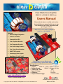
1
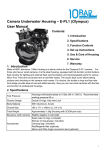
Product Title Class D Audio Power Amplifier 250W X 2 or 500W X 1 RMS Power Users Manual Please take the time to carefully read and understand this users manual and be sure to pay close attention to the safety instructions and operating procedures. Only 4 1/2” X 4 1/4 “ and 1 1/4” High! Small Size… BIG POWER! Features: Stereo or Bridged Configuration Power On / Off Switch Power and Error LED’s Click & Pop Noise Reduction Over Temperature Protection Over / Under Voltage Protection Over / Under Current Protection MOSFET DC Protection Housekeeping Power Supplies Small Size: 4.5” X 4.25” X 1.25” Class D Amps are very efficient and use half the energy of most other amps! Specifications: For more information, please visit us at: Output: 250W X 2 - 4 Ohm, 125W X 2 - 8 Ohm Bridged Output: 500W X 1 - Bridged - 8 Ohm THD+N, 1W - 1KHz: .02% Dynamic Range: 101 db Efficiency: Over 90% Required Power Supply: +/- 45 to +/-60V www.classDaudio.com email: [email protected] Incredible Sound… Affordable price! Copyright © 2009 class D audio - All Rights Reserved - www.classDaudio.com Made in the USA SAFETY PRECAUTIONS IMPORTANT SAFEGUARDS PLEASE READ CAREFULLY ALL THE FOLLOWING IMPORTANT SAFEGUARDS THAT ARE APPLICABLE TO YOUR EQUIPMENT AND YOUR SAFETY 1. Read the User’s Manual completely and refer to it frequently. 2. Retain the User’s Manual for future reference. 3. All warnings should be strictly adhered to. 4. This product should be operated using only the type of power source indicated in this manual. 5. Power supply cords and all connecting cables or wires should be routed so that they are not likely to be walked on or pinched. Pay particular attention to cords and cables at plugs, receptacles and terminal blocks. Always use wires with adequate ratings and safety certifications (CE, UL, etc.) 6. Your audio amplifier has been designed with your safety in mind. However, no design can Completely protect against incorrect use. Electrical circuits can be dangerous and/or lethal when a lack of caution or poor safety practice is used. Use caution in the presence of voltage above 24V as this poses a shock hazard. 7. Turn off the unit as soon as you stop actively using it. Unplug the power supply from the wall during a lightning storm or when the product is to be left unattended and unused for longer periods of time. 8. Do not use this product near water or in wet areas. Damp basements should be avoided. 9. Proper ventilation is crucial for safe and reliable operation. Never place anything on top of your amplifier that could obstruct airflow and cause the parts to overheat and damage the amplifier. Do not place your amplifier in a rack or bookcase unless proper ventilation is provided. 10. Care should be taken to prevent objects from falling and liquids from spilling into the unit. Do not subject the unit to excessive smoke, dust, vibration or shock. 11. During experimenting, make sure that all jumpers are properly seated in the correct position and that there are no foreign objects or solder bridges. 12. Always wear protective glasses and exercise caution when powering unit after any change is made. If possible, gradually rise input voltage and look for any abnormalities – smell or smoke, overheating, etc. 13. If you have any questions regarding safe and reliable operation of your amplifier, please email us at [email protected] 2 Dear Customer, The staff at Class D Audio would like to take this opportunity to congratulate and thank you for purchasing this high quality Class D Audio Amplifier. We are confident that your amplifier will be a pleasure to use and will provide you with many years of listening pleasure. Before using this amplifier, please take the time to carefully read and understand this users manual and pay close attention to the safety instructions and operating procedures. Becoming familiar with all the details about your amplifier will ensure safe usage and reliable operation. Take special care when working with high voltages and making adjustments. The effort you invest now will be well rewarded as time goes by. Please don’t hesitate to contact us at [email protected] with any questions you have. With best regards, The staff of classDaudio.com 3 WARNING This amplifier module is not intended for beginners. It requires familiarity with safe procedures for tests, measurements and usage of high voltage equipment. Exercise extreme caution when working with high voltages and always unplug the power before making any changes or adjustments. Electricity can cause severe injuries even with low voltages or currents. Therefore it is extremely important for you to read the following information before using your Class D Audio Amplifier. This amplifier module must only be used and operated by a competent person and in strict accordance with the instructions. We will not accept liability for any damage or injury caused by misuse, non compliance, or failure to follow safety procedures. 4 Please read this entire manual before making any connections to the amplifier. Be sure to read and adhere to all safety measures, precautions, and warnings. General The CDA2092X2NR is a high quality two-channel Class D audio power amplifier that features selectable half-bridge (stereo) and full-bridge (bridged) modes. The amplifier module is capable of driving an 8 Ohm or 4 Ohm load in stereo mode and 8 Ohm load in bridged mode. This amplifier uses high voltage, high speed driver ICs that feature a self-oscillating type PWM modulator for an extremely high performance design. This topology represents an analog version of a second-order sigma-delta modulation having a Class D switching stage inside the loop. The benefit of the sigma-delta modulation, in comparison to the carrier-signal based modulation, is that all the error in the audible frequency range is shifted to the inaudible upper-frequency range by nature of its operation. You will find when listening to this amplifier, a very clean somewhat warm sound along with a powerful and effortless bass response. Protection Circuitry The amplifier has built-in over current protection, over-voltage protection, undervoltage protection, speaker DC offset protection, and over temperature protection. In the event that any of these external fault conditions are detected, the amplifier circuitry will disable the output, turning on the yellow LEDs and turning off blue LEDs. If the fault condition persists, the protection circuit stays in shutdown until the fault is removed. Once the fault is cleared, the blue LEDs turn on and yellow LEDs turn off. If the error is only in one channel, then only that channel will be effected. Input On the input side of the board, you will notice 2 RCA input jacks for the left and right channels. These are analog inputs for the right and left channel signal source (preamp or ?). A proper input signal is an analog signal ranging from 20Hz to 20kHz with up to 3 VRMS amplitude with a source impedance of no more than 600 Ω. When using the amplifier in bridged mode, place the stereo/bridged jumper in bridged mode and use only the left input as clearly marked on the PCB. Output The left and right speaker terminal blocks are located on either side of the power supply input terminal block. The amplifier is designed for loads of 4 Ohm or 8 Ohm. Maximum output power depends on the value of the load and the power supply voltage. With a 4 Ohm load and a power supply voltage of +/-50 Volt, an output power of 250W RMS per channel can be achieved, an 8 Ohm load will be 125W RMS per channel, and in bridged mode, 500W RMS into an 8 Ohm load. Please note the PCB is clearly marked on the top and bottom side. When attaching speakers, please be sure to connect them to the proper polarity + and - or you will hear an out of phase and hollow sound coming from your speakers. When using the amplifier bridged mode, connect the speaker to the right and left channel + and + (positive) speaker outputs only. 5 Power supply A dual (bipolar) DC power supply of +/-45 to +/-60 Volt should be connected to the terminals V- GND V+ of the 3-position terminal block (shown in photo on following page). The minimum supply voltage is +/- 45V, and the maximum value is +/- 60V. Any value below or above the stated value, and the amplifier will not turn on due to the under voltage and over voltage protection that is built into this amplifier. The current capability of the power supply depends on the load and the voltage. The amplifier has a good power supply rejection ratio of -65 dB at 1kHz, and accepts any power supply topology as long as the supply voltages fit in the min and max range. Heat sink With it’s high efficiency, the amplifier can handle one-eighth of the continuous rated power without additional heatsink or forced air-cooling. One-eighth watt is generally considered to be a normal operating condition for safety standards. If the heatsink temperature rises above 100 °C, the over temperature protection shuts down both channels, turning on the yellow LEDs. Once the amplifier cools down, it will recover, the blue LEDs will turn back on, and the amplifier will resume normal operation. ON-OFF Switch You will see the small ON - OFF switch protruding from the lower right side of the power amplifier. In the OFF position, the power switch forces the amplifier to stay in shutdown (standby) mode. During the shutdown mode, the yellow LEDs are on, blue LEDs are off, and the output MOSFETs are kept off. When you put the switch in the ON position the yellow LED’s will turn off and the blue LEDS will turn on after about a 1 second delay. At this stage, when the blue LEDs are on, the amplifier is running and operating normally. We used a small switch because we recognize that most people will choose to mount the amp in an enclosure. Provisions for an external power switch are provided on the PCB and you will see how to utilize it in the following pages. Click & Pop Noise Reduction A Click and pop noise elimination function is built into the amplifier so it does not require any additional components for this function. Is most circumstances, you will not hear any pop or click noise when turning on or off the amplifier. Efficiency The amplifiers high efficiency of over 90% is achieved due to several factors such as: low conduction loss due to the dual FETs offering low RDS(ON), low switching loss due to the dual FETs offering low input capacitance for fast rise and fall times, and secure dead-time provided by the driver ICs avoiding cross-conduction. The PCB (printed circuit board) is clearly marked on the top and bottom side for safe and easy connections. 6 7 Precautions Power Switch DO NOT TOUCH! P2 and P3 are potentiometers that are used to adjust the switching frequency of the amplifier. They are factory pre-set and no further adjustment is required. The slightest move or adjustment will put the amplifier out of sync and possibly cause damage! The above photo shows potentiometers P2 and P3. Please do not touch or try to adjust these by yourself. The potentiometers are factory pre-set to 400KHz +/- 25KHz. At Higher frequencies, distortion due to switching time becomes significant. At lower frequencies the bandwidth suffers. The adjustment is very sensitive, and the slightest movement will put the amplifiers out of tolerance, so please do not touch them and make sure they do not get bumped or knocked out of position... This is not likely to happen, but still use care when handling the amplifier. If you choose to experiment with the adjustment of these potentiometers, you do so at your own risk and will you will void your warranty! The power switch is shown here only to show it’s location because it’s a little hard to see from the top view photos. You can also add an external power switch. Details are shown on page 9 of this manual. 8 Adding External LEDs & Power Switch Only attempt these modifications if you are experienced in electronics! Left Channel Blue LED Right Channel Blue LED Left Channel Yellow LED Right Channel Yellow LED External Power Switch This amplifier was designed with provisions for an external power switch, connectors, and LEDs for easy mounting in an enclosure. Only a SPST switch, two blue and two yellow LEDs, and some wire is needed. When using an external power switch, leave the onboard switch in the on position permanently. When installing external LEDs, be sure to note the + sign showing the pole position for the LEDs. The onboard terminal blocks and RCA jacks for inputs, power supply, and speaker outputs can be removed and soldered directly to the PCB board for a permanent instillation. These amplifiers can also be ordered from us without the RCA jacks and terminal blocks for easier and permanent installations. Existing LEDs can be 9 removed or left on the PCB. FINAL WORDS Once again, thank you for your purchase. We hope that this Class D Audio Power Amplifier will give you hours and hours of enjoyment as you experience the multitude of different qualities that Class D Audio presents. Also, please don’t forget to take extreme caution while working with high voltages. If you are not thoroughly familiar with the safety procedures, feel free to enlist the help of someone with experience in this field of work. There are many very knowledgeable people in online internet forums, and most are happy to help as they all share a passion for spreading the art and science of high quality sound reproduction. Thank you for Doing Your Part for the Environment ... Class D Amps are very efficient and use only about half the energy of most other amplifiers! 10 Warranty SUMMARY OF WARRANTY Class D Audio warrants to you, the ORIGINAL PURCHASER of each NEW Class D Audio product, for a period of one (1) year from the date of purchase by the original purchaser (the "warranty period") that the new Class D Audio product is free of defects in materials and workmanship. We further warrant the new Class D Audio product regardless of the reason for failure, except as excluded in this Warranty. ITEMS EXCLUDED FROM THIS CLASS D AUDIO WARRANTY This Class D Audio Warranty is in effect only for failure of a new Class D Audio product which occurred within the Warranty Period. It does not cover any product which has been damaged because of any intentional or unintentional misuse, accident, or negligence. It does not cover any loss or damage which is covered under any of your insurance contracts. This Class D Audio Warranty also does not extend to the new Class D Audio product if the serial number has been defaced, altered, or removed, or if the product has been modified or altered in any way. WHAT THE WARRANTOR WILL DO We will remedy any defect, regardless of the reason for failure (except as excluded), by repair or replacement. We will remedy the defect and ship the product from the service center or our factory within a reasonable time after receipt of the defective product at our authorized service center or our factory. All expenses in remedying the defect, including surface shipping costs in the United States, will be borne by us. (You must bear the expense of shipping the product between any foreign country and the port of entry in the United States including the return shipment, and all taxes, duties, and other customs fees for such foreign shipments). DISCLAIMER OF CONSEQUENTIAL AND INCIDENTAL DAMAGES YOU ARE NOT ENTITLED TO RECOVER FROM US ANY INCIDENTAL DAMAGES RESULTING FROM ANY DEFECT IN THE NEW CLASS D AUDIO PRODUCT. THIS INCLUDES ANY DAMAGE TO ANOTHER PRODUCT OR PRODUCTS RESULTING FROM SUCH A DEFECT. HOW TO OBTAIN WARRANTY SERVICE You must contact us at [email protected] for warranty service within the warranty period. All components must be shipped in the original box. Corrective action will be taken within a reasonable time of the date of receipt of the defective product by our authorized service center. If the repairs made by our authorized service center are not satisfactory, notify our authorized service center immediately. Copyright © 2009 class D audio - All Rights Reserved - www.classDaudio.com 11 Copyright © 2009 class D audio - All Rights Reserved - www.classDaudio.com 12