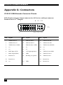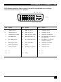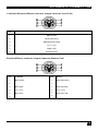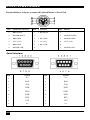
1
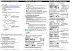
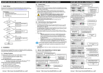
DVXI/XV-XM /XS KVM-EXTENDER
Welcome to the DVXi/XV KVM-Extender Family!
Thank you for purchasing an DVXi/XV KVM-Extender! We appreciate your business, and
we think you’ll appreciate the many ways that our DVXi/XV KVM-Extender will save you
money, time, and effort.
That’s because our DVXi/XV KVM-Extender is all about breaking away from the traditional
model of attaching a new display to DVI graphic source. Using the DVXi/XV KVMExtender, you can remotely locate monitor, keyboard and mouse up to 2.000m away from
your CPU.
Wherever long distances are usual, e.g. airports, industrial plants, call- centres or in
distributed computer centres, the DVXi/XV KVM-Extender is the best way, to solve all
problems in remotely locating your console. 8 different types are available: Singlehead and
Dualhead devices for PS2 keyboard/mouse and Singlehead and Dualhead devices for USB
keyboard/mouse. An Audio/serial Option is also available.
Using 3.2GBit transceivers, the full 60Hz framerate is available for resolution up to
1920x1200@60Hz and at least 30Hz for all lower resolutions. The devices are either adapted
for the Multimode (DVXI-xM) or Singlemode (DVXI-xS) data transfer.
This manual will tell you all about your new DVXi/XV KVM-Extender, including how to
install, operate, and troubleshoot it. For an introduction to the Converter, see Chapter 2. The
Converter product codes covered in this manual are:
For Multimode-Fibre 50/125µ or 62.5/125µ:
K464-1W:
K464-2W:
K464-1U:
K464-2U:
K464-SA:
K464-DA:
K464-SU:
K464-DU:
DVXi/XV-PM KVM-Extender for 1x DVI, PS2-Keyboard/Mouse
DVXi/XV-PM2 KVM-Extender for 1x DVI, PS2-Keyboard/Mouse
DVXi/XV-UM KVM-Extender for 1x DVI, PS2-Keyboard/Mouse
DVXi/XV-UM2 KVM-Extender for 1x DVI, PS2-Keyboard/Mouse
DVXi/XV-PMA KVM-Extender for 1x DVI, PS2-Keyboard/Mouse + serial/audio
DVXi/XV-PMA2 KVM-Extender for 2x DVI, PS2-Keyboard/Mouse + serial/audio
DVXi/XV-UMA KVM-Extender for 1x DVI, USB-Keyboard/Mouse + serial/audio
DVXi/XV-UMA2 KVM-Extender for 2x DVI, USB-Keyboard/Mouse + serial/audio
For Singlemode-Fibre 9/125µ:
K465-1W:
K465-2W:
K465-1U:
K465-2U:
K465-SA:
K465-DA:
K465-SU:
K465-DU:
DVXi/XV-PS KVM-Extender for 1x DVI, PS2-Keyboard/Mouse
DVXi/XV-PS2 KVM-Extender for 2x DVI, PS2-Keyboard/Mouse
DVXi/XV-US KVM-Extender for 1x DVI, USB-Keyboard/Mouse
DVXi/XV-US2 KVM-Extender for 2x DVI, USB-Keyboard/Mouse
DVXi/XV-PSA KVM-Extender for 2x DVI, USB-Keyboard/Mouse + serial/audio
DVXi/XV-PSA2 KVM-Extender for 2x DVI, USB-Keyboard/Mouse + serial/audio
DVXi/XV-USA KVM-Extender for 2x DVI, USB-Keyboard/Mouse + serial/audio
DVXi/XV-USA2 KVM-Extender for 2x DVI, USB-Keyboard/Mouse + serial/audio
1
DVXI/XV KVM-EXTENDER
Copyrights and Trademarks
©2007. All rights reserved. This information may not be reproduced in any manner without
the prior written consent of the manufacturer.
Information in this document is subject to change without notice and the manufacturer shall
not be liable for any direct, indirect, special, incidental or consequential damages in
connection with the use of this material.
All trademark and trade names mentioned in this document are acknowledged to be the
property of their respective owners.
Disclaimer
While every precaution has been taken in the preparation of this manual, the manufacturer
assumes no responsibility for errors or omissions. Neither does the manufacturer assume any
liability for damages resulting from the use of the information contained herein. The
manufacturer reserves the right to change the specifications, functions, or circuitry of the
product without notice.
The manufacturer cannot accept liability for damage due to misuse of the product or due to
any other circumstances outside the manufacturer’s control (whether environmental or
installation related). The manufacturer shall not be responsible for any loss, damage, or injury
arising directly, indirectly, or consequently from the use of this product.
Cautions and Notes
The following symbols are used in this guide:
CAUTION. This indicates an important operating instruction
that should be followed to avoid any potential damage to
hardware or property, loss of data, or personal injury.
NOTE. This indicates important information to help you make the best use of
this product.
2
EMPTY PAGE
.
3
DVXI/XV KVM-EXTENDER
EUROPEAN UNION DECLARATION OF CONFORMITY
This is to certify that, when installed and used according to the instructions in this
manual, together with the specified cables and the maximum cable length <3m, the
Units:
K464-1W, K464-2W, K464-1U, K464-2U
K464-SA, K464-DA, K464-SU, K464-DU
K465-1W, K465-2W, K465-1U, K465-2U
K465-SA, K465-DA, K465-SU, K465-DU
are shielded against the generation of radio interferences in accordance with the
application of Council Directive 89/336/EEC as well as these standards:
EN 55022:
EN 55024:
IEC 61000-4-2:
IEC 61000-4-3:
IEC 61000-4-4:
EN 61000-3-2
EN 61000-3-3
1999
1999
2001
2001
2001
2001
2002
Class A
The device was tested in a typical configuration with PC.
Oberteuringen, Thursday, March 15th, 2007
The management
This equipment has been found to comply with the limits for a Class A digital device,
pursuant to Part 15 of the FCC Rules. These limits are designed to provide reasonable
protection against harmful interference when the equipment is operated in a commercial
environment. This equipment generates, uses, and can radiate radio frequency energy and, if
not installed and used in accordance with the instruction manual, may cause harmful
interference to radio communications. Operation of this equipment in a residential area is
likely to cause harmful interference in which case the user will be required to correct the
interference at his own expense.
4
SAFETY-PRECAUTIONS AND
INSTALLATION GUIDLINES
Safety Precautions and Installation Guidelines
To ensure reliable and safe long-term operation, please note the following installation
guidelines:
•
Only use in dry, indoor environments.
•
The Remote unit, Local unit and any power supplies can get warm. Do not locate them
in an enclosed space without any airflow.
•
Do not place a power supply directly on top of a unit.
•
Do not obstruct a unit’s ventilation existing holes.
To safeguard against personal injury and avoid possible
damage to equipment or property, please observe the
following:
•
Only use power supplies originally supplied with the
product or manufacturer-approved replacements. Do not
attempt to dismantle or repair any power supply. Do not
use a power supply if it appears to be defective or has a
damaged case.
•
Connect all power supplies to grounded outlets. In each
case, ensure that the ground connection is maintained
from the outlet socket through to the power supply’s AC
power input.
•
Do not attempt to modify or repair this product.
5
DVXI/XV KVM-EXTENDER
Contents
1. Quick Setup
7
2. Overview
8
2.1
2.2
2.3
2.4
2.5
2.6
2.7
Introduction
Glossary
Example of a System
Features
Product Range
Compatibility
How to Use This Guide
3. Installation
3.1
3.2
3.3
3.4
Package Contents
Interconnection Cable Requirements
System Setup
Diagnostic LEDs
4. Service Setup
4.1
4.2
Setup at the Local Unit
Setup at the Remote Unit
8
8
9
10
11
12
13
14
14
15
16
26
27
28
31
5. Troubleshooting
32
Appendix A: Example Applications
34
Appendix B: Rack Mount Options
36
Appendix C: Devices with serial/AUDIO Option
40
Appendix D: Calling Technical Support
42
Appendix E: List of supported USB devices
43
Appendix F: Specifications
44
Appendix G: Connectors
46
6
QUICK SETUP
1. Quick Setup
This section briefly describes how to install your KVM extender system. Unless you are an
experienced user, we recommend that you follow the full procedures described in the rest of
this manual.
Install system
1.
2.
3.
4.
Connect Remote unit to KVM.
Connect Local unit to CPU or switch.
Connect Local and Remote units with matching interconnection cable
(fiber cables).
Power up the system.
NO
Power LED
illuminated?
YES
Link LED
illuminated?
Check p.s.u.’s and connection
to power outlet
NO
Check the fiber cable, and
fiber connectors
YES
Video OK
LED
illuminated?
NO
Check settings of graphic card
or boot CPU
YES
Done
7
DVXI/XV KVM-EXTENDER
2.
Overview
2.1
Introduction
A fibre KVM Extender is mainly used, to extend the maximum distance between a CPU and
his Keyboard / Monitor / Mouse considerably. In addition they are irrecoverable in
installations in electromagnetic hazardous environments (EMI). Normal Keyboard-/ Monitor/ Mouse extender cables (and Extender using traditional cables) cannot go so far and EMI
interferences may reduce the maximum distance and/or reliability. Using a DVXi/XV
Extender system, these limitations are past. Remain your CPU in a secure rack cabinet or data
center while accessing from a 2.000m remotely located place.
A basic KVM extension system comprises a Local unit (transmitter) and a Remote unit
(receiver). The Local unit connects directly to the computer (or a KVM switch system) using
the supplied cable(s). The user console (keyboard, mouse and monitor) attaches to the
Remote unit. The Remote and Local units communicate video and data information along the
interconnecting cable. Local units offer dual access, allowing the connection of a second user
console close to the computer.
2.2
Glossary
The following terms are used in this guide:
fibre
Singlemode or Multimode fibre cable
Singlemode
9µ Singlemode-fibre cable
Mulitmode
62,5µ Multimode- oder
50µ Multimode-fibre cable
KVM
Keyboard, Video and Mouse.
Console
Keyboard, Mouse and Monitor
Dual Access
A system allowing connection of Local and Remote user consoles.
Singlehead
An extender system that supports one monitor + Keyboard/Mouse
Dualhead
An extender system that supports two monitors + Keyboard/Mouse
DVI
Digital Video standard, installed by Digital Display Working Group
(www.ddwg.org) R, G, B, CLOCK in a data stream with up to
3x 1,6 Gbit/sec. Signals are TMDS Level.
PSU
The desktop power supply connected to the Local/Remote unit.
HID
Human Interface Devices are units, which are used for human access
to the CPU. They are a USB-device class of its own (e.g. Memory
Devices etc.). Besides of keyboard and mouse also touchscreen, light
pen, fingerprint sensor, graphic tablets etc. are HID devices.
8
OVERVIEW
2.3
Example of a System
CPU with DVI-D
Graphic card
Local Console
Optional
2. Monitor
DVXi/XV KVMExtender system
Optional
2. Monitor
Remote Console
DVXi/XV – KVM Extender system (example)
9
DVXI/XV KVM-EXTENDER
2.4
Features
All members of the DVXi/XV - DVI KVM Extender Series offer the following features:
•
Support for DVI-D Graphic cards (all devices)
•
Support for PS2-Keyboard and PS2-Mouse (K464-1W, K464-2W, K465-1W and K4652W)
•
Support for USB-Keyboard and USB-Mouse (K464-1U, K464-2U, K465-1U and K4652U)
•
Support for two monitors per system (K464-2W, K464-DA,K464-2U, K464-DU, K4652W, K465-DA, K465-2U und K465-DU)
Devices with USB- connectors support ONLY Keyboard and Mouse. It’s
possible, that other HID devices (Human Interface Device) like touchscreens, graphics tablets, barcode readers or similar are supported – but
there is no guarantee for this! The DVI-D Cat X KVM-Extender is NOT
suitable for use with other USB devices like Scanner, WEB- Cams, data
sticks etc.
The device never supports more than two devices – Keyboard and Mouse
or Keyboard and Touchscreen, etc. but not e.g. Keyboard, Mouse and
Touchscreen simultaneously. A Hub is allowed but does not raise the
number of supported devices
•
Maximum resolution: DVI-D: 1920x1200@60Hz over all allowed distances
all lower resolutions with refresh rates of at least 75Hz
•
Supporting 18 Bit (= 256K colours) or 24 Bit (=16M colours) colour depth
•
Using 3.2GBit transceivers, the full 60Hz frame rate is available for resolutions up to
1600x1200 @ 60Hz and at least 30Hz for all lower resolutions
•
Optional support of a transparent, serial interface with up to 19.2KBaud and hardware
handshake.
•
Optional support of a bidirectional audio interface.
•
Status indicator LEDs on each device.
•
Small footprint chassis.
•
Rack mount options available.
•
CPU cables + Adapters included.
10
OVERVIEW
2.5
Product Range
There are 16 products in the range and various upgrade kits:
DVXi/ET – Extender (fibre)
K462-1W (Multimode)
K462-SA (Multimode)
K462-2W (Multimode)
K462-DA (Multimode)
K462-1U (Multimode)
K462-SU (Multimode)
K462-2U (Multimode)
K462-DU (Multimode)
K463-1W (Singlemode)
K463-SA (Singlemode)
K463-2W (Singlemode)
K463-DA (Singlemode)
K463-1U (Singlemode)
K463-SU (Singlemode)
K463-2U (Singlemode)
K463-DU (Singlemode)
DVXi/ET-PM KVM-Extender for 1x DVI, PS2Keyboard, PS2-Mouse (Single Head)
DVXi/ET-PMA KVM-Extender for 1x DVI, PS2Keyboard, PS2-Mouse (Single Head) + serial/Audio
DVXi/ET-PM2 KVM-Extender for 2x DVI, PS2Keyboard, PS2-Mouse (Dual Head)
DVXi/ET-PMA2 KVM-Extender for 2x DVI, PS2Keyboard, PS2-Mouse (Dual Head) + serial/Audio
DVXi/ET-UM KVM-Extender for 1x DVI, USBKeyboard, USB-Mouse (Single Head)
DVXi/ET-UMA KVM-Extender for 1x DVI, USBKeyboard, USB-Mouse (Single Head) + serial/Audio
DVXi/ET-UMA2 KVM-Extender for 2x DVI, USBKeyboard, USB-Mouse (Dual Head)
DVXi/ET-UMA2 KVM-Extender for 2x DVI, USBKeyboard, USB-Mouse (Dual Head) + serial/Audio
DVXi/ET-PS KVM-Extender for 1x DVI, PS2Keyboard, PS2-Mouse (Single Head)
DVXi/ET-PSA KVM-Extender for 1x DVI, PS2Keyboard, PS2-Mouse (Single Head) + serial/Audio
DVXi/ET-PS2 KVM-Extender for 2x DVI, PS2Keyboard, PS2-Mouse (Dual Head)
DVXi/ET-PSA2 KVM-Extender for 2x DVI, PS2Keyboard, PS2-Mouse (Dual Head) + serial/Audio
DVXi/ET-US KVM-Extender for 1x DVI, USBKeyboard, USB-Mouse (Single Head)
DVXi/ET-USA KVM-Extender for 1x DVI, USBKeyboard, USB-Mouse (Single Head) + serial/Audio
DVXi/ET-US2 KVM-Extender for 2x DVI, USBKeyboard, USB-Mouse (Dual Head)
DVXi/ET-USA2 KVM-Extender for 2x DVI, USBKeyboard, USB-Mouse (Dual Head) + serial/Audio
Upgrade Kits
455-4G
19” Rackmount- Kit to mount up to 4 Singlehead devices
455-8G
19” Rackmount- Kit to mount up to 4 Dualhead devices
455-PS
19“ mountable power supply for up to three DVXI
devices.
455-1K
Mounting plate to mount by screws
455-2K
Mounting plate to mount by snap on
11
DVXI/XV KVM-EXTENDER
2.6
Compatibility
Interface Compatibility
•
Digital Video (DVI-D): Digital Video standard, installed by Digital Display Working
Group (www.ddwg.org) R, G, B, CLOCK in a data stream with up to
3x1,6 Gbit/sec. Signals are TMDS Level.
•
PS/2 Keyboard: Compatible with all standard keyboards. Certain keyboards with
enhanced features may also be supported with custom firmware.
•
PS/2 Mouse: Compatible with all standard 2-button, 3-button and wheel mice.
•
USB Keyboard: Compatible with all standard keyboards. Certain keyboards with
enhanced features may also be supported with custom firmware. Keyboards with built-in
hub are also supported – but there are never more than two HDI devices supported.
•
USB Mouse: Compatible with all standard 2-button, 3-button and wheel mice.
Devices with USB- connectors support ONLY Keyboard and Mouse. It’s
possible, that other HID devices (Human Interface Device) like touchscreens, graphics tablets, barcode readers or similar are supported – but
there is no guarantee for this! The DVI-D Cat X KVM-Extender is NOT
suitable for use with other USB devices like Scanner, WEB- Cams, data
sticks etc.
The device never supports more than two devices – Keyboard and Mouse
or Keyboard and Touchscreen, etc. but not e.g. Keyboard, Mouse and
Touchscreen simultaneously. A Hub is allowed but does not raise the
number of supported devices.
12
OVERVIEW
2.7 How to Use This Guide
This guide describes the installation and configuration of the DVXi/XV – Extender Series.
Although the connection and operation of the system is relatively straightforward, you should
consider the following before getting started:
Connection & Compatibility
If you have purchased an Extender Kit, this will contain all the cables required to connect the
Local unit to your PC or KVM switch. Please see also: Package Contents (page 14)
For information about connection and installation, see Installation, page 14.
DDC Information
Normally it is not necessary to make any adjustments to the DVXi- Extender. However, in
some circumstances, it may be necessary to redefine the source of DDC Information for the
CPU. By default, the DVXi/LC KVM-Extender uses its own internal DDC table. If this
setting does not satisfy your requirements, the DDC table can either be switched to the locally
attached screen or could be downloaded from remotely located screen and stored in the
internal DDC table.
To modify the DDC-Setup, see Service Setup (page 27).
Selecting the moment of switching to the next frame
The transmission of screen data in not synchronous to the screen change of the graphic card.
Normally, the transmission is terminated during displaying a frame on the screen. If the
device switches to the new frame during the displaying period of the old frame (somewhere
on the screen), it’s possible, that you can see horizontal screen breaks in the moment of
switching (default). On the other hand the device must idle, until the actual frame is displayed
completely (until VSYNC) -> the number of frames per second transmitted sinks.
To modify the switching behaviour, see Service Setup (page 27).
Compatibility
Devices with PS2 connectors are NOT compatible to devices with USB connectors.
13
DVXI/XV KVM-EXTENDER
3. Installation
For first-time users, we recommend that you carry out a test placement, confined to a single
room, before commencing full installation. This will allow you to identify and solve any
cabling problems, and experiment with the KVM extender system more conveniently.
3.1 Package Contents
You should receive the following items in your extender package (all types):
•
DVXi/XV KVM-Extender- pair (Local Unit + Remote Unit)
•
2x 5V DC universal power supply for the DVXi/XV - Extender
•
2x German type power cord
•
User manual (Quick Setup)
K464-1W, K464-2W, K465-1W and K465-2W (additionally):
•
KVM CPU cable set (1.8m) with one side: PS/2 (6-pin mini-DIN male) keyboard and
mouse connector and DVI-I video (DVI-I dual link male) connector – other side: DVI-I
video (DVI-I dual link male) connector
•
PS2-Keyboard-/ Mouse adapter to connect K/M to the Local Unit (keyboard can be
plugged in directly, without using an adapter)
K464-1U, K464-2U, K465-1U and K465-2U (additionally):
•
DVI-I (1,8m) video cable (DVI-I dual link male-to-male)
•
USB (1,8m) cable (USB type A to type B)
K464-2W, K464-2U, K465-2W and K465-2U (additionally):
DVI-I (1,8m) video cable (DVI-I dual link male-to-male)
•
K464-SA, K464-SU, K465-SA and K465-SU (additionally):
•
Serial cable 1,8m (Serial DB9-male/female)
•
2 Audio Anschlusskabel 1,8m
K464-DA, K464-DU, K465-SA and K465-DA (additionally):
•
DVI/serial/audio cable set 1,8m
If anything is missing, please contact Technical Support (see Appendix F – Calling
Technical Support).
14
INSTALLATION
3.2 Interconnection Cable Requirements
To connect the Local and Remote units you will need:
•
DVI, PS2-Keyboard, PS2-Mouse: Connect the supplied KVM CPU cable set to your
CPU (KVM.- Switch, etc.). Please ensure that the connection is tension-free! Devices
K464-1W, K464-2W, K465-1W + K465-2W
•
DVI, USB-Keyboard, USB-Mouse: Connect the supplied KVM CPU cable set to your
CPU (KVM.- Switch, etc.). Please ensure that the connection is tension-free! Devices
K464-1U, K464-2U, K465-1U + K465-2U
•
DVI: Connect the supplied DVI CPU cable set to your CPU (KVM.- Switch, etc.).
Please ensure that the connection is tension-free! Devices K464-2W, K464-2U, K4652W und K465-2U
•
DVI/serial/audio: Connect the supplied DVI/serial/audio cable set to your CPU (DVI-I
to DVI-I, serial DB9-male/female and audio).
•
Serial: Connect the supplied serial cable to your CPU.
•
Audio: Connect the supplied audio cable to your CPU.
•
Fibre Cables:
•
Multimode: Two fibres 50µm or 62.5µm. E.g. I-V(ZN)H 2G50 (In house
patch cable)or I-V(ZN)HH 2G62,5 (In house Breakout cable) or I/AD(ZN)H
4G50 (in house OR outdoor Breakout cable, stress resistant) or
A/DQ(ZN)B2Y 4G62,5 (outdoor cable, stress resistant with protection against
animal biting) All notations acc. VDE specification.
•
Singlemode: Two fibres 9µm. E.g. I-V (ZN)H 2E9 (In house patch cable) or IV(ZN)HH 2E9 (In house Breakout cable) or I/AD(ZN)H 4E9 (in house OR
outdoor Breakout cable, stress resistant) or A/DQ(ZN)B2Y 4G9 (outdoor
cable, stress resistant with protection against animal biting) All notations acc.
VDE specification.
A point to point connection is required. Having one or more patch panels
in the line is possible and allowed. Not allowed is a connection from the
fibre link interface to any other products, especially telecommunications or
network equipment.
•
Power Supply
Connect the supplied 5V/DC power supplies to the Plug terminal on the rear of both
Local and Remote units.
15
DVXI/XV KVM-EXTENDER
3.3 System Setup
To install your DVXi/XV – Extender system:
1.
Switch off all devices.
2.
Connect your keyboard, monitor(s) and mouse to the Remote unit (depending on device
type). Please ensure, to not swap Mouse- and Keyboard connector. The (PS2-) Keyboard
connector is purple and the (PS2-) Mouse connector is green.
3.
Using the supplied CPU KVM cable(s), connect the keyboard, monitor(s) and mouse
connectors on the computer (or KVM switch). Please ensure, to not swap Mouse- and
Keyboard connector. The Keyboard connector is purple and the Mouse connector is
green.
4.
Connect the interconnect cable (fibre cable) to the local and the remote unit.
5.
Connect the 5V power supply to power the unit.
Only use the power supply originally supplied with this
equipment or a manufacturer-approved replacement.
6.
For a dual access system, connect the monitor for the Local console to the appropriate
port on the Local unit. The port may also be used to feed into a KVM switch.
To the local (PS2-) Keyboard-/ Mouse port you can attach a Keyboard directly or
Mouse/ Keyboard together, using the delivered adapter.
To attach a local (USB-) Keyboard/Mouse, please use additional USB port(s) at your
CPU or use a USB Hub inbetween CPU and local unit’s USB connector.
7.
16
Power up the system.
INSTALLATION
Connect to CPU:
DVI, keyboard, mouse
Local DVI-Monitor
port Connect to Local
console monitor
Local keyboard/ mouse port
Solely Keyboard may be
plugged in directly,
keyboard/mouse through
equipped adapter
DVXi/XV KVM-Extender K464-1W and K465-1W Local Unit
Remote DVI-Monitor
port– connect to
Remote console
monitor
Remote keyboard
port
Remote mouse port
DVXi/XV KVM-Extender Type K464-1W and K465-1W Remote Unit
Connect to CPU:
DVI graphic card
Local DVI-Monitor
port Connect to Local
console monitor
Connect to CPU:
USB
DVXi/XV KVM-Extender Type K464-1U and K465-1U Local Unit
17
DVXI/XV KVM-EXTENDER
Remote DVI-Monitor port– connect
to Remote console monitor
Remote keyboard/mouse
port
DVXi/XV KVM-Extender Type K464-1U and K465-1U Remote Unit
INTERCONNECT – carries video and
data signals – connect to Local/
remote unit with fiber cable
Connect to 5V Power
supply
DVXi/XV KVM-Extender Type K464-1W, K464-1U, K465-1W, K465-1U
Local/ Remote Unit
To CPU: DVI
Local DVI-Monitor
port Connect to Local
console monitor
Audio In
To CPU: Serial
Local keyboard/ mouse port; Solely Keyboard may be plugged
in directly, keyboard/mouse through equipped adapter
DVXi/XV KVM-Extender Type K464-SA and K465-SA Local Unit
18
INSTALLATION
Audio Out
Remote DVI-Monitor
port– connect to Remote
console monitor
Remote keyboard
port
Serial Out
Remote mouse port
DVXi/XV KVM-Extender Type K464-SA and K465-SA Remote Unit
To CPU: DVI
Audio In
Local DVI-Monitor
port Connect to Local
console monitor
To CPU: Serial
To CPU:
USB
DVXi/XV KVM-Extender Type K464-SU and K465-SU Local Unit
19
DVXI/XV KVM-EXTENDER
Audio Out
Remote DVI-Monitor port–
connect to Remote console
monitor
Serial Out
Remote keyboard/mouse
port
DVXi/XV KVM-Extender Typ K464-SU and K465 SU Remote Unit
Connect to 5V Power
supply
INTERCONNECT – carries video
and data signals – connect to
Local/ Remote unit with fiber cable
Fibre-Plug type: LC
DVXi/XV KVM-Extender Type K464-SA, K465-SA K464-SU and K465-SU
Local/ Remote Unit
20
INSTALLATION
Connect to CPU:
2 DVI-Graphic card
nd
Connect to CPU:
1st DVI-Graphic card,
keyboard, mouse
2nd local DVI-Monitor port Connect to
Local console 2nd monitor
Local DVI-Monitor
port Connect to Local
console monitor
Local keyboard/ mouse port
Solely Keyboard may be
plugged in directly,
keyboard/mouse through
equipped adapter
DVXi/XV KVM-Extender Type K464-2W and K465-2W Local Unit
2nd remote DVI-Monitor
port Connect to Remote
console 2nd monitor
1st remote DVIMonitor port– connect
to Remote console 1st
monitor
Remote keyboard
port
Remote mouse port
DVXi/XV KVM-Extender Type K464-2W and K465-2W Remote Unit
21
DVXI/XV KVM-EXTENDER
Connect to CPU:
2 DVI-Graphic card
nd
Connect to CPU:
1 DVI-Graphic card
st
2nd local DVI-Monitor
port Connect to Local
console 2nd monitor
Local 1st DVI-Monitor
port Connect to Local
console 1st monitor
Connect to CPU:
USB
DVXi/XV KVM-Extender Type K464-2U and K465-2U Local Unit
2nd remote DVI-Monitor
port Connect to Remote
console 2nd monitor
1st remote DVIMonitor port– connect
to Remote console 1st
monitor
Remote keyboard/ mouse
port
DVXi/XV KVM-Extender Type K464-2U and K465-2U Remote Unit
22
INSTALLATION
Connect to CPU:
DVI-cable set (2nd DVI-Graphic
card, audio, serial)
Connect to CPU: 1st
DVI-Graphic card
2nd local DVI-Monitor
port Connect to Local
console 2nd monitor
Local 1st DVI-Monitor
port Connect to Local
console 1st monitor
Local keyboard/ mouse port. Solely
Keyboard may be plugged in directly,
keyboard/mouse through equipped
adapter
DVXi/XV KVM-Extender Type K464-DA and K465-DA Local Unit
2nd remote DVIMonitor port Connect
to Remote console
2nd monitor
1st remote DVIMonitor port– connect
to Remote console 1st
monitor
Audio Out
Remote keyboard
port
Serial Out
Remote mouse port
DVXi/XV KVM-Extender Type K464-DA and K465-DA Remote Unit
23
DVXI/XV KVM-EXTENDER
Connect to CPU:
DVI-cable set (2nd DVI-Graphic
card, audio, serial)
Connect to CPU: 1st
DVI-Graphic card
2nd local DVI-Monitor
port Connect to Local
console 2nd monitor
Local 1st DVI-Monitor
port Connect to Local
console 1st monitor
Connect to CPU:
USB
DVXi/XV KVM-Extender Type K464-DU and K465-DU Local Unit
Connect to CPU:
DVI-cable set (2nd
DVI-Graphic card,
audio, serial)
1st remote DVIMonitor port– connect
to Remote console 1st
monitor
Audio Out
Serial Out
Remote keyboard/ mouse
port
DVXi/XV KVM-Extender Type K464-DU and K465-DU Remote Unit
24
INSTALLATION
INTERCONNECT – carries 2nd video – connect
to Local/ Remote unit with fiber cable
Fibre-Plug type: LC
Connect to 5V Power
supply
INTERCONNECT – carries 1st video and
data signals – connect to Local/ Remote
unit with fiber cable
Fibre-Plug type: LC
DVXi/XV KVM-Extender Type K464-2W, K464-2U, K464-DA, K464-DU,
K465-2W, K465-2U, K465-DA and K465-DU Local/ Remote Unit
25
DVXI/XV KVM-EXTENDER
3.4
Diagnostic LEDs
Each DVXi/XV KVM-Extender is fitted with four indicator LEDs: Power, Video OK, Data
Error, Link Status: The Power LEDs are next to the Power socket.
The location of the LEDs is shown below:
Diagnostic LED
Power
Diagnostic LED
Video OK
Diagnostic LED
Data Error
Diagnostic LED
Link Status
Diagnostic - LEDs at DVXi/XV - Extender
LED
Appearance
Diagnostics
Power LED
(Red LED)
Off
On
Device not ready
Device ready
Video Okay
(Green LED)
Off
On
No or invalid video signal detected
Device ready
Link Status
(Green LED)
blinking
On
No fibre connection
Device ready
Data Error
(Red LED)
Off
blinking / On
Device ready
Errors through data transmission over fibre Cable
(Cable too long, too high attenuation or too much
EMI interferences )
26
SERVICE SETUP
4.
Service Setup
For most applications, you shouldn't need not to make any adjustments to set up your
DVXi/ET KVM -Extender. Under some special circumstances it could be necessary to setup
configuration specials.
For some applications, you may need to open the Local Unit and/or the Remote Unit.
Unscrew the Philips-type screws at both sides at the bottom of the device. Unscrew the UNC
type screws at both sides of the monitor connectors. Carefully displace the lower and upper
shells of the case.
Fastening
screw on the
bottom of the
device
Fastening
screw on the
bottom of the
device
The diagnostice LED ‘Video OK’ is located at the local unit between the both DVI
connectors
Diagnostic LED
Video OK
The diagnostice LED ‘Video OK’ is located near to the CATx- /fiber connectors
Diagnostic LED
Link Status
(CATx)
Diagnostic LED
Link Status
(Fiber)
27
DVXI/XV KVM-EXTENDER
4.1
Setup at the Local Unit
After unscrewing and opening the upper shell, please place the device in this orientation: with
the CATx/fiber connectors to the right and the electrical connectors to the left.
The main PCB then will look like this:
Use the diagram to locate jumpers.
DDC
You can select, whether the DDC is taken from internal DDC table or from local monitor or
the DDC information could be downloaded from remote monitor and stored into internal
table.
DDC
From internal Table
(default)
From local Monitor
Loading the DDC Information from the
Remote Monitor into the internal DDC
Table (see also below: Loading the DDC
Information from the Remote Monitor into
the internal DDC Table)
Reset of the internal DDC Table to
Default-Values (see also below: Reset of
the internal DDC Table to Default-Values)
28
JP1
JP2
SERVICE SETUP
Loading the DDC Information from the Remote Monitor into the
internal DDC Table
To load the DDC Information from the Remote Monitor into the internal DDC Table,
please proceed the following steps:
•
Switch off the Local Unit and the Remote Unit, unplug the Video-Cable to the Remote
Monitor (Dualhead devices: BOTH Monitors!)
•
Open the Local Unit like described above
•
Unplug Jumper JP3 and plug it to Position JP2 (Please bear in mind the position of JP3.
Note: both – JP1 and JP2 are plugged now - Dualhead devices: jumper setting on BOTH
PCB’s!)
•
Switch on the Local and Remote Unit (Please ensure, the interconnect cable – CATx or
fiber is connected - Dualhead devices: BOTH interconnect cables!)
•
Wait until the LINK-LED is illuminated (see above)
•
Plug the Video-Cable of the Remote Monitor into the remote unit (switch on the Monitor
if swiched off - Dualhead devices: BOTH Monitors!))
•
The DDC Information of the Remote Monitors is read automatically, transfered to the
Local Unit and stored into the DDC-EPROM
•
After a successful programming of the DDC EPROM, the ‚Video-OK’ LED at the
Local Unit is blinking rapidly for approx. 1 second
•
Switch off the Local Unit and the Remote Unit
•
Unplug Jumper JP2 and plug it back to Position JP3 as kept in mind (Dualhead devices:
jumper setting on BOTH PCB’s!)
•
Close the Local Unit like described above
•
Switch on the Local Unit and the Remote Unit
•
Done
29
DVXI/XV KVM-EXTENDER
Reset of the internal DDC Table to Default-Values
If you have loaded several DDC Configurations and got no satisfying result, you can
restore the original (default) DDC Table. To do this, please proceed the followin steps:
•
Switch off the Local Unit
•
Open the Local Unit like described above
•
Unplug Jumper JP1 (Jumpers JP1 and JP2 are now open - Dualhead devices: jumper
setting on BOTH PCB’s!)
•
Switch on the Local Unit
•
After a successful reprogramming of the DDC EPROM, the ‚Video-OK’ LED at the
Local Unit is blinking rapidly for approx. 1 second
•
Switch off the Local Unit
•
Replug Jumper JP1 (Dualhead devices: jumper setting on BOTH PCB’s!)
•
Close the Local Unit like described above
•
Switch on the Local Unit
•
Done
Selection of Color depth
Using the devices of the /ET family, you can select, whether 18Bit colors (=256K colors) are
transmitted or 24Bit (=16M colors). Low color depth enhances the count of frames,
transmitted per second, high color depth gives smooth color grades. Please select to you
choice the better mode.
Color depth
18Bit (defauolt)
24Bit
30
JP3
SERVICE SETUP
4.2
Setup at the Remote Unit
After unscrewing and opening the upper shell, please place the device in this orientation: with
the CATx connectors to the right and the electrical connectors to the left.
The main PCB then will look like this:
JP1, JP2, JP3
Use the diagram to locate jumpers.
Selecting the moment of switching to the next frame
The transmission of screen data in not synchronous to the screen change of the graphic card.
Normally, the transmission is terminated during displaying a frame on the screen. If the
device switches to the new frame during the displaying period of the old frame (somewhere
on the screen), it’s possible, that you can see horizontal screen breaks in the moment of
switching. On the other hand the device must idle, until the actual frame is displayed
completely (until VSYNC) -> the number of frames per second transmitted sinks.
Moment to switch
JP3
behaviour
Switching during HSYNC
(default)
Higher framerate but (possibly) horizontal breaks
detectable
Switching during VSYNC
Lower framerate no horizontal breaks detectable but
(possibly) stepping pictures
31
DVXI/XV KVM-EXTENDER
5.
Troubleshooting
Monitor
There isn’t a picture.
Check the power supply connection at the Local and Remote unit. Is the Power
(Red LED) at the Local and Remote unit illuminated? If not, the internal powersupply may be damaged or there may be an internal error.
Check that the Interconnection cable is connected at the Local Unit and the Remote
Unit. Is the Link Status LED illuminated? If not, there may be a problem with the
Interconnection cable:
Are there Errors through data transmission over fibre Cable (Cable too long, too
high attenuation or too much EMI interferences )? Is the Data Error LED
illuminated or blinking? If yes, check cable length and environment.
Video Okay LED is dark: CPU does not provide a video signal – Check settings of
the graphic card. Try out, connecting a monitor to the local output, to see, whether
there is a signal or not.
Keyboard
The PC boots fine with no error messages but the keyboard does not work at all
Wrong cable plugged in, keyboard and mouse cables reversed.
Try a different model of keyboard. If the new keyboard works then original one
may be incompatible
Check that the Interconnection cable is connected at the Local Unit and the Remote
Unit. Is the Link Status LED illuminated?
The other console is active. Gain control by any keyboard action or by pressing left
and right mouse buttons simultaneously.
PS2-Mouse
A mouse cursor appears on the screen, but the mouse does not work
Wrong cable plugged in, keyboard and mouse cables reversed.
Try a different model of mouse
You have connected the Local unit while the CPU was running. Therefore you have
connected first the keyboard cable and then the mouse cable. Disconnect the
keyboard cable and connect it again. Please reboot you CPU if the mouse is still not
running.
The system does not detect a PS/2 mouse, or the application cannot find the mouse.
Wrong cable plugged in, keyboard and mouse cables reversed.
Ensure that the Local Unit is connected to the PC keyboard port to provide power.
32
TROUBLESHOOTING
You have plugged keyboard and mouse cable to the CPU ports while the CPU was
powered. There you first have plugged the Keybord cable, then the Mouse cable.
Please unplug and replug the keyboard cable. If the mouse still does not work,
please reboot the CPU: The K/M sub electronics are powered by the CPU keyboard
port. If you first plug in the keyboard cable, the circuit tries to find a mouse port. If
it fails, it disables the mouse functionality.
USB-Keyboard/USB-Mouse
Your USB-keyboard/USB-mouse does not work
Although we tried to design the devices as transparent as possible, we can’t ensure
that all devices are running. Please check on page 43 the list of the tested devices.
USB-HID device
Your USB-HID device does not work
Although our interface supports HID devices, we can’t ensure that every connected
device is running. In case of a malfunction please contact our technical support.
Other USB-devices
Your USB- device does not work
You have connected a non-HID device. There are supported HID devices only. All
other devices are dismissed
33
DVXI/XV KVM-EXTENDER
Appendix A: Example Applications
This section illustrates some specific applications using the DVXi/XV - Extenders:
DVXi/XV KVM-Extender with optional, secondary screen.
34
APPENDIX A: EXAMPLE APPLICATIONS
DVXi/XV KVM-Extender with optional, secondary screen
•
4 CPU’s – local outputs managed through a KVM- Switch and a single console. Remote
Consoles up to 2.000m away.
DVXi/XV KVM-Extender – local Consoles through a KVM- Switch
35
DVXI/XV KVM-EXTENDER
Appendix B: Rack Mount Options
Mounting Instruction Rackmount-Kit 455-4G
Using the Rackmount-Kit 455-4G, up to 4 devices of the device size 103x143x29mm
(Singlehead Devices) can be mounted into a 19“-Server Rack. The Rackmount Kit requires
1U Rackspace. Blindplates (in the list of parts delivered) allow to cover unused device
positions.
Rackmount-Kit 455-4G – List of parts delivered:
base plate
3 pieces blind plate
8 pieces spacer – M2,5x2
8 pieces M2,5x5 Philips type
countersunk screws
Mounting instruction:
•
Align the holes on the base plate with the vacant screw holes on the base of the device.
•
Fasten the base of the unit to the plate of the mounting kit
Only use the supplied, short screws, to prevent damages on
the PCB’s
•
36
Close the remaining gaps with blanking plates.
APPENDIX B: RACK MOUNT OPTIONS
The Rackmount-Kit 455-4G allows, to mount a different count of devices (1…4 pieces):
In the mostleft position you can mount a rack mountable p.s.u. type 455-PS instead of a
regular device. This p.s.u. is capable to power up to three devices.
Please note:’
- Use the back moved mounting holes to fix the p.s.u.
- After mounting the p.s.u., the circuit break switch is not
longer easily accessable – it is covered by the cover strip.
37
DVXI/XV KVM-EXTENDER
Mounting Instruction Rackmount-Kit 455-8G
Using the Rackmount-Kit 455-8G, up to 4 devices of the device size 103x143x42mm
(Dualhead Devices) can be mounted into a 19“-Server Rack. The Rackmount Kit requires 1U
Rackspace. Blindplates (in the list of parts delivered) allow to cover unused device positions.
Rackmount-Kit 455-8G – List of parts delivered:
base plate
3 pieces blind plate
8 pieces spacer – M2,5x2
8 pieces M2,5x5 Philips type
countersunk screws
Mounting instruction:
•
Align the holes on the base plate with the vacant screw holes on the base of the device.
•
Fasten the base of the unit to the plate of the mounting kit
Only use the supplied, short screws, to prevent damages on
the PCB’s
•
38
Close the remaining gaps with blanking plates.
APPENDIX B: RACK MOUNT OPTIONS
The Rackmount-Kit 455-8G allows, to mount a different count of devices (1…4 pieces):
In the mostleft position you can mount a rack mountable p.s.u. type 455-PS instead of a
regular device. This p.s.u. is capable to power up to three devices.
39
DVXI/XV KVM-EXTENDER
Appendix C: Devices with serial/AUDIO
Option
The Audio/Serial Option consists of daughter boards which allow bi-directional stereo audio
and a full-duplex serial data link to be sent across the regular interconnection cable in
addition to keyboard, mouse and VGA/DVI video. • To set up your video, keyboard, mouse
follow the instructions in the user guide. • To set up the extender’s audio and serial link,
please follow all of the instructions detailed in this addendum. If you have any questions,
contact Technical Support.
Technical Data
Serial link:
Serial speed :
Serial Data Format:
Flow Control:
Any up to a maximum of 19,200 Baud
Format Independent
RTS, CTS, DTR, DSR are sent across link
AUDIO link:
Description:
Transmission Method:
Signal Levels:
Input Impedance:
Local Unit Connectors:
Remote Unit Connectors:
Microphone Support:
Bi-directional stereo audio link
Digitised virtually CD quality audio (16-bit,
38.4KHz)
Line-Level (5 Volts Pk-Pk maximum)
47K
2 x 3.5mm stereo jack socket (Line In & Line Out)
2 x 3.5mm stereo jack socket (Line/Mic In & Line
Out)
A microphone may be connected to the Remote Unit.
A Pullup resistor provides bias for condenser
microphone. Option to set microphone amplification
to +17dB
Serial Interface - Set Up and Operation
No setting up or user adjustments are required. Please note that on the dual access model, the
serial link is always active Please bear in mind that the Remote Unit’s serial port is wired as
DTE (i.e. the same as that on a PC). To connect a serial printer (or other DTE rather than
DCE device) to the Remote Unit, you will need a Null-Modem (crossover) cable between the
Remote Unit and the printer. A serial Touch-screen may be plugged directly into the Remote
Unit.
40
APPENDIX C: DEVICES WITH SERIAL/AUDIO OPTION
Serial Interface – Handling Multiple Serial Devices
The extender’s serial interface transmits/receives six signals (3 signals in each direction).
Normally four of these signals are used for hardware handshaking (in addition to TX & RX).
However, because each handshaking line can support signals up to 19,200 Baud it is possible
to configure the serial interface to handle up to three simple 2-wire (Tx/Rx only) serial links.
To do this you will need to construct a custom breakout cable. Please contact technical
support for further information. Select Xon/Xoff software flow control on the printer and PC.
Audio Interface - Set Up and Operation
The audio interface is line-level and is designed to take the output from a sound card (or other
line-level) source and be connected to a set of powered speakers at the other end of the link.
Stereo audio may be transmitted either way across the link (simultaneously). No set up is
required unless a microphone is connected to the remote unit. Connect up the extender as
follows:
•
Take the line-level output from your sound card (green connector) and connect to
‘Line In’ on the extender.
•
A set of powered speakers may be connected directly to ‘Line Out’ at the opposite
end of the link.
Audio Interface – Using a Microphone
A microphone may be plugged into the ‘Line In’ connector on the Remote Unit. There are
two ways of setting up a microphone:
•
The Local Unit’s ‘Line Out’ connection should normally be wired to the
microphone input (Red) on your sound card. The sound card should then be set up
to provide additional amplification (+20dB). This is the preferred connection
method.
•
Alternatively, the Remote Unit itself can provide microphone amplification. To set
this, open up the Remote Unit and locate the jumper labelled ‘MIC’ on the
daughterboard. Connect this jumper across the pins. The Local Unit’s ‘Line Out’
connection should then be wired to ‘Line In’ (Blue) on your sound card.
If your microphone is already amplified, follow the second method but DO NOT install the
amplification jumper in the Remote Unit.
41
DVXI/XV KVM-EXTENDER
Appendix D: Calling Technical Support
If you determine that your DDXI - DVI KVM Extender is malfunctioning, do not attempt to
alter or repair it. It contains no user-serviceable parts. Contact Technical Support at.
Before you do, make a record of the history of the problem. We will be able to provide more
efficient and accurate assistance if you have a complete description, including:
•
The firmware-revision level printed on the bottom of the Extender (very important,
especially for keyboard and mouse problems); The DVXI/XV - DVI KVM extender’s
firmware revision level:
Version Number Format:
Board:
xxLO/RE Myyy Pzzz Auuu Gvvvvvv
Transceiver:
C/M/S xx Pyy Mzz
Keyboard/Mouse:
P/U xx Vyyy
•
The nature and duration of the problem.
•
When the problem occurs.
•
The components involved in the problem—that is, what type of computers, what type of
keyboard, brand of mouse, make and model of monitor, type and make of cable, etc.
•
Any particular application that, when used, appears to create the problem or make it
worse.
•
The results of any testing you’ve already done.
To solve some problems, it might be necessary to upgrade the Extender’s firmware. If this
turns out to be the case for your difficulty, our Technical Support technicians will arrange for
you to receive the new firmware and will tell you how to install it.
Shipping and Packaging
If you need to transport or ship your DVXI/XV - DVI KVM Extender:
•
Package it carefully. We recommend that you use the original container.
•
If you are shipping it for repair, please include the Unit’s external power supplies. If you
are returning it, please include everything you received with it. Before you ship the
Extender back to your dealer for repair or return, contact him to get a Return
Authorization (RA) number.
42
APPENDIX E: LIST OF SUPPORTED USB DEVICES
Appendix E: List of supported USB devices
Although the USB connection’s implementation allows all keyboards and Mice, we can not
guarantee that all available keyboards/mice are running.
The implementation is constructed for “HID” devices. HID is a device class enabling inputs
in a PC. Among others touch screen, graphic tablet, fingerprint sensor are HID devices.
Some devices install additional devices, e.g. to set parameters. Such devices are NOT
supported by our extenders. Please remark additionally that installing more than two devices
is not possible even if you use a USB hub.
The following devices are tested and have been found correct:
Keyboards
•
Mice
•
43
DVXI/XV KVM-EXTENDER
Appendix F: Specifications
Power Supply
Voltage
90-240VAC-0.5A-47-63Hz/5VDC-2000 mA
Power required
Local Unit : max. 750mA
Remote Unit : max. 750mA
Interface
(Depending on type of device)
Video source/Monitor
DVI-D up to 1920x1200@60Hz
Keyboard
PS2 or USB (depending on model)
Mouse
PS2 or USB (depending on model) 2-/3-button and
wheel mouse
Serial
Any up to a maximum of 19,200 Baud
RTS, CTS, DTR, DSR are sent across link
Audio
Bi-directional stereo audio link
Maximum Length of Interconnection Cable
Singlemode 9 µm
2.000m (6.550ft)
Multimode 50µm
400m (1.300ft)
Multimode 62.5µm
200m (650ft)
44
APPENDIX F: SPECIFICATIONS
Type of Interconnection Cable
Singlemode 9 µm
Two fibres 9µm. E.g. I-V (ZN)H 2E9 (In house patch
cable) or I-V(ZN)HH 2E9 (In house Breakout cable)
or I/AD(ZN)H 4E9 (in house OR outdoor Breakout
cable, stress resistant) or A/DQ(ZN)B2Y 4G9
(outdoor cable, stress resistant with protection against
animal biting) All notations acc. VDE specification.
Multimode 50µm
Two fibres 50µm, E.g. I-V(ZN)H 2G50 (In house
patch cable) or I/AD(ZN)H 4G50 (in house OR
outdoor Breakout cable, stress resistant) All notations
acc. VDE specification.
Multimode 62.5µm
Two fibres 62.5µm. E.g. I-V(ZN)HH 2G62,5 (In
house Breakout cable) or A/DQ(ZN)B2Y 4G62,5
(outdoor cable, stress resistant with protection against
animal biting) All notations acc. VDE specification.
Plug type
For all cables: LC
Size and Shipping Weight
DVXi/XV Singlehead
103 x 143 x 29mm (4”x5.6”x1.1”) (2 devices)
Weight: 0,6kg (1.3lb) each
Shipping box
210x140x165mm (8.3”x5.5”x6.5”)
Weight: 1,6 kg (3.5lb)
DVXi/XV Dualhead/Audio
103 x 143 x 42mm (4”x5.6”x1.1”) (2 Geräte)
Weight Local/Remote Unit: 0,6kg (1.3lb)
Shipping box
460x250x120mm (18.1”x9,8”x4,7”)
Weight: 1,6 kg (3.5lb)
Environmental
Operating Temperature
41 to 113°F (5 to 45 °C)
Storage Temperature
-13 to 140°F (-25 to 60 °C)
Relative Humidity
max. 80% non-condensing
45
DVXI/XV KVM-EXTENDER
Appendix G: Connectors
DVXi/XV KVM-Extender Connector Pinouts
DVI-I female connector (Output connector for ALL devices and Input connector
Dualhead devices 2nd Monitor)
1
8 C1 C2
C5
17
Pin
Signal
24 C3 C4
Pin
Signal
Pin
Signal
1
T.M.D.S data 2-
9
T.M.D.S data 1-
17
T.M.D.S data 0-
2
T.M.D.S data 2+
10
T.M.D.S data 1+
18
T.M.D.S data 0+
3
T.M.D.S data 2 GND
11
T.M.D.S data 1 GND
19
T.M.D.S data 0 GND
4
n.c.
12
n.c.
20
n.c.
5
n.c.
13
n.c.
21
n.c.
6
DDC Input (SCL)
14
+5V high impedance
22
T.M.D.S clock GND
7
DDC Output(SDA)
15
GND
23
T.M.D.S clock +
8
Internal use.
16
Hot Plug recognition
24
T.M.D.S clock -
C1
Internal use.
C3
Internal use.
C2
n.c.
C4
Internal use.
46
C5
GND
APPENDIX G: CONNECTORS
DVI-I female connector (Input connector for ALL Singlehead devices and Input
connector Dualhead devices 1st Monitor)
1
8 C1 C2
C5
17
Pin
Signal
24 C3 C4
Pin
Signal
Pin
Signal
1
T.M.D.S data 2-
9
T.M.D.S data 1-
17
T.M.D.S data 0-
2
T.M.D.S data 2+
10
T.M.D.S data 1+
18
T.M.D.S data 0+
3
T.M.D.S data 2 GND
11
T.M.D.S data 1 GND
19
T.M.D.S data 0 GND
4
PS2-KBD CLK
12
PS2-MOUSE CLK
20
PS2-MOUSE VCC-IN +5V
(not required)
5
PS2-KBD DATA
13
PS”-MOUSE-DATA
21
PS2-KBD VCC-IN +5V
(always required)
6
DDC Input (SCL)
14
+5V In for DDC
22
T.M.D.S clock GND
7
DDC Output(SDA)
15
GND
23
T.M.D.S clock +
8
Analog VSYNC
16
Hot Plug recognition
24
T.M.D.S clock -
C3
n.c.
C4
n.c.
C1
n.c.
C2
n.c.
C5
GND
47
DVXI/XV KVM-EXTENDER
Special female alike DVI-I (DVI cable set+ Audio/Serial)
1
10 C1 C2
C5
21
Pin
Signal
1
T.M.D.S data 2-
2
3
30 C3 C4
Pin
Signal
Pin
Signal
11
T.M.D.S data 1+
21
T.M.D.S data 0+
T.M.D.S data 2+
12
T.M.D.S data 1-
22
T.M.D.S data 0-
T.M.D.S data 2 SHLD
13
T.M.D.S data 1 SHLD
23
T.M.D.S data 0 SHLD
4
GND
14
T.M.D.S clock +
24
HP DET
5
Sense in
15
T.M.D.S clock -
GND
6
Sense Out
16
RS232 RTS
DDC data
7
T.M.D.S clock
17
RS232 CTS
DDC clock
8
n.c.
18
GND
+5 VDC
9
RS232 RX
19
n.c.
RS232 DSR
10
RS232 TX
20
n.c.
RS232 DTR
C1
Audio Line In Left.
C2
Audio Line In Right
C5
Audio SHLD
48
C3
Audio Line Out Left.
C4
Audio Line Out Right
APPENDIX G: CONNECTORS
Combined Keyboard/Mouse connector (output connector Local Unit)
Pin
1
KBD-DATA
2
MOUSE-DATA
3
KBD/MOUSE-GND
4
VCC (+5V)
5
KBD-CLK
6
MOUSE-CLK
Keyboard/Mouse connector (output connector Remote Unit)
Pin
1
Keyboard
KBD-DATA
2
1
Mouse
MOUSE-DATA
2
3
KBD-GND
4
5
6
Pin
3
MOUSE-GND
VCC (+5V)
4
VCC (+5V)
KBD-CLK
5
MOUSE-CLK
6
49
DVXI/XV KVM-EXTENDER
Keyboard/Mouse Adapter to connect Keyboard/Mouse to Local Unit
Pin
Connector (device)
Pin
Keyboard
1
KBD-DATA
1
KBD-DATA
2
MOUSE-DATA
2
3
KBD-GND
3
KBD -GND
4
VCC (+5V)
4
5
KBD-CLK
5
6
MOUSE-CLK
6
Pin
Mouse
2
1
MOUSE-DATA
3
MOUSE-GND
VCC (+5V)
4
VCC (+5V)
KBD -CLK
6
5
MOUSE-CLK
Serial Interface
Pin
1
2
Signal
n.c.
Pin
1
Signal
n.c.
RxD
RxD
2
3
TxD
3
TxD
4
DTR
4
DTR
5
GND
5
GND
6
DSR
6
DSR
7
RTS
7
RTS
8
CTS
8
CTS
9
n.c
9
n.c
50
APPENDIX G: CONNECTORS
Power
Pin
Signal
inner
+5V
outer
GND
51
NOTES