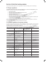
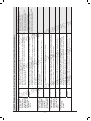
1
Dom_heat-2nd-edn-cover.qxd
2/12/08
11:22 am
Page 2
Published by NBS, part of RIBA Enterprises Ltd, and available from:
RIBA Bookshops Mail Order
15 Bonhill Street
London EC2P 2EA
Telephone orders/General enquiries: 020 7256 7222
Fax orders: 020 7374 2737
Email orders: [email protected]
Or subscribe online to access the latest Approved Documents, practical guides and Technical Handbooks at
www.thenbs.com/buildingregs
Domestic Heating Compliance Guide
RIBA Bookshops
66 Portland Place, London W1B 1AD. Telephone 020 7256 7222
113–115 Portland Street, Manchester M1 6DW. Telephone 0161 236 7691
Birmingham & Midland Institute, Margaret Street, Birmingham B3 3SP. Telephone 0121 233 2321
RSUA, 2 Mount Charles, Belfast BT7 1NZ. Telephone 028 9032 3760
Renew Rooms, 82 Wood Street, Liverpool L1 4DQ. Telephone 0151 707 4380
ISBN 978 1 85946 279 9
Stock code 67342
© Crown copyright 2008
Copyright in the typographical arrangement rests with the Crown.
This publication, excluding logos, may be reproduced free of charge in any format or
medium for research, private study or for internal circulation within an organisation.
This is subject to it being reproduced accurately and not used in a misleading context.
The material must be acknowledged as Crown copyright and the title of the publication
specified.
www.thenbs.com
This document/publication is value added. If you wish to re-use, please apply for a
Click-Use Licence for value added material at HYPERLINK http://www.opsi.gov.uk/clickuse/system/online/pLogin.asp www.opsi.gov.uk/click-use/system/online/pLogin.asp,
or by writing to the Office of Public Sector Information, Information Policy Team, Kew,
Richmond, Surrey TW9 4DU
December 2008
2nd Edition
N
O
SI
R
E
V
The Building Regulations 2000
As amended 2006
E
N
LI
ON
DOMESTIC HEATING COMPLIANCE GUIDE
N
O
SI
COMPLIANCE WITH APPROVED DOCUMENTS
L1A: NEW DWELLINGS AND L1B: EXISTING DWELLINGS
E
N
LI
ON
E
N
LI
ON
R
E
V
N
O
SI
R
E
V
Second edition December 2008
1
E
N
LI
ON
Published by NBS for Communities and Local Government
NBS is part of RIBA Enterprises Ltd.
N
O
SI
R
E
V
RIBA Bookshops Mail Order
15 Bonhill Street, London EC2P 2EA
Telephone orders/General enquiries: 020 7256 7222
Fax orders: 020 7374 2737
Email orders: [email protected]
Or order online at www.thenbs.com/buildingregs
N
O
SI
RIBA Bookshops
66 Portland Place, London W1B 1AD. Telephone 020 7256 7222
113–115 Portland Street, Manchester M1 6DW. Telephone 0161 236 7691
Birmingham & Midland Institute, Margaret Street, Birmingham B3 3SP. Telephone 0121 233 2321
RSUA, 2 Mount Charles, Belfast BT7 1NZ. Telephone 028 9032 3760
Renew Rooms, 82 Wood Street, Liverpool L1 4DQ. Telephone 0151 707 4380
R
E
V
Communities and Local Government Publications
PO Box 236
Wetherby
West Yorkshire
LS23 7NB
Tel: 08701 226 236
Fax: 08701 226 237
Textphone: 08701 207 405
Email: [email protected]
Online via the Communities and Local Government website: www.communities.gov.uk
E
N
LI
ON
Department for Communities and Local Government
Eland House
Bressenden Place
London
SW1E 5DU
Telephone: 020 7944 4400
Website: www.communities.gov.uk
E
N
LI
© Crown Copyright, 2008
ON
Stock code: 67342
ISBN: 978 1 85946 279 9
N
O
SI
R
E
V
First edition published May 2006
Second edition published December 2008
Copyright in the typographical arrangement rests with the Crown.
This publication, excluding logos, may be reproduced free of charge in any format or medium for research, private study or for
internal circulation within an organisation. This is subject to it being reproduced accurately and not used in a misleading context.
The material must be acknowledged as Crown copyright and the title of the publication specified.
This document/publication is value added. If you wish to re-use, please apply for a Click-Use Licence for value added material at
www.opsi.gov.uk/click-use/system/online/pLogin.asp, or by writing to the Office of Public Sector Information,
Information Policy Team, Kew, Richmond, Surrey TW9 4DU. Email: [email protected].
If you require this publication in an alternative format please email
[email protected].
2
Contents
Section 1
1.1 How to use this guide
1.2 Glossary
1.3The Building Regulations requirements and the guidance in
Approved Documents L1A and L1B
1.4 Replacement of primary heating appliances
1.5 Notification of building work
Section 2
N
O
SI
R
E
V
Gas-fired space heating and hot water systems
2.1 Scope of guidance
2.2 Gas-fired wet central heating systems
2.3 Gas-fired range cookers with integral central heating boiler
2.4 Gas-fired warm air heating
2.5 Gas-fired fixed independent space heating appliances
2.6 Gas-fired fixed decorative fuel-effect fires
2.7Gas fire for secondary space heating provided as part of a combined fire
and back boiler unit
E
N
LI
ON
Section 3
PAGE
4
Introduction
Oil-fired space heating and hot water systems
5
6
7
8
9
10
10
10
16
17
19
21
21
23
3.1 Scope of guidance
3.2 Oil-fired wet central heating systems
3.3 Oil-fired range cookers with integral central heating boilers
3.4Continually burning oil-fired vaporising appliances providing
secondary heating or hot water
3.5 Oil-fired fixed independent space heating appliances
S
R
VE
N
O
I
23
23
29
30
31
Section 4
4.1
4.2
4.3
Section 5
Electric heating systems
32
Scope of guidance
32
Electric boilers serving central heating systems in new and existing dwellings 32
Electric heating systems (other than central heating using electric boilers) 36
Solid fuel heating systems
38
Scope of guidance
Solid fuel appliances for primary heating
Central heating systems using certain types of solid fuel appliances
Solid fuel appliances for secondary heating
38
38
40
46
ON
5.1
5.2
5.3
5.4
Section 6
E
N
LI
Heat pump systems
ON
8.1 Scope of guidance
Section 9
Underfloor heating systems
7.1 Scope of guidance
Section 8
N
O
SI
Community heating systems
6.1 Scope of guidance
6.2 Definition of community heating
Section 7
E
N
LI
R
E
V
48
48
48
55
55
58
58
Solar water heating
62
9.1 Scope of guidance
62
Section 10 Individual domestic (micro) combined heat and power
68
Appendix A Assessing the case for a non-condensing boiler
69
3
Section 1 Introduction
Part L of Schedule 1 to the Building Regulations1 is concerned with the conservation of fuel and
power in buildings. For dwellings, Part L is supported by two Approved Documents, Approved
Document L1A (ADL1A) and Approved Document L1B (ADL1B). In addition to Part L, other
Building Regulations also bear on the energy performance of dwellings and their heating systems.
ADL1A gives guidance on how to satisfy the energy performance provisions of the Building
Regulations for new dwellings. ADL1B gives guidance on how to satisfy the energy performance
provisions of the Building Regulations for work in existing dwellings. Both Approved Documents
repeat the relevant regulatory requirements verbatim in various places, distinguished by a green
background, with the aim of making them complete references for ordinary purposes. In cases of
doubt, however, it may be necessary to refer directly to the Building Regulations as amended.
N
O
SI
R
E
V
ADL1A and ADL1B were published in 2006 in support of the amendment to the Building Regulations,
SI 2006/652. The amendment came into force on 6 April 2006.
E
N
LI
These new Approved Documents are more strategic in nature and rely on ‘second-tier’ documents to
provide detailed information on the minimum provisions necessary to comply with the requirements
of the Regulations.
ON
This Domestic Heating Compliance Guide is a second-tier document referred to in ADL1A and
ADL1B as a source of guidance on the means of complying with the requirements of the Building
Regulations for space heating systems and hot water systems. The guide was prepared with the
assistance of industry bodies. It covers conventional means of providing primary and secondary
space heating and domestic hot water for dwellings in use in England and Wales at the time of
writing.
N
O
SI
The guide identifies standards of provision that meet the requirements for systems in new build and
those in existing buildings when work is being undertaken.
R
E
V
For new dwellings, guidance is provided on the design limits for fixed building services referred to in
ADL1A. For existing dwellings, guidance is provided on reasonable provision for the installation or
replacement of controlled services as referred to in ADL1B.
E
N
LI
The levels of performance for new and existing dwellings differ only where practical constraints arise
in existing dwellings.
ON
Figure 1 Status of the Domestic Heating Compliance Guide
Legal requirements
in the Building
Regulations and
Part L of Schedule 1
1st Tier
2nd Tier
Approved Document
Part L 1A & 1B
Domestic Heating
Compliance Guide
3rd Tier
R
E
V
N
O
SI
Industry guides,
good practice guides,
codes of practice
and standards
The Domestic Heating Compliance Guide covers a range of frequently occurring situations but
alternative means of achieving compliance may be possible. The status of alternative provisions is
explained in the ‘Use of Guidance’ sections at the front of the Approved Documents.
E
N
LI
ON
The guide also refers to third-tier publications which include information on good practice for design
and installation over and above the minimum regulatory provision.
1
The Building Regulations, SI 2006:652, including Part L of Schedule 1, apply in England and Wales. Separate
regulations apply in Scotland and Northern Ireland and may require different provisions than those signalled in
this guide as the minimum regulatory requirement.
4
1.1 How to use this guide
The Domestic Heating Compliance Guide provides guidance on the means of complying with the
requirements of the Building Regulations Part L for conventional space heating systems and hot
water systems in dwellings.
The guide comprises four self-contained fuel-based sections and five specialist technology-specific
sections. Each fuel-based section addresses the requirements applicable to primary and secondary
space heating and hot water technologies for the particular fuel. The specialist technology-specific
sections provide further guidance on the minimum provisions for particular specialised space heating
and hot water technologies. The structure of the guide is illustrated in Figure 2 and is as follows:
•
•
N
O
SI
R
E
V
Fuel-based sections:
– Section 2: Gas-fired primary and secondary space heating and hot water
– Section 3: Oil-fired primary and secondary space heating and hot water
– Section 4: Electric primary and secondary space heating and hot water
– Section 5: Solid fuel primary and secondary space heating and hot water
Specialist technology-specific sections:
– Section 6: Community heating
– Section 7: Underfloor heating
– Section 8: Heat pumps
– Section 9: Solar water heating
– Section 10: Micro-CHP (Combined Heat and Power)
E
N
LI
ON
For any particular application, the relevant fuel-based section and/or specialist technology-specific
section must be read in conjunction with this introduction and the following generic sections:
N
O
SI
•
Section 1 Introduction
•
Section 1.1How to use this guide
•
Section 1.2 Glossary
•
Section 1.3The Building Regulations requirements and the guidance
in Approved Documents L1A and L1B
•
Section 1.4 Replacement of primary heating appliances
•
Section 1.5 Notification of building work
E
N
LI
ON
R
E
V
For each type of space heating or hot water system, guidance on the minimum provisions needed to
comply with Part L is supported by commentaries in italic font with a shaded background. These
commentaries are labelled ‘Supplementary Information’ and may be useful when interpreting the
minimum provisions and, in some cases, provide links to best practice guidance. They do not specify
minimum provisions.
N
O
SI
Figure 2 Structure of the Domestic Heating Compliance Guide
Section 1
Introduction
Section 1.1
How to use the guide
Section 1.2
Glossary
E
N
LI
ON
Section 1.3
Requirements and
guidance in Approved
Documents
L1A and L1B
Section 1.4
Replacement of
primary heating
appliances
Section 1.5
Notification of
building work
R
E
V
Section 2
Gas systems
Pages 10–22
Section 3
Oil systems
Pages 23–31
Section 4
Electric systems
Pages 32–37
Section 5
Solid fuel systems
Pages 38–47
5
Section 6
Community heating systems
Pages 48–54
Section 7
Underfloor heating systems
Pages 55–57
Section 8
Heat pump systems
Pages 58–61
Section 9
Solar hot water systems
Pages 62–67
Section 10
Micro-CHP systems
Page 68
Section 1.2 Glossary
Approved Document L1A ADL1AApproved Document L1A gives guidance on how to satisfy
the Building Regulations energy efficiency requirements when
building new dwellings. Effective from 6 April 2006.
Approved Document L1B
ADL1BApproved Document L1B gives guidance on how to satisfy
the Building Regulations energy efficiency requirements when
carrying out work in existing dwellings. Effective from 6 April
2006.
N
O
SI
The Building Regulations Statutory Instrument SI2000-531. The Building Regulations
ensure the health, safety, welfare and convenience of people
in and around buildings and reasonable provision for the
conservation of fuel and power and access to and use of
buildings by providing functional requirements for building
design and construction.
E
N
LI
ON
Department for Communities CLG
and Local Government
R
E
V
The government department responsible for
producing and revising the Building Regulations.
Domestic Heating
This second-tier document in support of Approved
Compliance GuideDocuments L1A and L1B sets out the minimum provisions for
all conventional space heating and hot water systems
provided in new dwellings and for work in existing dwellings
to comply with the Building Regulations energy efficiency
requirements.
N
O
SI
Minimum provisionIn this document ‘minimum provisions’ refers to the provisions
needed to demonstrate compliance of space heating and
hot water systems installed in dwellings with the Building
Regulations energy efficiency requirements.
E
N
LI
R
E
V
Supplementary informationThe commentaries labelled ‘Supplementary Information’ may
be useful when interpreting the minimum provisions and, in
some cases, provide links to best practice guidance.
ON
SAP 2005The Government’s Standard Assessment Procedure
for Energy Rating of Dwellings (2005 edition).
ON
E
N
LI
N
O
SI
R
E
V
6
Section 1.3 The Building Regulations requirements and the
guidance in Approved Documents L1A and L1B
The Building Regulations that bear on energy efficiency are repeated for easy reference at the front of
both Approved Document L1A and Approved Document L1B before the sections giving technical
guidance on compliance. The Approved Documents can be viewed at:
www.communities.gov.uk/planningandbuilding/buildingregulations/
N
O
SI
For new dwellings, the provision of heating and hot water services systems has to be considered as
part of the overall design of the building. For works on heating and hot water services systems in
existing dwellings, provision can be considered in isolation. Both Approved Documents refer to this
publication as the source of detailed guidance on what is reasonable provision.
E
N
LI
ON
E
N
LI
ON
ON
E
N
LI
R
E
V
N
O
SI
R
E
V
N
O
SI
R
E
V
7
Section 1.4 Replacement of primary heating appliances
In order to comply with the energy efficiency requirements of the Building Regulations, replacement
appliances providing primary space heating and/or hot water in existing dwellings should meet the
following conditions.
Replacement not involving fuel or energy switch
N
O
SI
Where the primary heating appliance is replaced by one using the same fuel or energy supply, the
(seasonal) efficiency of the new equipment should be:
R
E
V
a. as stated in the relevant fuel-based section of this guide; AND
b.not worse than two percentage points lower than the efficiency of the controlled service
being replaced. If the efficiency of the appliance to be replaced is not known, efficiency
values may be taken from Table 4a or 4b of SAP 2005.
E
N
LI
Replacement involving fuel or energy switch
ON
If the new heating appliance uses a different fuel, the efficiency of the new service should be
multiplied by the ratio of the CO2 emission factor of the fuel used in the service being replaced to that
of the fuel used in the new service, to obtain the carbon equivalent efficiency. The checks described
in paragraphs a and b above should then be made. The CO2 emission factors should be taken from
Table 12 of SAP 20052.
N
O
SI
The aim is to discourage replacement of an existing appliance by a significantly less carbon efficient
one.
Examples
R
E
V
1. An old oil-fired boiler with an efficiency of 72% is to be replaced by a dual solid fuel boiler with an
efficiency of 65% as required by paragraph a above and Table 16.
E
N
LI
The carbon equivalent efficiency of the dual solid fuel boiler should be greater than 70% to meet the
requirement in paragraph b above. Its carbon equivalent efficiency is actually:
ON
65% × (0.265 ÷ 0.187) = 92.1%
where 0.265 and 0.187 kg CO2/kWh are the emission factors for oil and dual fuel appliances respectively.
2. An LPG-fired boiler of 81% efficiency is to be replaced with an oil boiler. The new oil boiler should
have:
N
O
SI
a. an efficiency of not less than 86% (see Table 9); and
b.a carbon equivalent efficiency greater than 79% (the efficiency of the existing LPG boiler less
2 percentage points).
E
N
LI
R
E
V
The efficiency of the proposed new oil boiler should therefore be greater than
79% ÷ (0.234 ÷ 0.265) = 79% ÷ 0.883 = 89.5%
ON
where 0.234 and 0.265 kg CO2/kWh are the emission factors of LPG and oil respectively.
2
The relevant column in Table 12 of SAP 2005 is the one entitled ‘Emissions, kg CO2/kWh.’
8
Section 1.5 Notification of building work
Work covered by requirement L1 in the 2006 amendment of Part L must make reasonable provision
to achieve energy efficiency. In most instances, this will require the building control body to be
notified of the intended work before the work commences, either by deposit of full plans or by a
building notice. The execution of the work is then subject to checking and inspections by the building
control body, with a completion certificate being issued on satisfactory completion of the work. In
certain situations, other procedures apply. These include:
N
O
SI
a. Where the work is being carried out under the terms of an authorised Competent Person (CP)
self-certification scheme, no advance notification to the building control body is needed. At the
completion of the work, the registered CP provides the building owner with a certificate
confirming that the installation has been carried out in accordance with the requirements of the
relevant regulations, and the scheme operator notifies the local authority to that effect.
E
N
LI
R
E
V
b. Where the work involves an emergency repair, e.g. a failed boiler or a leaking hot water
cylinder, there is no need to delay making the repair in order to make an advance notification to
the building control body. However, in such cases it will still be necessary for the work to comply
with the requirements and to give a notice to the building control body at the earliest
opportunity, unless an installer registered under an appropriate CP scheme carries out the work.
A completion certificate can then be issued in the normal way.
ON
c. Where the work is of a minor nature as detailed in Schedule 2B of the Building Regulations
(see page 14 of ADL1B), the work must comply with the relevant requirements, but need not be
notified to building control.
E
N
LI
ON
ON
E
N
LI
N
O
SI
R
E
V
N
O
SI
R
E
V
9
Section 2: Gas-fired space heating and hot water systems
This section provides guidance on the specification of gas-fired space heating and hot water systems
in dwellings.
All gas appliances must be installed by a competent person in accordance with the current issue of
the Gas Safety (Installation and Use) Regulations. The installation should follow the manufacturer’s
instructions and should comply with all other relevant parts of the Building Regulations and, for wet
systems, the Water Regulations.
2.1 Scope of guidance
N
O
SI
R
E
V
The guidance in this section applies to systems fuelled by natural gas and liquid petroleum gas (LPG);
any requirements specific to either fuel type are identified.
E
N
LI
The following types of gas-fired heating systems are addressed:
•
•
•
•
Wet central heating systems
Range cookers with integral central heating boilers
Warm-air heating systems
Fixed independent space heating devices
ON
Where appropriate, it may be necessary to refer to other sections in this guide covering community
heating, underfloor heating, heat pumps, solar water heating and micro-CHP.
N
O
SI
2.2 Gas-fired wet central heating systems
This section provides guidance on the specification of gas-fired wet central heating systems for
dwellings that, if followed, will satisfy the requirements of Part L of the Building Regulations.
R
E
V
Terminology and applicability of guidance to different scenarios in new and
existing dwellings
E
N
LI
The guidance in this section applies to the following situations:
ON
a. The specification of central heating systems in new dwellings – this situation is referred to in
this section as a new system.
b. The specification of central heating systems in existing dwellings where previously space
heating was not provided by central heating – this situation is also referred to in this section as a
new system.
N
O
SI
c. The specification of a replacement central heating system and/or component in existing
dwellings where central heating is already installed – this situation is referred to in this section as
a replacement system.
R
E
V
In situations (a) and (b) above the guidance for compliance of new systems (in new and existing
dwellings) with Part L is the same.
E
N
LI
In situation (c) above, that is for replacement systems in existing dwellings, in most cases the
guidance for compliance with Part L is as for new systems, unless otherwise stated in the relevant
section.
ON
In order to comply with the requirements of Part L, gas-fired central heating systems which are
provided as new systems or replacement systems in dwellings should meet the following
conditions:
a. The boiler should have a minimum efficiency (as defined by its SEDBUK value) as given in
Table 1 (row a); AND
b. The minimum provisions for system circulation as given in Table 1 (row b) need to be met;
AND
10
c. The minimum provisions for hot water storage and labelling of storage vessels as given in
Table 1 (row c) need to be met; AND
d. The minimum provisions for system preparation and water treatment as given in Table 1
(row d) should be met; AND
e. The system should be commissioned in accordance with the minimum provisions given in
Table 1 (row e); AND
N
O
SI
f. The minimum provisions for boiler interlock, zoning and time control and temperature control
of the heating and hot water circuits as described in Table 2 should be met. An acceptable
alternative to these is any boiler management system that delivers the specified zoning, timing
and temperature and boiler interlock control provisions. When gas boilers are installed as part of
a replacement system, the minimum level of system controls should be provided, as described
in Table 2, unless they are already installed and fully operational. If an individual component of
the control system is being replaced in an existing system, for example a room thermostat, it is
not necessary to upgrade the system to meet the minimum requirements; AND
E
N
LI
R
E
V
g. Pipework should be insulated as described in Table 3.
ON
E
N
LI
ON
ON
E
N
LI
N
O
SI
R
E
V
N
O
SI
R
E
V
11
ON
a.The boiler efficiency should be not less than 86% (SEDBUK
value); OR
b.In existing dwellings, in the exceptional circumstances defined in
Appendix A of this document, the boiler efficiency (SEDBUK
value) should be not less than 78% if natural gas-fired, or not less
than 80% if LPG-fired; OR
c.The boiler efficiency for heating boilers that are combined with
range cookers should be as defined in Section 2.3, ‘Gas-fired
range cookers with central heating boilers for space heating and
hot water’.
ON
Minimum provision for replacement systems
in existing dwellings
Replacements not involving a fuel or energy
switch
The seasonal efficiency of the new equipment
should be:
• as defined for new systems; AND
• not worse than two percentage points lower
than the seasonal efficiency of the controlled
service being replaced. If the efficiency of the
system or appliance to be replaced is not
known, efficiency values may be taken from
Table 4a or 4b of SAP 2005.
Replacement involving fuel or energy switch
If the new heating system or heat generating
appliance uses a different fuel, the efficiency of
the new service should be multiplied by the ratio
of the CO2 emission factor of the fuel used in the
service being replaced to that used in the new
service before making this check. The CO2
emission factors should be taken from
Table 12 of SAP 2005 (the column headed
‘Emissions kg CO2 per kWh’).
E
N
LI
R
E
V
a.Systems for space heating and domestic hot water primary
circuits should have fully pumped circulation.
b.If the boiler manufacturer’s instructions advise installation of a
bypass, an automatic bypass valve should be provided in
conjunction with any requirements for a minimum pipe length
specified in the manufacturer’s instructions.
E
N
LI
b. System
circulation
a. Minimum
acceptable
efficiency
Minimum provision for new systems in new and existing
dwellings
Guidance on identifying the SEDBUK
efficiency for an appliance
The Boiler Efficiency Database is available online
(www.boilers.org.uk) and includes regularly
updated information on most available boilers as
well as many which are no longer in production.
Manufacturers’ literature provides SEDBUK
values in an agreed form of words to avoid
confusion with other efficiency values.
Manufacturers will also supply SEDBUK values
for their products on request.
Supplementary information
Table 1 Minimum provisions for boiler efficiency, system circulation, hot water storage, system preparation and commissioning of
gas-fired central heating
ON
Appendix A gives the approved procedure for
establishing where exceptional circumstances
exist, as set out in the Guide to the Condensing
Boiler Installation Assessment Procedure for
Dwellings.
E
N
LI
R
E
V
12
As defined for new systems. When boilers are
replaced, existing systems with semi-gravity
circulation should be converted to fully pumped
circulation.
R
E
V
N
O
SI
N
O
SI
N
O
SI
ON
Minimum provision for new systems in new and existing
dwellings
Table 1 (continued)
a.Vented copper hot water storage vessels should comply with the
heat loss and heat exchanger requirements of BS 1566:2002.
b.Unvented hot water storage system products should:
i.comply with BS EN 12897; OR
ii.be certified by the British Board of Agrément, the Water
Research Council; OR
iii.be certified by another accredited body as complying with the
Building Regulations.
c.Primary storage systems should meet the insulation requirements
of sections 4.3.1 or 4.3.2 of the Water Heater Manufacturers’
Association performance specifications for thermal stores.
d.Combination cylinders should comply with BS 3198 and in
addition have a heat loss not exceeding 1.6 × [0.2 + 0.51V2/3]
kWh/day where V is the volume of the hot water part of the cylinder.
e.All hot water storage vessels should carry a label with the
following information:
• type of vessel
• nominal capacity in litres
• standing heat loss in kWh/day
• heat exchanger performance in kW
• vented copper hot water cylinders should carry clear labelling
on the product such as a BSI Kitemark, registered firm status
or reference to an equivalent quality control scheme
• vented cylinders that are not of copper construction should be
labelled as complying with the heat loss and heat exchanger
requirements of BS 1566.
a.Central heating systems should be thoroughly cleaned and
flushed out before installing a new boiler.
b.During final filling of the system, a chemical water treatment
formulation should be added to the primary circuit to control
corrosion and the formation of scale and sludge. Reasonable
provision would be to follow the guidance on how to prepare and
commission systems given in BS 7593.
c.Installers should also refer to the boiler manufacturer’s installation
instructions for appropriate treatment products and special
requirements for individual boiler models.
d.Where the mains total water hardness exceeds 200 parts per
million, provision should be made to treat the feed water to water
heaters and the hot water circuit of combination boilers to reduce
the rate of accumulation of limescale.
d. System
preparation
and water
treatment
ON
c. Hot water
storage
As defined for new systems.
Minimum provision for replacement systems
in existing dwellings
E
N
LI
E
N
LI
N
O
SI
R
E
V
R
E
V
13
As defined for new systems.
ON
Water Heater Manufacturers’ Association
Performance Specification for Thermal
Stores. www.waterheating.fsnet.co.uk/wma.htm
Insulation of primary stores
Due to the higher than normal storage
temperatures in primary stores it is very
important that these are well insulated.
Supplementary information
British Standards
BS 1566:2002 Copper indirect cylinders for
domestic purposes. Open vented copper
cylinders. Requirements and test methods.
BS EN 12897 Water supply. Specification for
indirectly heated unvented (closed) storage water
heaters.
E
N
LI
R
E
V
Note should also be made of the manufacturer’s
instructions for advice on appropriate action.
British Standards
BS 7593:2006 Code of practice for treatment of
water in domestic hot water central heating
systems.
N
O
SI
N
O
SI
e. Commissioning
Minimum provision for new systems in new and existing dwellings
Table 1 (continued)
ON
ON
a.On completion of the installation of a boiler or a hot water storage
system, together with associated equipment such as pipework,
pumps and controls, the equipment should be commissioned in
accordance with the manufacturer’s instructions. These
instructions will be specific to the particular boiler and/or hot
water storage system.
b.The installer should give a full explanation of the system and its
operation to the user, including the manufacturer’s user manual
where provided.
c.Once the installation of a gas-fired boiler is complete, the CORGI
installer should notify CORGI, who will send a Building
Regulations Compliance Certificate to the builder, or householder
in the case of work in an existing dwelling, and notify building
control on their behalf.
d.If not registered with a ‘Competent Person’ scheme for the
purposes of self-certifying compliance with the Building
Regulations, the installer or the person commissioning the work
should notify building control prior to the commencement of the
work.
As defined for new systems.
Minimum provision for replacement systems
in existing dwellings
ON
The Benchmark System
• The Benchmark Commissioning Checklist can
be used to show that commissioning has been
carried out satisfactorily. Benchmark licenceholders provide a checklist with the appliance
for completion by the persons commissioning
the system so that they can record that all the
checks have been made and the results show
efficient operation of the equipment in
compliance with Part L. The Benchmark
checklist should be provided to the builder, or
the householder in the case of work in existing
dwellings, an appointed agent or the end user.
• A Benchmark Commissioning Checklist will be
included in all HHIC gas boiler manufacturer
members’ installation manuals to help installers
record information about the installation in
order to assist with servicing and repairs. For
example, details of system cleaners and
inhibitors can be recorded.
• Only manufacturing companies who hold a
Benchmark licence will be eligible to use the
Benchmark logo and the approved log book
wording and layout. (Benchmark is registered
as a European Collective Mark by the Heating
and Hotwater Information Council Ltd, and the
content is copyright.)
Supplementary information
E
N
LI
E
N
LI
E
N
LI
N
O
SI
R
E
V
N
O
SI
R
E
V
R
E
V
14
N
O
SI
As defined for new systems.
As defined for new systems unless only the
hot water cylinder is being replaced and
separate time control for the hot water circuit
is not present. In this case it is acceptable to
have a single timing control for both space
heating and hot water.
• Dwellings with a total usable floor area up to 150m2 should be divided into at least two space heating zones with
independent temperature control, one of which is assigned to the living area.
• Dwellings with a total usable floor area greater than 150m2 should be provided with at least two space heating
zones, each having separate timing and temperature controls.
• Single-storey open-plan dwellings in which the living area is greater than 70% of the total floor area –
sub‑zoning of temperature control is not appropriate.
• All dwellings should have a separate hot water zone in addition to space heating zones.
• A separate hot water zone is not required if the hot water is produced instantaneously, such as with a combination
boiler.
Time control of space and water heating should be provided by:
i. a full programmer with separate timing to each circuit; OR
ii. two or more separate timers providing timing control to each circuit; OR
iii. programmable room thermostat(s) to the heating circuit(s), with separate timing of the hot water circuit.
For dwellings with a total usable floor area greater than 150m2 timing of the separate space heating zones can be
achieved by:
i. multiple heating zone programmers; OR
ii. a single multi-channel programmer; OR
iii. programmable room thermostats; OR
iv. separate timers to each circuit; OR
v. a combination of (iii) and (iv) above.
Where the hot water is produced instantaneously, such as with a combination boiler, time control is only required for
space heating zones.
Separate temperature control of zones within the dwelling should be provided using:
i. Room thermostats or programmable room thermostats in all zones; OR
ii. A room thermostat or programmable room thermostat in the main zone, and individual radiator controls such as
thermostatic radiator valves (TRVs) on all radiators in the other zones; OR
iii. a combination of (i) and (ii) above.
• D
omestic hot water systems should be provided with a cylinder thermostat and a zone valve or three-port valve to
control the temperature of stored hot water.
• In dwellings with a total floor area greater than 150m2 it could be reasonable to provide more than one hot water
circuit each having separate timing and temperature controls. This can be achieved by:
i. multiple heating zone programmers; OR
ii. a single multi-channel programmer; OR
iii. separate timers to each circuit.
• The use of non-electric hot water controllers does not meet this requirement. Also, in some circumstances, such as
thermal stores, a zone valve is not appropriate; a second pump could be substituted for the zone valve.
Space heating
zones
Water heating
zones
Time control of
space and water
heating
Temperature
control of space
heating
Temperature
control of
domestic
hot water
Minimum provision for replacement systems
• Boiler-based systems should have boiler control interlock in which controls are wired so that when there is no
demand for either space heating or hot water, the boiler and pump are switched off.
• The use of thermostatic radiator valves (TRVs) alone does not provide interlock.
Boiler interlock
As defined for new systems, except where
the boiler only is replaced reasonable
provision for a space heating system would
be to control as one zone.
As defined for new systems.
Minimum provision for new systems
System control
Table 2 Minimum provisions for control of gas-fired central heating systems*
ON
ON
ON
E
N
LI
E
N
LI
15
R
E
V
N
O
SI
R
E
V
N
O
SI
*An acceptable alternative to these controls is any boiler management control system that meets the specified zoning, timing and temperature and boiler interlock control requirements.
Supplementary information
More details on control systems can be found in manufacturers’ literature and on the The Association of Controls Manufacturers (TACMA) website www.heatingcontrols.org.uk
As defined for new systems for planned
replacement of hot water cylinders on all fully
pumped installations and on gravity
circulation installations.
In exceptional circumstances, such as
emergency replacement or where the cylinder
or installation is of a type that precludes the
fitting of electric controls, a thermomechanical cylinder thermostat should be
installed as a minimum provision.
As defined for new systems.
E
N
LI
R
E
V
N
O
SI
Table 3 Minimum provisions for insulation of pipes serving gas-fired central
heating systems
Minimum provision
Supplementary information
In new systems pipes should be insulated to comply
with the maximum permissible heat loss indicated in
the Supplementary Information column, and labelled
accordingly, as follows:
Insulation for pipework in unheated areas
Extra provision may need to be made to protect
central heating and hot water pipework in unheated
areas against freezing. Further guidance is available in:
• BS 5422:2001 Method for specifying thermal
insulating materials for pipes, tanks, vessels,
ductwork and equipment operating within the
temperature range of –40°C to +700°C.
• BRE Report No 262 Thermal insulation: avoiding
risks, 2002 Edition.
• Primary circulation pipes for heating and hot water
circuits should be insulated wherever they pass
outside the heated living space or through voids
which communicate with and are ventilated from
unheated spaces.
• Primary circulation pipes for domestic hot water
circuits should be insulated throughout their length,
subject only to practical constraints imposed by the
need to penetrate joists and other structural
elements.
• All pipes connected to hot water storage vessels,
including the vent pipe, should be insulated for at
least 1 metre from their points of connection to the
cylinder (or they should be insulated up to the point
where they become concealed).
• If secondary circulation is used, all pipes kept hot
by that circulation should be insulated.
E
N
LI
ON
R
E
V
For replacement systems, whenever a boiler or hot
water storage vessel is replaced in an existing system,
any pipes that are exposed as part of the work or are
otherwise accessible should be insulated as
recommended above – or to some lesser standard
where practical constraints dictate.
E
N
LI
ON
N
O
SI
Where insulation is labelled as complying with the
Domestic Heating Compliance Guide it must not
exceed the following heat loss levels:
Pipe diameter (OD)
mm
Maximum permissible
heat loss*
(W/m)
8
7.06
10
7.23
12
7.35
N
O
SI
15
22
7.89
R
E
V
9.12
28
35
10.07
42
11.08
54
12.19
14.12
*In assessing the thickness of insulation required to
meet the provision, standardised conditions should be
used in all compliance calculations based, in this
instance, on a horizontal pipe at 60°C in still air at 15°C.
Further assistance in converting these heat loss limits
to levels (thickness) of insulation for specific thermal
conductivities is found in the ‘TIMSA HVAC Guidance
for Achieving Compliance with Part L of the Building
Regulations’.
N
O
SI
R
E
V
2.3 Gas-fired range cookers with integral central heating boiler
This section provides guidance on the specification of gas-fired range cookers with integral central
heating boilers for space heating and hot water in dwellings.
E
N
LI
In order to comply with the requirements of Part L, gas-fired range cookers with an integral central
heating boiler which are provided in new or existing dwellings should meet the following conditions:
ON
a. The appliance should have two independently controlled burners (one for the cooking
function and one for the boiler); AND
b. The boiler should have a Seasonal Efficiency (SEDBUK3) value in excess of 75%. The
manufacturer’s declaration of appliance performance and SEDBUK value should include the
following words:
3
SEDBUK efficiency values can be found in the Government’s Standard Assessment Procedure for Energy
Rating of Dwellings (2005 edition) www.bre.co.uk/sap2005
16
•
•
•
•
Seasonal Efficiency (SEDBUK) = xx %
Case heat emission value = yy kW
Heat transfer to water at full load = zz kW
The values are used in the UK Government’s Standard Assessment Procedure (SAP) for the
energy rating of dwellings. The test data from which they have been calculated has been
certified by {insert name and/or identification of Notified Body}.
AND
N
O
SI
c. The minimum provisions for gas-fired central heating systems should be met with respect to
the integral central heating boilers as given in Table 1 (rows B–E); AND
R
E
V
d. The minimum provisions for boiler interlock, zoning and time control and temperature control
of the heating and hot water circuits should be met with respect to the integral central heating
boilers as given in Table 2 for gas-fired central heating systems. An acceptable alternative to
these is any boiler management system that delivers the specified zoning, timing and
temperature provisions. When gas boilers are installed as a replacement for existing boilers, the
minimum level of system controls should be provided, as described in Table 2, unless they are
already installed and fully operational. If an individual component of the control system is being
replaced in an existing system, for example a room thermostat, it is not necessary to upgrade
the system to meet the minimum requirements; AND
E
N
LI
ON
e. Pipework should be insulated as described in Table 3.
2.4 Gas-fired warm air heating
N
O
SI
This section provides guidance on the specification of gas-fired warm air heating systems for
dwellings.
R
E
V
Terminology and applicability of guidance to different scenarios in new and
existing dwellings
E
N
LI
The guidance in this section applies to the following situations:
a. The specification of gas-fired warm air heating systems in new dwellings – this situation is
referred to in this section as a new system.
ON
b. The specification of gas-fired warm air heating systems in existing dwellings where previously
space heating was not provided by a warm air system – this situation is also referred to in this
section as a new system.
c. The specification of a replacement warm air heating system and/or component in existing
dwellings where warm air heating is already installed – this situation is referred to in this section
as a replacement system.
N
O
SI
In order to comply with the energy efficiency requirements of the Building Regulations, gas-fired
warm air heating which is provided as a new system or replacement system in new or existing
dwellings should meet the following conditions:
E
N
LI
R
E
V
a. The system should meet the provisions for efficiency and installation set out in Table 4; AND
b. The system should be zoned and incorporate the timing and temperature controls for
space heating and, where relevant, domestic hot water, as set out in Table 5.
ON
17
Table 4 Minimum provisions for efficiency and installation of gas-fired warm
air heating systems
Efficiency
Minimum provision
Supplementary information
a. Gas-fired warm air units should meet the
requirements, as appropriate to the design of the
appliance, of:
• BS EN 778: 1998; OR
• BS EN 1319: 1999.
British standards
BS EN 778:1998 Domestic gas-fired
forced convection air heaters for
space heating not exceeding a net
heat input of 70 kW, without a fan to
assist transportation of combustion
air and/or combustion products.
N
O
SI
b. If a gas-fired circulator is incorporated in the
warm air unit to provide domestic hot water, it
should be able to deliver full and part load efficiency BS EN 1319:1999 Domestic gas‑fired
forced convection air heaters for
at least equal to that prescribed by BS EN 483.
space heating, with fan‑assisted
burners not exceeding a net heat
c. The manufacturer’s declaration of appliance
input of 70 kW.
performance should include the following words:
E
N
LI
R
E
V
Combined warm air unit and circulator
This product has been assessed against the test
methods set out in BS EN 778:1998* or
BS EN 1319:1999* {*deleted as appropriate} and
BS EN 483*, and certified as meeting those minimum
requirements by {insert name and/or identification of
Notified Body}.
ON
BS EN 483:2000 Gas-fired central
heating boilers. Type C boilers of
nominal heat input not exceeding
70kW.
N
O
SI
Warm air unit alone
This product has been assessed against the test
method set out in BS EN 778:1998* or
BS EN 1319:1999* {*deleted as appropriate} and
certified as meeting the minimum requirements by
{insert name and/or identification of Notified Body}.
Installation
R
E
V
a. The system should be installed in accordance with
BS 5864:2004.
E
N
LI
b. Ductwork that is newly installed or replaced should
be insulated in accordance with the
recommendations of BS 5422:2001.
ON
ON
E
N
LI
BS 5864:2004 Installation and
maintenance of gas-fired ducted air
heaters of rated input not exceeding
70 kW net (second and third family
gases). Specification.
BS 5422:2001 Method for specifying
thermal insulating materials for pipes,
tanks, vessels, ductwork and
equipment operating within the
temperature range of –40°C to
+700°C
N
O
SI
R
E
V
18
Table 5 Minimum provisions for system controls for gas-fired warm air heating
System
Minimum provision
Warm air systems i. Time and
without water
temperature
heating
control
ii. Zoning
Time and temperature control should be provided by either:
i.Controls external to heater: time switch/programmer and room
thermostat, or programmable room thermostat; OR
ii.Controls integrated in the heater – time-switch/programmer and
room temperature sensor linked to heater firing and fan speed
control.
E
N
LI
ON
N
O
SI
• New dwellings with a total usable floor area up to 150m2
should be divided into at least two space heating zones with
independent timing controls, one of which is assigned to the living
area.
• New dwellings with a total usable floor area greater than 150m2
should be provided with at least two space heating zones, each
having separate timing and temperature controls. Timing of the
separate space heating zones can be achieved by:
i. multiple heating zone programmers; OR
ii. a single multi-channel programmer; OR
iii.programmable room thermostats; OR
iv.separate timers to each circuit; OR
v. a combination of (iii) and (iv) above.
R
E
V
The provisions for zoning for replacement systems in existing
dwellings should be as for new dwellings where practical.
iii. Independent time control of both the heating and hot water circuits
Combined warm
air and domestic
hot water systems iv. Pumped primary circulation to the hot water cylinder
for installations
v. Independent
a. For new systems: Independent control of the hot water circuit
control of
should be achieved by means of a cylinder thermostat and a
hot water
timing device, wired such that when there is no demand for hot
production
water both the pump and the circulator are switched off.
b. For replacement systems: Independent control of the hot water
circuit should be achieved, where practicable, for circulator water
heaters of less than 6kW output by means of a cylinder thermostat
and a timing device, wired such that when there is no demand for
hot water both the pump and the circulator are switched off.
E
N
LI
ON
vi. Time control
N
O
SI
R
E
V
Time control should be provided by use of either:
• A full programmer with separate timing to each circuit; OR
• Two or more separate timers providing timing control to each
circuit; OR
• Programmable room thermostat(s) to the heating circuit(s), with
separate timing of the hot water; OR
• A time switch/programmer (two-channel) and room thermostat.
vii.Space heating
zoning
E
N
LI
ON
N
O
SI
• New dwellings with a total usable floor area up to 150m2
should be divided into at least two space heating zones with
independent timing controls, one of which is assigned to the living
area.
• New dwellings with a total usable floor area greater than 150m2
should be provided with at least two space heating zones, each
having separate timing and temperature controls.
R
E
V
The provisions for zoning for replacement systems in existing
dwellings should be as for new dwellings where practical.
2.5 Gas-fired fixed independent space heating appliances
This section provides guidance on the specification of gas-fired fixed independent space heating
appliances for dwellings.
Fixed independent space heating appliances may be installed as a means of primary or secondary
space heating.
19
Gas-fired fixed independent appliances for primary space heating
In order to comply with the Building Regulations energy efficiency requirements, gas-fired fixed
independent space heating appliances in new and existing dwellings which are provided as the
primary heat source should meet the following conditions:
a. The appliance should be one of the types described in Table 6; AND
b. The efficiency of the appliance (gross calorific value) should be no less than 58%. The
appliance manufacturer’s declaration of appliance performance shall include the following
words:
N
O
SI
R
E
V
The efficiency of this appliance has been measured as specified in {insert appropriate entry from
Table 6} and the result is [x]%. The gross calorific value of the fuel has been used for this
efficiency calculation. The test data from which it has been calculated has been certified by
{insert name and/or identification of Notified Body}. The efficiency value may be used in the UK
Government’s Standard Assessment Procedure (SAP) for energy rating of dwellings.
E
N
LI
AND
ON
c. In new dwellings, each appliance should be capable, either independently or in conjunction
with room thermostats or other suitable temperature sensing devices, of controlling the
temperatures independently in areas that have different heating needs (e.g. separate sleeping
and living areas). In existing dwellings, wherever practical, temperature controls should be
upgraded to the standards required for new dwellings.
N
O
SI
Table 6 Acceptable appliance types for fixed natural gas and LPG gas-fired
space heaters for use as a primary heat source
British Standard designation (appliance type)
R
E
V
BS EN 1266:2002 Independent gas-fired convection heaters incorporating a fan to assist transportation of
combustion air and/or flue gases.
E
N
LI
BS 7977-1:2002 Specification for safety and rational use of energy of domestic gas appliances. Radiant/convectors.
BS EN 613:2001 Independent gas-fired convection heaters.
ON
BS EN 13278:2003 Open fronted gas-fired independent space heaters.
Gas-fired fixed independent appliances for secondary space heating
In order to comply with the requirements of Part L, gas-fired fixed independent space heating
appliances which are provided as the secondary heat source in new or existing dwellings should
meet the following conditions:
N
O
SI
a. The appliance should be one of the types described in Table 7; AND
R
E
V
b. The efficiency (gross calorific value) of the appliance should be no less than the value in Table
7 for that type of appliance. The appliance manufacturer’s declaration of appliance performance
shall include the following words:
E
N
LI
The efficiency of this appliance has been measured as specified in {insert appropriate entry from
Table 7} and the result is [x]%. The gross calorific value of the fuel has been used for this
efficiency calculation. The test data from which it has been calculated has been certified by
{insert name and/or identification of Notified Body}. The efficiency value may be used in the UK
Government’s Standard Assessment Procedure (SAP) for energy rating of dwellings.
ON
20
Table 7 Acceptable appliance types and minimum appliance efficiencies for
independent fixed natural gas and LPG gas-fired space heaters used as a
secondary heat source
British Standard designation (appliance type)
Minimum efficiency %
(gross calorific value)
Gas
BS EN 1266:2002 Independent gas-fired convection heaters incorporating
a fan to assist transportation of combustion air and/or flue gases.
72
S
R
VE
LPG
N
O
I
73
(All types except inset live fuel effect)
BS 7977-1:2002 Specification for safety and rational use of energy of
domestic gas appliances. Radiant/convectors.
63
BS EN 613:2001 Independent gas-fired convection heaters.
58
BS EN 13278:2003 Open fronted gas-fired independent space heaters.
45
46
(Inset live fuel-effect)
BS 7977-1:2002 Specification for safety and rational use of energy of
domestic gas appliances. Radiant/convectors.
40
41
E
N
LI
ON
(Flue-less)
prEN 148294:2003 (Draft) Independent gas-fired flueless space heaters
for nominal heat input not exceeding 6 kW.
(Flue-less)
BS EN 449:2002 Specification for dedicated liquefied petroleum gas
appliances. Domestic flueless space heaters (including diffusive
catalytic combustion heaters).
60
Thermal efficiency requirements for
this type of appliance are not
specified as all the heat produced by
the combustion process is released
into the space to be heated. In SAP
2005 the efficiency of these
appliances is classed as 90% and an
adjustment is made for ventilation in
the space heating requirement
calculation.
N
O
SI
R
E
V
2.6 Gas-fired fixed decorative fuel-effect fires
E
N
LI
64
This type of appliance is intended for decorative purposes and therefore a minimum thermal
efficiency is not specified. Note that for the purposes of SAP 2005 the efficiency of decorative
fuel‑effect fires is classed as 20% for use in the space heating requirement calculation. See Table 4a
of SAP 2005.
ON
In order to comply with the requirements of Part L, gas-fired decorative fires in new and existing
dwellings should meet the following conditions:
a. The appliance should meet the product standards specified in BS EN 509:2000 Decorative
fuel-effect gas appliances; AND
N
O
SI
b. No more than one appliance should be installed per 100m2 of dwelling floor area.
R
E
V
2.7 Gas fire for secondary space heating provided as part of a
combined fire and back boiler unit
E
N
LI
A combined fire and back boiler unit can only be installed as a replacement for an existing combined
fire and back boiler unit, and then only when the criteria of the Condensing Boiler Installation
Assessment Procedure are satisfied as outlined in Appendix A of this document. In order to comply
with the requirements of the Building Regulations, the gas fire provided as a secondary heat source
as part of a combined fire and back boiler unit, when provided as a replacement system in existing
dwellings, should meet the following conditions:
ON
4
At the time of writing prEN 14829 is in draft but it may not appear as a European standard. The type of
appliance for which this standard is proposed is on the market having been certified as complying with the
essential requirements of the Gas Appliance Directive. The BSI is producing a parallel UK safety installation
standard for appliances designed to comply with prEN 14829.
21
a. The appliance should be one of the types described in Table 8; the appliance manufacturer’s
declaration of appliance performance shall include the following words:
The efficiency of this appliance has been measured as specified in {insert appropriate entry from
Table 8} and the result is [x]%. The gross calorific value of the fuel has been used for this
efficiency calculation. The test data from which it has been calculated has been certified by
{insert name and/or identification of Notified Body}. The efficiency value may be used in the UK
Government’s Standard Assessment Procedure (SAP) for energy rating of dwellings.
N
O
SI
AND
b. The efficiency (gross calorific value) of the appliance should be no less than the value in
Table 8 for that type of appliance.
R
E
V
Table 8 Minimum appliance efficiencies for gas fires used with back boilers
E
N
LI
British Standard designation (appliance type)
ON
Minimum efficiency %
(Gross Calorific Value)
Natural gas
LPG
(Inset live fuel-effect)
BS 7977-2:2003 Specification for safety and rational use of energy of
domestic gas appliances. Combined appliances. Gas fire/back boiler
40
41
(All types except inset live fuel-effect)
BS 7977-2:2003 Specification for safety and rational use of energy of
domestic gas appliances. Combined appliances. Gas fire/back boiler
63
64
N
O
SI
Supplementary information – further guidance on gas-fired heating
R
E
V
Further guidance on gas-fired heating systems is available in the following publications:
Energy Efficiency Best Practice in Housing publications
• CE30 Domestic heating by gas boiler systems
• CE51 Central heating system specifications (CHeSS)
• CE54 Whole house boiler sizing method for houses and flats
E
N
LI
ON
SBGI publications on gas boilers and gas fires under development at the time of writing.
See www.sbgi.org.uk for updates.
CORGI publications
• Essential Gas Safety (GID1)
• Gas Cookers and Ranges (GID2)
• Gas Fires and Space Heaters (GID3)
• Water Heaters (GID5)
• Central Heating – Wet and Dry (GID7)
• Wet Central Heating System Design Guide (WCH1)
• Warm Air Heating System Design Guide (WAH1)
R
E
V
N
O
SI
Requirements relating to various aspects of the installation of condensing boilers are given in British
Standards, BS 5440 Parts 1 and 2, BS 5449 and BS 6798.
ON
E
N
LI
22
Section 3: Oil-fired space heating and hot water systems
This section provides guidance on the specification of oil-fired space heating and hot water systems
in dwellings to meet the Building Regulations energy efficiency requirements.
All oil appliances must be installed by a competent person and the installation should follow the
manufacturer’s instructions and comply with all other relevant parts of the Building Regulations and,
for wet systems, the Water Regulations.
N
O
SI
3.1 Scope of guidance
R
E
V
The guidance in this section applies to systems fuelled by oil. The following types of oil-fired heating
systems are addressed:
•
•
•
•
Wet central heating systems
Range cookers with integral central heating boilers
Vaporising appliances providing secondary heating or hot water
Fixed independent space heating devices
E
N
LI
ON
Where appropriate, it may be necessary to refer to the sections in this guide covering community
heating, under-floor heating, heat pumps, solar water heating and micro-CHP.
3.2 Oil-fired wet central heating systems
This section provides guidance on the specification of oil-fired wet central heating systems for
dwellings that, if followed, will satisfy the energy efficiency requirements of the Building Regulations.
N
O
SI
Terminology and applicability of guidance to different scenarios in new and
existing dwellings
R
E
V
The guidance in this section applies to the following situations:
E
N
LI
a. The specification of central heating systems in new dwellings – this situation is referred to in
this section as a new system.
ON
b. The specification of central heating systems in existing dwellings where previously space
heating was not provided by central heating – this situation is also referred to in this section as a
new system.
c. The specification of a replacement central heating system and/or component in existing
dwellings where central heating is already installed – this situation is referred to in this section as
a replacement system.
N
O
SI
In situations (a) and (b) above the guidance for compliance of new systems (in new and existing
dwellings) with Part L is the same.
R
E
V
In situation c) above, that is for replacement systems in existing dwellings, in most cases the
guidance for compliance with Part L is as for new systems, unless otherwise stated in the relevant
section.
E
N
LI
In order to comply with the requirements of Part L, oil-fired central heating systems which are
provided as new systems or replacement systems in dwellings should meet the following
conditions:
ON
a. The boiler should have a minimum efficiency (as defined by its SEDBUK value) as given in
Table 9 (row a); AND
b. The minimum provisions for system circulation as given in Table 9 (row b) need to be met; AND
c. The minimum provisions for hot water storage and labelling of storage vessels as given in
Table 9 (row c) need to be met; AND
23
d. The minimum provisions for system preparation and water treatment as given in Table 9
(row d) should be met; AND
e. The system should be commissioned in accordance with the minimum provisions given in
Table 9 (row e); AND
f. The minimum provisions for boiler interlock, zoning and time control and temperature control
of the heating and hot water circuits as described in Table 10 should be met. An acceptable
alternative to these is any boiler management system that delivers the specified zoning, timing
and temperature and boiler interlock control provisions. When oil boilers are installed as part of a
replacement system, the minimum level of system controls should be provided, as described
in Table 10 unless they are already installed and fully operational. If an individual component of
the control system is being replaced in an existing system, for example a room thermostat, it is
not necessary to upgrade the system to meet the minimum requirements; AND
N
O
SI
R
E
V
g. Pipework should be insulated as described in Table 11.
E
N
LI
ON
E
N
LI
ON
ON
E
N
LI
N
O
SI
R
E
V
N
O
SI
R
E
V
24
Minimum provision for new systems in new and existing dwellings
a. Systems for space heating and domestic hot water primary
circuits should have fully pumped circulation.
b. If the boiler manufacturer’s instructions advise installation of a
bypass, an automatic bypass valve should be provided in
conjunction with any requirements for a minimum pipe length
specified in the manufacturer’s instructions.
b. System
circulation
ON
1. For boilers installed before 1 April 2007:
a. The boiler efficiency should be not less than 85% (SEDBUK
value); OR
b. In existing dwellings, compliance with the requirements for
boiler efficiency can be demonstrated by following the guidance
in Appendix A of this document.
2. For boilers installed on or after 1 April 2007:
a. The boiler should be a condensing type; AND
b. The boiler efficiency should be not less than 86%
(as expressed by its SEDBUK value).
c. In existing dwellings, compliance with the requirements for
boiler efficiency can be demonstrated by following the guidance
in Appendix A of this document. (Note that for oil-fired appliances
the qualifying period can be five years from the original
installation date, not three as indicated in Box X of Table L1.)
3. For combination boilers
See 2 above.
4. For range cooker boilers
The boiler efficiency for heating boilers that are combined with
range cookers should be as defined in Section 3.3 of this guide,
‘Oil-fired cookers with integral central heating boilers’.
ON
a. Minimum
acceptable
efficiency
Replacements not involving a fuel or energy
switch
The seasonal efficiency of the new equipment
should be:
• as defined for new systems; AND
• not worse than two percentage points lower
than the seasonal efficiency of the controlled
service being replaced. If the efficiency of the
system or appliance to be replaced is not
known, efficiency values may be taken from
Table 4a or 4b of SAP 2005.
Replacement involving fuel or energy switch
If the new heating system or heat generating
appliance uses a different fuel, the efficiency of
the new service should be multiplied by the ratio
of the CO2 emission factor of the fuel used in the
service being replaced to that used in the new
service before making this check. The CO2
emission factors should be taken from Table 12 of
SAP 2005, column ‘Emissions kg CO2 per kWh’).
Minimum provision for replacement systems
in existing dwellings
Guidance on identifying the SEDBUK
efficiency for an appliance
The Boiler Efficiency Database is available online
(www.boilers.org.uk) and includes regularly
updated information on most available boilers, as
well as many which are no longer in production.
Manufacturers’ literature provides SEDBUK
values in an agreed form of words to avoid
confusion with other efficiency values.
Supplementary information
Table 9 Minimum provisions for boiler efficiency, system circulation, hot water storage, system preparation and commissioning of
oil-fired central heating systems in new dwellings (and in existing dwellings where appropriate)
ON
Appendix A gives the approved procedure for
establishing where exceptional circumstances
exist, as set out in the Guide to the Condensing
Boiler Installation Assessment Procedure for
Dwellings. The OFTEC exceptions form CD30
can also be used for this purpose.
Manufacturers will also supply SEDBUK values
for their products on request.
E
N
LI
E
N
LI
E
N
LI
R
E
V
25
As defined for new systems. When boilers are
replaced, existing systems with semi-gravity
circulation should be converted to fully pumped
circulation.
R
E
V
N
O
SI
N
O
SI
R
E
V
N
O
SI
c. Hot water
storage
Minimum provision for new systems in new and existing dwellings
Table 9 (continued)
ON
ON
a. Vented copper hot water storage vessels should comply with the As defined for new systems.
heat loss and heat exchanger requirements of BS 1566:2002.
b. Unvented hot water storage system products should:
i. comply with BS EN 12897; OR
ii. be certified by the British Board of Agrément, the Water
Research Council; OR
iii.be certified by another accredited body as complying with
Building Regulations.
c. Primary storage systems should meet the insulation requirements
of sections 4.3.1 or 4.3.2 of the Water Heater Manufacturers’
Association performance specifications for thermal stores.
d. Combination cylinders should comply with BS 3198 and in addition
have a heat loss not exceeding 1.6 × [0.2 + 0.51V2/3] kWh/day
where V is the volume of the hot water part of the cylinder.
e. All hot water storage vessels should carry a label with the
following information:
• type of vessel
• nominal capacity in litres
• standing heat loss in kWh/day
• heat exchanger performance in kW
f. Vented copper hot water cylinders should carry clear labelling on
the product such as a BSI Kitemark, registered firm status or
reference to an equivalent quality control scheme
g. Vented cylinders which are not of copper construction should be
labelled as complying with the heat loss and heat exchanger
requirements of BS 1566.
Minimum provision for replacement systems
in existing dwellings
ON
Waterheater Manufacturers’ Association
Performance Specification for Thermal Stores.
www.waterheating.fsnet.co.uk/wma.htm
Insulation of primary stores
Because of the higher than normal storage
temperatures in primary stores it is very
important that these are well insulated.
Supplementary information
BS EN 12897 Water supply. Specification for
indirectly heated unvented (closed) storage water
heaters.
British Standards
BS 1566:2002 Copper indirect cylinders for
domestic purposes. Open vented copper
cylinders. Requirements and test methods.
E
N
LI
E
N
LI
E
N
LI
N
O
SI
R
E
V
N
O
SI
R
E
V
R
E
V
N
O
SI
26
ON
Minimum provision for replacement systems
in existing dwellings
As defined for new systems.
a. Central heating systems should be thoroughly cleaned and
flushed out before installing a new boiler.
b. During final filling of the system, a chemical water treatment
formulation should be added to the primary circuit to control
corrosion and the formation of scale and sludge. Reasonable
provision would be to follow the guidance on how to prepare and
commission systems given in BS 7593.
c. Installers should also refer to the boiler manufacturer’s installation
instructions for appropriate treatment products and special
requirements for individual boiler models.
d. Where the mains total water hardness exceeds 200 parts per
million, provision should be made to treat the feed water to water
heaters and the hot water circuit of combination boilers to reduce
the rate of accumulation of limescale.
ON
E
N
LI
E
N
LI
e.
a. On completion of the installation of a boiler or a hot water storage As defined for new systems.
Commissioning
system, together with associated equipment such as pipework,
pumps and controls, the equipment should be commissioned in
accordance with the manufacturer’s instructions. These
instructions will be specific to the particular boiler and/or hot
water storage system.
b. The installer should give a full explanation of the system and its
operation to the user, including the manufacturer’s user manual
where provided.
c. If not registered with a ‘Competent Person’ scheme for the
purposes of self-certifying compliance with Part L1 of the
Building Regulations, the installer, or the person commissioning
the work, should notify building control prior to the
commencement of the work.
d.System
preparation
and water
treatment
Minimum provision for new systems in new and existing dwellings
Table 9 (continued)
ON
British Standards
BS 7593:2006 Code of practice for treatment of
water in domestic hot water central heating
systems.
Note should be made of the manufacturer’s
instructions for advice on appropriate action.
Supplementary information
Site commissioning of oil-fired appliances should
always be carried out as it is critical for efficient
operation. OFTEC-registered commissioning
engineers should use form CD11, leaving a copy
on site for the householder. OFTEC registered
installers should use form CD10 to signify that
the installation is compliant with Building
Regulations.
E
N
LI
R
E
V
R
E
V
27
N
O
SI
N
O
SI
R
E
V
N
O
SI
As defined for new systems.
As defined for new systems unless only the
hot water cylinder is being replaced and
separate time control for the hot water circuit
is not present. In this case, it is acceptable to
have a single timing control for both space
heating and hot water.
• Dwellings with a total usable floor area up to 150m2 should be divided into at least two space heating zones with
independent temperature control, one of which is assigned to the living area.
• Dwellings with a total usable floor area greater than 150m2 should be provided with at least two space heating
zones, each having separate timing and temperature controls.
• Single-storey open-plan dwellings in which the living area is greater than 70% of the total floor area –
sub‑zoning of temperature control is not appropriate.
• All dwellings should have a separate hot water zone in addition to space heating zones.
• A separate hot water zone is not required if the hot water is produced instantaneously, such as with a combination
boiler.
Time control of space and water heating should be provided by:
i. a full programmer with separate timing to each circuit;
ii. two or more separate timers providing timing control to each circuit; or
iii.programmable room thermostat(s) to the heating circuit(s), with separate timing of the hot water circuit.
For dwellings with a total usable floor area greater than 150m2 timing of the separate space heating zones can be
achieved by:
i. multiple heating zone programmers; OR
ii. a single multi-channel programmer; OR
iii.programmable room thermostats; OR
iv.separate timers to each circuit; OR
v. a combination of (iii) and (iv) above.
Where the hot water is produced instantaneously, such as with a combination boiler, time control is only required for
space heating zones.
Separate temperature control of zones within the dwelling should be provided using:
i. room thermostats or programmable room thermostats in all zones; OR
ii.a room thermostat or programmable room thermostat in the main zone, and individual radiator controls such as
thermostatic radiator valves (TRVs) on all radiators in the other zones; OR
iii.a combination of (i) and (ii) above.
• Domestic hot water systems should be provided with a cylinder thermostat and a zone valve or three-port valve to
control the temperature of stored hot water.
• In dwellings with a total floor area greater than 150m2 it could be reasonable to provide more than one hot water
circuit each having separate timing and temperature controls. This can be achieved by:
i. multiple heating zone programmers; OR
ii. a single multi-channel programmer; OR
iii.separate timers to each circuit.
• The use of non-electric hot water controllers does not meet this requirement. Also, in some circumstances, such as
thermal stores, a zone valve is not appropriate; a second pump could be substituted for the zone valve.
Space heating
zones
Water heating
zones
Time control of
space and water
heating
Temperature
control of space
heating
Temperature
control of
domestic
hot water
Minimum provision for replacement systems
Boiler interlock
As defined for new systems, except where
the boiler only is replaced reasonable
provision for a space heating system would
be to control as one zone.
As defined for new systems.
Minimum provision for new systems
• Boiler-based systems should have boiler control interlock in which controls are wired so that when there is no
demand for either space heating or hot water, the boiler and pump are switched off.
• The use of thermostatic radiator valves (TRVs) alone does not provide interlock.
System control
Table 10 Minimum provisions for system controls for oil-fired central heating systems in new dwellings*
ON
ON
ON
E
N
LI
E
N
LI
28
R
E
V
N
O
SI
R
E
V
N
O
SI
* Note: an acceptable alternative to these controls is any boiler management control system that meets the specified zoning, timing and temperature and boiler interlock requirements.
Supplementary information
More details on control systems can be found in manufacturers’ literature and on The Association of Controls Manufacturers (TACMA) website www.heatingcontrols.org.uk
As defined for new systems for planned
replacement of hot water cylinders on all fully
pumped installations and on gravity
circulation installations.
In exceptional circumstances, such as
emergency replacement or where the cylinder
or installation is of a type that precludes the
fitting of electric controls, a thermomechanical cylinder thermostat should be
installed as a minimum provision.
As defined for new systems.
E
N
LI
R
E
V
N
O
SI
Table 11 Minimum provisions for insulation of pipes serving oil-fired central
heating systems
Minimum provision
Supplementary information
In new systems pipes should be insulated to comply
with the maximum permissible heat loss indicated in
the Supplementary Information column, and labelled
accordingly, as follows:
Insulation for pipework in unheated areas
Extra provision may need to be made to protect
central-heating and hot water pipework in unheated
areas against freezing. Further guidance is available in:
• BS 5422:2001 Method for specifying thermal
insulating materials for pipes, tanks, vessels,
ductwork and equipment operating within the
temperature range of –40°C to +700°C.
• BRE Report No 262 Thermal insulation: avoiding
risks, 2002 Edition.
• Primary circulation pipes for heating and hot water
circuits should be insulated wherever they pass
outside the heated living space or through voids
which communicate with and are ventilated from
unheated spaces.
• Primary circulation pipes for domestic hot water
circuits should be insulated throughout their length,
subject only to practical constraints imposed by the
need to penetrate joists and other structural
elements.
• All pipes connected to hot water storage vessels,
including the vent pipe, should be insulated for at
least 1 metre from their points of connection to the
cylinder (or they should be insulated up to the point
where they become concealed).
• If secondary circulation is used, all pipes kept hot
by that circulation should be insulated.
E
N
LI
ON
R
E
V
For replacement systems, whenever a boiler or hot
water storage vessel is replaced in an existing system,
any pipes that are exposed as part of the work or are
otherwise accessible should be insulated as
recommended above – or to some lesser standard
where practical constraints dictate.
E
N
LI
ON
N
O
SI
Where insulation is labelled as complying with the
Domestic Heating Compliance Guide it must not
exceed the following heat loss levels:
Pipe diameter (OD)
mm
Maximum permissible
heat loss*
(W/m)
8
7.06
10
7.23
12
7.35
N
O
SI
15
22
7.89
R
E
V
9.12
28
35
10.07
42
11.08
54
12.19
14.12
*In assessing the thickness of insulation required to
meet the provision, standardised conditions should be
used in all compliance calculations based in this
instance on a horizontal pipe at 60°C in still air at 15°C.
Further assistance in converting these heat loss limits
to levels (thickness) of insulation for specific thermal
conductivities is found in the ‘TIMSA HVAC Guidance
for Achieving Compliance with Part L of the Building
Regulations’.
N
O
SI
R
E
V
3.3 Oil-fired range cookers with integral central heating boilers
This section provides guidance on the specification of oil-fired range cookers with integral central
heating boilers for space heating and hot water in dwellings.
E
N
LI
Note that the guidance applies only to twin-burner cooker boilers which should not be confused with
the type of range cooker described as a single-burner ‘dry heat’ range cooker. The latter is intended
only to provide a cooking function, is not included in SAP 2005 calculations, and does not come
within the scope of the Building Regulations energy efficiency requirements.
ON
In order to comply with the Building Regulations energy efficiency requirements, oil-fired range
cookers with an integral central heating boiler which are provided in new or existing dwellings should
meet the following conditions:
a. The appliance should have two independently controlled burners (one for the cooking
function and one for the boiler); AND
29
b. The boiler should have a Seasonal Efficiency (SEDBUK5) value in excess of 75%. The
appliance manufacturer’s declaration of appliance performance shall include the following words:
Seasonal efficiency (SEDBUK) = xx%
Case heat emission value = yy KW
Heat transfer to water at full load = zzkW
The efficiency values may be used in the UK Government’s Standard Assessment
Procedure (SAP) for energy rating of dwellings. The test data from which they have been
calculated has been certified by {insert name and/or identification of Notified Body}.
See www.rangeefficiency.org.uk
•
•
•
•
AND
N
O
SI
R
E
V
c. The minimum provisions for oil-fired central heating systems should be met with respect to
the integral central heating boilers as given in Table 9 (rows b–e); AND
E
N
LI
d. The minimum provisions for boiler interlock, zoning and time control and temperature control
of the heating and hot water circuits should be met with respect to the integral central heating
boilers as given in Table 10 for oil-fired central heating systems. An acceptable alternative to
these is any boiler management system that delivers the specified zoning, timing and
temperature provisions. When oil boilers are installed as a replacement for existing boilers, the
minimum level of system controls should be provided, as described in Table 10, unless they are
already installed and fully operational. If an individual component of the control system is being
replaced in an existing system, for example a room thermostat, it is not necessary to upgrade
the system to meet the minimum requirements; AND
ON
N
O
SI
e. Pipework should be insulated as described in Table 11.
3.4 Continually burning oil-fired vaporising appliances providing
secondary heating or hot water
R
E
V
This section provides guidance on the specification of oil-fired vaporising appliances providing
heating or hot water for dwellings that, if followed, will satisfy the Building Regulations energy
efficiency requirements.
E
N
LI
ON
The guidance does not apply to appliances that have been converted from another fuel (for example
from solid fuel to oil).
In order to comply with the Building Regulations energy efficiency requirements, oil-fired vaporising
appliances in new and existing dwellings should be provided with the minimum controls given in
Table 11a:
N
O
SI
Table 11a: Minimum provision of controls for continually burning oil-fired
vaporising appliances
Appliance type
Minimum provision
Manually operated appliance, e.g.
room heater
The integral manual controls as
provided by appliance manufacturer
E
N
LI
Electrically operated (modulating)
appliance, e.g. room heater
ON
Automatic ON/OFF vaporising appliances
a. Room heater providing
(secondary) room space heating
R
E
V
The integral and/or remote thermostatic
controls as provided (or specified) by
the appliance manufacturer
Supplementary information
Information about the use of
controls should be clearly stated
in the manufacturers’ literature.
The integral thermostatic controls as
provided by the appliance manufacturer
b. Room heater providing domestic The integral and/or remote thermostatic
hot water and (secondary) room controls as provided (or specified) by
space heating
the appliance manufacturer
5
SEDBUK efficiency values can be found in the Government’s Standard Assessment Procedure for Energy
Rating of Dwellings (2005 edition) www.bre.co.uk/sap2005
30
3.5 Oil-fired fixed independent space heating appliances
This section provides guidance on the specification of oil-fired fixed independent space heating
appliances for dwellings.
Fixed independent space heating appliances may be installed as a means of primary or secondary
space heating.
N
O
SI
Oil-fired fixed independent appliances for primary heating
In order to comply with Part L, oil-fired fixed independent space heating appliances in new dwellings
which are provided as the primary heat source should meet the following conditions:
R
E
V
a. The efficiency of the appliance (gross calorific value) should be not less than 60%. The
appliance manufacturer’s declaration of appliance performance shall include the following
words:
E
N
LI
The net efficiency of this appliance has been measured and the result is [x]%. The test data from
which it has been calculated has been certified by {insert name and/or identification of Notified
Body}. The efficiency value when converted to gross by use of the appropriate conversion factor
from Table E3 in SAP 2005 may be used in the UK Government’s Standard Assessment
Procedure (SAP) for energy rating of dwellings.
ON
AND
b. Each appliance should be capable, either independently or in conjunction with room
thermostats or other suitable temperature sensing devices, of controlling the temperatures
independently in areas that have different heating needs (e.g. separate sleeping and living
areas).
N
O
SI
R
E
V
Oil-fired fixed independent appliances for secondary heating
E
N
LI
In order to comply with the Building Regulations energy efficiency requirements, oil-fired fixed
independent space heating appliances in new dwellings which are provided as the secondary heat
source should have a minimum efficiency (gross calorific value) of not less than 60%.
ON
Supplementary Information
Further guidance on oil-fired heating systems is available in the following publications:
•
•
•
•
•
•
Energy Efficiency Best Practice in Housing publications (see www.oftec.org)
CE29 Domestic heating by oil: boiler systems
CE51 Central heating system specifications (CHeSS)
CE54 Whole house boiler sizing method for houses and flats
OFTEC Technical Books 2, 3, 4 and 5 (see www.oftec.org)
BS 5410
ON
E
N
LI
N
O
SI
R
E
V
31
Section 4: Electric heating systems
This section provides guidance on the specification of fixed electric heating systems for dwellings.
4.1 Scope of guidance
The guidance given in this section covers the following types of fixed electric heating systems:
•
•
•
•
N
O
SI
Electric boilers serving central heating systems
Electric warm air systems
Electric panel heaters
Electric storage systems including integrated storage/direct systems
R
E
V
Portable, plug-in appliances are not covered by the Building Regulations or by this guide. It should be
noted that fixed electrical installations in dwellings should comply also with Part P.
E
N
LI
Where appropriate, it may also be necessary to refer to the other sections in this guide covering
under-floor heating and solar water heating.
4.2 Electric boilers serving central heating systems in new and
existing dwellings
ON
This section provides guidance on the specification of electric boilers serving wet central heating
systems for dwellings.
Terminology and applicability of guidance to different scenarios in new and
existing dwellings
N
O
SI
The guidance in this section applies to the following situations:
R
E
V
a. The specification of central heating systems in new dwellings – this situation is referred to in
this section as a new system.
b. The specification of central heating systems in existing dwellings where previously space
heating was not provided by central heating – this situation is also referred to in this section as a
new system.
E
N
LI
c. The specification of a replacement central heating system and/or component in existing
dwellings where central heating is already installed – this situation is referred to in this section as
a replacement system.
ON
In situations (a) and (b) above the guidance for compliance of new systems (in new and existing
dwellings) with Part L is the same.
In situation (c) above, that is for replacement systems in existing dwellings, in most cases the
guidance for compliance with Part L is as for new systems, unless otherwise stated in the relevant
section.
N
O
SI
In order to comply with the requirements, electric boilers serving central heating which is provided as
a new system or replacement system in dwellings should meet the following conditions:
R
E
V
a. The minimum provisions for system circulation given in Table 12 (row a) should be met; AND
b. The minimum provisions for system preparation and water treatment given in Table 12 (row b)
should be met; AND
E
N
LI
c. The system should be commissioned in accordance with the minimum provisions given in
Table 12 (row c); AND
ON
d. The minimum provisions for boiler interlock, zoning and time control and temperature control
of the heating and hot water circuits as given in Table 12 (row d) should be met. An acceptable
alternative is any boiler management control system that meets the specified temperature, timing,
zoning (and if applicable, boiler interlock) control provisions. When electric boilers are installed as
a replacement for existing boilers, the minimum level of system controls should be installed, as
described in Table 12, unless they are already installed and fully operational. If an individual
component of the control system is being replaced in an existing system, for example a room
thermostat, it is not necessary to upgrade the system to meet the minimum provisions; AND
e. The minimum provisions for hot water storage systems and labelling of storage vessels, as
given in Table 13, should be met; AND
f. Pipework should be insulated in accordance with the minimum provisions described in
Table 14.
32
ON
a. Systems for space heating and domestic hot water primary circuits in new dwellings should
have fully pumped circulation.
b. If the boiler manufacturer’s instructions advise installation of a bypass, then an automatic
bypass valve should be used.
ON
E
N
LI
a. Central heating systems should be thoroughly cleaned and flushed before installing a new
boiler.
b. During final filling of the system a chemical water treatment formulation should be added to
the primary circuit to control corrosion and the formation of scale and sludge. Reasonable
provision would be to follow the guidance on how to prepare and commission systems given
in BS 7593:2006.
c. Installers should also refer to the boiler manufacturer’s installation instructions for appropriate
treatment products and special requirements for individual boiler models.
d. Where the mains total water hardness exceeds 200 parts per million, provision should be
made to treat the feed water to water heaters and the hot water circuit of combination boilers
to reduce the rate of accumulation of limescale and the consequent reduction in energy
efficiency.
E
N
LI
R
E
V
R
E
V
33
N
O
SI
The boiler should be fitted with a flow temperature control and be capable of modulating the
power input to the primary water depending on space heating conditions.
N
O
SI
When boilers are replaced, existing systems
with semi-gravity circulation should be
converted to fully pumped circulation.
As defined for new systems.
Minimum provision for replacement systems
As defined for new systems.
As defined for new systems.
As defined for new systems.
d2.Boiler interlock If the boiler also supplies DHW, the system should have boiler control interlock in which controls As defined for new systems.
are wired so that when there is no call for heat from either the space heating or hot water circuits
(where appropriate) then the boiler and pump are switched off. The use of thermostatic radiator
valves (TRVs) alone does not provide interlock.
d1.Boiler
temperature
control
d. Controls
c. Commissioning a. Manufacturer’s instructions for commissioning should be followed, and a commissioning
record should be completed to show compliance.
b. The installer should give a full explanation of the system and its operation to the user,
including the manufacturer’s user manual where provided.
b. System
preparation
and water
treatment
a. System
circulation
Minimum provision for new systems
Table 12: Minimum provisions for system circulation, system preparation and commissioning and system controls
for electric wet central heating systems*
ON
E
N
LI
R
E
V
N
O
SI
More details on
control systems can
be found in
manufacturers’
literature and on the
TACMA website
www.heatingcontrols.
org.uk
Note should be
made of the
manufacturer’s
instructions for
advice on
appropriate action.
Supplementary
information
As defined for new systems.
Separate temperature control of zones within the building should be provided, using:
i. Room thermostats or programmable room thermostats in all zones; OR
ii. A room thermostat or programmable room thermostat in the main zone and individual radiator
controls such as thermostatic radiator valves (TRVs) on all radiators in the other zones; OR
iii.a combination of (i) and (ii) above.
As defined for new systems.
d4.Temperature
control of
space heating
d5.Time control
of space and
water heating
As defined for new systems.
• Dwellings with a total usable floor area up to 150m2 should be divided into at least two
space heating zones with independent temperature control, one of which is assigned to the
living area.
• Dwellings with a total usable floor area greater than 150m2 should be provided with at
least two space heating zones, each having separate timing and temperature controls.
• Single-storey open-plan dwellings in which the living area is greater than 70% of the
total floor area – sub-zoning of temperature control is not appropriate.
ON
d3.Zoning
Table 12 (continued)
ON
E
N
LI
ON
E
N
LI
Time control of space and water heating should be provided by:
i. a full programmer with separate timing to each circuit; OR
ii. two or more separate timers providing timing control to each circuit; OR
iii.programmable room thermostat(s) to the heating circuit(s), with separate timing of the hot
water circuit.
E
N
LI
R
E
V
N
O
SI
R
E
V
R
E
V
N
O
SI
34
*An acceptable alternative to this is any boiler management control system that meets the specified zoning, timing and temperature (and, if appropriate, boiler interlock) requirements.
N
O
SI
Table 13 Minimum provisions for hot water storage for electric wet central
heating systems
Vented systems –
including cylinders
heated primarily by
electricity
Minimum provision for new systems and
replacement systems
Supplementary information
i. Vented copper hot water storage vessels
should comply with BS 1566 or BS 3198.
ii. Vented cylinders in materials other than
copper should also be labelled as
complying with the heat loss
requirements of BS 1566.
iii.Cylinders heated primarily by electricity
should be insulated such that the heat
loss does not exceed the value given by
the formula 1.28 × (0.2 + 0.051V2/3) kWh
per 24 hours, where V is the nominal
cylinder capacity in litres. This applies to
electrically heated combination units as
well as other electrically heated cylinders.
British Standards
BS 1566:2002 Copper indirect cylinders
for domestic purposes. Open vented
copper cylinders. Requirements and test
methods.
BS 3198:1981 Specification for copper
hot water storage combination units for
domestic purposes.
BS EN 12897 Water supply.
Specification for indirectly heated
unvented (closed) storage water heaters.
E
N
LI
ON
Unvented systems –
including cylinders
heated primarily by
electricity
R
E
V
iv.Products should either comply with
BS EN 12897; OR
be certified by the British Board of
Agrément, Water Research Council or
other accredited body as complying with
Building Regulations.
v. Cylinders heated primarily by electricity
should be insulated such that their heat
loss does not exceed the value given by
the formula 1.28 × (0.2 + 0.051V2/3) kWh
per 24 hours, where V is the nominal
cylinder capacity in litres. This applies to
electrically heated combination units as
well as other electrically heated cylinders.
E
N
LI
ON
ON
N
O
SI
R
E
V
Primary stores designed for electrical
heating should have a standing heat loss at
least 15% lower than that specified by the
insulation requirements of sections 4.3.1 or
4.3.2 of the Water Heater Manufacturers’
Association performance specification for
thermal stores.
E
N
LI
N
O
SI
R
E
V
Vented and unvented vi. Cylinders should either be factory fitted
systems
with, or have provision for, two
thermostatically controlled electrical
heating elements or immersion heaters.
vii.The lower element should be capable of
heating up at least 85% of the cylinder
contents.
viii.The upper element should be capable of
heating at least 60 litres of water.
ix. The lower element should be connected
so as to utilise the ‘off‑peak’ electricity
tariff and the upper for boost operation.
x. The vessel should be designed such that
following reheating to 60°C from the
off‑peak element, at least 80% of the
contents can be drawn off at 45°C or
above at a flow rate of 0.25 l/s.
Primary stores
N
O
SI
Labelling
All hot water storage vessels should carry a
label with the following information:
• type of vessel
• nominal capacity in litres
• standing heat loss in kWh/day
• heat exchanger performance in kW
35
Water Heater Manufacturers’ Association
Performance Specification for Thermal
Stores.
www.waterheating.fsnet.co.uk/wma.htm
Insulation of primary stores
Due to the higher than normal storage
temperatures in primary stores it is very
important that these are well insulated.
Table 14 Minimum provisions for insulation of pipes serving central heating
systems with electric boilers
Minimum provision
Supplementary information
In new systems pipes should be insulated to comply
with the maximum permissible heat loss indicated in
the Supplementary Information column, and labelled
accordingly, as follows:
Insulation for pipework in unheated areas
Extra provision may need to be made to protect
central-heating and hot water pipework in unheated
areas against freezing. Further guidance is available in:
• BS 5422:2001 Method for specifying thermal
insulating materials for pipes, tanks, vessels,
ductwork and equipment operating within the
temperature range of –40°C to +700°C.
• BRE Report No 262 Thermal insulation: avoiding
risks, 2002 Edition.
• Primary circulation pipes for heating and hot water
circuits should be insulated wherever they pass
outside the heated living space or through voids
which communicate with and are ventilated from
unheated spaces.
• Primary circulation pipes for domestic hot water
circuits should be insulated throughout their length,
subject only to practical constraints imposed by the
need to penetrate joists and other structural
elements.
• All pipes connected to hot water storage vessels,
including the vent pipe, should be insulated for at
least 1 metre from their points of connection to the
cylinder (or they should be insulated up to the point
where they become concealed).
• If secondary circulation is used, all pipes kept hot
by that circulation should be insulated.
E
N
LI
ON
R
E
V
For replacement systems, whenever a boiler or hot
water storage vessel is replaced in an existing system,
any pipes that are exposed as part of the work or are
otherwise accessible should be insulated as
recommended above – or to some lesser standard
where practical constraints dictate.
E
N
LI
ON
N
O
SI
Where insulation is labelled as complying with the
Domestic Heating Compliance Guide, it must not
exceed the following heat loss levels:
Pipe diameter (OD)
mm
Maximum permissible
heat loss*
(W/m)
8
7.06
10
7.23
12
7.35
N
O
SI
15
22
7.89
9.12
R
E
V
28
35
10.07
42
11.08
12.19
54
14.12
*In assessing the thickness of insulation required to
meet the provision, standardised conditions should be
used in all compliance calculations based, in this
instance, on a horizontal pipe at 60°C in still air at 15°C.
Further assistance in converting these heat loss limits
to levels (thickness) of insulation for specific thermal
conductivities is found in the ‘TIMSA HVAC Guidance
for achieving compliance with Part L of the Building
Regulations’.
N
O
SI
R
E
V
4.3 Electric heating systems (other than central heating using
electric boilers)
E
N
LI
The guidance given in this section covers the following types of fixed electric heating systems:
•
•
•
Electric warm air systems
Electric panel heaters
Electric storage systems including integrated storage/direct systems
ON
Portable, plug-in appliances are not covered by this guide.
In order to comply with the requirements, fixed electric heating systems (other than electric boilers) in
new and existing dwellings should meet the following conditions:
a. Electric warm air systems should meet the minimum requirements for zone control and time
and temperature control of the heating system as set out in Table 15 (row a).
36
b. Panel heaters should meet the minimum requirements for local time and temperature control
of the heating system as set out in Table 15 (row b).
c. Storage heaters should meet the minimum requirements for charge control and temperature
control of the heating system as set out in Table 15 (row c).
Table 15: Minimum provisions for primary and secondary electric heating
systems (other than electric boilers)
N
O
SI
Electric
Heating
System
Minimum provision
a. Electric
warm air
systems
1. Time and temperature
control, either integral
to the heater or external
Provide either:
i. A time switch/programmer and room
stat; OR
ii. a programmable room thermostat.
2. Zone control
Dwellings with a total usable floor
area up to 150m2 should be divided
into at least two space heating zones
with independent temperature control,
one of which is assigned to the living
area.
Dwellings with a total usable floor
area greater than 150m2 should be
provided with at least two space
heating zones, each having separate
timing and temperature controls. Time
control should be provided using either:
i. multiple heating zone programmers;
OR
ii. a single multi-channel programmer;
OR
iii.programmable room thermostats;
OR
iv.separate timers to each circuit; OR
v. a combination of (iii) and (iv) above.
Single-storey open-plan dwellings in
which the living area is greater than
70% of the total floor area –
sub‑zoning of temperature control is
not appropriate.
E
N
LI
ON
E
N
LI
ON
b.Panel
heaters
Local time and
temperature control
Supplementary
information
R
E
V
N
O
SI
R
E
V
Time control provided by a
programmable time switch integrated
into the appliance or a separate time
switch.
Panel heater systems
provide instantaneous heat.
N
O
SI
R
E
V
Individual temperature control provided
by integral thermostats or by separate
room thermostats or programmable
room thermostats.
c. Storage
heaters
E
N
LI
1. Charge control
ON
2. Temperature control
Automatic control of input charge
should be provided.
Controls for adjusting the rate of heat
release from the appliance should be
provided such as adjustable damper or
some other thermostatically controlled
means.
37
Charge control is the
ability to detect the
internal temperature and
adjust the charging of the
heater accordingly.
Section 5: Solid fuel heating systems
This section provides guidance on the specification of solid fuel heating systems for dwellings.
5.1 Scope of guidance
The guidance given in this section covers the following types of solid fuel heating appliances and
systems used to deliver primary and secondary heating:
•
•
•
•
•
•
•
•
N
O
SI
Batch-fed open fires
Batch-fed and automatic-feed dry room-heaters/stoves
Batch-fed log and multi-fuel appliances
Automatic-feed pellet stoves
Batch-fed and automatic-feed room-heaters with boilers
Batch-fed cookers with boilers not exceeding 7.5kW
Batch-fed independent boilers and automatic-feed anthracite, wood pellet, wood chip and
wood log fired independent boilers
Central heating systems using certain types of solid fuel appliances.
E
N
LI
ON
R
E
V
Where appropriate, it may also be necessary to refer to the sections of this guide on community
heating, underfloor heating, solar water heating and micro-CHP.
5.2 Solid fuel appliances for primary heating
In order to comply with the requirements, solid fuel appliances that are provided in new and existing
dwellings for primary heating should have a minimum efficiency (gross calorific value) no less than
specified in Table 16 for that category of appliance.
N
O
SI
Table 16 Solid fuel appliance categories and minimum efficiencies
Category
Appliance description
E
N
LI
B1
Open fire – inset
B2
B3
ON
Open fire – freestanding
convector
R
E
V
Minimum efficiency %
(gross calorific value)
Feed
37
Batch
47
Batch
Open fire – inset convector
45 (mineral fuels)
43 (wood)
Open fire and boiler
(inset or freestanding)
50
Batch
Open fire + high output boiler
(trapezium)
63
Batch
D4
Open fire + high output boiler
(rectangle)
63
E1
Dry room heater (often known 65
as dry stove)
E2
Logs only
C1/2
D1/2/3
E
N
LI
E3
Multi-fuel
E4
F
G1
G2
J1/2/3
Pellet stove
ON
R
E
V
N
O
SI
65
65
Batch
Batch/automatic
Batch
Batch
65
Auto
67
Batch/automatic
Cooker with boiler not
exceeding 3.5kW
50 (boiler only)
Batch
Cooker with boiler
3.5 to 7.5kW
60 (boiler only)
Batch
Room heater with boiler
Independent boiler (batch fed) 65
Batch
J4
Independent boiler –
anthracite
70 rising to (above 20.5kW) Auto
75
J5
Independent boiler –
wood logs/pellets/chips
65
38
Auto
Supplementary information on solid fuel appliances
Minimum efficiencies
The minimum efficiencies for solid fuel appliances are published by the Heating Equipment Testing
and Approval Scheme (HETAS) in the Official Guide to Approved Solid Fuel Products and Services
and on the website www.HETAS.co.uk. Individual manufacturers’ efficiency figures may be higher
than those indicated and should be used where independently certified against the harmonised
European Standards now in place.
N
O
SI
Carbon emission factors
R
E
V
Solid fuels include wood in various forms, different types of coal, and manufactured solid fuels, and
consequently there is a range of associated CO2 emission factors. These factors are as important as
appliance efficiency when selecting a boiler. Table 17 shows the CO2 emission factors for generic
types of solid fuel recognised in SAP.
E
N
LI
Table 17 CO2 emission factors for generic types of solid fuel
ON
Solid fuel
CO2 emission
kg CO2/kWh
Notes
0.291
Traditional British coal – burns with smoky flame
Anthracite
0.317
A mineral fuel with high carbon content – burns very cleanly
Manufactured smokeless fuel
0.392
Mineral fuel usually made from anthracite
Wood logs
0.025
Renewable wood logs either purchased or from own land
Wood pellets in bags
0.025
Mechanically compressed sawdust
Bulk wood pellets
0.025
As above, delivered in bulk
Multi-fuel
0.187
A UK ‘typical blend’ of logs and mineral fuel as burnt by a
typical householder on a multi-fuel stove
0.025
Chipped wood, processed on site
House coal
E
N
LI
Wood chips
ON
N
O
SI
R
E
V
Some appliances can only burn a single type of fuel while others may be able to burn a range of
types. The ‘multi-fuel’ category in Table 17 allows for the latter group, basing its CO2 emissions on a
typical blend of fuels used in that case.
Smoke Control Areas
Within local authority smoke control areas only anthracite or other authorised smokeless fuels may
be used, unless the property is fitted with an exempted appliance.
N
O
SI
An exempted appliance is one that has been approved by parliamentary statutory instrument for
installation in smoke control areas, and prospective purchasers should check that the appliance and
intended fuel are permitted. A list of currently authorised fuels and exempted appliances is given on
the website: www.uksmokecontrolareas.co.uk
E
N
LI
R
E
V
Outside a smoke control area, house coal or wood can be burnt on non-exempted appliances. Wood
should always be seasoned to a moisture content not exceeding 20% to ensure maximum
performance and limit the occurrence of condensation and deposits in the chimney system.
ON
All solid fuel appliances require appropriate soot-fire resistant chimneys discharging at high level
locations defined within Approved Document J (ADJ). Details of HETAS approved chimney products
independently tested and approved to accepted standards can be found on the HETAS website.
The natural ventilation rates of these chimneys may be less than the default values listed within
SAP2005; the use of these more accurate values will also reduce SAP values. More details are
available on the HETAS website.
39
5.3 Central heating systems using certain types of solid fuel
appliances
This section provides guidance on the specification of fixed solid fuel heating systems for dwellings.
The guidance given in this section covers the following types of solid fuel appliances used to deliver
primary heating as part of a central heating system:
•
•
•
•
N
O
SI
Batch-fed open fires with high output boilers (appliance types D1– D4 in Table 16)
Batch-fed and automatic-feed room heaters and stoves with boilers (appliance type F in
Table 16)
Batch-fed cookers with boilers not exceeding 7.5kW (appliance types G1 and G2 in Table 16)
Batch-fed independent boilers and automatic-feed anthracite and wood-pellet independent
boilers (appliance types J1–J5 in Table 16).
E
N
LI
R
E
V
Unless stated otherwise, the guidance in this section applies equally to appliances that burn wood,
wood pellets, house-coal, manufactured smokeless fuels and anthracite.
ON
Where appropriate, it will also be necessary to refer to the sections on community heating, underfloor heating, solar water heating and micro-CHP.
Terminology and applicability of guidance to different scenarios in new and
existing dwellings
The guidance in this section applies to the following situations:
N
O
SI
a. The specification of central heating systems in new dwellings – this situation is referred to in
this section as a new system.
R
E
V
b. The specification of central heating systems in existing dwellings where previously space
heating was not provided by central heating – this situation is also referred to in this section as a
new system.
E
N
LI
c. The specification of a replacement central heating system and/or component in existing
dwellings where central heating is already installed – this situation is referred to in this section as
a replacement system.
ON
In situations (a) and (b) above the guidance for compliance of new systems (in new and existing
dwellings) with Part L is the same.
In situation (c) above, that is for replacement systems in existing dwellings, in most cases the
guidance for compliance with Part L is as for new systems, unless otherwise stated in the relevant
section.
N
O
SI
In order to comply with the requirements of Part L, a central heating system using a solid fuel
appliance which is provided as a new system or replacement system in dwellings should meet all
of the following conditions:
R
E
V
a. The appliance should be from the HETAS categories D, F, G and J as defined in Table 16;
AND
E
N
LI
b. The appliance should have a minimum efficiency (gross calorific value) of no less than that
specified in Table 16 for that category of appliance; AND
ON
c. The installer should confirm that the ratio of heat to room and heat to water is appropriate for
the room and total property. This will require reference to installation practice guidelines
including calculation of room and property heat loss. Advice on this is given in the HETAS Guide
and website; AND
d. The minimum provisions for system circulation should be met as given in Table 18 (row a);
AND
40
e. The minimum provisions for fuel storage should be met as given in Table 18 (row b); AND
f. The minimum provisions for hot water storage systems and labelling of storage vessels
should be met as given in Table 18 (row c); AND
g. The minimum provisions for system preparation and water treatment should be met as given
in Table 18 (row d); AND
h. The system should be commissioned in accordance with the minimum provisions given in
Table 18 (row e); AND
N
O
SI
i. The minimum provisions for control of the heating and hot water circuits, as given in Table 19,
should be met. An acceptable alternative to these is any boiler management control system that
meets the specified zoning, timing and temperature requirements; AND
R
E
V
j. Pipework should be insulated according to the minimum provisions given in Table 20.
E
N
LI
Supplementary information
ON
Turn-down values (i.e. the ratio of high to low output)
•
•
•
•
Turn-down ratios are generally very good (>10:1) for automatic-feed appliances with small
firebeds.
Turn-down ratios are less good with large batch-fed appliances unless the latter are used in
conjunction with a hot water accumulator.
Automatic appliances are likely to require less frequent refuelling. Automatic (e.g. electric or
gas) ignition is now available for certain designs and reduces energy usage at times of low
demand allowing boiler interlock.
Some boilers have both auto-ignition and fire-extinguishing features.
Link-up systems
N
O
SI
R
E
V
It is possible to connect together two or more heating appliances with boilers (at least one of which
can be solid fuel-fired), to maximise flexibility and efficiency. For example, an oil or gas boiler could be
combined with a wood burning stove with boiler, sited in the living room. This combination with wood
burning appliances will reduce overall carbon emissions. Both systems should be designed to
appropriate installation codes.
E
N
LI
ON
ON
E
N
LI
N
O
SI
R
E
V
41
Minimum provision for new systems
No minimum quantity of fuel is specified for
solid mineral fuel but bunkers greater than
250 kg are preferred – below this householders
are likely to pay a delivery premium.
Primary hot water stores
These can have a major role to play in the
installation of solid fuel. The main reason for
their use is to store the heat generated during
slumber periods but where unvented storage
cylinders are used they also provide mains
pressure hot water and possible frost
protection (via electric immersion heaters)
from a solid fuel system. Domestic hot water
outlet temperature is to be controlled at a safe
level. Because of the higher than normal
storage temperatures it is very important that
these are well insulated.
Hot Water Association Performance
Specification for Thermal Stores:
www.hotwater.org.uk
As defined for new systems
Provision should be made for storage of reasonable quantities of
fuel in a convenient and dry location. For wood, a fuel storage
capacity of at least 1.5m3 is required.
a. Vented copper hot water storage vessels should comply with the As defined for new systems
heat loss and heat exchanger requirements of BS 1566-1:2000 or
BS 3198.
b. Vented cylinders in materials other than copper should comply
with the heat loss and heat exchanger requirements of BS 1566.
c. Unvented hot water storage system products should:
• comply with BS EN 12897; OR
• be certified by the British Board of Agrément, the Water
Research Council; OR
• be certified by another accredited body as complying with
Building Regulations.
d. Unvented systems should not be used with gravity circulation.
e. Primary storage systems should meet the insulation requirements
of sections 4.3.1 or 4.3.2 of the Water-heating Manufacturers’
Association performance specifications for thermal stores.
f. Combination cylinders should comply with BS 3198 and, in addition,
have a heat loss not exceeding 1.6 × [0.2 + 0.51V2/3] kWh/day
where V is the volume of the hot water part of the cylinder.
c. Hot water
storage
Most solid fuel central heating systems
require a heat leak radiator to dissipate heat
from the smouldering fire bed. This is
commonly the bathroom towel-rail and a
thermosiphon system may be used for this
circuit. In some cases, a fully pumped system
reduces efficiency and should not be used.
As defined for new systems
b.Fuel storage
ON
a. Where boiler interlock is available, fully pumped circulation
should be chosen.
b. The manufacturer’s instructions on the sizing and positioning of
heat leak radiators should be followed.
c. Solid fuel appliances should not be fitted to sealed heating
systems with expansion vessels, except where specifically
permitted by the manufacturer or where a thermal storage
interface device is used.
ON
a. System
circulation
Supplementary information
Minimum provision for replacement systems
Table 18 Minimum provisions for system circulation, fuel storage, hot water storage, system preparation and commissioning of
solid fuel central heating
ON
E
N
LI
E
N
LI
R
E
V
R
E
V
42
British Standards
BS 1566:2002 Copper indirect cylinders for
domestic purposes. Open vented copper
cylinders. Requirements and test methods.
BS 3198:1981 Specification for copper hot
water storage combination units for domestic
purposes.
BS EN 12897 Water supply. Specification for
indirectly heated unvented (closed) storage
water heaters.
R
E
V
N
O
SI
Labelling of hot water storage vessels
g. All hot water storage vessels should carry a label with the
following information:
• type of vessel
• nominal capacity in litres
• standing heat loss in kWh/day
• type of vessel
• heat exchanger performance in kW
h. Vented copper hot water cylinders should carry clear labelling on
the product such as a BSI Kitemark, registered firm status or
reference to an equivalent quality control scheme.
E
N
LI
N
O
SI
N
O
SI
E
N
LI
ON
d.System
As defined for new systems
a. Central heating systems should be thoroughly cleaned and
preparation and
flushed out before installing a new boiler.
water treatment b. During final filling of the system a chemical water treatment
formulation should be added to the primary circuit to control
corrosion and the formation of scale and sludge. Reasonable
provision would be to follow the guidance on how to prepare and
commission systems given in BS 7593:2006.
c. Installers should also refer to the boiler manufacturer’s installation
instructions for appropriate treatment products and special
requirements for individual boiler models.
d. Where the mains total water hardness exceeds 200 parts per
million, provision should be made to treat the feed water to water
heaters and the hot water circuit of combination boilers to reduce
the rate of accumulation of limescale and the consequent
reduction in energy efficiency.
Table 18 (continued)
ON
e. Commissioning
ON
E
N
LI
a. On completion of the installation of a boiler or a hot water storage As defined for new systems
system, together with associated equipment such as pipework,
pumps and controls, the equipment should be commissioned in
accordance with the manufacturer’s instructions. These
instructions will be specific to the particular boiler and/or hot
water storage system.
b. The installer should give a full explanation of the system and its
operation to the user, including the manufacturer’s user manual
where provided.
• A Competent Person should carry out the
installation i.e. an installer who is registered
by HETAS under the Government’s
Competent Persons Scheme which covers
the requirements of ADF, ADJ and ADL1A
and ADL1B. Such a person will certify,
within their competency, that they have
carried out installation and commissioning
in accordance with Building Regulations
and the manufacturer’s instructions (where
these contain more stringent criteria) and
that they have explained and handed over
the operating instructions, specific to the
particular boiler and/or hot water storage
system, to the householder.
• For exempted appliances, care should be
taken when notifying building control
because the delivery of wood or coal into a
smoke-control area, without appropriate
documentation, is an offence under the
Clean Air Act.
Note should be made of the manufacturer’s
instructions for advice on appropriate action.
E
N
LI
N
O
SI
R
E
V
R
E
V
R
E
V
43
N
O
SI
N
O
SI
Table 19 Minimum provisions for system controls for solid fuel central heating
systems in new dwellings*
System control
Minimum provision for new systems
All appliances,
except open
fires
Thermostatic control of the burning rate. Thermostatic control of
the burning rate based
on temperature of water
in the boiler where the
appliance uses a boiler.
Automatic-feed appliances
Zoning
Time control of space and water heating
should be provided by:
i. a full programmer with separate
timing to each circuit; OR
ii. two or more separate timers providing
timing control to each circuit; OR
iii.programmable room thermostat(s) to
the heating circuit(s), with separate
timing of the hot water circuit.
No minimum
requirement but, as far
as it is practicable and
economic to do so,
controls should be
upgraded to the levels
defined for new
systems.
Separate temperature control of zones
within the dwelling should be provided,
using:
i. Room thermostats or programmable
room thermostats in all zones; OR
ii. A room thermostat or programmable
room thermostat in the main zone and
individual radiator controls such as
thermostatic radiator valves (TRVs) on
all radiators in the other zones; OR
iii.a combination of (i) and (ii) above.
No minimum
requirement but, as far
as it is practicable and
economic to do so,
controls should be
upgraded to the levels
defined for new
systems.
• A cylinder thermostat and a zone
valve or three-port valve to control
the temperature of stored hot water
should be fitted.
• The use of non-electric hot water
controllers does not meet this
requirement.
• Where permitted by the manufacturer,
the cylinder thermostat should be
wired to provide a boiler interlock.
A method of
temperature control
should be provided to
prevent excessive tap
water temperatures.
As far as it is practicable
and economic to do so,
controls should be
upgraded to the levels
defined for new
systems.
E
N
LI
ON
Temperature
control of
space heating
Temperature
control of
domestic
hot water
R
E
V
No minimum
requirement but, as far
as it is practicable and
economic to do so,
controls should be
upgraded to the levels
defined for new
systems.
ON
ON
E
N
LI
Supplementary
information
N
O
SI
• Dwellings with a total usable floor
area up to 150m2 should be divided
into at least two space heating zones
with independent temperature
control, one of which is assigned to
the living area.
• Dwellings with a total usable floor
area greater than 150m2 should be
provided with at least two space
heating zones, each having separate
timing and temperature controls.
• Single-storey open-plan dwellings
in which the living area is greater
than 70% of the total floor area
– sub‑zoning of temperature control
is not appropriate.
E
N
LI
Time control
of space and
water heating
Minimum provision for
replacement systems
N
O
SI
R
E
V
The level of
sophistication should
generally be appropriate
to and compatible with
that of the appliance.
The highest levels are
only appropriate to
appliances with
automatic ignition.
R
E
V
N
O
SI
In some circumstances,
such as thermal stores,
a zone valve is not
appropriate; a second
pump could be
substituted for the zone
valve.
*An acceptable alternative to these is any boiler management control system that meets the specified zoning, timing, temperature and boiler interlock
control requirements.
44
Supplementary information – controls for solid fuel central heating
•
•
•
•
Boiler interlock, provided by a wiring arrangement, to prevent the system from operating
when there is no demand for heat, should only be fitted if recommended by the manufacturer.
In some simple batch-fed or automatic appliances (without heat stores and/or without
automatic ignition), it is not possible to switch off the heat output completely, but the
appliance output can be lowered to a minimum to reduce fuel consumption.
In most solid fuel systems the room thermostat will switch off the pump, which in turn will
cause the boiler to operate at minimum output.
Some automatic solid fuel systems can be fitted with weather compensation, and incorporate
multi-zone control. It is important to seek guidance from the manufacturer, especially if the
heating package is to include other fuels.
N
O
SI
R
E
V
Table 20 Minimum provisions for insulation of pipes serving solid fuel
central heating systems
E
N
LI
Minimum provision
ON
In new systems pipes should be insulated to comply
with the maximum permissible heat loss indicated in
the Supplementary Information column, and labelled
accordingly, as follows:
Supplementary information
• Primary circulation pipes for heating and hot water
circuits should be insulated wherever they pass
outside the heated living space or through voids
which communicate with and are ventilated from
unheated spaces.
• Primary circulation pipes for domestic hot water
circuits should be insulated throughout their length,
subject only to practical constraints imposed by the
need to penetrate joists and other structural
elements.
• All pipes connected to hot water storage vessels,
including the vent pipe, should be insulated for at
least 1 metre from their points of connection to the
cylinder (or they should be insulated up to the point
where they become concealed).
• If secondary circulation is used, all pipes kept hot
by that circulation should be insulated.
E
N
LI
ON
Insulation for pipework in unheated areas
Extra provision may need to be made to protect
central-heating and hot water pipework in unheated
areas against freezing. Further guidance is available in:
• BS 5422:2001 Method for specifying thermal
insulating materials for pipes, tanks, vessels,
ductwork and equipment operating within the
temperature range of –40°C to +700°C.
• BRE Report No 262 Thermal insulation: avoiding
risks, 2002 Edition.
R
E
V
For replacement systems, whenever a boiler or hot
water storage vessel is replaced in an existing system,
any pipes that are exposed as part of the work or are
otherwise accessible should be insulated in
accordance with the recommendations above – or to
some lesser standard where practical constraints
dictate.
Pipe diameter (OD)
mm
ON
Maximum permissible
heat loss*
(W/m)
8
7.06
10
7.23
12
7.35
15
7.89
22
9.12
N
O
SI
28
35
42
R
E
V
54
E
N
LI
N
O
SI
Where insulation is labelled as complying with the
Domestic Heating Compliance Guide it must not
exceed the following heat loss levels:
10.07
11.08
12.19
14.12
*In assessing the thickness of insulation required to
meet the provision, standardised conditions should be
used in all compliance calculations based in this
instance on a horizontal pipe at 60°C in still air at 15°C.
Further assistance in converting these heat loss limits
to levels (thickness) of insulation for specific thermal
conductivities is found in the ‘TIMSA HVAC Guidance
for achieving compliance with Part L of the Building
Regulations’.
45
5.4 Solid fuel appliances for secondary heating
In order to comply with the requirements of Part L, solid fuel appliances in new and existing dwellings
that are provided for secondary heating, and that are not part of a central heating system, should
have a minimum efficiency (gross calorific value) no less than specified in Table 16 for that category
of appliance.
Supplementary information – solid fuel appliances providing
secondary heating
Minimum efficiencies
N
O
SI
R
E
V
The minimum efficiencies for solid fuel appliances are published by HETAS in the Official Guide to
Approved Solid Fuel Products and Services and on the website (www.HETAS.co.uk). HETAS also
certifies and publishes actual appliance efficiencies following type testing in a notified laboratory to a
harmonised European Standard to enable an installer/specifier to meet these regulations.
E
N
LI
Appliance types
Appliances which are most suitable for secondary space heating are summarised in the table below:
ON
Appliance type
Notes
a. Open-fires with high
output boiler, when used
with ‘link-up’
b.Small solid fuel room
heaters (stoves),
especially wood-fired
These can be a dedicated wood burner or burn logs in a multi-fuel appliance or
use pellets. They can be matched with a main heating system fired by the same
or a different primary fuel or off-peak electricity to reduce carbon emissions,
especially wood-fired, with or without thermostatic control. Many designs can
provide heating during power-cuts. Mineral fuel appliances can be chosen but
the attention of designers is drawn to the probable need to supply additional
measures, as the carbon emission values of these tend to be high. Mineral fuel
appliances may often have slightly higher efficiencies than their wood burning
counterparts. Multi-fuel room heaters can enable the user to burn renewable
wood as well as an alternative to mineral fuels outside smoke control areas.
E
N
LI
N
O
SI
R
E
V
c. Small solid fuel stoves
with boilers
The efficiency of these can be higher than for dry appliances. They can be
integrated with the primary wet heating system. Multi-fuel appliances enable the
householder to burn renewable wood outside smoke control areas.
d.Range cookers
Typically, appliances are installed in a living area and are designed to provide
some useful heat from their case into the space in which they are located. They
are available in a variety of shapes and sizes and can incorporate a boiler which
can be connected to dual-fuel integrated systems (e.g. link-up). Multi-fuel
versions are also available.
ON
N
O
SI
Where requested, open
These do not have thermostatic control of the burning rate and have lower
fires (HETAS categories
efficiencies. However, they are able to burn wood logs with correspondingly low
B1, B2 and B3) can be fitted net carbon emissions. It must be stressed that large open fires with large free
face areas (see Note 1) usually have ventilation requirements well in excess of
that available in a property built to modern standards of air-tightness. This is
likely to lead to severe operational problems unless special steps are taken to
provide the required air supply. The use of such large (simple) open fires is
penalised in the SAP calculations.
ON
E
N
LI
R
E
V
Note 1: The free face area of an open fire is its opening width times opening
height (see Approved Document J for further details).
46
Controls for solid fuel appliances providing secondary heating
Wherever possible, solid fuel appliances should have thermostatic control (these are usually integral to
appliances in categories E, F and G). Controls should be appropriate to the level of sophistication of
the appliance; automatic appliances can benefit from advanced controls.
Provision of fuel storage for solid fuel appliances providing secondary heating
N
O
SI
The quantity of fuel consumed by secondary heating appliances is likely to be less than 1 tonne per
year. However, it should be stored in a dry and convenient location.
Smoke control areas
R
E
V
The location of the appliance within or without a smoke control area is critical to the process of
optimising the choice of appliance and fuel.
E
N
LI
For further information on solid fuel appliances see Energy Efficiency Best Practice in Housing –
Domestic Heating by Solid Fuel: Boiler Systems (CE47).
ON
E
N
LI
ON
ON
E
N
LI
N
O
SI
R
E
V
N
O
SI
R
E
V
47
Section 6: Community heating systems
This section provides guidance on the specification of Community Heating (CH) systems in dwellings,
which, if followed, will satisfy the minimum requirements of Part L of the Building Regulations. Although
specific reference to CH is not made in ADL1A and ADL1B, the paragraphs in each document dealing
with central heating and hot water systems apply to CH. Procedures for calculating the energy use
and carbon emissions associated with CH are included in the Standard Assessment Procedure (SAP).
N
O
SI
6.1 Scope of guidance
The guidance in this section applies to CH systems. It covers CH using boilers as the heat source as
well as those that use low-carbon heat sources such as Combined Heat and Power (CHP), biofuels,
heat pumps and solar panels.
Guidance is provided for two scenarios:
•
•
E
N
LI
R
E
V
where dwellings will be connected to a new CH scheme; and
where dwellings will be connected to an existing CH scheme.
ON
Requirements for the central heat source should be in accordance with the Non-Domestic Heating,
Cooling and Ventilation Compliance Guide, in support of Part L, except where specified in this
section.
Guidance given in the warm-air heating or underfloor heating sections is also relevant to CH where
these types of space heating systems are used with CH. The remainder of this section providing
guidance on CH assumes that a radiator system is employed similar to that for gas-fired central
heating systems.
N
O
SI
6.2 Definition of community heating
R
E
V
A community heating (CH) system is one that supplies heat to a number of dwellings from a common
heat source. It may comprise, for example, a system heating a block of flats or a larger-scale system
heating many buildings. Systems that supply fewer than 15 dwellings from a central boiler system are
not covered in this section of the guidance, and the guidance given for individual dwelling heating
systems should be followed for these applications where appropriate.
E
N
LI
ON
The guidance in this document assumes that the CH distribution system uses hot water as the energy
carrier. Hot water service systems may be generated centrally within each building or in individual
dwellings.
Minimum provisions for connection of dwellings to a new CH scheme
N
O
SI
In order to comply with the requirements of Part L, new CH systems to supply both new and existing
dwellings should meet the following conditions:
R
E
V
a. The minimum provisions for system design to maximise the efficiency of heat generation and
minimise energy use by pumps should be met as given in Table 21; AND
b. Where the system uses low-carbon heat sources (e.g. CHP, biofuels or heat pumps),
the minimum provisions for the lead heat generator should be met, as defined in Table 22; AND
E
N
LI
c. Where heating systems are to be installed for new dwellings, the minimum provisions for
control of the system should be met as given in Table 23; AND
ON
d. The minimum provisions for hot water production, storage and treatment should be met as in
Table 24 (rows d1 and d2); AND
e. The minimum provisions for the installation of heat meters should be met as given in Table 24
(row e); AND
f. The minimum provisions for commissioning of the system should be met as given in Table 24
(row f); AND
g. The minimum provisions for insulation of pipework should be met as given in Table 25.
48
Minimum provisions for connection of dwellings to an existing CH scheme
In order to comply with the requirements of Part L, when new or existing dwellings are connected to
an existing CH scheme the following conditions should be met:
a. Where existing CH systems are in need of replacement or improvement, a specific study
should be carried out to assess the economic and environmental benefits of a range of options,
including the use of CHP and other low-carbon heat sources, especially where individual heating
systems are being considered as an alternative to continuing with the CH system; AND
N
O
SI
b. Where boilers will be replaced in existing CH systems, the requirements of the Part L
Non‑Domestic Heating, Cooling and Ventilation Guide should be followed for replacement
boilers with respect to boiler efficiency; AND
R
E
V
c. If thermal energy is purchased from an existing district or community heating system, an
assessment of the carbon intensity of the scheme should be carried out. Emission factors
should be determined based on the particular details of the scheme, but should take account of
the annual average performance of the whole system (i.e. the distribution circuits and all the
heat generating plant, including any CHP, and any waste heat recovery or heat dumping). The
calculation of the Dwelling CO2 Emission Rate should be carried out by a suitably qualified
person, detailing how the emission factors were derived; AND
E
N
LI
ON
d. The minimum provisions for system controls within dwellings should be met as given in Table 23;
AND
e. The minimum provisions for insulation of pipework should be met as given in Table 25.
Table 21 Minimum provisions for the design of new community heating systems
to maximise efficiency of heat generation and minimise energy use by pumps
Minimum provision
1. Boilers for CH
R
E
V
• Boiler-only community heating
systems for new dwellings may
be used provided that the carbon
emissions calculated comply
with the target carbon emissions
rate.
• Boilers should be selected to
comply with the boiler efficiency
requirements of the Part L
Non‑Domestic Heating, Cooling
and Ventilation Compliance
Guide.
E
N
LI
ON
N
O
SI
Supplementary information
• When calculating the carbon emissions rate,
the type and quantity of fuel used and also the
electricity needed to operate the central plant
and pumps should be taken into account.
• For systems using condensing boilers:
a.To achieve high boiler efficiency, return
temperatures from radiator circuits should be
selected lower than 50°C
b.Where instantaneous plate heat exchangers
are used to produce hot water in individual
dwellings the return temperature selected
should be less than 40°C.
c.Where hot water cylinders are used, the coil
size should be such as to require a flow rate
that results in a nominal return temperature
of less than 40°C while meeting the required
heat-up time.
d.Where hot water is produced centrally (e.g. in
each block of dwellings) return temperatures
lower than 40°C should be achieved.
N
O
SI
R
E
V
2. Controlling the Controls for boilers should be in
• Setting occupation times is not generally
possible for a group of dwellings and so
sequencing and accordance with the requirements of
optimum start controls are not a requirement.
firing of boilers the Part L Non-Domestic Heating,
Cooling and Ventilation Compliance
Guide, except for optimum start
controls which are not required.
ON
E
N
LI
3. Minimising
energy used
by pumps
• For new CH systems, the design • Pumping energy can be minimised by
temperature difference for the
optimising operating temperatures and pipe
CH primary circuit should be
sizes to reduce installed pump power.
greater than 20ºC.
• To take full advantage of variable volume
• Variable volume control systems
systems, variable speed pumps should be
should be used to reduce the
installed and controlled to deliver the required
volume of water and the
pressure difference to suit the load.
pressure difference required from • Further guidance is provided in BSRIA
the pumps under part load.
Application Guide AG 16/2002 – Variable-flow
water systems: design, installation and
commissioning guidance.
49
Table 22 Minimum provisions for design of low-carbon heat sources where
these are included in community heating systems
Minimum provision
Supplementary information
1. Low-carbon
heat sources
No minimum requirement, but see
supplementary information.
CH systems can be designed to use low-carbon
heat sources to meet all or part of the heat
demand, which may enable some relaxation of the
U-values that would otherwise be required (subject
to the limits of design stated in ADL1A).
2. Biofuels
No minimum requirement, but see
supplementary information.
a. Biofuels can be used to provide heat from boiler
systems or as a fuel for CHP systems.
b. Consideration should be given to operation and
maintenance of the plant to ensure a long life
and to prevent a later replacement by a
conventional fuel system.
c. Where a biofuel boiler is to be used in conjunction
with conventional heating boilers or electric
heating, a reasonable minimum proportion of the
annual heat supply from biofuels would be 45%
of the annual heat demand (space, domestic hot
water and process heating).
E
N
LI
ON
N
O
SI
R
E
V
Further guidance is provided in Strategic Guide to
Renewable and Decentralised Systems, ODPM
2005.
N
O
SI
3. Combined heat Where CHP is used in conjunction a. CHP capacity should be optimised to meet the
and power
required economic and environmental objectives.
with boiler plant, the control system
(CHP)
A reasonable minimum proportion of the annual
should ensure as far as practicable
heat supply from CHP would be 45% of the
that the CHP plant operates as the
annual heat demand (space, domestic and hot
lead heat source.
water heating).
b. To maximise the use of CHP heat over the year,
consideration should be given to the use of
thermal storage to meet peaks, especially in the
early morning period.
c. The procedure given in SAP 2005 should be
used to calculate the carbon emissions from
CHP systems.
E
N
LI
ON
4. Heat pumps
5. Solar
R
E
V
No minimum requirement, but see
supplementary information.
E
N
LI
N
O
SI
R
E
V
Where heat pumps are installed in conjunction with
conventional heating boilers a reasonable minimum
proportion of the annual heat supply from the heat
pump would be 45% of the annual space heating
demand.
No minimum requirement, but see
supplementary information.
ON
Heat pumps can be used as a heat source for CH
systems. Selection of operating temperatures to
suit efficient community heating systems and
achieve high CoPs is important if carbon emissions
are to be reduced. This may lead to the use of
underfloor heating and the provision of domestic
hot water by other means.
50
Solar thermal panels can be used as the heat
source for a centralised domestic hot water system.
Table 23 Minimum provisions for system controls within dwellings for
community heating
1. Zoning
2. Time control of
space heating
Minimum provision for new systems
Supplementary information
• Dwellings with a total usable floor
area up to 150m2 should be divided into
at least two zones with independent
temperature control, one of which is
assigned to the living area.
• Dwellings with a total usable floor
area greater than 150m2, should be
provided with at least two space heating
zones, each having separate timing and
temperature controls.
In single-storey open-plan dwellings in
which the living area is greater than 70% of
the total floor area, sub-zoning of
temperature control is not appropriate.
E
N
LI
R
E
V
• Time control of space heating should be
provided by:
i. a full programmer; OR
ii. two or more separate timers providing
timing control to each zone; OR
iii.programmable room thermostat(s) to
the heating circuit(s).
• For dwellings with a total usable floor
area greater than 150m2, timing of the
separate space heating zones can be
achieved by:
i. multiple heating zone programmers;
OR
ii. a single multi-channel programmer.
ON
N
O
SI
Where the hot water is produced
instantaneously, such as with a plate heat
exchanger, time control is only required for
space heating zones.
Time control of domestic hot water heating
using a cylinder is not considered essential
for CH and could be a disadvantage with
CHP based systems, increasing the
morning peak demand and hence causing
more use of the boiler than necessary.
N
O
SI
3. Temperature
• Separate temperature control of zones
control of space
within the dwelling should be provided
heating
using:
i. room thermostats or programmable
room thermostats in all zones; OR
ii. a room thermostat or programmable
room thermostat in the main zone and
individual radiator controls such as
thermostatic radiator valves (TRVs) on all
radiators in the other zones; OR
iii.a combination of (i) and (ii) above.
Control valves and TRVs should be
two‑port type to reduce flow rates under
part load.
4. Temperature
control of
domestic
hot water
Where instantaneous heat exchangers are
used the control valve should be selected
to maintain steady temperatures (<± 5ºC)
for a range of draw-off rates and primary
differential pressures. To reduce the
incidence of scaling, the control valve
should shut off the primary flow when there
is no domestic hot water draw-off. A small
intermittent flow is an advantage to
maintain the temperature within the heat
exchanger so as to provide more rapid
heat-up.
E
N
LI
ON
R
E
V
• Temperature control of the domestic hot
water service should be provided by
means of two-port control valves either
electrically operated or direct acting.
E
N
LI
N
O
SI
R
E
V
5. Limitation of
• The maximum design flow rate into the
maximum flow
dwelling heating system should be
rate into building
limited by suitable control and balancing
or dwelling
valves to maintain the overall balance in
the network and to avoid excessive
pumping energy.
ON
Differential pressures across the control
valves and TRVs should not exceed
maximum values to ensure that the control
valves work effectively and maintain
shut‑off.
51
Table 24 Minimum provisions for domestic hot water production, storage and
water treatment, heat meters and commissioning for community heating
Minimum provision
Supplementary information
d1.DHW production The hot water system should be controlled
and storage
using variable volume control principles
and be designed to maintain low return
temperatures in the primary CH circuit.
E
N
LI
ON
E
N
LI
ON
N
O
SI
R
E
V
A suitable long-term programme of water
treatment is essential to preserve the life of
the CH system by limiting internal corrosion.
Additional chemical and physical treatment
should be evaluated, especially for larger
systems, including:
• removal of oxygen by physical means;
• softened water supply;
• side-stream filtration;
• biocide.
N
O
SI
R
E
V
e. Heat meters
Provision should be made in the design for
including heat meters either at the time of
installation or at a later date without major
pipework changes.
f. Commissioning
• The CH system should be
commissioned so that the design
volume flow rates are supplied to each
dwelling and there is no excessive
bypassing of water that would lead to
higher pumping energy use.
• The flow rates in individual heat emitters
should be balanced using appropriate
return temperatures or by using
calibrated control valves.
• The systems within the dwellings should
be demonstrated to the resident, and
suitable information provided on the
operation of the controls.
ON
N
O
SI
R
E
V
d2.Water treatment A suitable system for introduction of water
treatment chemicals into the CH system in
a controlled manner with facility for
monitoring of water quality should be
provided.
E
N
LI
Hot water can be produced in four ways in
CH systems:
• in individual dwellings, using indirect
storage cylinders;
• in individual dwellings, using
instantaneous plate heat exchangers;
• centrally, using storage calorifiers with
either an indirect coil or an external plate
heat exchanger;
• centrally, using an instantaneous plate
heat exchanger.
In selecting the system, consideration
should be given to:
• the impact on return temperatures in the
community heating system;
• the impact on flow rates in the
community heating system;
• the impact on heat demand profiles and
compatibility with the heat source;
• standing losses from storage cylinders/
calorifiers and the impact on energy use;
• the quality of service provided in terms
of flow rate and temperature control;
• the advantages of having local storage in
terms of security of supply.
Where the network is extensive, and hot
water production is centralised, a two-stage
water heating system can be used to
deliver low return temperatures. In this
design the return water from the space
heating circuit is used to pre-heat the cold
feed to the domestic hot water.
52
Where the central heat source includes a
low-carbon heat source the control system
should be proven by demonstrating that the
low-carbon heat source will normally act as
the lead heat source.
Table 25 Minimum provisions for insulation of pipes for community heating
systems (within dwellings and distribution pipework outside the dwelling)
Minimum provision
Supplementary information
In new systems pipes should be insulated to comply
with the maximum permissible heat loss indicated in
the Supplementary Information column, and labelled
accordingly, as follows:
Insulation for pipework in unheated areas
Extra provision may need to be made to protect
central-heating and hot water pipework in unheated
areas against freezing. Further guidance is available in:
• BS 5422:2001 Method for specifying thermal
insulating materials for pipes, tanks, vessels,
ductwork and equipment operating within the
temperature range of –40°C to +700°C.
• BRE Report No 262 Thermal insulation: avoiding
risks, 2002 Edition.
• Primary circulation pipes for heating and hot water
circuits should be insulated wherever they pass
outside the heated living space or through voids
which communicate with and are ventilated from
unheated spaces.
• Primary circulation pipes for domestic hot water
circuits should be insulated throughout their length,
subject only to practical constraints imposed by the
need to penetrate joists and other structural
elements.
• All pipes connected to hot water storage vessels,
including the vent pipe, should be insulated for at
least 1 metre from their points of connection to the
cylinder (or they should be insulated up to the point
where they become concealed).
• If secondary circulation is used, all pipes kept hot
by that circulation should be insulated.
E
N
LI
ON
R
E
V
For replacement systems, whenever a boiler or hot
water storage vessel is replaced in an existing system,
any pipes that are exposed as part of the work or are
otherwise accessible should be insulated in
accordance with the recommendations above – or to
some lesser standard where practical constraints
dictate.
E
N
LI
ON
N
O
SI
Where insulation is labelled as complying with the
Domestic Heating Compliance Guide it must not
exceed the following heat loss levels:
Pipe diameter (OD)
mm
Maximum permissible
heat loss*
(W/m)
8
7.06
10
7.23
12
7.35
N
O
SI
15
22
7.89
R
E
V
9.12
28
35
10.07
42
11.08
54
12.19
14.12
*In assessing the thickness of insulation required to
meet the provision, standardised conditions should be
used in all compliance calculations based, in this
instance, on a horizontal pipe at 60°C in still air at 15°C.
Further assistance in converting these heat loss limits
to levels (thickness) of insulation for specific thermal
conductivities is found in the ‘TIMSA HVAC Guidance
for achieving compliance with Part L of the Building
Regulations’.
N
O
SI
Insulation of community heating pipework (i.e. distribution pipes outside the dwelling)
CH pipework should be insulated to the standards
defined in EN 253 for pre-insulated pipes or to an
equivalent performance for conventionally insulated
pipes.
ON
E
N
LI
R
E
V
Community heating pipework typically uses preinsulated buried pipe systems. Minimum insulation
thicknesses are defined in the EN standards. Where
pipework is run above ground, the pipe insulation
performance should be at least as high as that used in
the buried part of the system. Enhanced insulation
standards should be evaluated where CH is supplied
only from fossil-fuelled boilers or where flow
temperatures over 100ºC are being used.
Designing for minimum heat losses from
distribution pipework
Heat losses can be reduced by optimising operating
temperatures in conjunction with the need to minimise
pumping energy. Variable volume control systems will
assist in maintaining low return temperatures. While
some bypasses may be needed to maintain the system
in a hot condition ready to meet the demand, these
should be controlled to the minimum flow needed. The
use of temperature-controlled bypass valves where the
bypass only operates when flow temperature has
dropped below a set level is recommended.
53
Supplementary information
Additional information is provided in the documents and standards listed below.
Good Practice Guide GPG234
Guide to community heating and CHP – commercial, public and
domestic applications, available from the Carbon Trust
BS EN 13941:2003
Design and installation of pre-insulated bonded pipe systems for direct
heating
BS EN 14419:2003
District heating pipes. Pre-insulated bonded pipe systems for directly
buried hot water networks. Surveillance systems
BS EN 253:2003
District heating pipes. Pre-insulated bonded pipe systems for directly
buried hot water networks. Pipe assembly of steel service pipe,
polyurethane thermal insulation and outer casing of polyethylene
BS EN 448:2003
District heating pipes. Pre-insulated bonded pipe systems for directly
buried hot water networks. Fitting assemblies of steel service pipes,
polyurethane thermal insulation and outer casing of polyethylene
E
N
LI
BS EN 488:2003
N
O
SI
R
E
V
ON
District heating pipes. Pre-insulated bonded pipe systems for directly
buried hot water networks. Steel valve assembly for steel service pipes,
polyurethane thermal insulation and outer casing of polyethylene
BS EN 489:2003
District heating pipes. Pre-insulated bonded pipe systems for directly
buried hot water networks. Joint assembly for steel service pipes,
polyurethane thermal insulation and outer casing of polyethylene
E
N
LI
ON
ON
E
N
LI
N
O
SI
R
E
V
N
O
SI
R
E
V
54
Section 7: Underfloor heating systems
This section provides guidance on the specification of underfloor heating systems in dwellings.
7.1 Scope of guidance
The guidance in this section covers systems that use hot water as the energy carrier and those that
rely on electric heating elements. It should be used in conjunction with the guidance on central
heating systems in the fuel-based sections of this guide on gas-fired, oil-fired, solid fuel or electric
heating systems.
N
O
SI
R
E
V
In order to comply with the requirements of Part L, underfloor heating in new dwellings should meet
all of the following conditions:
a. The minimum provisions for control of the system and safe operating temperatures given in
Table 26; AND
E
N
LI
b. The minimum provisions for floor insulation and system design to minimise distribution losses
given in Table 27; AND
ON
c. For electric underfloor heating systems in new dwellings, the minimum provisions for
construction and controls given in Table 28 as applicable to the type of system.
Table 26 Minimum provisions for control of electric and wet underfloor
heating systems
N
O
SI
Controls
Minimum provision
1. System temperature
controls
(electric and wet
floor heating
systems)
All floor heating systems, whether electrical or warm
water types, should be fitted with suitable controls to
ensure safe system operating temperatures as follows:
• A separate flow temperature high-limit thermostat is
required for warm water systems connected to any
high water temperature heat supply (i.e. operating at
more than 60°C).
• Mixed systems containing both radiators and floor
heating, connected to a common high water
temperature supply (i.e. operating at more than 60°C)
should be provided with a separate means of reducing
the water temperature to the floor heating system.
ON
E
N
LI
2. Room temperature
control
(electric and wet
floor heating
systems)
3. Time control
(electric and wet
floor heating
systems)
R
E
V
• Each room should have its own temperature control
device; however, it may be acceptable for adjacent
rooms with similar function to share a thermostat or
sensor, e.g. separate kitchen and utility areas.
• Bathrooms or en-suites which share a heating circuit
with an adjacent bedroom will provide heat only when
the bedroom thermostat is activated. In such cases,
the bathroom or en-suite areas should be fitted with an
independent towel rail or radiator.
• Weather-compensating controllers should be installed.
E
N
LI
ON
4. Boiler control
(wet systems only)
Supplementary
information
N
O
SI
R
E
V
• Dwellings with a total usable floor area up to 150m2
should be divided into at least two zones with
independent temperature control, one of which is
assigned to the living area.
• Dwellings with a total usable floor area greater
than 150m2 should be provided with at least two
space heating zones each having separate on/off
timing controls and temperature controls.
• Single-storey open-plan dwellings in which the living
area is greater than 70% of the total floor area –
sub-zoning of temperature control is not appropriate.
• Thick screed floor heating systems (>65mm) should
have facilities for automatic setback of room temperature
to a lower level at night or during unoccupied periods.
Warm water floor heating system controls should be
interlocked with the boiler and stored hot water temperature
control to ensure that the boiler does not fire when there
is no demand for heat for either space or water heating.
55
Facilities for automatic
setback of room
temperature to a lower
level at night or during
unoccupied periods are
recommended for both
electrical and warm
water systems.
Table 27 Minimum provisions for floor insulation and minimising distribution
losses of wet and electric underfloor heating systems
Floor insulation and
design for reducing
distribution losses
Minimum provision
1.
i. Ground floors on earth, or suspended floors in
contact with outside air, should be insulated to limit
downward heat loss to not more than 10 W/m2
resulting from thermal resistance of the applied
floor finish.
ii. When heat output is not known, but the floor finish
is specified, the extra amount of system thermal
insulation may be calculated using the sum of the
thermal resistance of the floor finish and the thermal
resistance of the underlying heated layer, all
multiplied by a factor of 10.
iii.Supplementary floor heating system thermal
insulation may be supplied independently, or added
to the statutory insulation requirement.
iv.Notwithstanding (ii) or (iii) above, floor heating
systems intended for cyclical operation or installed
over unheated rooms should be separated from the
structural floor by a layer of thermal insulation of at
least 1.25 m2K/W thermal resistance, and installed
below the heated plane.
Exposed ground
floors
E
N
LI
ON
Supplementary
information
N
O
SI
R
E
V
N
O
SI
2a. Intermediate floors Intermediate floors with heated rooms below,
(with heated rooms complying with both Part L and Part E of the Building
below): wet systems Regulations, should have a separating layer of system
thermal insulation to comply with either 1 (ii) above or
BS EN 1264 Part 4, where the minimum thermal
resistance is given as not less than R = 0.75 m2K/W.
E
N
LI
2b. Intermediate floors
(with heated rooms
below):
electric systems
3.
R
E
V
Thermal insulation of party
floors is essential because
the floor/ceiling is directly
coupled to the heating
elements.
ON
Intermediate floors with heated rooms below,
complying with both Part L and Part E of the Building
Regulations, should have a separating layer of system
thermal insulation where the minimum thermal
resistance is given as not less than R = 0.5 m2k/W, or
comply with 1 (ii) above.
System design
to minimise
distribution losses
i. Underfloor heating distribution boards or warm
water distribution manifolds should be located
centrally between the rooms being heated, thus
minimising the length of interconnecting services.
ii. Service pipes carrying hot water to more distant
rooms should be insulated or routed via conduits to
reduce distribution losses and the risk of
overheating the room or floor finish.
ON
E
N
LI
N
O
SI
R
E
V
56
Minimum provision
Construction
ON
57
iii.Programmable room thermostats with manual override feature for all heating zones with air and
floor temperature sensing capabilities to be used individually or combined.
i. Direct acting electric underfloor heating cables should be installed within screeds of thickness
not exceeding 50mm.
ii. All heated floors should be insulated to the requirements shown in Table 27 above.
i. Direct acting electric underfloor heating cables installed below floor boards in voids between
floor joists should be provided with insulation to comply with Part L1 (and Part E) requirements
and the effects of any floor covering in accordance with Table 27 above.
ii. Programmable room thermostats with manual override feature should be provided to control
space temperature and limit floor void temperature for safety and comfort in each area.
Controls
R
E
V
Construction
R
E
V
Controls
Anticipatory controllers (i.e. weather
compensators) reduce night energy storage
as a function of external temperature.
a. Other areas should be assigned as
low tariff heating cables only
(subject to heat requirements).
b. Bathrooms and separate kitchens may
have direct acting heating cables
(subject to heat requirements).
Supplementary information
R
E
V
c4. Under-tile electric Construction
floor heating
systems
c3. Electric cable,
direct acting with
individual room
timer/thermostat
control in timber
floors
E
N
LI
iii.Anticipatory controllers should be installed controlling low tariff input charge with external
temperature sensing and floor temperature sensing.
iv.Programmable room thermostats with override feature should be provided for all direct acting
zones of the system with air and floor temperature sensing capabilities to be used individually
or combined.
E
N
LI
Controls
ON
Construction
c2.Electric cable,
direct acting (nonstorage) systems
with individual
Controls
room timer/
thermostat control
in screeded floors
c1.Electric storage
systems with
individual room
or programmable
thermostats but
without low tariff
anticipatory
controls
i. Electric cable underfloor heating low tariff night energy storage systems should have a 65mm
minimum thickness screed for correct operation.
ii. Principal rooms containing 80% floor area should be assigned to low tariff heating cables and
20% of the floor area should be assigned to direct-acting perimeter heating cables in order to
maximise energy efficiency.
Table 28 Minimum provisions for construction and control of electric underfloor heating systems
ON
E
N
LI
N
O
SI
N
O
SI
ii. Programmable room thermostats with manual override feature should be provided to control
space temperature and limit floor void temperature for safety and comfort in each area.
i. Direct acting electric underfloor heating cables should be provided with a prefabricated
mattress, or equivalent material, of thickness less than 4mm encapsulated in tile bedding
adhesive or mortar, below a ceramic or other equivalent floor finish on a thermally resistive
insulation layer as defined in Table 27 row 1 (ii).
N
O
SI
Section 8 Heat pump systems
This section provides guidance on the specification of heat pump systems in dwellings.
Definition of a heat pump
A heat pump is a device which takes heat energy from a low-temperature source and upgrades it to
a higher temperature at which it can be usefully employed for heating and/or hot water. Heat pumps
may supply all or part of the space heating load.
8.1 Scope of guidance
N
O
SI
R
E
V
The guidance in this section applies to the following types of heat pump technologies:
E
N
LI
Heat pump type
ON
Ground source systems (GSHP)
Heat energy is extracted from the ground using closed pipe loops buried
horizontally in trenches or in vertical boreholes that are connected back to
the GSHP. The fluid circulating in the closed loop is normally a water/
propylene glycol antifreeze mixture or accepted equivalent but some direct
expansion GSHPs use refrigerant. Open loops may also be used to collect
water from an aquifer and discharge via a separate aquifer downstream of
the water table flow; systems of this type normally require permits from the
Environment Agency. Heat extracted from the ground may be supplied to a
dwelling either by a water-based heating system (ground to water heat
pumps) or by an air distribution system (ground to air heat pumps).
Warm (or hot) Warm air
water systems systems
Ground to
water
Ground to air
N
O
SI
R
E
V
Water to water
Water source systems (WSHP)
Heat energy is extracted indirectly from a water source using closed pipe
loops as a heat exchanger. The closed loop is connected back to the water
to water heat pump. The water source may be a lake, pond or river or other
stable water source. The fluid circulating in the closed loop will normally be
water but a water/propylene glycol or accepted equivalent antifreeze mixture
may be used, depending on operating temperatures. Open loops may also
be used subject to the permits being obtained from the Environment
Agency. Heat may be supplied to the dwelling either by a water-based
heating system (water to water heat pumps) or by an air distribution system
(water to air heat pumps).
Water to air
Air source systems (ASHP)
Air source heat pumps extract heat directly from the ambient air. Heat is
supplied to the dwelling either by a water-based heating system (air to
water heat pumps) or by an air distribution system (air to air heat pumps).
Air to air heat pumps may be single package or split systems.
Air to air
E
N
LI
ON
Air to water
N
O
SI
All heat pump systems are at their most efficient when the source temperature is as high as possible, the heat
distribution temperature is as low as possible and pressure losses in air and water systems are kept to a
minimum. If installed in a new dwelling, heat pumps should use refrigerants complying with the provisions of
EU Directive 2037:2000. Heat pumps should be CE marked in accordance with the relevant EU Directives
where applicable, e.g.: machinery safety, low voltage, pressure equipment, electromagnetic compatibility. If
summer cooling is provided by the heat pump, it is recommended that condensate drainage from the fan coil
units is provided.
E
N
LI
ON
R
E
V
In order to comply with the requirements, heating systems using a heat pump as the heat generator
(such as underfloor, warm air and medium temperature radiator systems) in new and existing
dwellings should meet all of the following conditions:
a. Electrically driven heat pumps should have coefficient of performance of no less than 2.0
when operating at the heating system design condition; AND
b. The minimum provisions for supply temperatures, and for wet systems radiator efficiency, in
systems using warm (and hot) water heat pumps as the heat generator, should be met as given
in Table 29 (row a); AND
58
c. The minimum provisions for installation should be met as given in Table 29 (row b) for warm
(and hot) water heat pumps, and as given in Table 30 (row a) for warm air heat pumps; AND
d. Where warm (and hot) water heat pumps are used to meet all or part of the domestic hot
water load, the minimum provisions for hot water should be met as given in Table 29 (row c);
AND
e. The minimum provisions for control of the system should be met as given in Table 29 (row d)
for warm (and hot) water heat pumps and as given in Table 30 (row b) for warm air heat pumps.
N
O
SI
Table 29 Minimum provisions for warm (and hot) water heat pumps
(ground to water, water to water and air to water systems)
Minimum provision
R
E
V
Supplementary information
a. Supply water
Underfloor heating
temperatures
Supply water temperatures to the
and/or efficiency underfloor heating system should be in the
range 30°C to 40°C.
E
N
LI
ON
b. Installation
Radiators
High-efficiency radiators with high water
volume should be utilised.
Supply water temperature to the radiators
should be in the range 40°C to 55°C.
Space heating may be sized to meet all or
part of the space heating load. Secondary
heating will be required if the heat pump is
sized to meet part of the space heating
load.
Fan coil units
Supply water temperature to the fan coil
units should be in the range 35°C to 45°C.
Fan coil units may be utilised for heating
only, or for winter heating and summer
cooling.
i. The water distribution system should
be arranged for reverse return
operation to maximise efficiency and
ease of commissioning and future
maintenance.
ii. Pipework not contributing to the space
heating should be insulated to prevent
heat loss following the guidance in the
TIMSA guide.
iii.If summer cooling is provided by the
heat pump, all water distribution
pipework should be insulated to prevent
condensation following the guidance in
the TIMSA guide.
iv.External pipework between the dwelling
and the ground heat exchanger should
be insulated following the guidance in
the TIMSA guide.
v. The ground loop water circuit should be
protected with an antifreeze solution and
inhibitor as recommended by the heat
pump manufacturer.
vi.The internal water distribution circuit
should contain an inhibitor and may be
protected by an antifreeze solution as
recommended by the heat pump
manufacturer.
• A pressurised water distribution system
with expansion vessel is recommended.
• Constant water flow should be
maintained through the heat pump.
• Pipe sizes should be in accordance with
the manufacturer’s recommendations.
For full heating, the heat pump should be
capable of supplying water in the range
60°C to 65°C. If the heat pump is not
capable of supplying water at these
temperatures, supplementary heating
should be provided and controlled as
described in other sections of this guide.
The DHW system should include a tank
thermostat and a time clock to optimise the
time taken to heat the water.
The heat pump may be utilised for all or
part of the DHW load. During the DHW
heating period the heat pump may not
necessarily be providing heated water to
the space heating system.
E
N
LI
ON
E
N
LI
ON
c. Domestic
hot water
See section 7 of this guide on underfloor
heating.
N
O
SI
R
E
V
Installation
• Installation should be carried out by an
installer approved by the manufacturer.
• If, during installation, access to the
refrigeration circuit is needed, a
competent refrigeration and air
conditioning engineer (with a valid
refrigerant handling certificate and/or an
engineering services skillcard) should
carry out the work.
• Installation of the dwelling’s water
distribution system should be
undertaken by a competent central
heating specialist.
N
O
SI
R
E
V
59
TIMSA HVAC Guidance for Achieving
Compliance with Part L of the Building
Regulations.
Table 29 (continued)
d. Controls
Heat pump unit controls should include:
• control of water pump operation (internal
and external as appropriate);
• control of water temperature for the
distribution system;
• control of outdoor fan operation for air
to water units;
• defrost control of external airside heat
exchanger for air to water systems;
• protection for water flow failure;
• protection for high water temperature;
• protection for high refrigerant pressure;
• protection for air flow failure on air to
water units.
External controls should include:
• room thermostat to regulate the space
temperature and interlocked with the
heat pump unit operation;
• timer to optimise operation of the heat
pump.
E
N
LI
ON
N
O
SI
R
E
V
Table 30 Minimum provisions for warm air heat pumps
(ground to air, water to air and air to air systems)
Minimum provision
a. Installation
N
O
SI
Supplementary information
• Minimum clearances adjacent to all
airflow paths, as recommended by the
manufacturer, should be maintained.
• Pipe sizes should be in accordance with
the manufacturer’s recommendations.
• The refrigerant pipework on split
systems should be insulated in line with
manufacturer’s recommendations.
• If summer cooling is provided by the
heat pump, provision should be made
for condensate drainage from the indoor
terminal units.
• For ground-to-air and water-to-air
systems all external pipework between
the dwelling and the external heat
exchanger should be insulated by
following the guidance in the TIMSA
guide.
• For ground-to-air and water-to-air
systems constant water flow should be
maintained through the heat pump.
E
N
LI
ON
ON
E
N
LI
• Installation should be carried out by an
installer approved by the manufacturer.
• Installation that requires access to the
refrigeration circuit, or the connection of
split systems, should be carried out by a
competent refrigeration and air
conditioning engineer holding a
refrigerant handling certificate and,
preferably, an engineering services
skillcard.
R
E
V
TIMSA HVAC Guidance for Achieving
Compliance with Part L of the Building
Regulations.
R
E
V
N
O
SI
60
Table 30 (continued)
b. Controls
Heat pump unit controls should include:
• Control of room air temperature (if not
provided externally).
• Control of outdoor fan operation for
air‑to‑air units.
• Defrost control of external airside heat
exchanger for air‑to‑air systems.
• Control for secondary heating (if fitted)
on air‑to‑air systems.
• Control of external water pump
operation for ground‑to‑air and
water‑to‑air systems.
• Protection for high water temperature.
• Protection for high refrigerant pressure.
• Protection for indoor air flow failure.
• Protection for external air flow failure on
air‑to‑air units.
• Protection for water flow failure on
ground to air and water‑to‑air systems.
E
N
LI
ON
N
O
SI
R
E
V
External controls should include:
• Room thermostat (if not provided
internal to the heat pump) to regulate
the space temperature and interlocked
with the heat pump unit operation.
• Timer to optimise operation of the heat
pump.
N
O
SI
R
E
V
Supplementary information – further guidance on heat pumps
•
•
•
•
•
•
•
•
•
•
•
•
•
E
N
LI
BS EN 15450 ‘Heating systems in buildings. Design of heat pump heating systems.’
EU Directives for: Machinery Safety; Low Voltage; Pressure Equipment; Electromagnetic
Compatibility
SAP 2005
DEFRA/Carbon Trust Energy Technology List – Heat Pumps (www.eca.gov.uk)
EN 14511 ‘Air conditioners, liquid chilling packages and heat pumps with electrically driven
compressors for space heating and cooling’
ISO 13256 ‘Water-Source Heat Pumps – testing and rating for Performance: Part 1 –
Water-to-Air and Brine-to-Air Heat Pumps and Part 2 – Water-to-Water and
Brine-to-Water Heat Pumps’
CE 82 ‘Energy Efficiency Best Practice in Housing: Domestic Ground Source Heat Pumps:
design and installation of closed-loop systems’
EN 378 ‘Specification for refrigerating systems and heat pumps. Safety and environmental
requirements’
Microgeneration Certification Scheme Standards: MCS007 ‘Product certification scheme
requirements – heat pumps’
MIS3005 ‘Requirements for contractors undertaking the supply, design, installation, set to
work commissioning and handover of microgeneration heat pump systems’
EU Ecolabel ‘Establishing the ecological criteria for the award of the Community eco-label to
electrically driven, gas driven or gas absorption heat pumps’
Heat Pump Association Data Sheet ‘Air to Water Heat Pumps’
TR/30 ‘HVCA Guide to Good Practice: Heat Pumps’
ON
ON
E
N
LI
N
O
SI
R
E
V
61
Section 9: Solar water heating
This section provides guidance on the specification of solar water heating for dwellings.
9.1 Scope of guidance
The guidance in this section covers solar systems with a collector area of less than 20 m2 and solar
heated water storage of less than 440 litres. It does not cover systems intended to contribute
exclusively to space heating or systems providing heat exclusively to heat swimming pools. It should
be used in conjunction with the guidance on water heating contained in the fuel-based sections of
this guide.
N
O
SI
R
E
V
In order to comply with the requirements of Part L, solar water heating in new and existing dwellings
should meet the following conditions:
E
N
LI
a. The minimum provisions for collector certification, identification and testing specified in Table
31 (row a); AND
ON
b. The minimum provisions for selection of transfer fluid in the collector primary loop given in
Table 31 (row b); AND
c. The minimum provisions for circulation pump power given in Table 31 (row c); AND
d. The minimum provisions for heat exchanger sizing given in Table 31 (row d); AND
N
O
SI
e. The minimum provisions for control of the system given in Table 31 (row e). Where work is
carried out in a dwelling that already has a solar hot water system it is recommended that the
system control is upgraded in line with the minimum provisions for systems in new dwellings;
AND
R
E
V
f. The minimum provisions for solar pre-heated water storage given in Table 31 (row f). Where
work is carried out in a dwelling that already has a solar hot water system it is recommended
that the insulation is upgraded in line with the minimum provisions for systems in new dwellings.
E
N
LI
g. The minimum provisions for storage volume of solar pre-heated water given in Table 31
(row g); AND
ON
h. The minimum provisions for system labelling and commissioning given in Table 32 (rows h
and i); AND
i. The minimum provisions for insulating pipes in a solar primary system given in Table 33.
ON
E
N
LI
N
O
SI
R
E
V
62
Allowance for
collector shading
Minimum provision
No minimum provision.
Table 31 Minimum provisions for solar water heating
ON
E
N
LI
ON
ON
E
N
LI
The electrical input power of the primary pump in the solar system should be less than 50W or 2% of peak thermal
power of the collector, whichever is the higher.
The heat exchanger between a solar primary and secondary system should be sized so that no less than 0.1 m2 or
equivalent of heat exchanger area is provided per 1 m2 of solar collector net absorber area.
c. Circulation
pump power
d. Heat
exchanger
sizing
R
E
V
R
E
V
63
e. System
control
The transfer fluid in the collector primary loop should be chosen so as not to deposit limescale, sludge, ice or other
solids that could either restrict circulation or impair the rate of heat transfer within the absorber.
b. Primary
circuit fluid
a. Solar collector Collectors should be independently certified to comply with all required tests, safety, thermal performance reporting
certification
and identification according to BS EN 12975.
A heat exchanger reduces the possibility of
clogging and deposition due to dirt, scale or
similar impurities that could reduce the
system performance.
In secondary systems, measures to reduce
the formation of limescale should be
considered so that performance is not
significantly affected.
Copies of the full test report should be made
available upon request.
Solar collectors should be sited in unshaded
locations wherever possible. Where this is
unavoidable or in cases of significant or heavy
shading or significant variance to the optimum
orientation and tilt (i.e. normal pitch roofs facing
between SE and SW), then an allowance for
the loss of performance should be made when
sizing the collector area according to the
factors indicated in SAP 2005, Appendix H.
Supplementary information
E
N
LI
N
O
SI
N
O
SI
Solar DHW system controls should be fitted to:
i. maximise the useful energy gain from the solar collectors into the system’s dedicated storage
ii. minimise the accidental loss of stored energy by the solar DHW system, whether originating from solar collectors,
cold intake or auxiliary heat sources
iii.ensure that hot water produced by backup (auxiliary) heat sources is not used when adequate grade solar pre-heated
water is available
iv.provide a means of control consistent with the solar system being hydraulically (inherently) secure against the
adverse effects of excessive primary temperatures and pressures
v. where a separate DHW heating appliance is pre-heated by a solar system, control the appliance where possible
such that no extra heat is added if the target temperature is already satisfied from the pre-heat vessel
vi.inform the end user of the system’s correct function and performance at all times.
Heat exchangers and store connections
should be sized and located to promote a
low return temperature to the solar collector.
Solar heat exchangers are often sized larger
than those usually used on gas- or oil‑based
primary systems owing to the lower
temperature of transfer.
R
E
V
N
O
SI
E
N
LI
ON
h. System
preparation
and water
treatment
The ratio of solar heated water storage volume to collector area should be as follows:
i. The dedicated solar storage volume, Vs, should be at least 25 litres (or equivalent heat capacity) per net square
metre of the solar collector absorber area.
ii. Alternatively, Vs should be a volume (or equivalent heat capacity) which is equivalent to at least 80% of the daily hot
water demand, Vd (as defined by SAP 2005).
ON
g. Volume of
solar preheated water
E
N
LI
For new or replacement solar heated water storage the minimum provisions are as follows:
a. Vented copper hot water storage vessels should comply with the heat loss and backup heating heat exchanger
requirements of BS 1566-1:2002.
b. Unvented hot water storage system products should:
• comply with BS EN 12897; OR
• be certified by the British Board of Agrément, the Water Research Council; OR
• be certified by another accredited body as complying with Building Regulations.
c. Primary storage systems should meet the insulation requirements of sections 4.3.1 or 4.3.2 of the Water-heating
Manufacturers’ Association performance specifications for thermal stores.
ON
f. Solar preheated water
storage
Table 31 (continued)
A separate pre-heat storage vessel should be
considered where-ever possible.
Collector area is measured as effective
aperture or net absorber area, whichever is
smaller.
Due to the higher than normal storage
temperatures in primary stores it is very
important that these are well insulated.
Vented copper hot water cylinders should
carry clear labelling on the product such as a
BSI Kitemark, registered firm status or
reference to an equivalent quality control
scheme.
Vented cylinders which are not of copper
construction should be labelled as complying
with the heat loss and heat exchanger
requirements of BS 1566.
E
N
LI
R
E
V
R
E
V
a. Solar primary circuits should be thoroughly cleaned and flushed out before filling with the operating fluid.
b. Where mains water is used to fill the solar primary circuit and the total water hardness exceeds 200 parts per million,
provisions should be made to reduce the limescale.
c. Solar grade antifreeze should be used in collector circuits where no alternative means of freeze protection is
provided.
64
Parts of BS 7593:2006 Code of practice for
treatment of water in domestic hot water
central heating systems may assist in flushing
and cleaning procedures.
R
E
V
N
O
SI
N
O
SI
N
O
SI
Table 32 Minimum provisions for labelling, commissioning and documentation
for solar hot water systems
1. Labelling of solar
collectors and
hot water stores
Minimum provision
Supplementary information
a. All solar collectors should have a visible and
durable label displaying all information
required according to BS EN 12975, and
including at least the following:
• Name of manufacturer
• Collector type
• Serial number
• Year of production
• Gross area of collector
• Aperture area of collector
• Net absorber area of collector
• Maximum operation pressure
• Stagnation temperature at 1000W/m2
and 30°C
• Volume of heat transfer fluid
• Weight of empty solar collector
• Labelling of solar heated water storage
vessels within solar DHW systems
b. All hot water storage vessels should carry a
label with the following information:
• Manufacturer’s name
• Nominal overall capacity in litres
• Dedicated solar capacity in litres
• Standing heat loss in kWh/day
• Type of vessel
• Backup heating heat exchanger
performance in kW (where present)
• Solar heating heat exchanger performance
in kW
In addition to the minimum provision
for labelling of hot water storage
vessels, labelling with the following
information is also recommended:
• Total net fluid content of
secondary volume normally
heated by each heat exchanger,
where present (±1.0 litre).
• The type, fluid content, maximum
pressure and surface area of all
heat exchangers.
E
N
LI
ON
2. Commissioning
E
N
LI
R
E
V
N
O
SI
R
E
V
a. A signed and dated commissioning certificate • A signed commissioning
certificate, certifying that the
should be completed to confirm that the
equipment is safe, legal and fit for
equipment has been correctly installed and to
its intended purpose, should be
record key safety and operational features.
handed over to the dwelling
b. As a minimum, the commissioning certificate
owner and/or user as applicable.
should record the following details of the
• A separate certificate is required
solar system:
to cover the installation and
• Net or aperture area of solar collector
commissioning of the hot water
• Minimum ambient temperature without
storage vessels and/or appliances
freeze damage to components
within a solar DHW system.
• Location and method of controlling over• A commissioning engineer should
pressure
be a competent person who can
• Location of the electrical isolating switch
personally testify by signature and
• Type of circulation fluid
date that the equipment is
• Circulation rate of collector circuit
commissioned.
• Location of device for overheating
protection of solar heated water
ON
3. Documentation
N
O
SI
E
N
LI
No minimum requirement
ON
N
O
SI
R
E
V
Information concerning the solar
DHW system should be provided to
the dwelling owner and/or user as
applicable. The documentation
should include:
• User’s manual
• Warranty information
• A recommended maintenance
schedule
• Commissioning certificate
• Full contact details of the installer
65
Table 33 Minimum provisions for insulation of pipes for solar hot water
systems
Minimum provision
Supplementary information
For new or replacement solar heated water storage,
pipes connected to solar heated storage should be
insulated in the following situations:
The insulation should be suitably rated for the
maximum foreseeable pipe temperature applicable
and, where external, also be resistant to vermin attack
and climatic degradation.
• All pipes of a solar primary system should be
insulated throughout the length of the circuit.
• All other pipes connected to hot water storage
vessels, including the vent pipe, should be insulated
for at least 1 metre from their points of connection
to the cylinder (or they should be insulated up to the
point where they become concealed).
E
N
LI
Pipes should be insulated with materials labelled as
complying with the Domestic Heating Compliance
Guide and in line with the guidance in the TIMSA
guide.
ON
N
O
SI
In a dwelling that already has a solar hot water
system it is recommended that the insulation should be
upgraded in line with these minimum provisions where
significant work, such as change of solar storage, is
carried out.
R
E
V
A fully filled or drainback solar hot water system can
have a pipe service temperature of 150°C. Therefore
an insulation material should be specified to
accommodate this temperature. An EPDM based
rubber would normally be a minimum requirement for
such an application. Any insulation specified must be
better than 0.044 W/m.K at 40°C mean and the
insulation diameter must be 87% of the pipe diameter.
Insulation materials that are labelled as complying with
the Domestic Heating Compliance Guide will not
exceed the following heat loss values:
N
O
SI
Maximum permissible
heat loss*
(W/m)
Pipe diameter (OD)
mm
R
E
V
8
E
N
LI
ON
10
7.06
7.23
12
7.35
15
7.89
22
9.12
28
10.07
35
11.08
42
12.19
N
O
SI
54
14.12
Further assistance in converting heat loss limits to
levels (thickness) of insulation for specific thermal
conductivities is found in the ‘TIMSA HVAC Guidance
for achieving compliance with Part L of the Building
Regulations’.
ON
E
N
LI
R
E
V
Insulation for pipework in unheated areas
Extra provision may need to be made to protect water
carrying pipework in unheated areas against freezing.
Further guidance is available in:
• BS 5422:2001 Method for specifying thermal
insulating materials for pipes, tanks, vessels,
ductwork and equipment operating within the
temperature range of –40°C to +700°C.
• BRE Report No 262 Thermal insulation: avoiding
risks, 2002 Edition.
66
Supplementary information on solar water heating
Energy Efficiency Best Practice in Housing ‘Solar Water Heating systems Guidance for
Professionals’, CE131.
CIBSE ‘Solar Heating Design and Installation Guide’. ISBN 978-1-903287-84-2
‘Central Heating System Specifications (CHeSS) – 2005’ (CE 51/GIL59).
N
O
SI
Glossary of standards relevant to solar hot water heating
BS 7431:1991
Method for assessing solar water heaters. Elastomeric materials for absorbers,
connecting pipes and fittings
BS 6785:1986
Code of practice for solar heating systems for swimming pools
R
E
V
prCEN/TS 12977-3:2006 Performance characterisation of stores for solar heating systems
E
N
LI
prCEN/TS 12977-2:2005 Thermal solar systems and components. Custom built systems. Test methods
TS 12977-1:2001
ON
Thermal solar systems and components. Custom built systems. General
requirements
BS EN ISO 9488:2000
BS EN 12976-2:2006
Solar energy. Vocabulary
Thermal solar systems and components. Factory made systems. Test methods
BS EN 12976-1:2006
Thermal solar systems and components. Factory made systems. General
requirements
BS EN 12975-2:2001
Thermal solar systems and components. Solar collectors. Test methods
BS EN 12975-1:2000
Thermal solar systems and components. Solar collectors. General requirements
ISO 9553:1997
Solar energy – Methods of testing preformed rubber seals and sealing compounds
used in collectors
BS 3734-1:1997
Rubber – Tolerances for products – Part 1: Dimensional tolerances
E
N
LI
BS 903-0:2003
R
E
V
Physical testing of rubber – Part 0: General
BS 6920:2000
ON
Suitability of non-metallic products for use in contact with water intended for human
consumption with regard to their effect on the quality of water
ISO/TR 10217:1989
BS 8000
N
O
SI
Solar energy – Water heating systems – Guide
to material selection with regard to internal corrosion
Workmanship on building sites
BS EN 12897
Water supply. Specification for indirectly heated unvented (closed) storage water
heaters
BS 7671
Requirements for electrical installations
BS 1566
Copper indirect cylinders for domestic purposes
BS 4814
Specifications for expansion vessels using an internal diaphragm for sealed hot water
heating systems
BS 7074
Application, selection and installation of expansion vessels and ancillary equipment
for sealed water systems
E
N
LI
BS 5422
ON
BS 5449,
BS EN 12831
BS EN 12828
BS 6701
BS 5970
BS 6700
N
O
SI
R
E
V
Methods of specifying thermal insulation materials on pipes, ductwork and
equipment in the temperature range of –40ºC to 700ºC.
Specification of forced circulation hot water central heating systems for domestic
premises
Telecommunications equipment and telecommunications cabling
Code of practice for thermal insulation of pipes and equipment
Specification and design, installation, testing and maintenance of services supplying
water for domestic uses within buildings and their curtilages
67
Section 10: Individual domestic (micro) combined heat
and power
This section provides some guidance on the specification of micro-combined heat and power (CHP)
systems for dwellings.
At the time of writing, the guidance for micro-CHP is still under development and is expected to
include:
•
•
•
•
N
O
SI
A Good Practice Guide specifying the minimum standards for installation and control of
micro-CHP.
Publicly Available Specification – PAS 67 Laboratory test to determine heating and electrical
performance of heat-led micro-cogeneration packages primarily intended for heating
dwellings.
Method to evaluate the energy performance of micro-cogeneration heat-led systems in
dwellings.
Appendix N of the UK Government’s Standard Assessment Procedure (SAP 2005) for the
energy rating of dwellings.
E
N
LI
ON
R
E
V
Until this guidance is available the following publication may be useful: ODPM Publication Low or
Zero Carbon Energy Sources – Strategic Guide, May 2006.
E
N
LI
ON
ON
E
N
LI
N
O
SI
R
E
V
N
O
SI
R
E
V
68
Appendix A Assessing the case for a non-condensing boiler
1. This Appendix sets out the approved assessment
procedure for determining, for the purposes
of the requirement in Part L of the Building
Regulations, where practical considerations
mean that it would be reasonable to install a
non-condensing boiler.
N
O
SI
2. The chart summarises the steps in the
assessment procedure. In determining the
position within a dwelling where a condensing
boiler could be installed at lowest cost,
obstacles such as furniture or fittings should be
ignored. If the assessment shows that this cost
is too high then, in accordance with section 2 or 3
(as appropriate) of the Domestic Heating
Compliance Guide, it would be reasonable to
install a non-condensing boiler.
E
N
LI
ON
R
E
V
3. Paragraphs 8 to 10 in ADL1B give guidance on
how to deal with historic buildings.
The assessment procedure
4. The assessment should be carried out following
the detailed guidance given in the Guide to the
condensing boiler installation assessment
procedure for dwellings6 (the Guide). It should
consider all feasible condensing boiler installation
options (subject to the restrictions given later)
for whichever fuel has been chosen by the
householder (natural gas, LPG or oil). For the
purposes of the assessment, boiler positions
preferred by the householder are not relevant.
The lowest cost position should be found, and
recorded on the form.
E
N
LI
ON
N
O
SI
R
E
V
5. An assessment score exceeding 1000 points
indicates that exceptional circumstances exist.
In these circumstances, the installation of a
condensing boiler is not considered necessary
to meet the requirements of the Building
Regulations. (Householders may still choose
to install a condensing boiler and they may be
eligible for a grant7 that defrays some of the
additional costs.)
6. The assessment result is restricted to the
chosen fuel for the new boiler, and is not valid
for a different fuel.
E
N
LI
7. Whether a condensing or non-condensing
boiler is chosen, it need not be installed in the
position shown on the assessment form.
ON
6
7
N
O
SI
R
E
V
Guide to the condensing boiler installation assessment procedure for dwellings, ODPM, 2005.
See Note 3 in the ‘Notice to Householders’ on the calculation and declaration form.
69
Completion of the assessment form
1 First, complete section 1 of the form.
2 If a defective boiler is being replaced within 3 years of the date of original installation
under the original manufacturer’s or installer’s guarantee, tick box X and sign the declaration
in section 14 of the form, omitting sections 2 to 13. Otherwise, continue below.
3 Complete sections 2 and 3 of the form.
N
O
SI
4 Decide what fuel is to be used for the new boiler (gas, LPG or oil), and complete section 4
of the form.
R
E
V
5 If an oil-fired boiler is to be installed before 1 April 2007, then proceed to section 14
of the form, omitting sections 5 to 13. Otherwise, continue below.
6 Complete sections 5 and 6 of the form.
E
N
LI
7 Consider ALL feasible condensing boiler positions and extended flue options, taking
no account of householder’s preferences. In some positions special condensate disposal
arrangements may be necessary. Some installation options are NOT regarded as feasible for
the purpose of this assessment procedure, and should NOT be considered. They are listed
in Tables A1 and A2. (They do not necessarily contravene standards or regulations, and in
some cases they may be acceptable to the householder but they are not acceptable for the
purposes of the assessment. Further advice on the bases of Tables A1 and A2 is given in
the Guide.)
ON
8 If there are no feasible condensing boiler installation options, proceed to section 14,
omitting sections 7 to 13. Such cases are unusual and a clear explanation should be inserted
in section 14 following the advice in the guide. Otherwise, continue below.
N
O
SI
9 Complete section 9, inserting points from Table A3. Where a change of boiler fuel is
proposed, the assessment should reflect this decision.
R
E
V
10 Complete sections 7, 8 and 10 to 13 for the installation option that gives the lowest
assessment score in section 13. Evidence may be required that all feasible options have
been considered and that this is the lowest scoring option, so forms used to assess other
options should be attached when the final, signed form is made available.
E
N
LI
ON
11 Complete and sign the declaration in section 14, ticking one box only. Supply the
completed form to the householder for use when the house is sold and retain a copy for
building control compliance purposes.
ON
E
N
LI
N
O
SI
R
E
V
70
Table A1 Flue and terminal installation options that are NOT to be considered
Flue and terminal positions that do not comply with Approved Document J of the Building Regulations.
A shared flue, unless specially designed to be shared by condensing boilers.
A flue passing through a wall or floor that must not be pierced for structural reasons.
An internal flue extension exceeding 4m (ignoring the part that passes through a loft/attic space).
A flue that passes through another dwelling, or another building in different ownership, or another fire compartment.
N
O
SI
A vertical flue pipe visible on the outside of the building facing the main approach direction (usually the front).
This refers only to the flue pipe, not the flue terminal (a terminal may be positioned on any side of the building).
R
E
V
Wall terminals that discharge under the roof of a car port.
Wall terminals with horizontal discharge less than 2.5m from any wall, fence, building or property boundary
facing the terminal.
E
N
LI
Wall terminals with horizontal discharge less than 2.5m from a car parking space and less than 2.1m above
the ground.
ON
Wall terminals less than 2.1m above the ground with horizontal discharge of the flue products across a public
footway, route or a patio (hard surface area).
Table A2 Boiler positions NOT to be considered
1 Gas boiler:
Where the boiler or extended internal flue is in a:
• lounge
• lounge/dining room
• principal living room that does not include a kitchen area.
2 LPG boilers:
N
O
SI
Where the boiler or extended internal flue is in a:
R
E
V
• lounge
• lounge/dining room
• principal living room that does not include a kitchen area
• cellar or basement.
E
N
LI
3 Oil boilers:
The only positions that ARE to be considered are:
ON
• a kitchen, or
• a kitchen/dining room, or
• a utility room
• purpose-made boiler room.
And only where they are on the ground floor or in a basement.
All other positions are NOT to be considered.
N
O
SI
Table A3 Points for property type and fuel
Building type
Natural gas
LPG
Flat
710
660
Mid-terrace
640
580
590
520
E
N
LI
Others (end-terrace,
semi-detached or detached)
ON
R
E
V
71
Oil
830
790
760
E
N
LI
ON
E
N
LI
ON
ON
E
N
LI
N
O
SI
R
E
V
N
O
SI
R
E
V
N
O
SI
R
E
V
72