1
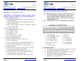
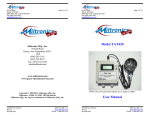
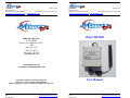
TM
TM
95 Krif Road
Page 12 of 12
Keene, NH 03431
(800) 283-1141 or (800) 828-9089
Fax: (603) 352-4444 or (603-352-1036)
[email protected] or [email protected]
95 Krif Road
Page 1 of 12
Keene, NH 03431
(800) 283-1141 or (800) 828-9089
Fax: (603) 352-4444 or (603-352-1036)
[email protected] or [email protected]
Model THT500
Miltronics Mfg., Inc.
95 Krif Road
Keene, New Hampshire 03431
USA
(800) 283-1141
(603) 352-0187
Fax: (603) 352-1036
[email protected]
www.miltronics.com
www.pacer-instruments-usa.com
User Manual
Copyright © 2009-2013, Miltronics Mfg., Inc.
Miltronics, AT400, TAT420, THT500 and the
Miltronics Mfg., Inc. logo are trademarks of Miltronics Mfg., Inc.
THT500 User Manual
Rev 1.2
06-Sept-2013
Miltronics Mfg. Svcs., Inc.
www.pacer-instruments-usa.com
www.miltronics.com
THT500 User Manual
Rev 1.2
06-Sept-2013
Miltronics Mfg. Svcs., Inc.
www.pacer-instruments-usa.com
www.miltronics.com
TM
TM
95 Krif Road
Page 2 of 12
Keene, NH 03431
(800) 283-1141 or (800) 828-9089
Fax: (603) 352-4444 or (603-352-1036)
[email protected] or [email protected]
95 Krif Road
Page 11 of 12
Keene, NH 03431
(800) 283-1141 or (800) 828-9089
Fax: (603) 352-4444 or (603-352-1036)
[email protected] or [email protected]
Notes:
Warranty
This product is fully warranted against defective materials
and/or workmanship for a period of one year after purchase,
provided it was not improperly used. For your protection,
please use this product as soon as possible. If returned, it must
be securely wrapped, sent prepaid and insured to:
Miltronics Mfg., Inc.
95 Krif Road
Keene, NH 03431
PH: 603-352-3333
FX: 603-352-4444
Please include a note with name, address, telephone number
and description of the problem. Although we provide
assistance on Pacer Instruments & Miltronics products both
personally and through our literature, it is still the total
responsibility of the customer to determine the suitability of the
product for use in their application.
This manual is provided by Miltronics Mfg., Inc. without any
kind of warranty. Precautions have been taken in accurately
preparing this manual; however, we neither assume
responsibility for any omissions or errors that may appear nor
assume liability for any damages that result from the use of the
products in accordance with the information contained in the
manual.
THT500 User Manual
Rev 1.2
06-Sept-2013
Miltronics Mfg. Svcs., Inc.
www.pacer-instruments-usa.com
www.miltronics.com
THT500 User Manual
Rev 1.2
06-Sept-2013
Miltronics Mfg. Svcs., Inc.
www.pacer-instruments-usa.com
www.miltronics.com
TM
TM
95 Krif Road
Page 10 of 12
Keene, NH 03431
(800) 283-1141 or (800) 828-9089
Fax: (603) 352-4444 or (603-352-1036)
[email protected] or [email protected]
95 Krif Road
Page 3 of 12
Keene, NH 03431
(800) 283-1141 or (800) 828-9089
Fax: (603) 352-4444 or (603-352-1036)
[email protected] or [email protected]
Notes:
INTRODUCTION
The THT500 humidity-temperature transmitters supply accurate
humidity and temperature (THT500) data from a room or process
air source on a continuous basis to a computer, chart recorder,
printer, meter or control circuit.
The AT400 and TAT420 air velocity transmitters supply accurate
air velocity and (TAT420) temperature data from a building or
process airflow on a continuous basis to a computer, chart
recorder, printer, and meter or control circuit.
Every instrument has terminals for both DC and AC power, and
0-1V, 0-5V and 4-20mA outputs. The outputs are concurrent and
can accept multiple wires (depending on the gauge used).
The humidity or humidity-temperature probe can be mounted on
the instrument enclosure or at a remote location; that choice must
be made at the time of purchase. The probe can be fitted with a
optional sintered-metal filter for dusty or harsh environments.
THT500 User Manual
Rev 1.2
06-Sept-2013
Miltronics Mfg. Svcs., Inc.
www.pacer-instruments-usa.com
www.miltronics.com
THT500 User Manual
Rev 1.2
06-Sept-2013
Miltronics Mfg. Svcs., Inc.
www.pacer-instruments-usa.com
www.miltronics.com
TM
TM
95 Krif Road
Page 4 of 12
Keene, NH 03431
(800) 283-1141 or (800) 828-9089
Fax: (603) 352-4444 or (603-352-1036)
[email protected] or [email protected]
95 Krif Road
Page 9 of 12
Keene, NH 03431
(800) 283-1141 or (800) 828-9089
Fax: (603) 352-4444 or (603-352-1036)
[email protected] or [email protected]
SPECIFICATIONS
Sensors:
Humidity sensor:
Capacitive (Thin Film)
Temperature:
PT100 RTD
Range:
Relative Humidity:
5% to 95% RH
Temperature:
-4˚ to 176˚F (-20˚ to 80˚C)
Accuracy:
Relative Humidity:
±2% RH
Temperature:
±0.5˚C
Resolution (optional display):
Relative Humidity:
0.1%RH
Temperature:
0.1˚F or ˚C
Response Time:
Relative Humidity:
90% of final value in 15 sec.
Temperature:
Approximately 60 seconds
Analog Outputs (separate and concurrent):
Relative Humidity:
0-1V, 0-5V and 4-20mA represent 0-100%RH
Temperature:
0-1V, 0-5V and 4-20mA represent -4 to 176˚F (-20 to 80˚C)
Operating Range:
-4˚ to 176˚F (-20˚ to 80˚C)
Power Supply:
120 or 220VAC, 50-60Hz, also
10-30 VDC
Input Current (with all options):
10-30VDC:
38mA
110VAC:
18mA
220VAC:
9mA
Output Impedance (0-1V and 0-5V outputs):
1KΩ
Enclosure:
ABS plastic, NEMA Class 4
Dimensions:
Housing:
Probe:
Weight:
Options:
Sintered-metal filter:
THT500 User Manual
Rev 1.2
06-Sept-2013
_____________________________
1
In order to insure the proper calibration, all custom-length cables
for the THT500 must be ordered at the time the transmitter is
purchased; or the unit must be returned for calibration.
2
The maximum length for probe cables is 150 ft.; please consult
manufacturer if longer cable is required.
3
Cable grips will seal on round cables from 2.5 to 6.5mm diameter.
For wire bundles, if you wish to insure water tightness, use RTV
silicon or other sealant safe for electronics at end of cable grip.
Notes:
4.8” x 4.8” x 2.2”
4.5” x 1” diameter
18 ounces
Harsh environments
Miltronics Mfg. Svcs., Inc.
www.pacer-instruments-usa.com
www.miltronics.com
THT500 User Manual
Rev 1.2
06-Sept-2013
Miltronics Mfg. Svcs., Inc.
www.pacer-instruments-usa.com
www.miltronics.com
TM
TM
95 Krif Road
Page 8 of 12
Keene, NH 03431
(800) 283-1141 or (800) 828-9089
Fax: (603) 352-4444 or (603-352-1036)
[email protected] or [email protected]
95 Krif Road
Page 5 of 12
Keene, NH 03431
(800) 283-1141 or (800) 828-9089
Fax: (603) 352-4444 or (603-352-1036)
[email protected] or [email protected]
INSTALLATION AND SETUP FOR THT500
APPENDIX A – No Longer Available
APPENDIX B – Collecting data by means of resident “HyperTerminal” program on Win 95, 98, NT4, and Win 2000 PC’s
A. Set up Communication Port.
1) Find and open “HyperTerminal” under “Accessories” and
“Communications”
2) Type a name like “Humidity Transmitter” and select an
icon, then click “OK”
3) In the “Connect using:” box, select a COM port - probably
“COM 1”. Click “OK”
B. Set up “COM 1 Properties”
1) Set “Bits per second:” to “1200”
2) Set “Data bits:” to “8”
3) Set “Parity:” to “None”
4) Set “Stop bits:” to “1”
5) Set “Flow control:” to “None”
6) Click “OK”, the select “Save”
C. Connect cable and transfer data
1) Connect the RS-232 cable to “COM 1” port
2) Power up transmitter
3) Select “Call” from “Call” menu. Data will fill window
4) To stop, select “Disconnect” from “Call” menu
5) To save data, select “Save As…” and give file a name
D. To transfer to Excel
1) Select data file from C5 above and open with “Notepad”
2) Select data to be transferred and “Copy”
3) Open a new blank Excel worksheet, select “Paste”
4) Select entire Column “A”. Under “Data” menu, select
“Text to columns…” and click “Next”
5) Follow directions to separate data, then click “Finish”
THT500 User Manual
Rev 1.2
06-Sept-2013
Miltronics Mfg. Svcs., Inc.
www.pacer-instruments-usa.com
www.miltronics.com
Note: Make all connections with Power Off. Remove cover to
attach Transmitter to mounting area and to attach
power and signal cables. Attach in location free of
physical dangers such as excessive heat or continuous
condensing moisture.3
Note: Terminals 13-15 are not installed on any transmitter.
TERMINAL CONNECTIONS
1.
2.
3.
4.
5.
6.
7.
8.
4-20 mA temp
0-1 Volt temp THT500
0-5 Volt temp
4-20 mA air velocity
0-5 Volt air velocity
0-1 Volt air velocity
Ground
V+ (10-30 VDC)
9. 220 VAC
10. 110 VAC
11. 220/110 VAC
12. No Connection
13. No Connection
14. No Connection
15. No Connection
POWER HOOKUP*
1a) If using 110VAC power, hook white (neutral) wire into slot
10. Then hook black (hot) wire into slot 11.
1b) If using 220VAC power, hook either hot wire into slot 11.
Then hook the other hot wire into slot 9.
1c) If using 10-30VDC, first hook ground wire into slot 7.
Then hook V+ wire into slot 8.
THT500 User Manual
Rev 1.2
06-Sept-2013
Miltronics Mfg. Svcs., Inc.
www.pacer-instruments-usa.com
www.miltronics.com
TM
TM
95 Krif Road
Page 6 of 12
Keene, NH 03431
(800) 283-1141 or (800) 828-9089
Fax: (603) 352-4444 or (603-352-1036)
[email protected] or [email protected]
%RH OUTPUT*
2a) If you want 0-1V FS, hook output ground reference to slot
7. Then hook %RH output wire to slot 6.
2b) If you want 0-5V FS, hook output ground reference to slot
7. Then hook %RH output wire to slot 5.
2c) If you want 4-20mA FS, hook output ground reference to
slot 7. Then hook %RH wire to slot 4.
95 Krif Road
Page 7 of 12
Keene, NH 03431
(800) 283-1141 or (800) 828-9089
Fax: (603) 352-4444 or (603-352-1036)
[email protected] or [email protected]
Diagram 1: Location and Polarity of Connectors and
Switches.
3.515”
8.93 cm
TEMPERATURE OUTPUT*
3a) If you want 0-1V FS, hook output ground reference to slot
7. Then hook temperature output wire to slot 3.
3b) If you want 0-5V FS, hook output ground reference to slot
7. Then hook temperature output wire to slot 2.
3c) If you want 4-20mA FS, hook output ground reference to
slot 7. Then hook temperature output wire to slot 1.
MOUNTING THE PROBE
Mount at location where measurements are to be made. Do not
change the length of the cable supplied at purchase, as doing so
will change the calibration. Protect the probe with a sinteredmetal filter (optional) if dust or spray is present.
Temperature
and humidity
2 3 4 Connections
Display
Connector
4.330”
11 cm
1
METRIC OR ENGLISH UNITS
Shown on the diagram but no longer available
REPLACING COVER
Use care not to damage the seal; if the cover has a display, use
proper polarity when reinstalling connectors (see Diagram 1).
DISPLAY SWITCH
Shown on the diagram but no longer available
*NOTE: Be sure to tighten screws above slots when finished.
THT500 User Manual
Rev 1.2
06-Sept-2013
Miltronics Mfg. Svcs., Inc.
www.pacer-instruments-usa.com
www.miltronics.com
5
Metric or
English
Units
Switch
THT500 User Manual
Rev 1.2
06-Sept-2013
Front cover
Switch
Connector
Note: Processor, switch and other
items on left of board are present
only when RS-232 and/or display
options are present.
Miltronics Mfg. Svcs., Inc.
www.pacer-instruments-usa.com
www.miltronics.com