1
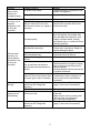
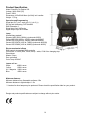
City Painter 250
ORDERCODE 40902
Congratulations!
You have bought a great, innovative product from Showtec.
The Showtec City Painter 250 brings excitement to any venue. Whether you want simple plug-&-play action
or a sophisticated DMX show, this product provides the effect you need.
You can rely on Showtec, for more excellent lighting products.
We design and manufacture professional light equipment for the entertainment industry.
New products are being launched regularly. We work hard to keep you, our customer, satisfied.
For more information: [email protected]
You can get some of the best quality, best priced products on the market from Showtec.
So next time, turn to Showtec for more great lighting equipment.
Always get the best -- with Showtec !
Thank you!
Showtec
Showtec City Painter 250™ Product Guide
Warning..…...................................................................................…………………………………………..
Safety-instructions………………………………………………………………………………………….….
Operating Determinations…………………………………………………………………………………….
2
2
3
Description..…..............................................................................……….…………………………………
Features and Overview ………………………………...….……………….………….………………….….
Backside…………………………………………………...…...….……………….…………………...….….
5
5
6
Installation...............................................................................…...…………………………………….…..
Installing the Lamp ........................................................………………………………………..…………
7
7
Set Up and Operation.....................................................................……..……………………………….…
One City Painter .........................................................................…………………………………………
Multiple City Painters…........................................................................…………………………………..
8
8
8
Line Board...............................................................................…...…………………………………….……
LUX Chart….............................................................................…...…………………………………….……
9
9
DMX-Protocol…...................................................……………………………………………………………..
Control Mode........................................………………………………………………………………………
DMX 512 Mode....................................………………………………………………………………………
DMX Addressing...................................………………………………………………………………………
DMX Channels...................................…………………………………………………………………..……
DMX Dip Switch Setting...................................…………………………………………………………..…
“2P” Function Mode switches and Address Dip switches............…………………………………………
Stand – alone mode...................................………………………………………………………………….
Master/Slave mode...................................…………………………………………………………………..
Stand – alone Colors.................................………………………………………………………………….
10
10
10
10
11
12
13
13
13
14
Maintenance...................................................................................………..………….…….………………
Changing the Lamp........................................................................…………………….…………………
Replacing the Fuse........................................................................…………………….…………………
15
15
15
Troubleshooting............................................................................………………….………………….…..
No Light, No Movement - All Products............................................………………….…………………..
No Response to DMX ....................................................................………………….…………………...
16
16
16
Product Specifications.................................................................……………….…….…………………...
18
1
WARNING
CAUTION!
Keep this device away from rain and moisture!
Unplug mains lead before opening the housing!
FOR YOUR OWN SAFETY, PLEASE READ THIS USER MANUAL CAREFULLY
BEFORE YOUR INITIAL START-UP!
SAFETY INSTRUCTIONS
Every person involved with the installation, operation and maintenance of this device has to:
be qualified
follow the instructions of this manual
CAUTION! Be careful with your operations.
With a dangerous voltage you can suffer
a dangerous electric shock when touching the wires!
Before your initial start-up, please make sure that there is no damage caused by transportation. Should
there be any, consult your dealer and do not use the device.
To maintain perfect condition and to ensure a safe operation, it is absolutely necessary for the user to follow
the safety instructions and warning notes written in this manual.
Please consider that damages caused by manual modifications to the device are not subject to warranty.
This device contains no user-serviceable parts. Refer servicing to qualified technicians only.
IMPORTANT:
The manufacturer will not accept liability for any resulting damages caused by the non-observance of
this manual or any unauthorized modification to the device.
•
•
•
•
•
•
•
•
•
•
•
•
•
•
•
Never let the power-cord come into contact with other cables! Handle the power-cord and all
connections with the mains with particular caution!
Never remove warning or informative labels from the unit.
Never use anything to cover the ground contact.
Never run the device without lamp!
Never ignite the lamp if the objective-lens or any housing-cover is open, as discharge lamps may
expose and emit a high ultraviolet radiation, which may cause burns.
Never lift the fixture by holding it at the projector-head, as the mechanics may be damaged. Always
hold the fixture at the transport handles.
Never look directly into the light source.
Never leave any cables lying around.
Never unscrew the screws of the rotating gobo, as the ball bearing will otherwise be opened.
Do not insert objects into air vents.
Do not connect this device to a dimmerpack.
Do not switch the device on and off in short intervals, as this would reduce the lamp’s life.
If the lamp has been turned OFF, let the lamp cool down for 15 minutes, before turning the lamp ON
again.
Do not touch the device’s housing bare-handed during its operation (housing becomes very hot).
Do not shake the device. Avoid brute force when installing or operating the device.
2
•
•
•
•
•
•
•
•
•
•
•
•
•
•
•
•
•
•
•
•
•
•
•
Only use device indoor, avoid contact with water or other liquids.
Only operate the fixture after having checked that the housing is firmly closed and all screws are
tightly fastened.
Only operate the device after having familiarized with its functions.
Avoid flames and do not put close to flammable liquids or gases.
Always replace the lamp, when it is damaged or deformed due to the heat.
Always keep case closed while operating.
Always allow free air space of at least 50 cm around the unit for ventilation.
Always disconnect power from the mains, when device is not used, before cleaning or when
replacing lamp! Only handle the power-cord by the plug. Never pull out the plug by tugging the
power-cord.
Make sure that the device is not exposed to extreme heat, moisture or dust.
Make sure that the available voltage is not higher than stated on the rear panel.
Make sure that the power-cord is never crimped or damaged. Check the device and the power-cord
from time to time.
If the lens is obviously damaged, it has to be replaced. So that its functions are not impaired, due to
cracks or deep scratches.
If device is dropped or struck, disconnect mains power supply immediately. Have a qualified
engineer inspect for safety before operating.
If the device has been exposed to drastic temperature fluctuation (e.g. after transportation), do not
switch it on immediately. The arising condensation water might damage your device. Leave the
device switched off until it has reached room temperature.
If your Showtec device fails to work properly, discontinue use immediately. Pack the unit securely
(preferably in the original packing material), and return it to your Showtec dealer for service.
For adult use only. City Painter must be installed out of the reach of children. Never leave the unit
running unattended.
For replacement use lamps and fuses of same type and rating only.
Allow time to cool down, before replacing lamp.
The user is responsible for correct positioning and operating of the Image Spot. The manufacturer
will not accept liability for damages caused by the misuse or incorrect installation of this device.
This device falls under protection class I. Therefore it is essential to connect the yellow/green
conductor to earth.
During the initial start-up some smoke or smell may arise. This is a normal process and does not
necessarily mean that the device is defective.
Repairs, servicing and electric connection must be carried out by a qualified technician.
WARRANTY: Till one year after date of purchase.
CAUTION ! EYEDAMAGES !.
Avoid looking directly into the light source.
(meant especially for epileptics) !
OPERATING DETERMINATIONS
This device is not designed for permanent operation. Consistent operation breaks will ensure that the device
will serve you for a long time without defects.
The minimum distance between light-output and the illuminated surface must be more than 1.5 meter.
The maximum ambient temperature ta = 45°C must never be exceeded.
The relative humidity must not exceed 50 % with an ambient temperature of 45° C.
If this device is operated in any other way, than the one described in this manual, the product may suffer
damages and the warranty becomes void.
3
Any other operation may lead to dangers like short-circuit, burns, electric shock, lamp explosion, crash etc.
You endanger your own safety and the safety of others!
Improper installation can cause serious damage to people and property !
Connection with the mains
Connect the device to the mains with the power-plug.
Always pay attention, that the right color cable is connected to the right place.
Cable
Pin
International
BROWN
FASE
L
BLUE
NUL
N
YELLOW/GREEN
EARTH
Make sure that the device is always connected properly to the earth!
4
Description of the device
Features
The Showtec City Painter 250 is a colourchanger with high output and great effects.
• DMX-control via standard DMX-controller
• 6 DMX-control channels required
• IP-65 Protection degree
• Stand-alone control or Master –Slave control
• Dimmer
• Color Temp 8500 Kº
• Lamp MSD 250
Note: If the lamp has been turned OFF, let the lamp cool down for 15 minutes, before turning the lamp ON
again.
Overview
1
2
Fig. 1
1) Lens
2) Adjustment Screw for inclination angle
5
Backside
Fig. 2
3 4
5 6
3) Power Output
4) Power Input
5) DMX signal connector (IN)
6) DMX signal connector (OUT)
Lumen at 2 m.:
White:
14000 Lumen
Yellow:
8500 Lumen
UV / Magenta: 2000 Lumen
Blue:
4850 Lumen
6
Installation
Installing the Lamp
The Showtec City Painter 250 uses the MSD 250 (ordercode 80920P / 80920O / 80933O / 82603 / 80935)
reflectorbulb as manufactured by all popular manufacturers. Use only the appropriate lamp for your unit.
Note that, product versions that use other lamps, may be offered in the future. Check your product
specification label for information.
Always disconnect from electric mains power supply before changing lamps.
The lamp has to be replaced when it is damaged or deformed due to the heat.
Do not install lamps with a higher wattage! Lamps with a higher wattage generate temperatures the
device was not designed for.
Damages caused by non-observance are not subject to warranty.
Procedure :
1. Loosen the 4 screws on the aluminum housing. Gently remove the metal housing.
2. Draw the mirrors (total of 6 mirrors in 3 layers) to the two sides carefully, and then you can see the lamp,
use a screwdriver to tweak the 2 screws which fixed in the glisten cup and take it out vertically.
3. Take out the old lamp vertically.
4. Read lamp instructions. Do not touch the lamp bulb glass. (See Figure 3 and 4.)
Oil on hands shortens the lamp life. (If you touch the bulb glass, wipe off the glass with a clean, lint-free
towel and rubbing alcohol.).
5. Insert the lamp pins into the small holes in the lamp socket. Put the glisten cup back and fasten the
screws snugly.
6. Put the metal housing back and fasten the screws snugly.
1
2
Fig. 3
Fig. 4
7
Set Up and Operation
Follow the directions below, as they pertain to your preferred operation mode.
Before plugging the unit in, always make sure that the power supply matches the product specification
voltage. Do not attempt to operate a 120V specification product on 230V power, or vice versa.
One City Painter
1. Leave at least 1 meter on all sides for air circulation.
2. Plug one end of the electric mains power cord into the IEC socket on the unit.
Then plug the other end of the cord into a proper electric power supply socket.
Multiple City painters
1. Leave at least 1 meter on all sides for air circulation.
2. Use a 3-p XLR cable to connect the City Painters and other devices.
The pins:
1.
2.
3.
Earth
Signal Signal +
3. Link the units as shown in (figure 5), Connect a DMX signal cable from the first unit's DMX "out" socket to
the second unit's "in" socket. Repeat this process to link the second, third, and fourth units.
4. Supply electric power: Plug electric mains power cords into each unit's IEC socket, then plug the other
end of the mains power cord into proper electric power supply sockets, starting with the first unit. Do not
supply power before the whole system is set up and connected properly.
Note: It’s necessary to insert a XLR termination plug (with 120 Ohm) in the last fixture in order to ensure
proper transmission on the DMX data link.
Multiple City Painters Set Up
DMX-Set up
Master/Slave Set up
Fig. 5
Note : Link all cables before connecting electric power
8
Line Board
LUX Chart
9
DMX Protocol
The City Painter 250 can be operated with a controller in control mode or without the controller in standalone mode.
Control Mode
DMX 512 Mode
When you want to use DMX mode set the “2P” dip switch 1 to “OFF” and 2 to “OFF”, as below:
DMX Addressing
The control panel on the front side of the base allows you to assign the DMX fixture address, which is the
first channel from which the City Painter will respond to the controller.
Please note when you use the controller, the unit has 6 channels.
When using multiple City Painters, make sure you set the DMX addresses right.
Therefore, the DMX address of the first City Painter should be 1(001); the DMX address of the second City
Painter should be 1+6=7 (007); the DMX address of the third City Painter should be 7+6=13(013), the DMX
address of the fourth City Painter should be 13+6=19(019), etc.
Unit No.
Address
Unit 1
1
Unit 2
7
Unit 3
13
Unit 4
19
Binary
Dip Switch Setting
Please, be sure that you don’t have any overlapping channels in order to control each City Painter correctly.
If two or more City Painters are addressed similarly, they will work similarly.
For address settings, please refer to the instructions under ”DMX 512 Mode”.
Controlling:
After having addressed all City Painter fixtures, you may now start operating these via your lighting
controller.
Note: After switching on, and switching both “2P” Dip switches to OFF, the City Painter will work with DMX
512 data.
If the device doesn’t work with DMX, the problem may be:
- The XLR cable from the controller is not connected with the input of the City Painter.
- The controller is switched off or defective, the cable or connector is detective, or the signal wires are
swapped in the input connector.
Note: It’s necessary to insert a XLR termination plug (with 120 Ohm) in the last fixture in order to ensure
proper transmission on the DMX data link.
10
DMX Channels
Channel 1 – Speed
0-255
From slow to fast to control the changing speed of the three
colors
Channel 2 – Yellow
0-255
Change the color from bright to dark Yellow.
Channel 3 – Aubergine
0-255
Change the color from bright to dark Aubergine.
Channel 4 – Blue
0-255
Change the color from bright to dark Blue.
Channel 5 – Macro Colourwheel + Rainbow
Linear color change following the movement of the slider.
0-25
26-50
51-76
77-102
103-128
129-154
155-180
181-206
207-232
233-255
Open / white
Yellow
Aubergine
Blue
Red
Green
Deep Blue
AubergineDeep BlueBlueGreenWhiteYellowRed
(approx 30 sec/time)
AubergineDeep BlueBlueGreenWhiteYellowRed
(approx 20 sec/time)
AubergineDeep BlueBlueGreenWhiteYellowRed
(approx 10 sec/time)
Channel 6 – Stop Macrowheel
0-255
Keeping the current color
11
DMX Dip Switch Setting
12
“2P” Function Mode switches and Address Dip switches
Stand-alone Mode
The fixtures on a data-link are not connected to the controller, but can execute pre-set programs, which can
be different for every fixture. To set the program to be played, see the page 14.
When you want to use stand-alone mode set the “2P” dip switch 1 to “ON” and 2 to “OFF”, as below:
Stand-alone operation” can be applied to a single fixture (the fixture may be set to the master/slave mode
or controller mode) or to multiple fixture operating synchronously.
Master / Slave Mode
For synchronous operation of multiple fixtures the fixtures must all be connected on a data-link and one of
them is set as a master (master mode DIP switch 1 ON) and the rest as slaves (slave mode DIP switch 1
OFF). The DMX address of all the slaves are assigned and on that particular slave address only one fixture
can be connected.
Master
Slave
If the master fixture resets or runs a test (program), all slaves will execute these acts too.
Note: Disconnect the fixtures from the DMX controller before master/slave operating, otherwise data
collisions can occur and the fixtures will not work properly!
It’s necessary to insert the XLR termination plug (with 120 Ohm) into the input of the master fixture and into
the output of the last slave fixture in the data-link, in order to ensure proper transmission on the data link.
From the master’s control panel it is possible to control any slave in a master/slave chain.
13
Stand Alone - Colors
Address
codes
Code 0
Code 1
Code 2
Code 3
Code 4
Code 5
Code 6
Code 7
Code 8
Code 9
Code 10
Code 11
Code 12
Code 13
Code 14
Code 15
Code 16
Code 17
Code 18
Code 19
Code 20
Code 21
Code 22
Code 23
Code 24
Code 25
Code 26
Code 27
Code 28
Function
Open / white
Blue
Light Blue
Rose Red
Yellow
Deep Orchid
Straw Yellow
Green
Red
Light Yellow
Aubergine
AubergineDeep BlueBlueGreenWhiteYellowRed (approx 30 sec/time)
AubergineDeep BlueBlueGreenWhiteYellowRed (approx 20 sec/time)
AubergineDeep BlueBlueGreenWhiteYellowRed (approx 10 sec/time)
AubergineDeep BlueBlueGreenYellowRed (approx 30 sec/time)
AubergineDeep BlueBlueGreenYellowRed (approx 20 sec/time)
AubergineDeep BlueBlueGreenYellowRed (approx 10 sec/time)
AubergineBlueYellow (approx 30 sec/time)
AubergineBlueYellow (approx 20 sec/time)
AubergineBlueYellow (approx 10 sec/time)
AubergineBlueWhiteYellow (approx 30 sec/time)
AubergineBlueWhiteYellow (approx 20 sec/time)
AubergineBlueWhiteYellow (approx 10 sec/time)
AubergineYellowRed (approx 30 sec/time)
AubergineWhiteYellowRed (approx 30 sec/time)
GreenBlueYellow (approx 30 sec/time)
GreenBlueWhiteYellow (approx 30 sec/time)
AubergineDeep BlueBlue (approx 30 sec/time)
AubergineDeep BlueBlueWhite (approx 30 sec/time)
14
Maintenance
The operator has to make sure that safety-relating and machine-technical installations are to be inspected
by an expert after every four years in the course of an acceptance test.
The operator has to make sure that safety-relating and machine-technical installations are to be inspected
by a skilled person once a year.
The following points have to be considered during the inspection:
1. All screws used for installing the device or parts of the device have to be tightly connected and must
not be corroded.
2. There may not be any deformations on housings, fixations and installation spots.
3. Mechanically moving parts like axles, eyes and others may not show any traces of wearing.
4. The electric power supply cables must not show any damages or material fatigue.
The Showtec City Painter 250 requires almost no maintenance. However, you should keep the unit clean.
Otherwise, the fixture’s light-output will be significantly reduced. Disconnect the mains power supply, and
then wipe the cover with a damp cloth. Do not immerse in liquid. Wipe lens clean with glass cleaner and a
soft cloth. Do not use alcohol or solvents.
The cooling-fans, colour-filters, and the internal lenses should be cleaned monthly with a soft brush.
Please clean internal components once a year with a light brush and vacuum cleaner.
Keep connections clean. Disconnect electric power, and then wipe the DMX and audio connections with a
damp cloth. Make sure connections are thoroughly dry before linking equipment or supplying electric power.
Changing the Lamp
1. Loosen the 4 screws on the aluminum housing. Gently remove the metal housing.
2. Draw the mirrors (total of 6 mirrors in 3 layers) to the two sides carefully, and then you can see the lamp,
use a screwdriver to tweak the 2 screws which fixed in the glisten cup and take it out vertically.
3. Take out the old lamp vertically.
4. Follow directions for installing a new lamp, page 7.
Replacing a Fuse
Power surges, short-circuit or inappropriate electrical power supply may cause a fuse to burn out. If the fuse
burns out, the product will not function whatsoever. If this happens, follow the directions below to do so.
1. Unplug the unit from electric power source.
2. Insert a flat-head screwdriver into a slot in the fuse cover. Gently pry up the fuse cover. The fuse will
come out.
3. Remove the used fuse. If brown or unclear, it is burned out.
4. Insert the replacement fuse into the holder where the old fuse was. Reinsert the fuse cover. Be sure to
use a fuse of the same type and specification. See the product specification label for details.
15
Troubleshooting
No Light
This troubleshooting guide is meant to help solve simple problems. If a problem occurs, carry out the steps
below in sequence until a solution is found. Once the unit operates properly, do not carry out following
steps.
If the light effect does not operate properly, refer servicing to a technician.
Response: Suspect three potential problem areas: the power supply, the lamp, the fuse.
1. Power supply. Check that the unit is plugged into an appropriate power supply.
2. The lamp. Replace the old lamp with a new one with the same specifications. See page 7 for replacing
lamps.
3. The fuse. Replace the fuse. See page 15 for replacing the fuse.
No Response to DMX
Response: Suspect the DMX cable or connectors, a controller malfunction, a light effect DMX card
malfunction.
1. Check the DMX cable: Unplug the unit; change the DMX cable; then reconnect to electrical power. Try
your DMX control again.
2. Determine whether the controller or light effect is at fault. Does the controller operate properly with other
DMX products ? If not, take the controller in for repair. If so, take the DMX cable and the light effect to a
qualified technician.
See next page for more problem solving.
16
Problem
One or more
fixtures are
completely dead.
Fixtures reset
correctly, but all
respond
erratically or not
at all to the
controller.
Probable cause(s)
No power to the fixture
Remedy
·Check that power is switched on and
cables are plugged in.
Primary fuse blown.
·Replace fuse.
The controller is not connected.
3-pin XLR Out of the controller
does not match XLR Out of the
first fixture on the link (i.e. signal is
reversed).
·Connect controller.
·Install a phase reversing cable
between the controller and the first
fixture on the link.
·Check data quality. If much lower
than 100 percent, the problem may
be a bad data link connection, poor
quality or broken cables, missing
termination plug, or a defective fixture
disturbing the link.
Poor data quality
Bad data link connection
Fixtures reset
correctly, but
some respond
erratically or not
at all to the
controller.
Data link not terminated with 120
Ohm termination plug.
Incorrect addressing of the
fixtures.
One of the fixtures is defective
and disturbs data transmission on
the link.
3-pin XLR Out on the fixtures does
not match (pins 2 and 3 reversed).
No light
Lamp cuts out
intermittently.
The power supply settings do not
match local AC voltage and
frequency.
Lamp missing or blown
Fixture is too hot.
The power supply settings do not
match local AC voltage and
frequency.
17
·Inspect connections and cables.
Correct poor connections. Repair or
replace damaged cables.
·Insert termination plug in output jack
of the last fixture on the link.
·Check address setting.
·Bypass one fixture at a time until
normal operation is regained: unplug
both connectors and connect them
directly together.
·Have the defective fixture serviced by
a qualified technician.
·Install a phase-reversing cable
between the fixtures or swap pin 2
and 3 in the fixture, that behaves
erratically.
·Disconnect fixture. Check settings
(page 7) and correct if necessary.
·Disconnect fixture and replace lamp.
·Allow fixture to cool.
·Clean fan.
·Make sure air vents at control panel
and front lens are not blocked.
·Turn up the air conditioning.
·Disconnect fixture. Check settings
(page 7) and correct if necessary.
Product Specification
Model: Showtec City Painter 250
Voltage: 240V-50Hz (CE)
Power: 350W
Dimensions: 425x220x610mm (LxWxH) incl. handles
Weight: 17,5 kg
Operation and Programming
Signal pin OUT: pin 1 earth, pin 2 (-), pin 3 (+)
Set Up and Addressing: DIP Switches
DMX Channels: 6
Signal input 3-pin XLR male
Signal output 3-pin XLR female
Lamp
Allowed lamp models*:
Showtec NSD 250/2 (2000 hr) (ordercode 82603)
Philips MSD 250 (3000 hr; 6700K) ordercode 80920P
Osram HSD 250 (2000 hr; 6000K) ordercode 80926O
Osram HSD 250/78 (1000 hr; 7800K) (ordercode 80933O)
Osram HSD 250/80 (1000 hr; 8000K) (ordercode 80935)
Electro-mechanical effects
DMX-control via standard DMX-controller
Color effect: 3 Colors (Red, Yellow, Blue) + white, CYM Color changing step
Stand-alone
Master / Slave
Dmx-controlled
Color Temp: 8500 Kº
Lumen at 2 m.:
White:
14000 Lumen
Yellow:
8500 Lumen
UV / Magenta: 2000 Lumen
Blue:
4850 Lumen
Minimum distance:
Minimum distance from flammable surfaces: 0.5m
Minimum distance to lighted object: 1.5m
*: Versions for other lamps may be produced. Please check the specification label on your product.
Design and product specifications are subject to change without prior notice.
18
2006 Showtec.