1
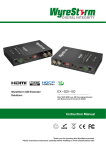
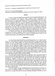
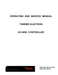
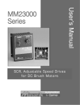
SCR, Adjustable Speed Drives
for DC Brush Motors
User’s Manual
GS23000C
Series
Contents
Safety Warnings
denotes an important safety tip or warning.
• This symbol
Please read these instructions carefully before performing
any of the procedures contained in this manual.
• DO NOT INSTALL, REMOVE, OR REWIRE THIS EQUIPMENT
WITH POWER APPLIED. Have a qualified electrical technician
install, adjust and service this equipment. Follow the National
Electrical Code and all other applicable electrical and safety codes,
including the provisions of the Occupational Safety and Health Act
(OSHA), when installing equipment.
• Reduce the chance of an electrical fire, shock, or explosion by
proper grounding, over-current protection, thermal protection, and
enclosure. Follow sound maintenance procedures.
It is possible for a drive to run at full speed as a result of
a component failure. Manufacturer strongly recommends
the installation of a master switch in the main power input to
stop the drive in an emergency.
Circuit potentials are at 115 VAC or 230 VAC above earth
ground. Avoid direct contact with the printed circuit board
or with circuit elements to prevent the risk of serious injury
or fatality. Use a non-metallic screwdriver for adjusting the
calibration trimpots. Use approved personal protective
equipment and insulated tools if working on this drive with
power applied.
2
Safety Warnings . . . . . . . . . . . . . . . . . . . . . . . . . . . . . . . . . . . . . . . . . . 2
Specifications . . . . . . . . . . . . . . . . . . . . . . . . . . . . . . . . . . . . . . . . . . . . 3
Dimension . . . . . . . . . . . . . . . . . . . . . . . . . . . . . . . . . . . . . . . . . . . . . . . 4
Installation . . . . . . . . . . . . . . . . . . . . . . . . . . . . . . . . . . . . . . . . . . . . . . . 5
Chassis drives . . . . . . . . . . . . . . . . . . . . . . . . . . . . . . . . . . . . . . . . . . . 6
Mounting . . . . . . . . . . . . . . . . . . . . . . . . . . . . . . . . . . . . . . . . . . . . . 5
Wiring . . . . . . . . . . . . . . . . . . . . . . . . . . . . . . . . . . . . . . . . . . . . . . . . 5
Shielding guidelines . . . . . . . . . . . . . . . . . . . . . . . . . . . . . . . . . . . . . 5
Heat sinking . . . . . . . . . . . . . . . . . . . . . . . . . . . . . . . . . . . . . . . . . . . 5
Speed adjust potentiometer . . . . . . . . . . . . . . . . . . . . . . . . . . . . . . . 5
Chassis drive connections . . . . . . . . . . . . . . . . . . . . . . . . . . . . . . . . 6
Power, fuse and motor connections . . . . . . . . . . . . . . . . . . . . . . . . . 6
Voltage follower . . . . . . . . . . . . . . . . . . . . . . . . . . . . . . . . . . . . . . . . 7
Cased drives . . . . . . . . . . . . . . . . . . . . . . . . . . . . . . . . . . . . . . . . . . . . 7
Mounting (NEMA 1 enclosures) . . . . . . . . . . . . . . . . . . . . . . . . . . . . 7
Heat sinking . . . . . . . . . . . . . . . . . . . . . . . . . . . . . . . . . . . . . . . . . . . 7
Line fusing . . . . . . . . . . . . . . . . . . . . . . . . . . . . . . . . . . . . . . . . . . . . 7
Connections . . . . . . . . . . . . . . . . . . . . . . . . . . . . . . . . . . . . . . . . . . . 7
Current limit LED (C models only) . . . . . . . . . . . . . . . . . . . . . . . . . . . . 8
Meter header block (cased C models only) . . . . . . . . . . . . . . . . . . . . . 8
Operation . . . . . . . . . . . . . . . . . . . . . . . . . . . . . . . . . . . . . . . . . . . . . . . . 8
Before applying power . . . . . . . . . . . . . . . . . . . . . . . . . . . . . . . . . . . . . 8
Voltage select switches . . . . . . . . . . . . . . . . . . . . . . . . . . . . . . . . . . . . 8
Input voltage select (SW501) . . . . . . . . . . . . . . . . . . . . . . . . . . . . . . 8
Armature voltage select (SW502) . . . . . . . . . . . . . . . . . . . . . . . . . . 8
Startup . . . . . . . . . . . . . . . . . . . . . . . . . . . . . . . . . . . . . . . . . . . . . . . . . 9
GS23001C . . . . . . . . . . . . . . . . . . . . . . . . . . . . . . . . . . . . . . . . . . . . 9
GS23101C . . . . . . . . . . . . . . . . . . . . . . . . . . . . . . . . . . . . . . . . . . . . 9
GS23201C . . . . . . . . . . . . . . . . . . . . . . . . . . . . . . . . . . . . . . . . . . . . 9
Starting and stopping methods . . . . . . . . . . . . . . . . . . . . . . . . . . . . . . 9
Line starting and line stopping . . . . . . . . . . . . . . . . . . . . . . . . . . . . . 9
Inhibit terminals . . . . . . . . . . . . . . . . . . . . . . . . . . . . . . . . . . . . . . . . 9
Decelerating to minimum speed . . . . . . . . . . . . . . . . . . . . . . . . . . 10
Dynamic braking . . . . . . . . . . . . . . . . . . . . . . . . . . . . . . . . . . . . . . 10
Calibration . . . . . . . . . . . . . . . . . . . . . . . . . . . . . . . . . . . . . . . . . . . . . . 11
MINIMUM SPEED (MIN SPD) . . . . . . . . . . . . . . . . . . . . . . . . . . . . . . 11
MAXIMUM SPEED (MAX SPD) . . . . . . . . . . . . . . . . . . . . . . . . . . . . . 11
TORQUE . . . . . . . . . . . . . . . . . . . . . . . . . . . . . . . . . . . . . . . . . . . . . . 11
IR COMPENSATION (IR COMP) . . . . . . . . . . . . . . . . . . . . . . . . . . . . 12
ACCELERATION (ACCEL) . . . . . . . . . . . . . . . . . . . . . . . . . . . . . . . . 12
DECELERATION (DECEL) . . . . . . . . . . . . . . . . . . . . . . . . . . . . . . . . 12
Application Notes . . . . . . . . . . . . . . . . . . . . . . . . . . . . . . . . . . . . . . . . 13
Multiple fixed speeds . . . . . . . . . . . . . . . . . . . . . . . . . . . . . . . . . . . . . 13
Adjustable speeds using potentiometers in series . . . . . . . . . . . . . . . 13
Independent adjustable speeds . . . . . . . . . . . . . . . . . . . . . . . . . . . . . 13
RUN/JOG switch . . . . . . . . . . . . . . . . . . . . . . . . . . . . . . . . . . . . . . . . 13
RUN/JOG switch option #1 . . . . . . . . . . . . . . . . . . . . . . . . . . . . . . 13
RUN/JOG switch option #2 . . . . . . . . . . . . . . . . . . . . . . . . . . . . . . 13
Leader-follower application . . . . . . . . . . . . . . . . . . . . . . . . . . . . . . . . 14
Single speed potentiometer control of multiple drives . . . . . . . . . . . . 14
Reversing . . . . . . . . . . . . . . . . . . . . . . . . . . . . . . . . . . . . . . . . . . . . . . 14
Reversing with a DIGI-LOK controller . . . . . . . . . . . . . . . . . . . . . . . . 14
Troubleshooting . . . . . . . . . . . . . . . . . . . . . . . . . . . . . . . . . . . . . . . . . 15
Before troubleshooting . . . . . . . . . . . . . . . . . . . . . . . . . . . . . . . . . . . . 15
CE Compliance . . . . . . . . . . . . . . . . . . . . . . . . . . . . . . . . . . . . . . . . . . 17
Line filters . . . . . . . . . . . . . . . . . . . . . . . . . . . . . . . . . . . . . . . . . . . . . . 17
Armature filters . . . . . . . . . . . . . . . . . . . . . . . . . . . . . . . . . . . . . . . . . . 17
GoldSpec™ User’s Manual
Illustrations
Figure 1.
Figure 3.
Figure 4.
Figure 8.
Figure 10.
Figure 11.
Figure 13.
Figure 14.
Figure 15.
Figure 16.
Figure 17.
Figure 18.
Figure 19.
Specifications
GS23001C. . . . . . . . . . . . . . . . . . . . . . . . . . . . . . . . . . . . . . . 4
GS23101C. . . . . . . . . . . . . . . . . . . . . . . . . . . . . . . . . . . . . . . 4
GS23201C. . . . . . . . . . . . . . . . . . . . . . . . . . . . . . . . . . . . . . . 4
Heat Sink Dimensions . . . . . . . . . . . . . . . . . . . . . . . . . . . . . . 4
Speed Adjust Potentiometer. . . . . . . . . . . . . . . . . . . . . . . . . . 5
Chassis Drive Connections . . . . . . . . . . . . . . . . . . . . . . . . . . 6
Voltage Follower Connections . . . . . . . . . . . . . . . . . . . . . . . . 7
Cased Drive Connections. . . . . . . . . . . . . . . . . . . . . . . . . . . . 8
Voltage Switches . . . . . . . . . . . . . . . . . . . . . . . . . . . . . . . . . . 8
INHIBIT Terminals . . . . . . . . . . . . . . . . . . . . . . . . . . . . . . . . . 9
Run/Decelerate to Minimum Speed Switch . . . . . . . . . . . . . 10
Dynamic Brake Connection . . . . . . . . . . . . . . . . . . . . . . . . . 10
Recommended Torque and IR COMP Settings . . . . . . . . . . 12
Figure 20. Multiple Fixed Speeds . . . . . . . . . . . . . . . . . . . . . . . . . . . . . 13
Figure 21. Adjustable Fixed Speeds Using Potentiometers
in Series. . . . . . . . . . . . . . . . . . . . . . . . . . . . . . . . . . . . . . . . 13
Figure 22. Independent Adjustable Speeds. . . . . . . . . . . . . . . . . . . . . . 13
Figure 23. RUN/JOG Switch Connection to Inhibit Plug (Option #1). . . 13
Figure 24. RUN/JOG Switch Connection to
Speed Adjust Potentiometer (Option #2) . . . . . . . . . . . . . . . 13
Figure 25. Leader-Follower Application. . . . . . . . . . . . . . . . . . . . . . . . . 14
Figure 26. Single Speed Potentiometer Control of Multiple Drives. . . . 14
Figure 27. Reversing Circuit Connection. . . . . . . . . . . . . . . . . . . . . . . . 14
Figure 28. Reversing with a GS600. . . . . . . . . . . . . . . . . . . . . . . . . . . . 14
FIgure 29. GS23000C Series Block Diagram . . . . . . . . . . . . . . . . . . . . 16
FIgure 30. GS23101C Terminal Block Connections . . . . . . . . . . . . . . . 16
FIgure 31. GS23201C Terminal Block Connections . . . . . . . . . . . . . . . 16
Model
Max.
Armature
Current
(Amps DC)
HP Range
Current with
115 VAC
Applied
HP Range
Current with 230
VAC Applied
Style
GS23001C †
5.0
1/8–1/2
1/4–1
Chassis
GS23101C ‡
NEMA 1
GS23201C ‡
NEMA 1
† Double maximum armature current and horsepower when drive is mounted on heat
sink part number gs223-0159.
‡ Double maximum armature current and horsepower when drive is mounted on heat sink
part number gs223-0174.
AC Line Voltage
115 VAC or 230 VAC ±10%, 50/60 Hz, single phase
Armature Voltage (115 VAC Input)
0–90 VDC
Armature Voltage (230 VAC Input)
0–180 VDC
Form Factor
50 VDC (F1 to L1); 100 VDC (F1 to F2)
Field Voltage (230 VAC Input)
100 VDC (F1 to L1); 200 VDC (F1 to F2)
Max. Field Current
0.5–11 seconds
0.5–22 seconds
Decel. Time Range:
for 0-90 VDC Armature Voltage
for 0–180 VDC Armature Voltage
coast to a stop–13 seconds
coast to a stop–25 seconds
Analog Input Voltage Range (signal must be isolated; S1 to S2):
for 0–90 VDC Armature Voltage
for 0–180 VDC Armature Voltage
0–1.4 VDC
0–2.8 VDC
Input Impedance (S1 to S2)
100K ohms
Load Regulation
1% base speed or better
Vibration0.5G max (0–50 Hz)0.1G max (>50 Hz)
Ambient Temp. Range (chassis drive)
Table 1. Recommended Line Fuse Sizes . . . . . . . . . . . . . . . . . . . . . . . . . 6
Table 2. Field Output Connections . . . . . . . . . . . . . . . . . . . . . . . . . . . . . . 6
Table 3. Field Output Connections . . . . . . . . . . . . . . . . . . . . . . . . . . . . . . 8
Table 4. Minimum Recommended Dynamic Brake Resistor Values. . . . 10
Table 6. Corcom ® Filters. . . . . . . . . . . . . . . . . . . . . . . . . . . . . . . . . . . . . 17
Table 7. GoldSpec™ Filters. . . . . . . . . . . . . . . . . . . . . . . . . . . . . . . . . . . 17
1 ADC
Accel. Time Range:
for 0–90 VDC Armature Voltage
for 0–180 VDC Armature Voltage
Safety Certification
Tables
1.37 at base speed
Field Voltage (115 VAC Input)
Ambient Temp. Range (cased drive)
GS23000C Series
UL Listed Equipment, file # E132235
UL Overload Protection
CSA Certified Component, file # LR41380
CE Certificate of Compliance
10°C–55°C
10°C–40°C
3
250-0091r8.qxp
1/24/2005
2:20 PM
Page 3
250-0091r8.qxp
1/24/2005
2:20 PM
Page 6
3
Dimensions
Dimensions
6
Dimensions
6.00 [125]
D502
A2
F2
V5
01
1.79
[45]
SCR502
C503
MO
D503
R502
L1
0.19 [5]
R501
D501
MOV502
SCR501
C
L
2.50
[64]
2.50
[64]
F1
C501
L2
3.58 [91]
IC502
MOV503
SW501
A1
1.75 [44]
115
230
8.00 [203]
SO502
+
METER
S2
C502
5.00
[127]
IC501
C504
90
S3
INHIBIT
CL
180
SW502
IL501
S1
0.74 [19]
0.64 [16]
ACCEL
DECEL
MAX SPD
MIN SPD
TORQUE
IR COMP
0.19 [5]
1.60 [41]
1.28 [33]
3.46 [88]
0.96 [24]
2.75
[70]
1.25 [32]
3.80 [97]
1.72
[44]
4.30 [109]
ALL DIMENSIONS IN INCHES (MILLIMETERS)
2.50
[64]
FOUR
MOUNTING
(5MILLIMETERS]
MILLIMETERS)WIDE
WIDE
FOUR
MOUNTINGSLOTS
SLOTS 0.19
0.19 INCHES
INCHES [5
ALL DIMENSIONS IN INCHES [MILLIMETERS]
Figure 1. GS23001C Dimensions
250-0091r8.qxp
250-0091r8.qxp
1/24/2005
2:20
Page Dimensions
5
Figure
1. MM23001
and PM
MM23011
TWO0.88
0.88 (22)
[22] KNOCKOUTS
TWO
KNOCKOUTS
1/24/2005
2:20 PM
Page 10
ALLDIMENSIONS
DIMENSIONS IN
IN INCHES
INCHES [MILLIMETERS]
ALL
(MILLIMETERS)
Figure 4. GS23201C Dimensions
Figure 4. MM23201 and MM23211 Dimensions
Dimensions
5
10
Dimensions
6.00 [125]
6.90 [175]
8.00
[203]
6.30 [160]
5.90 [150]
CL
1.79
[45]
2.50
[64]
2.50
[64]
C
5.00
[127]
A
D
B
E
3.46
[88]
MOUNTING
SLOTS0.19
0.19XX0.34
0.34[5(5X9)
MOUNTING SLOTS
X 9]
2.75
[70]
ALLDIMENSIONS
DIMENSIONS IN
IN INCHES
INCHES [MILLIMETERS]
ALL
(MILLIMETERS)
1.25 [32]
1.72
[44]
2.50
[64]
PART
NO. DIM DIM
PART
NO.
“A” “A”
DIMDIM
“B”“B”
DIM“C”
“C”
DIM
DIM“D”
“D”
DIM
223-0159
4.40 [112]
3.00 [76]
0.7 [18]
1.75 [44]
3.90 [100]
223-0174
7.78 [198]
6.00 [152]
0.89 [23]
6.00 [152]
5.35 [136]
GS223-0159
TWO
HOLES
TWO0.88
0.88 (22)
[22] CONDUIT
CONDUIT HOLES
ALL
(MILLIMETERS)
ALLDIMENSIONS
DIMENSIONS IN
IN INCHES
INCHES [MILLIMETERS]
GS223-0174
7.78 (198)
3.00 (76)
6.00 (152)
0.7 (18)
0.89 (23)
1.75 (44)
6.00 (152)
Heat
Heatsinks
sinkssold
soldseparately.
separately.
Figure 3. GS23101C Dimensions
Figure 8. HEAT SINK Dimensions
Figure 3. MM23101 and MM23111 Dimensions
4
4.40 (112)
Figure 8. Heat Sink Dimensions
GoldSpec™ User’s Manual
DIM “E”
DIM
“E”
3.90 (100)
5.35 (136)
Installation
Shielding guidelines
Warning
Warning
Do not install, rewire, or remove this control with input
power applied. Doing so may cause fire or serious injury.
Make sure you have read and understood the Safety
Warnings on page 2 before attempting installation.
Under no circumstances should power and logic leads be
bundled together. Induced voltage can cause unpredictable
behavior in any electronic device, including motor controls.
As a general rule, manufacturer recommends shielding of all
conductors.
Chassis drives
Mounting
If it is not practical to shield power conductors, manufacturer
recommends shielding all logic-level leads. If shielding of logic
leads is not practical, the user should twist all logic leads with
themselves to minimize induced noise.
• Drive components are sensitive to electrostatic fields. Avoid
contact with the circuit board directly. Hold drive by the chassis
only.
• Protect the drive from dirt, moisture, and accidental contact.
It may be necessary to earth ground the shielded cable. If noise is
produced by devices other than the drive, ground the shield at the
drive end. If noise is generated by a device on the drive, ground the
shield at the end away from the drive. Do not ground both ends of
the shield.
• Provide sufficient room for access to the terminal block and
calibration trimpots.
• Mount the drive away from other heat sources. Operate the drive
within the specified ambient operating temperature range.
• Prevent loose connections by avoiding excessive vibration of the
drive.
• Mount drive with its board in either a horizontal or vertical plane.
Six 0.19 inch (5 mm) wide slots in the chassis accept #8 pan head
screws. Fasten either the large base or the narrow flange of the
chassis to the subplate.
• The chassis must be earth grounded. To ground the chassis, use
a star washer beneath the head of at least one of the mounting
screws to penetrate the anodized chassis surface and to reach
bare metal.
If the drive continues to pick up noise after grounding the shield, it
may be necessary to add AC line filtering devices, or to mount the
drive in a less noisy environment.
Logic wires from other input devices, such as motion controllers
and PLL velocity controllers, must be separated from power lines in
250-0091r8.qxp
1/24/2005
2:20I/OPMon this
Page
16
the same manner
as the logic
drive.
Heat sinking
16
Model GS23001C requires require an additional heat sink when the
continuous armature current is above 5 ADC. Use GoldSpec™ part
Installation
number
GS223-0159. Use a thermally Sink Compound) between
the drive chassis and heat sink surface for optimum heat transfer.
Speed adjust potentiometer
Wiring
Warning
Do not install, remove, or rewire this equipment with power
applied. Failure to heed this warning may result in fire,
explosion, or serious injury.
Circuit potentials are at 115 or 230 VAC above ground. To
prevent the risk of injury or fatality, avoid direct contact with
the printed circuit board or with circuit elements.
Do not disconnect any of the motor leads from the drive
unless power is removed or the drive is disabled. Opening
any one motor lead may destroy the drive.
• Use 18-24 AWG wire for speed adjust potentiometer wiring.
Use 14–16 AWG wire for AC line (L1, L2) and motor (A1 and A2)
wiring.
Warning
Speed adjust potentiometer
Be sure that the potentiometer tabs do not make contact with
Warning
the potentiometer enclosure. Grounding the input will cause
Be sure
potentiometer tabs do not make contact
damage
tothat
the the
drive.
with the potentiometer enclosure. Grounding the input will
damage
to the
drive.
Mount cause
the speed
adjust
potentiometer
through a 0.38 in. (10 mm)
hole with the hardware provided (Figure 10). Install the circular
insulating
between
the panel and through
the 10K aohm
Mount
the disk
speed
adjust potentiometer
0.38speed
in. (10adjust
mm)
potentiometer.
hole with the hardware provided (Figure 10). Install the circular
insulating disk between the panel and the 10K ohm speed adjust
Twist the speed adjust potentiometer wire to avoid picking up
potentiometer.
unwanted
electrical
noise.
If speed adjust
potentiometer
Twist
the speed
adjust
potentiometer
wire to
avoid pickingwires
up are
longer
thanelectrical
18 in. (457
mm),
use shielded
cable. Keep speed
unwanted
noise.
If speed
adjust potentiometer
wires are
adjust potentiometer
wires
separate
from power
L2,adjust
A1,
longer
than 18 in. (457
mm),
use shielded
cable. leads
Keep (L1,
speed
A2).
potentiometer
wires separate from power leads (L1, L2, A1, A2).
MOUNT THROUGH A 0.38 IN. (10 MM) HOLE
CW
WIPER
W
NUT
STAR
WASHER
SPEED ADJUST
POTENTIOMETER
INSULATING DISK
PANEL
Figure 10. Speed Adjust Potentiometer
GS23000C Series
5
Installation (continued)
Chassis drive connections
Table 1. Recommended Line Fuse Sizes
Warning
90 VDC Motor
180 VDC
Max. DC Armature
AC Line Fuse
Do not connect this equipment with power applied.
Horsepower
Horsepower
Current (amps)
Size (amps)
1/20
1/10
0.5
1
Failure to heed this directive may result in fire or serious
injury.
1/15
1/8
0.8
1.5
1/8
1/4
1.5
3
1/6
1/3
1.7
3
1/4
1/2
2.5
5
1/3
3/4
3.5
8
1/2
1
5.0
10
3/4
1 1/2
7.5
15
1
2
10
15
Manufacturer strongly recommends the installation
of a master power switch in the voltage input line, as
shown in Figure 11 (page 6). The switch contacts should
be rated at a minimum of 200% of motor nameplate
current and 250 volts.
Power, fuse and motor connections
Connect the power input leads, an external line fuse and a DC motor
to TB501 on the drive’s printed circuit board (PCB) as shown in
Figure 11, page 6.
Field output connections
Motor
Warning
GoldSpec™ drives supply motor armature voltage from A1 and A2
terminals. It is assumed throughout this manual that, when A1 is
positive with respect to A2 , the motor will rotate clockwise (CW)
while looking at the output shaft protruding from the front of the
motor. If this is opposite of the desired rotation, simply reverse the
wiring of A1 and A2 with each other.
The field output is for shunt wound motors only. Do
not make any connections to F1 and F2 when using a
permanent magnet motor.
See Table 2 for field output connections. Use 18 AWG wire to
Connect a DC motor to PCB terminals A1 and A2 as shown in
connect the field output to a shunt wound motor.
Figure 11, page 6. Ensure that the motor voltage rating is consistent
250-0091r8.qxp 1/24/2005 2:20 PM Page 21
with the drive’s output voltage.
Table 2. Field Output Connections
SECTION FOR
CONNECTIONS)
any connections to F1 & F2
terminals if using a
permanent magnet motor.
FIELD COILS
(SEE FIELD OUTPUT
SECTION FOR
CONNECTIONS)
D501
MO
F2
C503
L1
V5
01
R501
SCR501
NOTE: DO NOT make
any connections to F1 & F2
terminalsD503if usingSCR502
a
D502
A2
permanent magnet motor.
MOV502
F1
FUSE
SW501 MOV
501
F2
L2
F1
115
S2
FUSE
S3
MOTOR
230
C502
C504
SW501
A1
SO502C501
+
METER
MOV503
L2
*FUSE
C501SCR502
D503
IC502
L1 MOV503
C503
D502
A2
D501
R501
SCR501
A1
CL
90
180
SW502
115INHIBIT
230
IL501
SO502
+
METER
S2
S1
C502
IC501
C504
*FUSE
S3
STOP
SWITCH
INHIBIT
ACCEL
ACCEL
STOP
SWITCH
90
180
SW502
DECEL
DECEL
MAX SPD
MAX SPD
CL
IL501
MIN SPD
TORQUE
MIN SPD
TORQUE
IR COMP S1
IR COMP
CW
AC LINE
VOLTAGE
AC VAC
LINE
120/240
VOLTAGE
120/240 VAC
* NOTE: Do not add fuse to L2
unless
inputDovoltage
230toVAC.
* NOTE:
not addisfuse
L2
CW
10K OHM
SPEED ADJUST
10K OHM
POTENTIOMETER
SPEED ADJUST
POTENTIOMETER
unless input voltage is 230 VAC.
Figure 11. Chassis Drive Connections
Figure 11. Chassis Drive Connections
6
GoldSpec™ User’s Manual
MOTOR
IC501
IC502
GoldSpec™ drives require an external fuse for protection. Use fast
acting fuses rated for 250 VAC or higher, and approximately 150%
of the maximum armature current. Fuse only the HOT leg of the
AC line that connects to L1 and leave L2 unfused when the AC line
voltage is 115 VAC. Table 1 (page 6) lists the recommended line
fuse sizes. Wire an external line fuse between the stop switch (if installed) and
the L1 terminal on terminal board TB501. An additional line fuse
should be installed on L2 if the input voltage is 230VAC. The line
fuse(s) should be rated at 250 volts and 150 - 200% of maximum
motor nameplate current.
R502
Line fuse
MOV502
Connect the AC line power leads to terminals L1 and L2, or to a
single-throw, double-pole master power switch (recommended). The
switch should be rated at a minimum of 250 volts and 200% of motor
current. Refer to Figure 11, page 6.
Line Voltage
Approximate
Connect Motor
(VAC)
Field
Voltage
(VDC)
To
250-0091r8.qxp 1/24/2005 2:20 PM Page 21 Field
21
Installation
115
50
F1 and L1
115
100
F1 and F2
230
F1 and L1
FIELD COILS 100
(SEE FIELD OUTPUT
21
Installation
230
200
F1
and F2
NOTE: DO NOT make
R502
Power input
23
Installation
Voltage follower
Voltage
follower
Instead
of using a speed adjust potentiometer, the drive may be
Instead
usingan
a speed
potentiometer,
the drive
may from
wired tooffollow
analogadjust
input voltage
signal that
is isolated
be
wired
to follow
an analog
input voltage
signal
that(+)
is to
isolated
earth
ground
(Figure
13). Connect
the signal
input
S2.
from
earththe
ground
13).(–)Connect
the signal
input (+) totoS2.
Connect
signal(Figure
common
to S1. Make
no connection
S3.
Connect
the signal
common
S1. the
Make
no connection
to S3.
A potentiometer
can
be used(–)
to to
scale
analog
input voltage.
An
A
potentiometer
beas
used
to scale
thePCM4,
analog may
inputbe
voltage.
An
interface
device,can
such
Minarik
model
used to
interface
as GoldSpec™
model GS4, may be used to
scale anddevice,
isolatesuch
an analog
input voltage.
scale and isolate an analog input voltage.
With either
either 115
115 VAC
VAC or
or 230
230VAC
VACline
linevoltage,
voltage,an
ananalog
analoginput
With
input voltage
of approximately
is required
to an
voltage
range range
of approximately
0–1.4 0–1.4
VDC isVDC
required
to produce
produce
an
armature
voltage
range
of
0–90
VDC.
With
230
VAC
armature voltage range of 0–90 VDC. With 230 VAC line voltage, an
line voltage,
an analog
input
range of
approximately
0–2.8
analog
input voltage
range
of voltage
approximately
0–2.8
VDC is required
VDC
is required
to produce
an armature
voltageVDC.
range of 0–180
to
produce
an armature
voltage
range of 0–180
VDC.
MM23000
GS23001C
SERIESDRIVE
DRIVE
SERIES
D503
R502
F2
V5
01
F1
SIGNAL INPUT
S2 (+)
IC502
SW501
115
230
If the horsepower rating of the motor being used is less than the
maximum horsepower rating of the drive, the line fuse may have to
be replaced with a lower rated one. Refer to the “Recommended
Line Fuse Sizes” table on page 6 to install a lower rated fuse.
Connections
A1
SO502
+
METER
S2
C502
IC501
C504
S3
INHIBIT
ACCEL
SIGNAL COMMON
15 amp line fuses are preinstalled on the cased models GS23101C
and GS23201C.
C501
MOV503
L2
Line fusing
SCR502
C503
MO
Models GS23101C and GS23201C require additional heat
sinking when the continuous armature current is above 5 ADC.
Use GoldSpec™ part number GS223-0174. Use a thermally
conductive heat sink compound (such as Dow Corning ®340 Heat
Sink Compound) between the back of the drive case and heat sink
surface for optimum heat transfer.
R501
D502
A2
D501
L1
MOV502
SCR501
Heat sinking
DECEL
MAX SPD
Warning
CL
90
180
SW502
IL501
MIN SPD
TORQUE
S1
Do not connect this equipment with power applied.
IR COMP
Failure to heed this directive may result in fire or serious
injury.
S1 (-)
Figure 13. Voltage Follower Connections
Manufacturer strongly recommends the installation of
a master power switch in the voltage input line. The
switch contacts should be rated at a minimum of 200% of
motor nameplate current and 250 volts.
Cased drives
Power and motor connections
Warning
Do not install, rewire, or remove this control with input
power applied. Doing so may cause fire or serious injury.
Make sure you have read and understood the Safety
Warnings on page i before attempting installation.
Mounting (NEMA 1 enclosures)
NEMA 1 cased drives come with two 0.88 inch (22 mm) conduit
holes at the bottom of the case. The units may be vertically wall
mounted or horizontally bench mounted using the three keyholes on
the back of the case.
1. For access to the keyholes and the terminal strip, remove the two
screws from the front of the case by turning them counterclockwise. Grasp the front cover and lift it straight out.
2. Install the mounting screws in the three keyholes.
3. Install conduit hardware through the conduit holes at the bottom
of the case. Connect external wiring to the terminal block.
Connect the power input leads and a DC motor to TB501 as shown
in Figure 14, page 8.
Motor
GoldSpec™ drives supply motor voltage from A1 and A2 terminals.
It is assumed throughout this manual that, when A1 is positive with
respect to A2 , the motor will rotate clockwise (CW) while looking
at the output shaft protruding from the front of the motor. If this is
opposite of the desired rotation, simply reverse the wiring of A1 and
A2 with each other.
Connect a DC motor to PCB terminals A1 and A2 as shown in
Figure 14. Ensure that the motor voltage rating is consistent with the
drive’s output voltage.
Power input
Connect the AC line power leads to TB501 terminals L1 and L2, or
to a double-throw, single-pole master power switch (recommended).
4. Reinstall the front cover. Avoid pinching any wires between the
front cover and the case.
5. Replace the two screws to the front cover. Turn the screws
clockwise to tighten.
6. Set the POWER switch to the OFF position before applying the
AC line voltage.
GS23000C Series
7
Installation (continued)
Operation
Field output connections
Warning
Warning
Change voltage switch settings only when the drive
is disconnected from AC line voltage. Make sure both
switches are set to their correct position. If the switches
are improperly set to a lower voltage position, the motor
will not run at full voltage and may cause damage to the
transformer. If the switches are improperly set to a higher
voltage position, the motor will overspeed, which may cause
motor damage, or result in bodily injury or loss of life.
The field output is for shunt wound motors only. Do
not make any connections to F1 and F2 when using a
permanent magnet motor.
See Table 3 for field output connections. Use 18 AWG wire to
connect the field output to a shunt wound motor.
Dangerous voltages exist on the drive when it is powered.
Table 3. Field Output Connections
BE ALERT. High voltages can cause serious or fatal injury.
250-0091r8.qxp
1/24/2005 Approximate
2:20 PM Page 29Connect Motor
Line Voltage
(VAC)
Field Voltage (VDC)
Field To
115
50
F1 and L1
115
100
F1 and F2
230
100
F1 and L1
Installation
230
200
F1 and F2
1
2
3
4
5
6
For your safety, use personal protective equipment (PPE)
when operating this drive.
29
250-0091r8.qxp
MOTOR
ARMATURE
230
VAC
2:20 PM
Page 33
• Verify that no conductive material is present on the printed circuit
33
Operation
board.
• Ensure that the voltage select switches switches are properly set.
MOTOR FIELD
(SHUNT WOUND
MOTORS ONLY)
-
EARTH GROUND
(GREEN SCREW)
NOTE: DO NOT make
any connections to
terminal 7 if using a
permanent magnet motor.
1/24/2005
Before applying power
7
+
115
VAC
If the motor or drive does not perform as described,
disconnect the AC line voltage immediately. Refer to the
Troubleshooting section, page 15, for further assistance.
WITH 115 VAC INPUT:
CONNECT TO TERMINAL 1 FOR 50 VOLT FIELD.
CONNECT TO TERMINAL 6 FOR 100 VOLT FIELD.
WITH 230 VAC INPUT:
CONNECT TO TERMINAL 1 FOR 100 VOLT FIELD.
CONNECT TO TERMINAL 6 FOR 200 VOLT FIELD.
Voltage select switches
Voltage
select
switches
Input voltage
select
(SW501)
Input voltage select (SW501)
Set the
the voltage
voltage switch
switch SW501
SW501 to
toeither
either115V
115Vor
or230V
230Vtotomatch the
Set
match
the
AC
line
voltage.
See
Figure
15.
AC line voltage. See Figure 15.
Armature voltage
voltage select
select (SW502)
(SW502)
Armature
Set the voltage switch SW502 to either 90V or 180V to match the
Set the voltage
switch
SW502
to Figure
either 90V
maximum
armature
voltage.
See
15. or 180V to match the
maximum armature voltage. See Figure 15.
F1
Figure 14. Cased Drive Connections
MOV503
Current limit LED (C models only)
GS23000C series drives are equipped with a red current limit LED.
The red current limit LED turns on whenever the drive reaches
current limit and turns off whenever the drive is not in current limit
(normal operation).
Meter header block (cased C models only)
INPUT VOLTAGE
SELECT (SW501)
L2
SW501
115
230
S2
ARMATURE
VOLTAGE SELECT
(SW502)
To supply power to external devices, the Meter header block can
supply an unregulated +9 VDC (5 mA) signal when the motor and
the power supply of the drive are fully loaded. More current is
available with less motor loading. Meter can supply an unregulated
+15V (10 mA) signal in typical applications.
C504
S3
90
INHIBIT
ACCEL
DECEL
Figure 15. Voltage Switches
8
GoldSpec™ User’s Manual
180
SW502
MAX SPD
IL5
MIN SPD
T
Startup
Starting and stopping methods
GS23001C
Warning
1. Turn the speed adjust potentiometer full counterclockwise (CCW)
or set the voltage signal to minimum.
Decelerating to minimum speed, dynamic braking, or
coasting to a stop is recommended for frequent starts and
stops. Do not use any of these methods for emergency
stopping. They may not stop a drive that is malfunctioning.
Removing AC line power (both L1 and L2) is the only
acceptable method for emergency stopping.
2. Apply AC line voltage.
3. Slowly advance the speed adjust potentiometer clockwise (CW)
or increase the voltage signal. The motor slowly accelerates as
the potentiometer is turned CW. Continue until the desired speed
is reached.
For this reason, manufacturer strongly recommends
installing an emergency stop switch on both the L1 and
L2 inputs (see connection diagrams on pages 6 & 8).
4. Remove AC line voltage from the drive to coast the motor to a
stop.
250-0091r8.qxp
GS23101C
1/24/2005
2:20 PM
Line starting and line stopping
Page 38
The motor slowly accelerates as the potentiometer is turned CW.
Line starting and line stopping (applying and removing AC line
voltage) is recommended for infrequent starting and stopping of a
only. When AC line voltage is applied to the drive, the motor
38 drive
Operation
accelerates to the speed set by the speed adjust potentiometer
or voltage reference signal. When AC line voltage is removed, the
Inhibit
terminals
motor coasts to a stop.
Continue until the desired speed is reached.
Inhibit
terminals
Short
the INHIBIT terminals to coast the motor to minimum speed
1. Set the speed adjust potentiometer to “0” (full CCW).
2. Apply AC line voltage.
3. Set the POWER switch to the ON position.
4. Slowly advance the speed adjust potentiometer clockwise (CW).
5. Set the POWER switch to the OFF position to coast the motor to
a stop.
GS23201C
Warning
Do not change the FORWARD / REVERSE switch while the
motor is running. The motor must come to a complete stop
before reversing. Changing motor direction before allowing
the motor to completely stop will cause excessively high
current to flow in the armature circuit, and will damage the
drive and/or motor.
1. Set the RUN/BRAKE switch to the BRAKE position.
2. Set the speed adjust potentiometer to “0” (full CCW).
3. Apply AC line voltage.
4. Set the POWER switch to the ON position.
Short
the INHIBIT
to coast location).
the motorOpen
to minimum
speed
(see Figure
16 for terminals
INHIBIT terminal
the INHIBIT
(see
Figure
16
for
INHIBIT
terminal
location).
Open
the
INHIBIT
terminals to accelerate the motor to set speed.
terminals to accelerate the motor to set speed.
Twist inhibit
inhibit wires
wires and
and separate
separate them
themfrom
frompower-carrying
power-carryingwires
wiresor
or
Twist
sources
of
electrical
noise.
Use
shielded
cable
if
the
inhibit
wires
sources of electrical noise. Use shielded cable if the inhibit wires are
are longer
18 inches
(46 cm).
If shielded
is used,
longer
thanthan
18 inches
(46 cm).
If shielded
cablecable
is used,
ground only
ground
one
end to
of earth
the shield
to earth
ground.
notends
ground
one
endonly
of the
shield
ground.
Do not
groundDo
both
of
both
ends
of
the
shield.
the shield.
GoldSpec™
offers two
accessory
plug harnesses
for connecting
to
Minarik Corporation
offers
two accessory
plug harnesses
for
the
INHIBIT to
terminals:
part terminals:
number GS201-0024
plug [inhibit
with
connecting
the INHIBIT
part number[inhibit
201-0024
18
inches
(46inches
cm) leads];
andleads];
part number
GS201-0079
[inhibit plug
plug
with 18
(46 cm)
and part
number
with
36
inches
(91
cm)
leads].
201-0079 [inhibit plug with 36 inches (91 cm) leads].
115
230
SO50
+
MET
S2
5. Set the FORWARD/REVERSE switch to the desired direction of
rotation.
6. Set the RUN/BRAKE switch to the RUN position.
7. Slowly advance the speed adjust potentiometer clockwise (CW).
The motor slowly accelerates as the potentiometer is turned CW.
Continue until the desired speed is reached.
8. To reverse direction:
a. Set the RUN/BRAKE switch to the BRAKE position.
b. Set the FORWARD/REVERSE switch to the desired
direction of rotation.
c. Set the RUN/BRAKE switch to the RUN position.
9. To brake the motor, set the RUN/BRAKE switch to the BRAKE
C504
INHIBIT
TERMINALS
S3
INHIBIT
ACCEL
90
180
SW502
DECEL
MAX SPD
IL501
MIN SPD
TORQ
Figure 16. INHIBIT Terminals
position. To coast the motor to a stop, set the POWER switch to
the OFF position.
GS23000C Series
9
Operation
(continued)
Decelerating to minimum
speed
Operation
Decelerating
to minimum
speed
The switch shown
in Figure 16
may be used to decelerate a
39
The
switch
in Figure
may be
to decelerate
a motor
motor
to a shown
minimum
speed.16
Closing
theused
switch
between S1
and S2to
adecelerates
minimum speed.
Closing
S1 andspeed
S2 decelerthe motor
fromthe
setswitch
speedbetween
to a minimum
ates
the motor
set speed
to a minimum
determined
by
determined
by from
the MIN
SPD trimpot
setting. speed
If the MIN
SPD trimpot
the
MIN
SPD
trimpot
setting.
If
the
MIN
SPD
trimpot
is
set
full
CCW,
is set full CCW, the motor decelerates to zero speed when the
the
motor
decelerates
to S2
zero
the switch
between
S1
switch
between
S1 and
is speed
closed.when
The DECEL
trimpot
setting
and
S2 is closed.
TheatDECEL
trimpot
determines
the ratethe
determines
the rate
which the
drivesetting
decelerates.
By opening
at
whichthe
themotor
drive decelerates.
Byset
opening
the motor by
switch,
accelerates to
speedthe
at aswitch,
rate determined
accelerates
to
set
speed
at
a
rate
determined
by
the
ACCEL
trimpot
the ACCEL trimpot setting.
setting.
Dynamic braking
Warning
For frequent starts and stops, short the inhibit terminals,
decelerate to a minimum speed, or apply a dynamic brake to
the motor. Do not use any of these methods for emergency
stopping. They may not stop a drive that is malfunctioning.
Removing AC line power (both L1 and L2) is the only
acceptable method for emergency stopping.
Frequent starting and stopping can produce high torque.
This may cause damage to motors, especially gearmotors
that are not properly sized for the application.
CW
S3
10K OHM
SPEED ADJUST
POTENTIOMETER
S2
S1
RUN
DECEL TO
MIN SPEED
Figure 17. Run/Decelerate to Minimum Speed Switch
Dynamic braking may be used to rapidly stop a motor (Figure 18,
page 10). For the RUN/BRAKE switch, use a two pole, two position
switch rated for at least 125 VDC, 6 amps. For the dynamic brake
resistor, use a 40 watt minimum, high power, wirewound resistor.
Sizing the dynamic brake resistor depends on load inertia, motor
voltage, and braking time. Use a lower-value, higher-wattage
dynamic brake resistor to stop a motor more rapidly. Refer to Table 4
250-0091r8.qxp 1/24/2005 2:20 PM Page 41
(page 10) for recommended dynamic brake resistor sizes.
Note: Model GS23201C incorporates dynamic braking in its design.
Operation
Table 4. Minimum Recommended Dynamic Brake
Resistor
Values Dynamic Brake
Table 4. Minimum
Recommended
Resistor
Values
Motor Armature
Dynamic Brake
Motor
Armature
Voltage
90Voltage
VDC
VDC
18090
VDC
180 VDC
41
Dynamic
Brake
Resistor
Value
Resistor
15 ohmsValue
ohms
3015ohms
30 ohms
For motors rated 1/17 horsepower and lower, a brake resistor is not
For motors rated 1/ horsepower and lower, a brake resistor is not
necessary since the17armature resistance is high enough to stop the
necessary since the armature resistance is high enough to stop the
motor without demagnetization. Replace the dynamic brake with
motor without demagnetization. Replace the dynamic brake with
12-gauge wire.
12-gauge wire.
A1
A2
RUN
MOTOR
DYNAMIC BRAKE
RESISTOR
BRAKE
INHIBIT
Figure 18. Dynamic Brake Connection
10
GoldSpec™ User’s Manual
Calibration
Torque
Warning
Dangerous voltages exist on the drive when it is powered.
Warning
When possible, disconnect the voltage input from the
drive before adjusting the trimpots. If the trimpots must be
adjusted with power applied, use insulated tools and the
appropriate personal protection equipment. BE ALERT. High
voltages can cause serious or fatal injury.
GS23000C-series drives have user-adjustable trimpots. Each drive
is factory calibrated to its maximum current rating. Readjust the
calibration trimpot settings to accommodate lower current rated
motors.
All adjustments increase with CW rotation, and decrease with CCW
rotation. Use a non-metallic screwdriver for calibration. Each trimpot
is identified on the printed circuit board.
Minimum Speed (MIN SPD)
The MIN SPD trimpot establishes the motor speed obtained in
response to the minimum input signal. It is factory set for zero
speed.
To calibrate the MIN SPD pot, apply the minimum signal. Adjust the
MIN SPD trimpot until the motor runs at the desired speed or is just
at the threshold of rotation.
Maximum Speed (MAX SPD)
TORQUE should be set to 150% of motor nameplate current
rating. Continuous operation beyond this rating may damage
the motor. If you intend to operate beyond the rating, contact
your GoldSpec™ representative for assistance.
The TORQUE setting determines the maximum torque for
accelerating and driving the motor. To calibrate TORQUE, refer to
the recommended TORQUE settings in Figure 19 (page 12) or us
the following procedure:
1. With the power disconnected from the drive, connect a DC
ammeter in series with the armature.
2. Set the TORQUE trimpot to minimum (full CCW).
3. Set the speed adjust potentiometer or voltage reference signal to
maximum speed (full CW).
4. Carefully lock the motor armature. Be sure that the motor is firmly
mounted.
5. Apply line power. The motor should be stopped.
6. Slowly adjust the TORQUE trimpot CW until the armature current
is 150% of motor rated armature current.
7. Turn the speed adjust potentiometer CCW.
8. Remove line power.
9. Remove the stall from the motor.
10. Remove the ammeter in series with the motor armature if it is no
longer needed.
The MAX SPD setting determines the maximum motor speed when
the speed adjust potentiometer, or voltage input signal is set for
maximum forward speed. It is factory set for maximum rated motor
speed.
To calibrate MAX SPD:
1. Set the MAX SPD trimpot full CCW.
2. Set the speed adjust potentiometer or voltage input signal for
maximum forward speed.
3. Adjust MAX SPD until the desired maximum forward speed is
reached.
Note: Check the MIN SPD and MAX SPD adjustments after
recalibrating to verify that the motor runs at the desired minimum
and maximum speed.
GS23000C Series
11
Calibration (continued)
IR Compensation (IR COMP)
Acceleration (ACCEL)
The IR COMP trimpot setting determines the degree to which motor
speed is held constant as the motor load changes. It is factory set
for optimum motor regulation.
Use the following procedure to recalibrate the IR COMP setting:
250-0091r8.qxp
1/24/2005
2:20
PM Page
46
1. Set the IR
COMP trimpot
to minimum
(full CCW).
2. Rotate the speed adjust potentiometer until the motor runs at
midspeed without load (for example, 900 RPM for an 1800 RPM
motor). A handheld tachometer may be used to measure motor
46
Calibration
speed.
3. Load the motor armature to its full load armature current rating.
The motor should slow down.
MODELS MM23011, MM23111, MM23211, MM23072, and MM23411
4. While keeping the load on the motor, rotate the IR COMP trimpot
1/8 HP
1/4 HP
until the motor runs
at the speed measured in step
2. If the motor
90 VDC
180 VDC
oscillates (overcompensation),
the IR COMP trimpot
may be set
1800 RPM
1800 RPM
TORQUE IR COMP 1.3 AMPS
TORQUE IR COMP 1.4 AMPS
too high (CW). Turn the IR COMP trimpot CCW to stabilize the
motor.
1/15 HP
1/8 HP
90 VDC
180 VDC
5. Unload the motor.
1800 RPM
1800 RPM
TORQUE
IR COMP
0.77 AMPS
TORQUE
IR COMP
0.67 AMPS
See Figure 19, for recommended IR COMP settings.
MODELS MM23001,
MM23071,
MM23101,
MM23201,
MM23401, and MM23501
models
gs23001c,
gs23101c,
gs23201c
1 HP
90 VDC
1750 RPM
TORQUE IR COMP 10 AMPS
3/4 HP
90 VDC
1750 RPM
TORQUE IR COMP 7.6 AMPS
1/2 HP
90 VDC
1750 RPM
TORQUE IR COMP 5 AMPS
1/3 HP
90 VDC
1750 RPM
TORQUE IR COMP 3.5 AMPS
1/4 HP
90 VDC
1750 RPM
TORQUE IR COMP 2.7 AMPS
TORQUE
TORQUE
TORQUE
TORQUE
TORQUE
IR COMP
2 HP
180 VDC
1750 RPM
9.2 AMPS
IR COMP
1 1/2 HP
180 VDC
1800 RPM
7 AMPS
IR COMP
1 HP
180 VDC
1750 RPM
5 AMPS
IR COMP
3/4 HP
180 VDC
1750 RPM
3.8 AMPS
IR COMP
1/2 HP
180 VDC
1750 RPM
1.3 AMPS
The ACCEL setting determines the time the motor takes to ramp
to a higher speed. See Specifications on page 1 for approximate
acceleration times. ACCEL is factory set for the fastest acceleration
time (full CCW).
To set the acceleration time:
1. Set the speed adjust potentiometer full CCW. The motor should
run at minimum speed.
2. Turn the speed adjust potentiometer full CW and measure the
time it takes the motor to go from minimum to maximum speed.
3. If the time measured in step 2 is not the desired acceleration time,
turn the ACCEL trimpot CW for a slower acceleration time, or
CCW for a faster acceleration time. Repeat steps 1 through 3 until
the acceleration time is correct.
Deceleration (DECEL)
The DECEL setting determines the time the motor takes to ramp
to a lower speed. See Specifications on page 1 for approximate
deceleration times. DECEL is factory set for the fastest deceleration
time (full CCW).
To set the deceleration time:
1. Set the speed adjust potentiometer full CW. The motor should run
at maximum speed.
2. Turn the speed adjust potentiometer full CCW and measure the
time it takes the motor to go from maximum to minimum speed.
3. If the time measured in step 2 is not the desired deceleration time,
turn the DECEL trimpot CW for a slower deceleration time, or
CCW for a faster deceleration time. Repeat steps 1 through 3 until
the deceleration time is correct.
Figure 19. Recommended Torque and IR COMP Settings
(actual settings may vary with each application)
12
GoldSpec™ User’s Manual
49
Application Notes
Application Notes
52
RUN/JOG switch
Multiple fixed speeds
Multiple fixed speeds
RUN/JOG switch option #1
RUN/JOG switch
Using a RUN/JOG switch is recommended in applications where
Replace the speed adjust potentiometer with series resistors
Replace
theseries
speedresistance
adjust potentiometer
with
series20).
resistors
a
with a total
of 10K ohms
(Figure
Add awith
single
total
series
resistance
of
10K
ohms
(Figure
20).
Add
a
single
pole,
pole, multi-position switch with the correct number of positions for
multi-position
switch of
with
thespeeds.
correct number of positions for the
the desired number
fixed
desired number of fixed speeds.
RUN/JOG
switch option #1
quick stopping is not needed and frequent jogging is required. Use
Using a RUN/JOG switch is recommended in applications where
a single pole, two position switch for the RUN/JOG switch, and a
quick stopping is not needed and frequent jogging is required. Use
single pole, normally closed, momentary operated pushbutton for
a single pole, two position switch for the RUN/JOG switch, and a
the JOG pushbutton.
single pole, normally closed, momentary operated pushbutton for
the JOG pushbutton.
In the first wiring option, connect the RUN/JOG switch and JOG
In
the first wiring
RUN/JOG
switch
and motor
JOG
pushbutton
to theoption,
inhibitconnect
plug as the
shown
in Figure
23. The
pushbutton
thewhen
inhibitthe
plug
as shown
in Figure
coasts to a to
stop
RUN/JOG
switch
is set23.
to The
JOG.motor
Press
coasts
to pushbutton
a stop whentothe
is the
set RUN/JOG
to JOG. Press
the
the JOG
jogRUN/JOG
the motor.switch
Return
switch
JOG
pushbutton
to operation.
jog the motor. Return the RUN/JOG switch to
to RUN
for normal
RUN for normal operation.
R1
S3
S2
R2
250-0091r8.qxp
1/24/2005
2:20 PM
250-0091r8.qxp
S1
1/24/2005
2:20 PM
Application Notes
Page
R3
Page
TOTAL SERIES
50RESISTANCE
10K OHMS
50
R4
50
Application Notes
50
Application Notes
RUN
Adjustable speeds
usingFixed
potentiometers
in
Figure 20. Multiple
Speeds
Adjustable speeds using potentiometers in
series
series
Adjustable
speeds using
Replace the speed adjust potentiometer with a single pole,
potentiometers
in series
multi-position switch, and two or more potentiometers in series,
250-0091r8.qxp
CW
CW
S3
S2
S2
S1
S1
250-0091r8.qxp
1/24/2005
250-0091r8.qxp
1/24/2005
HIGH
SPEED
HIGH
SPEED
5K
OHM
5K
OHM
LOW
SPEED
LOW
SPEED
CW
2:20 PM
Page 51
2:20 PM
Page 51
CW
51
Page 53
JOG
Application Notes
53
RUN/JOG switch option #2
Figure 23. RUN/JOG Switch Connection to Inhibit Plug (Option #1)
In the second wiring option, connect the RUN/JOG switch and the
JOG pushbutton as shown in the Figure 24. When the RUN/JOG
RUN/JOG
switch option #2
switch is set to JOG, the motor decelerates to minimum speed
In the second wiring option, connect the RUN/JOG switch and the
(minimum speed is determined by the MIN SPD trimpot setting).
JOG pushbutton as shown in the Figure 24. When the RUN/JOG
Press the JOG pushbutton to jog the motor. Return the RUN/JOG
switch is set to JOG, the motor decelerates to minimum speed
switch to RUN for normal operation.
(minimum speed is determined by the MIN SPD trimpot setting).
Press the JOG pushbutton to jog the motor. Return the RUN/JOG
switch to RUN for normal operation.
S3
5K
OHM
5K
OHM
Application Notes
Figure 21. Adjustable Fixed Speeds Using
Application Notes
Potentiometers
in Series
Independent
speeds
Figure adjustable
21.
Adjustable Fixed
Speeds Using
2:20 PM
INHIBIT
Replace the speed adjust potentiometer with a single pole,
with
a total
resistance
ohms.
21 pole,
shows
a
Replace
theseries
speed
adjust
withFigure
a single
multimulti-position
switch,
and potentiometer
twoofor10K
more
potentiometers
in series,
connection
for fixed
highorand
low
speed
adjust
potentiometers.
position
switch,
and
two
more
potentiometers
in 21
series,
witha a
with
a total
series
resistance
of
10K
ohms.
Figure
shows
total
series resistance
of 10K
Figure
21 shows
a connection
connection
for fixed high
and ohms.
low speed
adjust
potentiometers.
for fixed high and low speed adjust potentiometers.
S3
1/24/2005
JOG
PUSHBUTTON
CW
S2
10K OHM
SPEED ADJUST
POTENTIOMETER
S1
51
RUN
JOG
Potentiometers in Series
Independent adjustable
speeds
Replace the speed adjust potentiometer with a single pole, multi-
position
andadjust
two orpotentiometer
more potentiometers
in parallel,
with a
Replace switch,
the speed
with a single
pole, multiIndependent
adjustable
speeds
total
parallel
resistance
ohms.
Figure 22 shows
the with a
position
switch,
and twoofor10K
more
potentiometers
in parallel,
Replace
the speed
adjust potentiometer
with apotentiometers
single pole, multiconnection
two independent
speed Figure
adjust
total
parallelofresistance
of 10K ohms.
22 shows the that
position
switch, and
two separate
or more potentiometers
in parallel, with
can be mounted
two
operating
connection
of twoatindependent
speed
adjuststations.
potentiometers that
a total parallel resistance of 10K ohms. Figure 22 shows the
can be mounted at two separate operating stations.
connection of two independent speed adjust potentiometers that can
be mounted at two separate operating stations.
Figure 24. RUN/JOG Switch Connection to
Speed Adjust Potentiometer (Option #2)
S3
S3
SPEED 2
CW
S2
SPEED 2
SPEED 1
CW
CW
20K
OHM
20K
OHM
20K
OHM
20K
OHM
S2
S1
S1
JOG
PUSHBUTTON
SPEED 1
CW
Figure 22. Independent Adjustable Speeds
Figure 22. Independent Adjustable Speeds
GS23000C Series
13
54
56
Application Notes
Application Notes
Application
(continued)
Leader-follower Notes
application
Reversing
In this application, use
a PCM4 to monitor the speed of the
Leader-follower
application
A dynamic brake may be used when reversing the motor direction
Reversing
leader motor (Figure 25). The PCM4 isolates the leader motor from
In
application,
GS4 toamonitor
speed of the
leader
thethis
follower
drive, use
and aoutputs
voltage the
proportional
to the
leader
motor
(Figure
25).
The
GS4
isolates
the
leader
motor
from
the
motor armature voltage. The follower drive uses this voltage
follower
drive,
and
proportional
to the
leaderratio
motor
reference
to set
theoutputs
speed aofvoltage
the follower
motor. An
optional
armature
voltage.
this voltage
potentiometer
mayThe
be follower
used to drive
scale uses
the PCM4
outputreference
voltage. to
set the speed of the follower motor. An optional ratio potentiometer
250-0091r8.qxp
1/24/2005
2:20output
PM voltage.
Page 55
may be used
to scale the GS4
250-0091r8.qxp
A1
Leader
Drive
1/24/2005
2:20 PM
9 (+)
8
MOTOR
Page
55
(+) 2
(-) 1
PCM4
7 (-)
A2
GS4
TB502
(Figure 27). Use a three pole, three position switch rated for at
A
dynamic
brake may
used when
reversing
the motor braking
direction
least
the maximum
DCbearmature
voltage
and maximum
(Figure
27).
Use
a
three
pole,
three
position
switch
rated
for at least
current. Wait for the motor to stop completely before switching
it to
the
maximum
DC
armature
voltage
and
maximum
braking
current.
either the forward or reverse direction. See the Dynamic braking
Wait
for the
motor
to stop
completelydynamic
before switching
it to either
section,
page
41, for
recommended
brake resistor
sizesthe
forward or reverse direction. See the Dynamic braking section, page
10,
forModel
recommended
dynamic
brakewith
resistor
sizes
Note:
MM23501
is equipped
this reversing
feature.
A1
S2
Application Notes
S1
55
10K Ohm
(optional)
TB501
Single speed potentiometer control of
55
Application Notes
multiple drives
Figurepotentiometer
25. Leader-Follower Application
Single
speed
control
Multiple
drives can
be controlled with a single
speed of
adjust
multiple
drives
potentiometer
using a PCM4 at the input of each drive to provide
isolation
(Figure potentiometer
26). Optional ratio potentiometers
Single
speed
controlcan
ofbe used to
Multiple drives can be controlled with a single speed adjust
scale thedrives
PCM4 output voltage, allowing independent control of
multiple
potentiometer using a PCM4 at the input of each drive to provide
DYNAMIC
BRAKE
RESISTOR
MOTOR
FWD
BRAKE
REV
each drive.
isolationdrives
(Figure
26).
ratio
be used to
Multiple
can
beOptional
controlled
withpotentiometers
a single speedcan
adjust
scale the PCM4
output
voltage,
potentiometer
using
a GS4
at theallowing
input of independent
each drive tocontrol
provideof
each drive.
isolation
(Figure 26). Optional ratio potentiometers can be used to 250-0091r8.qxp 1/24/2005
ratio pot A independent control of each
INHIBIT
scale the GS4 output voltage, allowing
(optional)
2
6
10K Ohms
A1
drive.
Motor
Drive
10K Ohms
8
7
6
TB501
10K Ohms
8
1
2
TB502
8
7
6
TB501
8
7
TB501
ratio pot A
(optional)
10K Ohms
GS4
1
TB502
2
ratio pot B
(optional)
10K Ohms
1
2
TB502
ratio pot B
(optional)
10K Ohms
1
Drive
A
A1
Drive
B
S1
Motor
B
A2
A1
S1
Motor
A
A2
A1
S2
GS4
PCM4
Page 57
A2
S1
S2
PCM4
2:20 PM
A
A
S1
S2
PCM4
7
TB501
6
S2
PCM4
A2
Follower
Drive
Drive
B
Motor
B
A2
TB502
Figure 26. Single Speed Potentiometer Control of Multiple Drives
57
Application Notes
Figure 27. Reversing Circuit Connection
Reversing with a DIGI-LOK controller
Reversing
a DIGI-LOK
A DIGI-LOKwith
controller,
model DLC600,controller
can be used in a reversing
application. The DIGI-LOK must be inhibited while braking. Without
A DIGI-LOK controller, model GS600, can be used in a reversing
the inhibit feature, the DIGI-LOK will continue to regulate. This will
application. The DIGI-LOK must be inhibited while braking. Without
cause overshoot when the DIGI-LOK is switched back to the drive.
the inhibit feature, the DIGI-LOK will continue to regulate. This will
cause overshoot when the DIGI-LOK is switched back to the drive.
Figure 28 shows the connection of the reversing circuit to a
Figure
28 shows
connection
of the reversing
to a DLC
MM23000
series the
drive
and to a DLC600.
Note: circuit
Only one
GS23000C
series
drive and
to a GS600.
Note:
Only
option
option (Optical
Encoder
or Magnetic
Pickup)
may
beone
used
at a
(Optical
time. Encoder or Magnetic Pickup) may be used at a time.
Figure 26. Single Speed Potentiometer Control of Multiple Drives
S3
GoldSpec™
MINARIK
Drive
DRIVE
A1
S2
S1
A2
Dynamic
Brake
Resistor
S1
S2
BRAKE
FWD
REV
GS600
DLC600
Inhibit
Leads
C
Motor
Common
Optical
Encoder
Signal
+5 VDC
Magnetic
Pickup
Figure
28.Reversing
Reversing with
with aa GS600
Figure
28.
DLC600
14
GoldSpec™ User’s Manual
IN
+
Troubleshooting
Problem
Warning
Dangerous voltages exist on the drive when it is powered.
When possible, disconnect the drive while troubleshooting.
High voltages can cause serious or fatal injury.
Line fuse does not blow,
but the motor does not
run.
Before troubleshooting
Perform the following steps before starting any procedure in
this section:
1. Disconnect AC line voltage from the drive.
2. Check the drive closely for damaged components.
3. Check that no conductive or other foreign material has become
lodged on the printed circuit board.
4. Verify that every connection is correct and in good condition.
5. Verify that there are no short circuits or grounded connections.
6. Check that the voltage selection switch settings match the AC line
and output voltages.
7. Check that the drive’s rated armature and field outputs are
consistent with the motor ratings.
Problem
Line fuse blows.
Possible
Causes
1. Line fuse is the wrong
size.
2. Motor cable or
armature is shorted to
ground.
Suggested
Solutions
1. Check that the line fuse
is correct for the motor
size.
Suggested
Solutions
1. Speed adjust pot
or speed reference
voltage is set to zero
speed.
1. Increase the speed
adjust pot or speed
reference voltage
setting.
2. INHIBIT terminals are
jumpered.
2. Remove jumper from
the INHIBIT terminals.
3. S2 is shorted to S1.
3. Remove short.
4. Drive is in current limit.
4. Verify that motor is
not jammed. Increase
TORQUE setting if
they are set too low.
See page 11.
6. Motor is not connected.
5. Drive is not receiving
AC line voltage.
5. Apply AC line voltage
to L1 and L2.
6. Connect motor to A1
and A2.
Motor does not stop
when the speed adjust
potentiometer is full
CCW.
MIN SPD setting is too
high.
Calibrate MIN SPD. See
Motor runs in the
opposite direction
(non-reversing drives).
Motor connections to A1
and A2 are reversed.
Reverse connections to
Problem
Motor runs too fast.
Possible
Causes
1. MAX SPD and MIN
SPD are set too high.
2. Motor field connections
are loose (shunt
wound motors only).
2. Check motor cable and
armature for shorts.
3. Nuisance tripping
3. Add a blower to cool
the drive components;
caused by a
combination of ambient
decrease TORQUE
conditions and highsettings, or resize
current spikes (i.e.
motor and drive for
actual load demand,
reversing).
or check for incorrectly
aligned mechanical
components or
“jams”. See page 11
for information on
adjusting the TORQUE
trimpot.
Possible
Causes
Motor will not reach the
desired speed.
Motor pulsates or surges
under load.
page 11.
A1 and A2.
Suggested
Solutions
1. Calibrate MAX SPD
and MIN SPD. See
page 11.
2. Check motor field
connections.
1. MAX SPD setting is
too low.
1. Increase MAX SPD
setting. See page 11.
2. IR COMP setting is
too low.
2. Increase IR COMP
setting. See page 12.
3. TORQUE setting is
too low.
3. Increase TORQUE
setting. See page 11.
4. Motor is overloaded.
4. Check motor load.
Resize the motor and
drive if necessary.
1. IR COMP is set too
high.
1. Adjust the IR COMP
setting slightly CCW
until the motor speed
stabilizes.
See page 12.
2. Motor bouncing in and
out of current limit.
2. Make sure motor is
not undersized for
load; adjust TORQUE
trimpot CW.
See page 11.
GS23000C Series
15
62
ARMATURE
FEEDBACK
+
SCR
POWER
BRIDGE
MOTOR
+
S
FIRING
CIRCUIT
+
ACCEL/
DECEL
S3
SPEED
INPUT
(MAX SPD)
10K OHM
SPEED ADJUST
POTENTIOMETER
S2
S1
+
-
FIELD
CIRCUIT
+
RAMP
GENERATOR
0.01 OHM
OR 0.05 OHM
FEEDBACK
RESISTOR
MIN SPD
IR COMP
L1
L2
250-0091r8.qxp
1/24/2005
2:20 PM
Page 63
+10 VDC
-10 VDC
+5 VDC
-5 VDC
CURRENT
LIMIT
250-0091r8.qxp
L1
POWER
SUPPLY
1/24/2005
2:20 PM
L2
Page 64
Figure 29. GS23000C Series Block Diagram
Troubleshooting
63
64
Troubleshooting
TO
INHIBIT
PINS
A1
A2
A1
S3
CW
A2
10 KOHM
SPEED ADJUST
POTENTIOMETER
P1
S2
CW
S3
S2
P1
S1
10 KOHM
SPEED ADJUST
POTENTIOMETER
FIgure 29. MM23000 Series Block Diagram
S1
L1
L1
L2
L2
F1
SW3
NLT
F1
F2
F2
SW3
NLT
WITH 115 VAC INPUT:
CONNECT TO TERMINAL 1 FOR 50 VOLT FIELD.
CONNECT TO TERMINAL 6 FOR 100 VOLT FIELD.
WITH 230 VAC INPUT:
CONNECT TO TERMINAL 1 FOR 100 VOLT FIELD.
CONNECT TO TERMINAL 6 FOR 200 VOLT FIELD.
MOTOR FIELD
(SHUNT WOUND
MOTORS ONLY)
7
C19
.1µF
+
6
RUN
+
5
SW3
SW2
FWD
MOTOR
ARMATURE
90 VDC (180 VDC)
4
BRAKE
REV
FU2
3
R32
2
230 VAC
115 VAC
LINE VOLTAGE
INPUTS
WITH 115 VAC INPUT:
CONNECT TO TERMINAL 1 FOR 50 VOLT FIELD.
CONNECT TO TERMINAL 6 FOR 100 VOLT FIELD.
1
MOTOR FIELD
(SHUNT WOUND
MOTORS ONLY)
FU1
7
EARTH GROUND
(GREEN SCREWS)
WITH 230 VAC INPUT:
CONNECT TO TERMINAL 1 FOR 100 VOLT FIELD.
CONNECT TO TERMINAL 6 FOR 200 VOLT FIELD.
+
6
+
5
Figure 30. GS23101C
4
MOTOR
ARMATURE
90 VDC (180 VDC)
FU2
3
2
FIgure 30. MM23101, MM23111, MM23401 and MM23411
Terminal Block Connections
230 VAC
115 VAC
LINE VOLTAGE
INPUTS
1
FU1
EARTH GROUND
(GREEN SCREW)
FIgure 31.
MM23201
and MM23211
Terminal
Block Connections
Figure
31. GS23201C
Terminal
Block Connections
16
GoldSpec™ User’s Manual
Troubleshooting
Troubleshooting (continued)
CE Compliance
Manufacturer hereby certifies that its GS23000C series drives have
been approved to bear the “CE” mark provided the conditions of
approval have been met by the end user.
Armature filters
If the end-user is not using a CE-approved motor, a second filter on
the armature must be used. It is manufacturer’s CEXXMM. XX =
rated current of the filter. Manufacturer Filters are listed below.
The GS23000C series has been tested to the following test
specifications:
EN55011:1991 (emissions), and
EN50082-1:1992 (immunity)
Compliance allows manufacturer’s GS23000C series to bear the
CE mark.
The end user, as described herein, falls into one of two
categories:
1. The Consumer will deploy a stand-alone unit as an integral, yet
external, portion of the machine being operated.
2. The Original Equipment Manufacturer (OEM) will implement the
product as a component of the machine being manufactured.
In addition to EMI/RFI safeguards inherent in the GS23000C series’
design, external filtering is required.
Line filters
Table 6. Corcom® Filters
Nameplate Current of
Motor Wired to the Drive
0 to 4 amps
4.1 to 13 amps
Nameplate Current of
Motor Wired to the Drive
0 to 4 amps
4.1 to 13 amps
GoldSpec™ Filter
Part Number
CE4MM
CE20MM
The filters listed above are Real-Pole Balanced-Pi 3-pole filters. If
the exact filter is not available, the specifications are as follows:
L & L1 = 2 * (0.8) milliHenries.
C & C1 = 2 * (0.1) microFarads @ 400 VDC.
Rin = 0.1 ohm; Rout = 1.2 ohm.
The filters listed above must be wired to the DC output of the drive,
as close to the drive as possible.
The end user must use the filters listed in this section to comply
with CE. The OEM may choose to provide alternative filtering that
encompasses the GoldSpec™ drive and other electronics within the
same panel.
Manufacturer requires the Corcom® line filters listed below.
Table 7. GoldSpec™ Filters
The OEM has this liberty because CE is a machinery directive.
Corcom® Filter
Part Number
6VV1
20VV1
Whether or not every component in the OEM’s machinery meets
CE, the OEM must still submit his machine for CE approval.
If the exact line filter is not available, the specifications are as
follows:
L = (1.73 + 0.03) milliHenries.
C = (0.27 + 0.54) microFarads (X); 0.0055 microFarads (Y).
R = 330Kohms.
Rated current: 1.4 times maximum DC motor current.
Filter type: Balanced 2-section.
Thus, no component must necessarily meet CE within the machine,
as long as the OEM takes the necessary steps to guarantee
the machine does meet CE. By the same token, even if every
component in the OEM’s machine does meet CE, the machine will
not necessarily meet CE as a machine.
Using CE-approved wiring practices (like proper shielding) and
the filters listed in this section help the drive meet EN55011 (1991
emissions standard) and EN50082-1 (1992 immunity standard).
The line filters should be wired to the AC line within 0.25 meters of
the drive. The ground connection from the line filter must be wired
to solid earth ground (resistance less than 500 ohms); not machine
ground. This is very important!
If the end-user is using a CE-approved motor, the correct line filter
listed above is all that is necessary to meet the EMC directives listed
herein.
GS23000C Series
17
Corporate Headquarters
1 Applied Plaza, Cleveland, Ohio 44115
Toll Free Phone: 1-877-279-2799
Applied.com
© 2009 Applied Industrial Technologies, Inc. All Rights Reserved. C-1208-11-5010
GoldSpec™ is a registered trademark of Applied Industrial Technologies.