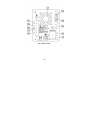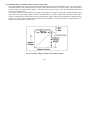
1
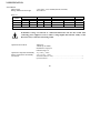
DC POWER SUPPLY
(Switching mode)
ISO-TECH IPS1820D RS Stock No. 357-0760
ISO-TECH IPS3610D RS Stock No. 357-0776
ISO-TECH IPS606D RS Stock No. 357-0782
82IP-3610DMB
Ei
SAFETY TERMS AND SYMBOLS
These terms may appear in this manual or on the product:
WARNING. Warning statements identify condition or practices that could result in
injury or loss of life.
CAUTION. Caution statements identify conditions or practice that could result in
damage to this product or other property.
The following symbols may appear in this manual or on the product:
DANGER
High Voltage
DANGER
Hot Surface
ATTENTION
refer to Manual
Ei
Protective
Conductor
Terminal
Equipotentiality
FOR UNITED KINGDOM ONLY
NOTE
This lead/appliance must only
be wired by competent persons
WARNING
THIS APPLIANCE MUST BE
EARTHED
IMPORTANT
The wires in this lead are
coloured in accordance with
the following code:
Green/
Yellow: Earth
Blue : Neutral
Brown: Live (Phase)
As the colours of the wires in main leads may not correspond with the colours marking
identified in your plug/appliance, proceed as follows:
The wire which is coloured Green & Yellow must be connected to the Earth terminal marked
with the letter E or by the earth symbol
or coloured Green or Green & Yellow.
The wire which is coloured Blue must be connected to the terminal which is marked with the
Letter N or coloured Blue or Black.
The wire which is coloured Brown must be connected to the terminal marked with the letter L
or P or coloured Brown or Red.
If in doubt, consult the instructions provided with the equipment or contact the supplier.
This cable/appliance should be protected by a suitably rated and approved HBC mains fuse;
refer to the rating information on the equipment and/or user instructions for details. As a guide,
cable of 0.75mm ² should be protected by a 3A or 5A fuse. Larger conductors would normally
require 13A types, depending on the connection method used.
Any moulded mains connector that requires removal/replacement must be destroyed by removal
of any fuse & fuse carrier and disposed of immediately, as a plug with bared wires is hazardous
if a engaged in live socket. Any re-wiring must be carried out in accordance with the information
detailed on this label.
Eii
Statement of Compliance
IPS-1820D, IPS-3610D, IPS-606D
are herewith confirmed to comply with the requirements set out in the Council Directive on the
Approximation of the Law of Member States relating to Electromagnetic Compatibility
(89/336/EEC,92/31/EEC,93/68/EEC) and Low Voltage Equipment Directive(73/23/EEC).
For the evaluation regarding the Electromagnetic Compatibility and Low Voltage Equipment Directive,
the following standards were applied:
EN 61326-1: Electrical equipment for measurement, control and laboratory use—EMC requirements (1997+A1:1998 )
Conducted Emission
Radiated Emission
Current Harmonic
EN 55022
Class A
(1994)+A1(1995)+A2(1997)
EN61000-3-2
Class A
(1995)/A12(1996)/A13(1997)/A1(1998)/A2(1998)/prA14(2000)
Voltage Fluctuation
EN61000-3-3
(1995)
Electrostatic Discharge
Radiated Immunity
Electrical Fast Transients
Surge Immunity
Conducted RF Immunity
Voltage Dip/Interruption
EN 61000-4-2
EN 61000-4-3
EN 61000-4-4
EN 61000-4-5
EN 61000-4-6
EN 61000-4-11
Low Voltage Equipment Directive 73/23/EEC
Low Voltage Directive
EN 61010-1:(1993)+A2:(1995)
Eiii
(1995)
(1996)
(1995)
(1995)
(1996)
(1994)
CONTENTS
SECTION
PAGE
1. INTRODUCTION…………………………………………………………………………….………………………
1
2. SPECIFICATIONS……………………………………………………………………………………………………
2
2-1 General…………………………………………………………………………………….…………………….
2
2-2 Constant Voltage Operation……………………………………………………………………………………
3
2-3 Constant Current Operation…………………………………………………………………………………...
3
2-4 Indicator Meter………………………………………………………………………………………………….
3
2-5 Insulation………………………………………………………………………………………………………...
3
3. PRECAUTIONS BEFORE OPERATION…………………………………………………………………………..
4
3-1 Unpacking the Switching Power Supply………………………………………………………………………
4
3-2 Checking the line voltage……………………………………………………………………………………….
4
3-3 Environment…………………………………………………………………………………………………….
5
3-4 Equipment installation and operation…………………………………………………………………………
5
4. THEORY OF OPERATION…………………………………………………………………………………………
6
5. PANEL CONTROLS AND INDICATORS…………………………………………………………………………
9
5-1 Front Panel………………………………………………………………………………………………………
9
5-2 Real Panel………………………………………………………………………………….…………………….
9
6. OPERATION INSTRUCTIONS…………………………………………………………………………………….
12
6-1 Precaution………………………………………………………………………………….…………………….
12
6-2 Setting Current Limit…………………………………………………………………………………………...
12
6-3 Constant Voltage/Constant Current Characteristic………………………………………………………….
13
6-4 Operation Mode…………………………………………………………………………………………………
14
7. MAINTENANCE……………………………………………………………………………………………………
15
7-1 Fuse Replacement……………………………………………………………………………………………….
15
7-2 Line voltage Conversion………………………………………………………………………………………...
15
7-3 Adjustment………………………………………………………………………………………………………
16
7-4 Cleaning………………………………………………………………………………………………………….
18
Eiv
1. INTRODUCTION
This series of switched mode power supplies have removed the inconvenience of big volumes and heavyweight
associated with traditional power supplies.
The output voltage and current are controlled by two variable resistors with coarse and fine regulation for simple and
precise adjustment.
Features:
l
l
l
l
l
l
Wide input voltage range— 97V~133V (for 115V) and 195V~265V (for 230V).
With high frequency operation the size of power the transformer is reduced
With small size, light weight and high power density.
Entire efficiency rate up to 70%.
Constant current and constant voltage modes.
Zero adjustment for the voltage and current output.
E1
2.SPECIFICATION
2-1. General
Mains supply
Rating, dimension and weight
: 115V/230V±15% 50/60Hz(Switch selectable).
: See Table 2-1.
Table 2-1
MAX. RATING
INPUT RATING
Voltage
Current
Watts
VA
IPS-1820D
18V
20A
500
900
IPS-3610D
36V
10A
500
900
IPS-606D
60V
6A
500
900
Dimensions:128(W) × 145(H) × 285(D) mm.
Model
FUSE STYLE & RATING
115V
230V
T 10A 250V
T 6.3A 250V
T 10A 250V
T 6.3A 250V
T 10A 250V
T 6.3A 250V
WEIGHT
kg
3.3
3.3
3.3
WARNING: Voltage over 60V DC is a lethal shock hazard to the user. Be careful when
connecting power supplies in series to achieve voltage higher than 60V DC totally or 60V
DC between any connection and earth ground.
Operation Environment
: Indoor use,
Altitude up to 2000m,
Installation Category II,
Pollution degree 2.
Operation Temperature &Humidity : 0℃ to 40℃, <80%.
Storage Temperature & Humidity : -10℃ to 70℃, <70%.
Accessories
: Test Lead (current < 4A)…………………………………………… × 1
Operation Manual ..………………………………………………………… × 1
E2
2-2.Constant Voltage Operation
(1) Output Voltage ranges from 0 to rated voltage with continuous adjustment.
(2) Voltage regulation
line regulation≦5mV.
load regulation≦5mV.
(3) Recovery time≦500µs(50% Load change, minimum load 0.5A).
(4) Ripple & Noise≦5mVrms, 100mVp-p (tested by 20MHz oscilloscope.)
(5) Temperature coefficient≦100ppm/℃.
2-3.Constant Current Operation
(1) Output current ranges from 0 to rated current with continuous adjustment.
(2) Current regulation
line regulation≦3mA.
load regulation≦3mA.
(3) Ripple & Noise≦3mArms (IPS-606D).
≦5mArms (IPS-3610D).
≦10mArms (IPS-1820D).
2-4.Indicator Meter
1)Voltage:
Display
: 3 1/2 Digits 0.39” Green LED display.
Accuracy
: ±(0.5% of reading + 2 digits).
2)Current:
Display
: 3 1/2 Digits 0.39” Red LED display.
Accuracy
: ±(0.5% of reading + 2 digits).
2-5.Over Voltage Protection
(1) Over Voltage Protection ranges from 5% rating to rating +5.5%.
(2) OVP Accuracy ±(Vset 1%+0.6V)
2-6.Insulation
Between Chassis and Output Terminal : ≧20MΩ (DC500V).
Between Chassis and AC Cord
: ≧30MΩ (DC500V).
E3
3. PRECAUTIONS BEFORE OPERATION
3.1 Unpacking the Switched ModePower Supply
The instrument has been fully inspected and tested before shipping from the factory. Upon receiving the instrument,
please unpack and inspect it to check if there is any damages caused during transportation. If any sign of damage is
found, notify the bearer and/or the dealer immediately.
3.2 Checking the Line Voltage
The instrument can be connected to any of the line voltages shown in the table below. Before connecting the power
plug to an AC line outlet, make sure the voltage selector on the rear panel is set to the correct position corresponding to
the line voltage. The instrument might be damaged if connected to the wrong AC line voltage.
WARNING: To avoid electrical shock the power cord protective grounding conductor must be
connected to ground.
When line voltages are changed, replace the required fuses shown below.
Line voltage
Range
Fuse
Line voltage
Range
Fuse
115V
97-133V
T 10A 250V
230V
195-265V
T 6.3A 250V
WARNING: To avoid personal injury, disconnect the power cord before removing the fuse
holder.
E4
3.3 Environment
The normal ambient temperature range of this instrument is from 0° to 40°C (32° to 104°F). Operation of the
instrument above this temperature range may cause damage to the circuits.
Do not use the instrument in a place where strong magnetic or electric fields exist as they may disturb the
measurement.
3.4 Equipment Installation, and Operation
Ensure there is proper ventilation for the vents in the IPS power supplies case. If this equipment is used in a manner
not according to the specification, the protection provided by the equipment may be impaired.
WARNING: This is a Class A product. In a domestic environment this product may cause
radio interference in which case the user may be required to take adequate measures.
E5
4.THEORY OF OPERATION
l
Block Configuration of IPS- System
The IPS-Series comprise a Bridge rectifier, a Pulse Width Modulation, a Driver Circuit, a Driver Transformer, a
Rectifier Circuit, a Voltage Control Circuit, a Current Shunt, an Output Filter, a Voltage/Current Adjusting Circuit, a
Buffer Circuit, an Error Amplifier, an Opto-Isolator, and an Auxiliary Switching Supply and etc.
l
Component List for each circuit configuration
Bridge Rectifier:
BD101.
Pulse Width Modulation:
U102.
Driver Circuit:
T104, Q105~Q108.
Driver Transformer:
T301.
Rectifier Circuit:
D301~D302.
Voltage Control Circuit:
Q303.
Current Shunt:
R341.
Output Filter:
Common Choke L302, C325.
Voltage/Current Adjusting Circuit:
U302.
Buffer Circuit:
U302, Q301.
Error Amplifier:
U301, U303.
Opto-isolator:
U304.
Auxiliary Switching Supply:
U201, U202, T201.
OVP:
U401, U402
Remote Control:
RL401, D402
E6
l
Description of Circuit Theory
1) +10V Voltage reference circuit:
Start up the circuits of R306 and D302 to ensure the output voltage of OPA U301, PIN 1 is in positive status when power is on.
At this moment, the output voltage of PIN 1 will pass through R307 to maintain the voltage of both ends of ZENER DIODE
ZD301(6.2V) to 6.2V. As OPA has the character of false short circuit, so U301 PIN3=6.2V, refer to the following formula:
VR301 + 4.99k + 10k
VR301 + R304 + R305
Vref = 6.2
= 6.2
@ 10V
10k
R305
Therefore, the OPA’s output voltage can be changed by adjusting the VR301 as shown in the following formula:
Vref=10V→VR301=1.14kΩ
2) Voltage Adjusting Circuit
The R311, and R313 are voltage feedback attenuating resistors while R312 is to control the output of Reference voltage. Please
refer to the following formula:
R311 + R313
R313
If Vref=10V R311=52.3kΩ R313=20kΩ
Vout = Vref
52.3k + 20k
72.3k
= 10
= 36.15V
20k
20k
And the R316, R317, C313, C314, and C315 are compensated circuits for voltage frequency.
Vout = Vref
3) Current Adjusting Circuit:
The U302 is an Error Amplifier with the gain at:
Io ´ R341 ´ A = 10V ´
A=
R326 100k
=
= 28.01
R342 3.57k
R321
= Vpin12 = Vpin13
R321 + R322 + VR303
For example: IPS-1820D, Io=20A,R341=10mΩ
Vpin12=Io×R341×A=20×0.01×28.01=5.602V
E7
l
Figure 1: Block Diagram
E8
5.PANEL CONTROLS AND INDICATORS
5-1.Front panel(Fig. 4-1)
(1)
CV Indicator
(2)
CC Indicator
(3)
Voltage coarse
(4)
Voltage fine
(5)
Current coarse
(6)
Current fine
(7)
“+” output terminal
(8)
“GND” terminal
(9)
“–“output terminal
(10) Meter
(11) Meter
(12) Power control
(13) Current HI/LO control
5-2.Rear panel(Fig. 4-2)
(14) Fuse holder
(15) Power socket.
(16) AC selects switch
(17)
(18)
(19)
(20)
(21)
(22)
(23)
(24)
Fan
+ sense terminal
– sense terminal
+ output terminal
– output terminal
Ground terminal
Remote Control
OVP ADJ
Lights when the power is on and in constant voltage operation.
Lights when in constant current operation.
For the coarse adjustment of the output voltage.
For the fine adjustment of the output voltage.
For the coarse adjustment of the output current.
For the fine adjustment of the output current.
Positive polarity (Red).
Earth and chassis ground (Green).
Negative polarity (Black).
Indicates the output voltage.
Indicates the output current.
On/Off switch.
Current indicates HI/LO range selection.
With 115V or 230V voltage and current ranges selection (Refer to the
diagrammatic instruction to prevent mis-operating).
Cooling fan.
Screw type + sense input terminal.
Screw type – sense input terminal.
Screw type + output terminal.
Screw type – output terminal.
Screw type ground terminal (connected to case chassis).
Short or open the remote control terminal for output on or off.
Adjust trimmer VR401 to set the OVP value.
E9
Fig. 4-1 Front Panel
E10
Fig. 4-2 Rear Panel
E11
6.OPERATION INSTRUCTIONS
6-1.Precaution
(1)AC input
AC input should be within the range of line voltage±15% 50/60Hz.
WARNING: To avoid electrical shock, the power cord protective grounding conductor must be
connected to ground.
(2)Installation
Avoid using the power supply in a place where ambient temperature exceeds 40℃. The heat sink located at rear of
the power supply must have sufficient space for radiation.
CAUTION: To avoid damaging the power supply, don’t use it in a place where ambient
temperature exceeds 40℃.
6-2.Setting Current Limit
(1) Determine the maximum safe current for the device to be powered.
(2) Temporarily short the (+) and (-) terminals of the power supply together with a test lead.
(3) Rotate the COARSE VOLTAGE control away from zero sufficiently to have the CC indicator lightened.
(4) Adjust the CURRENT control for the desired current limit. Read the current value on the Ammeter.
(5) The current limit (overload protection) has now been preset. Do not change the CURRENT control setting after this step.
(6) Remove the short between the (+) and (-) terminals and hook up for constant voltage operation.
E12
6-3.Constant Voltage / Constant Current Crossover Characteristic
The working characteristic of this series is called a constant voltage/constant current automatic crossover type. This permits
continuous transition from constant current to constant voltage modes in response to the load change. The intersection of
constant voltage and constant current modes is called the crossover point. Fig.5-1 shows the relationship between this
crossover point and the load.
For example, if the load is such that the power supply is operating in the constant voltage mode, a regulated output voltage
is provided. The output voltage remains constant as the load increases, up until the point where the preset current limit is
reached. At that point, the output current becomes constant and the output voltage drop is proportioned to further increases
in load. The crossover point is indicated by the front panel LED indicators. The crossover point is reached when the CV
indicator goes out and the CC indicator is on.
Fig. 5-1 Constant Voltage/Constant Current Characteristic.
E13
Similarly, crossover from the constant current to the constant voltage mode automatically occurs from a decrease in
load, a good example of this would be seen when charging a 12 volt battery. Initially, the open circuit voltage of the
power supply may be preset for 13.8 volts. A low battery will place a heavy load on the supply and it will operate in the
constant current mode, which may be adjusted for a 1 amp charging rate. As the battery becomes charged, and its
voltage approaches 13.8 volts, its load decreases to the point where it no longer demands the full 1 amp charging rate.
This is the crossover point where the power supply goes into the constant voltage mode.
6-4.Operation mode: Voltage Operation Mode:
A. Set Power switch to “OFF” position.
B. Make sure that line voltage is correct for the input power voltage.
C. Plug power cord into the power outlet.
D. Set Power switch to “ON” position.
E. Adjust “Voltage” and “Current” control to the desired output voltage and current.
F. Connect the external load to the output binding posts. Make sure both “+” and “-” terminals are connected correctly.
E14
7. MAINTENANCE
WARNING
The following instructions are used by qualified personnel only. To avoid electrical shock, do not perform any servicing
other than the operating instructions of the manual unless you are qualified to do so.
7-1.Fuse Replacement
If the fuse blown, the CV or CC indicators will not light and the power supply will not operate. The fuse should not
normally blow unless a problem has developed in the unit. Try to determine and correct cause of the blown fuse, then
replace only with a fuse of the correct rating and type.
The fuse is located on the rear panel (see Fig. 4-2).
WARNING: For continued fire protection. Replace with 250V fuse of the specified type and rating,
and disconnect the power cord before replacing fuse.
7-2.Line Voltage conversion
The primary winding of the power transformer is tapped to permit operation from 115/230 VAC, 50/60 Hz line voltage.
Conversion from one line voltage to another is done by change AC selects switch as shown in Fig. 4-2.
To convert to different line voltage, perform the following procedure:
(1) Make sure the power cord is unplugged.
(2) Set the AC switch to the desired line voltage position.
(3) The change of line voltage may also require a corresponding change of fuse value. Install correct fuse value
according to the instruction shown on rear panel.
E15
7-3.Internal adjustments
The unit was accurately adjusted at the factory before shipment. So, readjustment is suggested only when the accuracy
of circuit is affected by the repair, or when you have the reason to believe that the unit is out of accuracy. The
recommended calibration device is a multimeter with an accuracy of ±0.1% dcv or better.
If readjustment is required, proceed the following procedure. Locations of the adjustments are shown in Fig. 6-1 and
Fig.6-2.
(1) Adjustment of the Rating Voltage
A. Connect an accurate (±0.1%) external multimeter to measure the dc voltage at output terminals of the power
supply.
B. Set the COARSE and FINE VOLTAGE controls to maximum (fully clockwise).
C. Adjust trimmer VR301 for a reading on the multimeter to be 18.50V for IPS-1820D, 36.50V for IPS-3610D, and
60.50V for IPS-606D.
D. Adjust trimmer pot VR2 to set the reading value of voltmeter as same as the one shown on the multimeter..
(2) Adjustment of the rating Current
A. Set the CURRENT control to HI.
B. Set the COARSE and FINE CURRENT controls to minimum (fully counterclockwise).
C. Set the COARSE and FINE VOLTAGE controls to the center position.
D. Connect an external multimeter to measure dc current of output terminal.
E. Adjust trimmer VR304 to have a reading of –0.00A indicated on the current meter.
F. Set the COARSE and FINE CURRENT controls to maximum (fully clockwise)
G. Adjust trimmer VR303 for a reading on the multimeter to be 20.10A for IPS-1820D, 10.10A for IPS-3610D, and
6.10A for IPS-606D.
H. Adjust trimmer VR2 to set the reading value of voltmeter as the same as the one shown on the multimeter.
I. Set CURRENT control to LOW.
J. Adjust trimmer VR310 to set the reading value of voltmeter as 0.5 times to the rating current.
K. Adjust trimmer VR401 to set the OVP value.
E16
E17
7-4 Cleaning
To clean the power supply, use a soft cloth dampened in a solution of mild detergent and water. Do not spray cleaner
directly onto the instrument, since it may leak into the cabinet and cause damage. Do not use chemicals containing
benzine, benzene, toluene, xylene, acetone, or similar solvents. Do not use abrasive cleaners on any portion of the
instrument.
RS Components UK
PO Box 99, Corby
Northants, NN17 9RS
Tel: 01536 201234
Fax: 01536 405678
E18