1
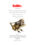
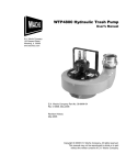
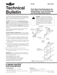
c User Guide Load Cushion™ Hydraulic Accumulator Kits 6850575, 6850576 for Cascade Attachments & Lift Truck Hoist Systems This User Guide contains a general description, application and installation information, troubleshooting, pre-charging, pressure checking and a parts list for Cascade Load Cushion™ Hydraulic Accumulators. General Description WARNING: Hydraulic accumulators may contain inert gas under high pressure. Read through entire User Guide before installing or servicing unit. Do not use on hydraulic systems over 4000 psi (275 bar). Accumulator Kits 6850575 (0.5 liter) and 6850576 (1.0 liter) are designed to be added to the hoist or attachment hydraulic systems on lift trucks with attachments weighing up to 4000 lbs (1815 Kg). They provide a cushioning effect in the hydraulic system to reduce shocks to the load and equipment. The Accumulator is a gas-over-oil type and requires a specific precharge of dry inert gas (water pumped nitrogen recommended). No maintenance is required, except for periodically checking the pre-charge and checking for hydraulic leaks. Applications Recommended applications for Load Cushion™ Accumulators are listed below, at the pre-charge pressures indicated: Attachment/Hydraulic Circuit 1 Forks only or no Attachment: mast hoist circuit. AC0192.eps Purpose Cushions load and hoist system during lifting, lowering, traveling. Accumulator Pre-Charge 350–400 psi (25 bar) or according to load. 2 Paper Roll Clamps: mast hoist circuit. (as above) Attachment weight's pressure equivalent in hoist main lift stage.➀ 3 Sliding Arm Clamps: mast hoist circuit. (as above) (as above) 4 Auto Clamp™: mast hoist circuit. (as above) (as above) 5 Adaptive Force Control (AFC): mast hoist circuit. (as above) Attachment weight's pressure equivalent in free lift stage as determined by controller.➁ Cushions load and pantograph mechanism from impacts during load packing. 6 Push-Pull: push circuit Part No. 6850675-R1 2500 psi (170 bar) ➀ Determine by connecting pressure gauge to Accumulator connection point (see schematic next page). ➁ Refer to Adaptive Force Control (AFC) Setup Instructions 6006350. cascade corporation For Technical Support . . . Call: 1-800-227-2233 OR Write: Cascade Corporation, P.O. Box 20187, Portland, OR 97294 To Order Parts . . . Call: 1-888-227-2233 OR Write: Cascade Corporation, 2501 Sheridan Ave., Springfield, OH 45505 Installation The Load Cushion™ Accumulator can be mounted in any position. However, it should be mounted rigidly, and oriented so that the warning label is visible and the gas charging valve is easily accessible. NOTE: Accumulator is normally shipped with zero pre-charge, check the nameplate. IMPORTANT: As an option, a shut-off valve is available to facilitate hydraulic system and attachment maintenance. 1 Use the end-clamps provided in the kit and determine a suitable mounting location on the truck cowl, mast or attachment frame. NOTE: Before drilling holes, check that the Accumulator is protected from damage during mast tilt, attachment operation, and load handling. If necessary, fabricate a mounting plate to provide a suitable location. Pre-Charging or Pressure Checking NOTE: Accumulator is normally shipped with zero pre-charge, check the nameplate. WARNING: Failure to read and follow these directions can cause rapidly discharging gas and/or hydraulic fluid which can result in death, personal injury and property damage. Accumulator should be charged with only clean, dry inert gas (water-pumped nitrogen recommended). Accumulator Charging Kit, Part No. 228235, is available from Cascade to pre-charge or pressure-check the Accumulator. If other charging equipment is used, make sure it is compatible with the gas valve assembly on the Accumulator. When pre-charging, it is strongly recommended that the nitrogen bottle be equipped with a high pressure regulator as shown opposite. 1 With the engine off, make sure pressure is relieved in the truck and Attachment hydraulic systems. Move truck auxiliary control levers to the OPEN or DOWN position to relieve any trapped pressure to tank. 2 If pre-charging, make sure nitrogen bottle valve is closed. Attach charging kit hose to nitrogen bottle as shown. NOTE: Hose is not necessary if checking Accumulator pressure only. 3 Remove Accumulator gas valve guard and protective cap. 4 Make sure gas chuck 'T' handle is screwed all the way out GA0134.eps 1 2 Remove protective cap (if installed) from hydraulic port fitting and install a No. 8-8 SAE 37 degree/O-Ring fitting provided in the kit. WARNING: Before removing hydraulic lines or hoses, relieve pressure in the hydraulic system. With the truck off, move the truck auxiliary control levers several times in both directions. Crack fittings slowly to assure pressure is released. 3 Connect the Accumulator into the hydraulic system in a 'Tee' configuration as shown: A Hoist Circuits: Accumulator must be between hoist cylinders and truck auxiliary valve. B Push circuits: Accumulator must be between push cylinders and attachment check valve, or an alternate check valve (Contact Cascade Service). Accumulator 'Tee' Connection Truck Auxiliary Valve 3 5 Close bleed valve on charging manifold and slowly screw gas chuck 'T' handle all the way in (CW) to open Accumulator gas valve. If pre-charging, proceed to Step 6. If pressure-checking, follow the procedures below: A Pressure Correct – Unscrew 'T' handle all the way out (CCW) and slowly open bleed valve to relieve gas trapped in charging manifold. NOTE: A small amount of gas is lost during each test, eventually requiring that gas be added to maintain the correct charge. B Pressure High – Slowly open (crack) bleed valve until desired pressure is indicated. Close bleed valve. Unscrew 'T' handle on gas chuck and open bleed valve to relieve gas trapped in charging manifold. C Pressure Low – Connect charging hose and proceed to Step 6. 6 Slowly open (crack) nitrogen bottle valve and slowly fill Accumulator to desired pre-charge indicated in Table on front page of this Manual. 7 Let pre-charge sit for 10–15 minutes and recheck pressure. If desired pre-charge is exceeded, close nitrogen bottle valve, disconnect hose, and slowly open bleed valve until desired pressure is indicated. Close bleed valve. Test Gauge Shut-Off Valve (CCW) and attach gas chuck to Accumulator gas valve as shown. If pre-charging, do not allow hose to twist or kink. Hoist Cylinders CAUTION: Do not attempt to reduce pre-charge in Accumulator by depressing valve core with foreign object. High pressure may rupture valve seat. 8 Screw gas chuck 'T' handle all the way out (CCW), then slowly open bleed valve to relieve gas trapped in charging manifold. 9 Using a wrench to prevent gas valve on Accumulator from Attachment Valve (or alternate) check valve Push Cylinders turning, remove gas chuck. 10 Replace gas valve cap and valve guard. capscrews to 15 in.-lbs. (17 cm kg). AC0197.eps Tighten valve cap 3 Troubleshooting & Maintenance • Verify accumulator operation during normally scheduled truck maintenance by checking for load cushioning effect in hydraulic circuit. Gas Valve Guard and Cap • Check for external hydraulic leaks at the accumulator fill valve, shutoff valve (if equipped), and hose connection. Accumulator Charging Kit (Part No. 228235) 'T' Handle Bleed Valve Gas Chuck Accumulator Gas Valve • Check for proper pre-charge pressure one week after installation, then every 1000 hours or 6 months, whichever occurs first (see Pre-charging or Pressure Checking, Steps 1 through 5. NOTE: Pre-charge pressure will be higher than normal if hydraulic fluid leaks into the gas side, and lower than normal if gas leaks into the hydraulic side (or externally past the end caps or charging valve). • The accumulator is not serviceable. If it does not hold the pre-charge, it should be replaced. Remove the accumulator from the system as described below. Charging Manifold Accumulator Removing from Hydraulic System If it is determined that internal or external leakage is occurring, the Accumulator must be discharged, and the unit removed from the hydraulic system. Use the following procedure: 1 Make sure that the Accumulator shut-off valve (if equipped) is open to avoid trapping pressure in the hydraulic side of the Accumulator. 3000 psi maximum bottle pressure (if regulator not used) 2 Turn the truck off and relieve pressure in the hydraulic system by moving the truck auxiliary control levers several times in both directions. 3 Remove Accumulator gas valve guard and protective cap. 4 Make sure gas chuck 'T' handle is screwed all the way out (CCW) and connect gas chuck to Accumulator gas valve as shown. 5 Make sure bleed valve is closed and screw gas chuck 'T' Nitrogen Bottle Valve High Pressure Regulator (Recommended) handle all the way in (CW) to open Accumulator gas valve. 6 Slowly open (crack) bleed valve and allow Accumulator to fully discharge. Close bleed valve. Gauge pressure should indicate zero. CAUTION: Do not attempt to discharge the Accumulator by depressing the valve core with a foreign object. High pressure may rupture the valve seat. 2 7 Use a wrench to prevent gas valve on Accumulator from turning and remove the gas chuck. Replace cap and valve guard on Accumulator. AC0186.eps Nitrogen Bottle WARNING: After completing any service procedure, always test the Attachment through 5 complete cycles. First test empty, then test with a load to make sure operation is correct before returning to the job. 8 Disconnect hydraulic connection to Accumulator and remove Accumulator from truck. NOTE: When reinstalling, the Accumulator must be pre-charged. Follow the procedure in Pre-charging or Pressure Checking on previous page. Load Cushion™ Accumulator Parts List 1 AC2529.eps 2 3 WARNING: Release pressure in unit before installing or storing. (see Pre-Charging or Pressure Checking for proper bleeding procedure). 4 AC0196.eps 5 Shut-off Valve AC2528.eps Charging Kit REF QTY 1 1 2 3 4 5 1 1 1 2 PART NO. 6850575 6850576 6850357 6850358 601377 6858865 227839 228235 DESCRIPTION Accumulator Kit w/Mount (0.5 liter) ● Accumulator Kit w/Mount (1.0 liter) ● Accumulator (4000 psi, 0.5 liter) Accumulator (4000 psi, 1.0 liter) Fitting, 8-8 SAE 37°/O-Ring Mounting Clamps Shut-off Valve Charging Kit ● Includes Items 1, 2 and 3. © Cascade Corporation 2014 10-2014 Part No. 6850675-R1