1
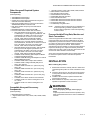
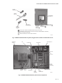
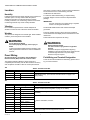
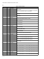
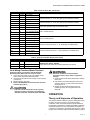
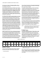
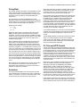
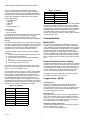
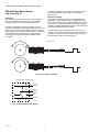
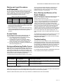
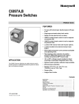
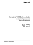
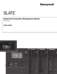
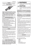
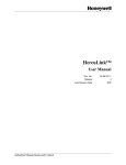
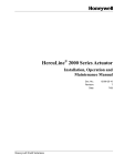
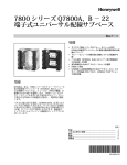
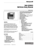
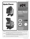
YP900A
Delphi Combustion Efficiency Panel
INSTALLATION INSTRUCTIONS
APPLICATION
The Honeywell Delphi YP900A Combustion Efficiency Panel
integrates loop- and logic-based fuel-air ratio control with O2
trim capability, flame safeguard control with VPS capability,
VFD control with feedback capability and a touchscreen
interface for burner and boiler applications. Commissioning,
control and monitoring is all accomplished through the
touchscreen interface.
The Delphi Combustion Efficiency Panel is a completed panel
assembly which consists of a RM7840L1075 burner safety
controller with wiring subbase, S7800A1142 Keyboard Display
Module, Built-in industrial panel PC with touchscreen display,
ABC900A loop and logic controller for load and O2 trim
control. Also included in the YP900A Combustion Efficiency
Panel assembly are O2 Sensor, mounting accessories and
Hall-effect speed sensor with tachometer.
Functions provided by the Delphi Combustion Efficiency Panel
assembly include automatic burner sequencing with VPS
(Valve Proving System), flame supervision, status and system
diagnostic indications, fuel/air ratio control with O2 trim to
provide complete combustion, PID modulating load control for
firing rate plus low fire hold capability.
The panel PC, ABC900A controller, and RM7840L burner
safety controller all communicate to provide accurate control
and time in commissioning and runtime modes. During
runtime mode, the display is used for monitoring, shutdown,
manual control, and setpoint changes. The ABC900A loop
and logic controller and RM7840L1075 burner safety
controller are responsible for the runtime operation.
This document provides installation instructions and operation
information. Other applicable publications are:
—
—
—
—
—
—
—
66-1191, YP900A Quick Start Guide
65-0084, Q7800A 22 Terminal Wiring Subbase
Product Data
66-1162, RM7840L1075 Relay Module with Valve
Proving Installation Instructions
65-0229, 7800 Series Relay Module Checkout and
Test
65-0288, S7800A1142 Keyboard Display Module
Product Data
65-0089, ST7800 Plug-in Purge Timer
60-2026, C7027, C7035, C7044, C7927 Minipeeper
UV Flame Detector
—
—
—
—
—
—
—
—
—
—
—
—
—
—
—
65-0267, C7961 Dynamic Self-checking Solid State
UV Flame Detector
60-0292, C7915 Infrared Flame Detector
65-0277, C7962 Visible Light Flame Detector
60-2024, C7007, C7008, C7009 Flame Rod Detector
95-8269, C7076 Adjustable Sensitivity UV Flame
Detector
60-2398, C7012 Ultraviolet Flame Detectors
50030542-1-EN, MF020 Oxygen Sensor Installation
Instructions
000670-1-EN, MF010 and MF020 Series Oxygen
Sensors
51-52-03-31, HC900 (ABC900) Hybrid Controller
Specification sheet
009558-1-EN, SNDJ-CNT Series Tachometers
005886-2-EN, LCZ Series Hall-effect Zero Speed
Sensors
65-0264 ML7999B Direct Coupled Actuator
63-2600 NXS VFD User Manual and Application
Manual
62-86-25-10 Operation Manual for HercuLine
2001-100/200/400-090-EC actuator
62-86-24-14 Quick Start Guide for HercuLine
2001-100/200/400-090-EC actuator
SPECIFICATIONS
Electrical Ratings
Power Supply: 110/120 Vac, 50/60 Hz, 20 A.
For individual ratings, see component literature for details.
Environmental Ratings
Enclosure: NEMA 12.
For individual ratings, see component literature for details.
General
Overall panel size: 30 in. high x 24 in. wide x 10.5 in deep
(including emergency stop button)
Panel weight: 80 pounds
Mounting holes are 0.44 in. typical diameter, 22.5 in. on center
Approval
Components are individually approved by the nationally recognized agencies. Please see component literature for
details. The panel has UL 508 approval.
Panel is assembled and wired to the UL Standards.
66-1190-03
YP900A DELPHI COMBUSTION EFFICIENCY PANEL
Table 1. Panel component list.
Honeywell OS
number
Description
YP900A1004
ABC900A1000
The ABC900 Advanced Boiler Control is a loop- and logic-based boiler control
platform. The ABC900A1000 OS number includes the CPU30 control, power supply,
shield kit, resistor kit, 4 slot I/O rack and 4 I/O cards: Analog input module, Analog
output module, Digital input module (Vac) and Digital output module (Vac).
Included
RM7840L1075
Programmable flame safeguard control with VPS (Valve Proving System) capability.
Included
Q7800A1005
Flame safeguard wiring subbase, panel mount for RM7840L control.
Included
S7800A1142
Keyboard Display Module for Modbus RTU communication, VPS and/or post-purge
timing programming.
Included
NOTE: When replacing the KDM, the modbus address must be set to 21 in the
field.
50050785-001
Fuel transfer delay printed circuit board.
Included
MF020-1-LC3
Oxygen sensor, high temperature, 15.7 inch (400mm) probe length, 0.01 to 3.6 psi (1
to 250mbar) pressure range, 0.1 to 25 volume % oxygen measuring range, 24Vdc
input, 4-20mA or 0-10Vdc output.
Included
NOTE: See “Oxygen Sensor” in Operation section for application details.
99-4218-14-07
Female cable connector, 7-pin, for MF020 oxygen sensor. RD 24 DIN 405 threaded
locking, screw termination, IP67 protection, non-shielded, Pg. 13.5 cable gland.
Included
SS-14M0-1-12BT Compression tube fitting, for MF020 oxygen sensor mounting. Stainless steel, 14mm Included (date
bore through with 3/4 inch male connection.
code
dependent)
SS-810-1-12BT
Compression tube fitting, for MF020 oxygen sensor mounting. Stainless steel, 1/2
inch bore through with 3/4 inch male connection.
LCZ460-30-ECC
Hall-effect zero speed sensor. Used for VFD speed measurement
Included
SNDJ-CNT-G02ECC
Tachometer with single channel, relay and 0-10Vdc output. Used for VFD speed
measurement and feedback.
Included
S900A1000
Dynics FX-12 touchscreen (12 inch) with Dynics BIX0 chassis/industrial panel PC or
equivalent, Solid state drive, 24Vdc.
Included
OTHER*
Islatrol Elite model EI-105, 5 amps, 120Vac high-frequency noise filter/surge
suppressor/line conditioner.
Included
OTHER*
Advantech model EKI-2525-AE 5-port industrial ethernet switch.
Included
OTHER*
IDEC Izumi model PS5R-SD24, 120Vac to 24Vdc, 60Watt, 2.5 amps switching power
supply for sensor power, plus a second one to power panel PC.
Included
OTHER*
•
•
•
•
•
•
•
•
•
•
•
Included
Finger Safe Relay, 120V Relay - SPDT, IDEC RJ1S-CL-A120
Finger Safe Relay Base - SPDT, IDEC SJ1S-07L
Finger Safe Relay, 120V Relay - SPDT, Veris Industries VMD1B-F120A
Finger Safe Relay Base - SPDT, Veris Industries VBD1B-F
Finger Safe Relay, 120V Relay - DPDT, Veris Industries VMD2B-F120A
Finger Safe Relay Base - DPDT, Veris Industries VBD2B-F
Emergency Off Switch, Square D XB4XBS8445
Alarm Reset Switch, Square D XB4BA61
System On/Off Switch, Square D XB4BD21
Supplemental circuit breaker, Square D, 60112, 15A
Supplemental circuit breaker, Square D, 60106, 5A
* Replacement is not available directly from Honeywell. It can be sourced from local supply house.
66-1190—03
2
Included (date
code
dependent)
YP900A DELPHI COMBUSTION EFFICIENCY PANEL
Other Honeywell Required System
Components
(Order separately)
— 7800 SERIES Flame Detector
— 7800 SERIES Flame Amplifier
— ST78xx Plug-in Purge Timer (30 seconds or longer for
automatic O2 sensor calibration)
— NXS Series Variable Frequency Drive c/w with add-on
32006630-002 Modbus connection card
— NXL Series Variable Frequency Drive with internal
modbus card
— ML7999B1002 Direct Coupled Actuator OR
— HercuLine 2001 Series Actuator and accessories:
— 2001-100-090-EC Herculine actuator, 100 Lb-in/
11.5N-M torque, 7 sec/90 degrees speed/travel. 100130Vac/60 Hz, 0/4-20mA or 0/1-5Vdc or 0-10Vdc
input, 0/4-20mA or 0/1-5Vdc or 0-16Vdc output,
UL/CSA, CCW rotation, Modbus RTU RS485.
— 2001-200-090-EC Herculine actuator, 200 Lb-in/
22.5N-M torque, 15 sec/90 degrees speed/travel.
100-130Vac/60 Hz, 0/4-20mA or 0/1-5Vdc or 0-10Vdc
input, 0/4-20mA or 0/1-5Vdc or 0-16Vdc output,
UL/CSA, CCW rotation, Modbus RTU RS485.
— 2001-400-090-EC Herculine actuator, 400 Lb-in/45NM torque, 30 sec/90 degrees speed/travel. 100130Vac/60 Hz, 0/4-20mA or 0/1-5Vdc or 0-10Vdc
input, 0/4-20mA or 0/1-5Vdc or 0-16Vdc output,
UL/CSA, CCW rotation, Modbus RTU RS485.
— 51452354-501EC Mounting plate adapter for Barber
Colman Series MP495 actuator.
— 51452354-502EC Mounting plate adapter for Landis &
Staefa SQM53/56 actuator.
— 51452354-503EC Direct couple valve hardware.
— 51452354-504EC Linkage assembly ball joint for
5/16 in. dia. pushrod.
— 51452354-505EC Pushrod 12 in. (304.5 mm) long,
5/16 in. dia.
— 51452354-506EC Pushrod 18 in. (457.2 mm) long,
5/16 in. dia.
— 51452354-507EC Pushrod 24 in. (609.6 mm) long,
5/16 in. dia.
— 51452354-508EC Pushrod 48 in. (1219.2 mm) long,
5/16 in. dia.
— 51452354-511EC North American valve retrofit kit.
— 51452354-513EC V51 valve mounting kit for 2.5 to
3 in. valves.
— 51452354-514EC V51 valve mounting kit for 4 in.
valves.
—
—
—
—
—
—
—
—
—
—
* Operating Control: L404, L408, L4008, L6008, P7810C
C6097 Gas/Air Pressure Switch
C437 Gas/Air Pressure Switch
V4046C/V8046C Pilot Gas Valve
V4295/V8295 Solenoid Gas Valve
V4297 Solenoid Gas Valve
V5055/V4055 Fluid Powered Gas Valve and Actuator
V5097/V4055 Fluid Powered Gas Valve and Actuator
V5197 Firing Rate Valve
V51E Butterfly Firing Rate Valve
NOTE: * Unless the device is approved as a combination of
Limit and Operating controller, separate devices
must be used for High limit, Low limit and Operating
control functions.
Process Variable/Firing Rate, Monitor and
Stack Transmitters
A 24Vdc loop powered transmitter with a 4-20mA output is
required by Delphi for the process variable/firing rate when
temperature or pressure are selected. Process variable setup is found on page 6 of the Software Settings pages. The
transmitter type and span is entered. When remote is
selected for the process variable, an external 4-20mA signal is
required for the firing rate. Delphi automatically scales the
remote input as 0-100%. Refer to the firing rate section of this
document for further details on remote setup.
24Vdc loop powered transmitters with a 4-20mA output must
be used for the optional monitor and stack temperature
transmitters.
INSTALLATION
When installing this product...
1.
2.
3.
4.
Read these instructions carefully. Failure to follow them
could damage the product or cause a hazardous condition.
Check the ratings given in the instructions and marked
on the product to make sure the product is suitable for
the application.
Installer must be a trained, experienced flame safeguard service technician.
After installation is complete, check out the product
operation as provided in these instructions.
WARNING
Compatible Honeywell Accessory
Components:
(Order separately)
— Q624/Q652 Ignition transformer
— * High Limit/Low Limit: L404, L4079, L408, L4008, L6008,
P7810C
3
Fire or Explosion Hazard.
Can cause property damage, severe injury or
death.
To prevent possible hazardous burner operation, verify
safety requirements each time a control is installed on
a burner.
66-1190—03
YP900A DELPHI COMBUSTION EFFICIENCY PANEL
4-20m A PROCESS
L404
VARIABLE
L4079
TRANSMITTER
HI LIMIT
LOW
WATE R
CUTOFF
BOILER
DE LPHI O2 COM BUSTION
EFFICIE NCY PANEL
L404
O 2 TRIM
SENSOR
FGR
DAM PER
OP CTL
C7004
C7005
C7008
C7009
C7012
C7015
C7024
C7027
C7035
C7044
C6097
FLAME
DETECTOR
C7061
C7915
C7927
C7961
C7962
FUEL AIR RATIO CONTROL, BURNE R
MANAGEME NT, O 2 TRIM , DISPLAY
A IRFLOW SW ITCH
IGN.
XFMR.
BURNER
MOTOR
Q624
Q652
A IR
DAM PE R
MOTOR
VPS (VALVE PROVING SYSTEM)
C6097
MANUAL
SHUT OFF
V ALVE
PRESSURE
RE GULATOR C437
C6097
LOW GAS
PRESS SW.
V4055
V 5055
V 5097
SAFETY
SHUT OFF
V ALVE 1
V 4055
V 5055
V 5097
VFD
V
V5197A
V51E
C437
C6097
MANUAL
SHUT OFF
V ALVE
SAFE TY
SHUT OFF
V ALVE 2
V 4297
V 4295/V 8295
V 4046C/V 8046C
MODULATING
VALVE
V
HIGH GAS
PRE SS SW.
PILOT
V ALVE
PI
Fig. 1. Typical boiler application with Delphi YP900A and other peripheral components.
66-1190—03
4
SPEED
SENSOR
M31105D
YP900A DELPHI COMBUSTION EFFICIENCY PANEL
SENSOR
CONNECTOR
OXYGEN
SENSOR
TOUCHSCREEN
INDUSTRIAL PC
HALL-EFFECT
SPEED SENSOR
SYSTEM
ON/OFF
SWITCH
SENSOR
MOUNTING
FITTING
EMERGENCY
STOP BUTTON 2
BURNER ALARM
RESET BUTTON
3
1
1
THIS SWITCH WILL DISABLE THE BURNER CONTROL WHEN IN OFF POSITION.
2
THIS EMERGENCY STOP BUTTON WILL SHUTDOWN THE BOILER WHEN DEPRESSED. ON RELEASE,
RESET OF THE RM7840 IS REQUIRED.
3
BURNER ALARM RESET BUTTON WILL RESET THE RM7840
M31104A
Fig. 2. YP900A Combustion Efficiency Panel, Oxygen Sensor, hardware and Hall-effect sensor.
INDUSTRIAL
PANEL PC
TB0
ABC900A1000
COOLING FAN
RM7840L1075
WITH S7800A1142
RELAYS
TB2:
T40-T100
120VAC
POWER
INPUT(TB3)
ETHERNET
SWITCH
TB1:
T1-T37
TACHOMETER
GROUNDING BAR
24 VDC
POWER
SUPPLIES
POWER
CONDITIONER
M31103A
Fig. 3. YP900A Combustion Efficiency Panel internal components.
5
66-1190—03
YP900A DELPHI COMBUSTION EFFICIENCY PANEL
Location
prior factory consent in writing, unless the wiring modifications
are documented on the control drawing. No other
modifications are authorized.
Humidity
Install the panel where the relative humidity never reaches the
saturation point. The relay module inside the panel is
designed to operate in a maximum 85 percent relative
humidity continuous, non-condensing, moisture environment.
Condensing moisture may cause a safety shutdown.
Vibration
For reference and troubleshooting, a complete wiring
schematic diagram can be found in the Delphi literature
package.
IMPORTANT
Run line voltage and low voltage wiring in separate
conduit to avoid signal interference.
Do not install the panel where it could be subjected to
vibration in excess of 0.5G continuous maximum vibration.
Terminate ML7999B actuator wire shield at the Delphi
ground bar.
Weather
Power the variable frequency drive (VFD) from a different
circuit breaker than the Delphi panel to avoid electrical noise
interference.
The panel is not designed to be weather tight. When installed
outdoors, protect the panel from the weather.
WARNING
Fire or Explosion Hazard.
Can cause property damage, severe injury or
death.
To prevent possible hazardous burner operation, verify
safety requirements each time a control is installed on
a burner.
Panel Wiring
All wiring shall be in accordance with the National
Electrical Codes (NEC) and local electrical codes.
WARNING
Electrical Shock Hazard.
Can cause serious injury, death or equipment
damage.
Disconnect the power supply before beginning
installation to prevent electrical shock, equipment and
control damage. More than one power supply
disconnect may be required.
Field Wiring and Terminal Designation
The Delphi Combustion Efficiency Panel arrives as a
completed panel assembly and has been tested for accuracy
and compliance. DO NOT re-wire the control panel without
TB0
Field knockouts are required for the wiring.
There are three terminal blocks for field wiring, please refer to
Fig. 3 for their locations.
Table 2. Terminal block TB0.
Terminal #
To Connecting Device
+
+
Data +
-
-
Data -
S
S
Common
Description
VFD (Modbus RTU) - (see “O2 Trim and VFD Control” on page 11 for
setting details)
TB1
Table 3. Terminal block TB1.
Terminal #
To Connecting Device
1
+
Transmitter +
2
-
Transmitter -
3
+
FR Signal +
4
-
FR Signal -
5
1
+24Vdc, power
6
2
0Vdc, common
7
4
Test input, +24Vdc
8
5
Output, 4-20mA
9
6
Output, Digital
10
7
Ground
11
+
Transmitter +
12
-
Transmitter -
66-1190—03
Description
Process Variable/Firing Rate (Temperature or Pressure), 24Vdc loop
powered, 4-20mA (see “Firing Rate” on page 11 for details)
BMS/SCADA -- Firing Rate Control, 4-20 mA (see “Firing Rate” on page 11
for details)
O2 Sensor Transmitter, 4-20 mA
Monitor Transmitter, 24Vdc loop powered, 4-20 mA
6
YP900A DELPHI COMBUSTION EFFICIENCY PANEL
Table 3. Terminal block TB1. (Continued)
13
+
Transmitter +
14
-
Transmitter -
15
+
4-20mA +
Air Actuator/Channel 3, command, 4-20 mA
16
-
4-20mA -
Air Actuator/Channel 3, command, common
* When ML7999 is used, jumper “4-20mA-” and “FB-” terminals.
17
FB+
Feedback signal +
Air Actuator/Channel 3, position feedback (ML7999 red wire),
>0 --- <5 Vdc (ML7999B); 0 --- 5Vdc (HercuLine)
18
FB-
Feedback signal -
Air Actuator/Channel 3, feedback, common (ML7999 common)
* When ML7999 is used, jumper “4-20mA -” and “FB-” terminals.
19
PH
Feedback, high ref
Air Actuator/Channel 3, feedback pot. high reference voltage (ML7999
black wire).
* When HercuLine actuator is used, no connection to PH is needed.
20
+
4-20mA +
Fuel 1 Actuator, command, 4-20 mA
21
-
4-20mA -
Fuel 1 Actuator, command, common
* When ML7999 is used, jumper “4-20mA -” and “FB-” terminals.
22
FB+
Feedback signal +
Fuel 1 Actuator, position feedback (ML7999 red wire)
>0 --- <5 Vdc (ML7999B); 0 --- 5Vdc (HercuLine)
23
FB-
Feedback signal -
Fuel 1 Actuator, feedback, common (ML7999 common)
* When ML7999 is used, jumper “4-20mA -” and “FB-” terminals.
24
PH
Feedback, high ref
Fuel 1 Actuator, feedback pot. high reference voltage (ML7999 black wire).
* When HercuLine actuator is used, no connection to PH is needed.
Stack Temperature Transmitter, 24Vdc loop powered, 4-20 mA
25
+
4-20mA +
Fuel 2 Actuator, command, 4-20 mA
26
-
4-20mA -
Fuel 2 Actuator, command, common
* When ML7999 is used, jumper “4-20mA -” and “FB-” terminals.
27
FB+
Feedback signal +
Fuel 2 Actuator, position feedback (ML7999 red wire)
>0 --- <5 Vdc (ML7999B); 0 --- 5Vdc (HercuLine)
28
FB-
Feedback signal -
Fuel 2 Actuator, feedback, common (ML7999 common)
* When ML7999 is used, jumper “4-20mA -” and “FB-” terminals.
29
PH
Feedback, high ref
Fuel 2 Actuator, feedback pot. high reference voltage (ML7999 black wire).
* When HercuLine actuator is used, no connection to PH is needed.
30
+
4-20mA +
FGR/Channel 4 Actuator, command, 4-20 mA
31
-
4-20mA -
FGR/Channel 4, command, common
* When ML7999 is used, jumper “4-20mA -” and “FB-” terminals.
32
FB+
Feedback signal +
FGR/Channel 4, position feedback (ML7999 red wire)
>0 --- <5 Vdc (ML7999B); 0 --- 5Vdc (HercuLine)
33
FB-
Feedback signal -
FGR/Channel 4, feedback, common (ML7999 common)
* When ML7999 is used, jumper “4-20mA -” and “FB-” terminals.
34
PH
Feedback, high ref
FGR/Channel 4, feedback pot. high reference voltage (ML7999 black
wire).
* When HercuLine actuator is used, no connection to PH is needed.
35
R
Red, Power supply
36
W
White, Signal output
37
B
Black, Common
38
S
Silver, shield
Hall Effect Blower Speed sensor (0-3000 RPM), loop powered 4-20 mA
(Required for blower motor position feedback when using VFD)
7
66-1190—03
YP900A DELPHI COMBUSTION EFFICIENCY PANEL
TB2
Table 4. Terminal block TB2.
Terminal #
40
To Connecting Device
F
41
G
Ground
42
L1 *
*
43
L1 *
Shutter *
44
L2 *
*
45
L1
Pilot valve L1
46
L2
Pilot valve L2
47
L1
Blower motor L1
48
L2
Blower motor L2
49
L1
Oil pump L1
50
L2
Oil pump L2
51
L1
Ignition L1
52
L2
Ignition L2
53
L1
Fuel 1 MV L1
54
L2
Fuel 1 MV L2
55
L1
Fuel 1 MV L1
56
L2
Fuel 1 MV L2
57
L1
Fuel 2 MV L1
58
L2
Fuel 2 MV L2
59
L1 OUT Dry contacts
60
L1 IN
Dry contacts
61
L1
Alarm L1
62
L2
Alarm L2
63
L1 IN
Dry contacts
64
L1 OUT Dry contacts
65
L1 IN
66
L1 OUT Dry contacts
Dry contacts
67
L1 IN
68
L1 OUT Dry contacts
Dry contacts
69
L1 IN
70
L1 OUT Dry contacts
Dry contacts
71
L1 IN
72
L1 OUT Dry contacts
Dry contacts
73
L1 IN
74
L1 OUT Dry contacts
Dry contacts
75
L1 IN
76
L1 OUT Dry contacts
Dry contacts
77
L1 IN
78
L1 OUT Dry contacts
Dry contacts
79
L1 IN
80
L1 OUT Dry contacts
Dry contacts
81
L1 IN
82
L1 OUT Dry contacts
Dry contacts
83
L1 IN
84
L1 OUT Dry contacts
66-1190—03
Description
Flame Signal
Dry contacts
Flame Detector
* Required for certain detector types only. See RM7840L and applicable
flame detector specification sheets for wiring details
Pilot Valve
Blower Motor
Remote Oil Pump (DO NOT jumper if not used)
Ignition Transformer
Fuel 1 Main Valve 1
Fuel 1 Main Valve 2
Fuel 2 Main Valve(s)
Valve Proving Switch (VPS)
120Vac Alarm Output
Main Valve Proof of Closure (Pre-ignition Interlock)
Limit # 1 – If not used, place jumper between terminals
Limit # 2 – If not used, place jumper between terminals
Limit # 3 – If not used, place jumper between terminals
Air Flow Switch
Fuel 1 Lockout Interlock # 1 – If not used, place jumper between terminals
Fuel 1 Lockout Interlock # 2 – If not used, place jumper between terminals
Fuel 1 Lockout Interlock # 3 – If not used, place jumper between terminals
Fuel 2 Lockout Interlock # 1 – If not used, place jumper between terminals
Fuel 2 Lockout Interlock # 2 – If not used, place jumper between terminals
Fuel 2 Lockout Interlock # 3 – If not used, place jumper between terminals
8
YP900A DELPHI COMBUSTION EFFICIENCY PANEL
Table 4. Terminal block TB2. (Continued)
85
L1 IN
Dry contacts
86
L1 OUT Dry contacts
87
L1 IN
88
L1 OUT Dry contacts
89
L1 IN
90
L1 OUT Dry contacts
91
L1
Device L1
92
Load
Device Load
93
L1
Fuel 1 actuator power
Dry contacts
Dry contacts
Lockout Interlock # 4 – If not used, place jumper between terminals
Lockout Interlock # 5 – If not used, place jumper between terminals
Lockout Interlock # 6 – If not used, place jumper between terminals
Push button provides reset for an external device
94
L2
Fuel 1 actuator neutral Fuel 1 Actuator (Power)
Ground
G
Fuel 1 actuator ground
95
L1
Fuel 2 actuator power
96
L2
Fuel 2 actuator neutral Fuel 2 Actuator (Power)
Ground
G
Fuel 2 actuator ground
97
L1
Air actuator power
98
L2
Air actuator neutral
Ground
G
Air actuator ground
99
L1
Actuator power
100
L2
Actuator neutral
Ground
G
Actuator ground
TB3
Channel 3 Actuator (Power), i.e. Air, depending on installer setup
Channel 4 Actuator (Power), i.e. FGR, depending on installer setup
Table 5. Terminal block TB3 (120 Vac Power Input).
Terminal #
To Connecting Device
L1
L1
Panel power
N
L2
Panel neutral
Ground
G
Panel ground
Description
120VAC Power Supply, 20A Max.
Provide disconnect means and overload protection as required.
Final Wiring Check and Static Checkout
All wiring shall be in accordance with the National
Electrical Codes (NEC) and local electrical codes.
1. Check the power supply circuit. The voltage and frequency must match the specification listed.
2. Check wiring terminations and routings to ensure proper
connections.
3. Restore power to the panel.
4. Refer to the RM7840L Product Instruction sheet for
Checkout procedures.
CAUTION
Test each limit and interlock to ensure system
operates correctly as defined in the 7800 Series
“Checkout and Test” document (Form # 65-0229).
WARNING
Explosion and Electrical Shock Hazard.
Can cause serious injury, death or equipment
damage.
1. Close all manual fuel shutoff valves before starting
these tests.
2. Use extreme care while testing the system. Line
voltage is present on most terminal connections
when power is on.
3. Replace all limits and interlocks that are not
operating properly. Do not bypass limits and
interlocks.
OPERATION
Theory and Sequence of Operation
The Delphi Combustion Efficiency Panel is designed to keep
the fuel to air ratio to a minimum to provide complete
combustion. While each boiler will have specific limitations,
the algorithm is designed to maintain repeatability regardless
of the boiler design once the commissioning is complete. To
minimize fuel consumption, the installer may choose to enable
Oxygen Trim to allow the Delphi Combustion Efficiency Panel
9
66-1190—03
YP900A DELPHI COMBUSTION EFFICIENCY PANEL
to trim the air in order to achieve the O2 setpoint. This is
accomplished by adding to or subtracting from the output to
the Air Damper and/or VFD.
time, the burner will shut down and will require manual reset.
A lockout will be annunciated on the display and the Delphi
alarm contact will be energized.
Each Honeywell actuator (servo) is equipped with a 4-20mA
input for accurate positioning and a 0-5 Vdc output to indicate
position feedback. Each actuator must be set up according to
manufacturer's guidelines (see ML7999B/Herculine actuator
product sheets for details) prior to completing setup through
the Delphi Combustion Efficiency Panel. Actuator setup is
completed though the display, where the Delphi learns the
span and direction of the actuators. There is no need to set
the direction of the actuator since Delphi will learn this during
the actuator commissioning.
The Delphi Combustion Efficiency Panel will continuously
monitor the acturator/VFD feedback on the curve and will
compare them to the baseline curve (setup during
commissioning). Should any portion of the curve not match
the baseline curve, the burner will shut down and will require
and manual reset. A lockout will be annunciated on the
display and the alarm contact will be energized. When the
oxygen transmitter is enabled and functioning properly, the O2
level will continuously be compared against the baseline
curve. If the excess air oxygen level deviates from the
baseline more than 20% of the measured value, the O2 Trim
functionality will be disabled and the burner will be shut down.
An alert will be generated and must be cleared before the O2
Trim function will be re-enabled. At that time, the O2 trim
sensor and O2 trim function can be disabled, if desired, and
the burner can be started again.
On a call for heat, the Delphi Combustion Efficiency Panel will
close the ABC Limit relay and the ABC Interlock circuit. This
will allow the RM7840 to initiate a safe start and start the
burner. Please refer to the RM7840 I & I Sheet for a detailed
sequence. Once the burner is released to Modulate by the
RM7840 controller, the ABC900 will sequence the actuators
and VFD to maintain the process variable Firing Rate Loop
Setpoint or will respond to the remote firing rate control signal,
depending on the setup. Once the Firing Rate Loop Setpoint
is met, the burner will remain in low fire. If the process variable
continues to rise due to low load, as measured by the process
variable transmitter, the burner will cycle off when the Process
Variable Max Value setpoint is reached. It will restart once the
measured process variable drops below the value of the
Process Variable Max Value minus the Offset (differential)
value, provided the external mechanical limits and operating
control are made. The mechanical limits are also in place and
will also cause the burner to cycle off in the event the limit(s)
are opened for any reason.
Delphi will continuously monitor the actual speed of the blower
motor to ensure the motor is running at the expected speed,
by monitoring the actual RPM feedback of the blower motor.
This is achieved via a separate input from a tachometer, which
receives a signal from a Hall-effect zero speed sensor,
mounted within 2mm of the keyed shaft. If the shaft is not
keyed, a suitable replacement location shall be determined by
the installer. The expected speed is stored in the curve during
the commissioning process. If the blower motor is running
lower than the expected speed, for an extended period of
The Display, ABC900A loop and logic controller and RM7840L
Burner Controller all communicate to provide accurate control
and time in commissioning and runtime modes. During
runtime mode, the display is used for monitoring, shutdown,
manual control, and setpoint changes. The ABC900A and
RM7840 are responsible for the runtime operation.
NOTE: If panel power has been shut off and there is a call
for heat present upon power up, there may be a
delay in the start command to the burner control
while the system updates itself.
Profile Curve
The Delphi Combustion Efficiency Panel provides 11 curve
steps with a separate light-off point. Light-off and minimum
modulation are separate points, however, light-off is not
shown on the profile curve. During curve commissioning,
light-off is shown as a separate point. After light-off the panel
goes to Step 1/Firing Rate 0%, which is the minimum
modulation point. Light-off can be different (lower or higher)
than Step 1/Minimum Modulation. See Table 6. For further
information, refer to the Quick Start Guide,
form #66-1191
Table 6. Profile Curve
Step
Firing
Rate
Purge Light off
-
-
1
0%
2
3
4
5
6
7
8
9
10
11
10%
20%
30%
40%
50%
60%
70%
80%
90%
100%
Purge Light off Min
Mod
Max
Mod
Monitor Points
• Montior Value (F, C, GPM, LPM, PSI, kPa, PPM, %RH,
Lbs/Hr, in. w.c., CFH)
There are two extra points that can be used for monitoring
purposes. Proper transmitters/sensors must be used and
connected to the system. These monitor points include:
When enabled, these points will be displayed on the monitor
screens. A history will also be enabled and will be displayed
on the Transmitter Chart in the Touch Screen Interface. These
monitor points can be named as appropriate in the set up
screen page.
• Stack Temperature
66-1190—03
10
YP900A DELPHI COMBUSTION EFFICIENCY PANEL
Firing Rate
The process variable of the boiler is user selectable to control
leaving water temperature or leaving steam pressure via a
Loop Powered 24Vdc, 4-20ma transmitter connecting to TB1
terminals # 1 & 2 (see Table 3). The default selection is
Temperature.
The Firing Rate is set using an ABC900A PID control
algorithm to determine the appropriate firing rate to satisfy the
process setpoint. The setpoint is user adjustable via the touch
screen interface with the installer level password.
Default PID rate settings:
P = 15
I = 1.46
D = 0
Delphi also allows users to control firing rate via a remote
BMS or SCADA system instead of the Process Variable
transmitter. If remote control is selected, the BMS or SCADA
system must be connected to TB1 terminal # 3 & 4 (see Table
3). The process variable set-up is found on page 6 of the
Software Settings pages.
When the Remote Process Variable option is selected, the
Firing Rate is calculated by the BMS and delivered to the
Delphi system via the BMS. When Remote is selected, the
scaling is automatically set as 0% to 100% and the PV value
equals the Firing Rate %. The PV Max Value must be set to a
value over 100 and the Low Fire Hold Setpoint must be set at
0% when Remote is selected. The PV Max Value and the Low
Fire Hold Setpoint can be found on Software Settings Page 1.
The PID can be set to Auto-Tune mode in the Settings section
of the Touch Screen Interface. This mode will allow the loop to
learn the best parameters to control the PID loop. You should
only use this mode if the default settings are not acceptable.
The Auto-Tune algorithm will automatically shut off after two
hours.
Manual Mode can be enabled from the touch screen interface.
This mode allows the operator to control the firing rate
independent of the temperature or pressure. If this mode is
selected, the high limit is still active.
Actuators
The Honeywell ML7999B or HercuLine actuators are used
with the Delphi panel. Actuators can be mixed or matched on
a panel. For instance, on a panel, a ML7999 could be used
for the fuel valve and a HercuLine for the air damper.
Delphi will continuously monitor the actuator positions relative
to the baseline curve setup during commissioning. Should
any portion of the curve not match the baseline curve, the
burner will shut down and will require manual reset.
Each actuator must be setup according to the manufacturer's
guidelines (see ML7999B/Herculine actuator product sheets
for details) prior to completing setup through the Delphi
Combustion Efficiency Panel. When performing the
preliminary actuator setup, the actuator must be connected to
the modulating device it controls and the contractor must
ensure the actuator command endpoints don't run up against
the mechanical fixed stops of the device. Note that tolerances
may shift after burner warm-up and adjustments may be
necessary to the modulation endpoints.
If an actuator feedback error occurs at or near the modulation
endpoints, check the modulating device's physical endpoint(s)
versus the commanded endpoint(s) to verify they do not
overlap.
The ML7999B preliminary actuator setup requires a 4-20mA
signal. The 4-20mA signal must come from a separate
current source other than Delphi. Preliminary setup occurs
before the actuator span and direction is learned by Delphi,
which is the final actuator setup step.
O2 Trim and VFD Control
If the O2 Transmitter is installed and enabled the system will
monitor the O2 Transmitter and will shut the boiler down if the
O2 level drops below 1% or has a sensor fault as determined
by the ABC900A controller. If used, the sensor is wired for
fault-proof operation and is monitored by Delphi. If the sensor
should fail, Delphi will shut down the boiler and provide
notification. The alarm must be acknowledged by the user in
order to reset the burner. At that point, the O2 sensor can be
disabled and the burner restarted. The control will follow the
curve and not trim.
When the O2 Trim is enabled, the output to the air actuator
and/or the Variable Frequency Drive will be adjusted,
depending on the setup as established in the Software
Settings pages, to add or subtract Air to satisfy the O2
Setpoint. If a VFD and an Air actuator are used, both will be
trimmed. The system can be configured to run without the
VFD. If O2 trim is selected without the VFD enabled, the
system will only trim the Air Damper. Channel 3 must be
selected and used for the Air damper when a VFD is not used.
If a VFD is used, Channel 3 can be used for another purpose
and the VFD is the only channel trimmed during O2 Trim.
If VFD bypass is desired, the user must buy a VFD with that
feature built-in. When using a VFD with bypass, an air damper
actuator should be used, to ensure air control is maintained.
11
66-1190—03
YP900A DELPHI COMBUSTION EFFICIENCY PANEL
Due to the scaling factors and Modbus polling address
settings, the VFD (Variable Frequency Drive) must be the
Honeywell NXS Series with add-on 32006630-002 Modbus
connection card or the NXL Series with internal modbus card.
Please refer to NXS/NXL product sheet for setup details.
Modbus RTU settings:
• 19.2K Baud Rate
• 8 Start Bits
• 9 Stop Bits
• Parity = 1
• Modbus Address = 10
Speed settings:
• 0 Hz minimum
• 60 Hz maximum
Complete Delphi-specific parameters for the Honeywell NXS/
NXL series VFD can be downloaded from Honeywell’s
website: http://customer.honeywell.com/vfd. Click the
Software Downloads link and download the file named Delphi
NXS.par.
To install the downloaded file onto the VFD drive, the NCDrive
software is needed (it can be downloaded from the same web
site). After installing the NCDrive program, connect a laptop to
the VFD drive with a cable (part number 32006629-011).
Details can be found in the NCDrive software Help file.
To upload the Delphi-specific parameters for the NXS/NXL
Series VFD:
1. Download and save Delphi application to folder on PC.
2. Download and install NCDrive.
3. Connect the PC to the VFD using cable (32006629011).
4. Run NCDrive and load Delphi application.
5. Upload the application to the VFD.
The oxygen sensor is automatically calibrated during each
purge cycle if a ST78xx plug-in purge timer of 30 seconds or
longer is used for the RM7840L control.
The O2 Setpoint has two options for control. The first is Basic
which allows for the same setpoint to be used regardless of
the Firing Rate. In some applications it may be desired to
have a different setpoint at each of the 11 steps in the curve.
The Multi/Advanced setpoint mode allows the user to set
individual setpoints based on the Firing Rate and is set up in
the settings section of the Touch Screen Interface. The setting
page is similar to the table 1 below. The default setting for O2
Setpoint is 4.0% in Basic and Multi/Advanced Mode.
Table 7. O2 Setpoint.
Firing Rate
O2 Setpoint
0
4.0
10
4.0
20
4.0
30
4.0
40
4.0
50
4.0
60
4.0
66-1190—03
Table 7. O2 Setpoint.
Firing Rate
O2 Setpoint
70
4.0
80
4.0
90
4.0
100
4.0
When the O2 Transmitter is disabled, O2 Trim is also disabled
and the O2 Transmitter Shutdown commands are disabled.
This allows the system to run on the curve entered by boiler
technician during commissioning. Delphi monitors feedback of
all enabled servos/VFD and will shut down the burner if the
servo/VFD feedback does not match the commanded
position. This is done to prevent an unsafe condition should a
mechanical failure occur.
Communication
Modbus RTU
The communication between the ABC900A loop and logic
controller and the RM7840L Burner Controller is dependent
on the S7800A1142 Keyboard Display Module being properly
installed on the RM7840L controller. Delphi is pre-configured
and functionally ready. The boiler will not operate if the
module is removed or the node address has been changed
(NOTE: the S7800A1142 modbus address setting should be
21). The ABC900A receives important information from the
burner controller and the connection must remain intact at all
times.
System Operator Interface / Display
The Delphi Combustion Efficiency Panel includes an Industrial
Panel PC on the front panel to provide system commissioning,
monitoring and status display functions. The display uses a
wizard-like process to assist you through the commissioning
process. Please refer to the Quick Start Guide (Form # 661191) for commissioning and burner setup instructions.
The display screen goes blank after 15 minutes of inactivity.
To re-activate the screen, simply touch it.
Oxygen Sensor - MF020
Life Expectancy
Shelf life of Honeywell oxygen sensor (Ziconium dioxide
technology) is theoretically infinite because there are no
components inside which can be “used up” or degrade. Other
sensors based on an electromechanical principal produce
current and will degrade over time.
Application Life
Typical life for a sensor used in clean air is approximately 10
years. If the combustion environment is polluted, life can be
shortened. In a very polluted or dirty environment, the porous
sensor cap (which acts as a filter) may block the exchange
from measured gas to the sensing element.
Temperature Range at Probe Tip
The temperature specifications for the oxygen sensor tip are: 148F to +752F (-100C to +400C).
Do not exceed these temperature limits.
12
YP900A DELPHI COMBUSTION EFFICIENCY PANEL
Sensor Self-Testing
The system conducts a O2 sensor self-test automatically at
the start of each burner cycle. Fresh atmospheric air on the
O2 sensor is required. Therefore, it is important to select plugin purge timer used on the RM7840L for 30 seconds or longer.
Use with other fuels
Methane
Methane will cause some O2 to be burned inside the sensor,
leading to a small drop in the measured levels of O2. It should
be small.
Hydrogen
The sensor can not be used for oxygen measurement in a
vacuum, or at very low Oxygen pressures (concentrations)
13
< 1%. The sensor is not suitable to operate in an H2
environment. Even at small percentages of H2 (i.e. 2%),
Oxygen will recombine with H2 and there will be errors in the
readings. At 50% of H2 sensor will not work any more.
Heavy Oil (#6)
In general, burning of heavy oil produces soot, which would
clog the porous sensor cap. This has not been tested or
confirmed, but in general it is not suited for heavy oil
applications.
For more information on testing with other fuels, please
contact Honeywell.
66-1190—03
YP900A DELPHI COMBUSTION EFFICIENCY PANEL
VFD Hall Effect Speed Sensor
(Fig. 4 and Fig. 5)
For proper application, only a single ferro-magnetic mass or
discontinuity should be sensed with the YP900 panel
Refer to Fig. 4.
Application
The LCZ Hall-effect zero speed sensor is used for blower
motor speed feedback to Delphi when a VFD (Variable
Frequency Drive) is used to control the blower motor.
Mounting and Setup
The sensor is designed to mount in a threaded hole (5/818UNF-2A) or via a suitable bracket. The gap between the
sensor and detecting object should be adjusted to have a gap
up to 0.07 in. (1.78 mm). If the shaft is not keyed or readily
available, a suitable replacement location or motion detection
point shall be determined by the installer.
The sensor is designed to detect the passing of a ferromagnetic material near the sensing tip of the sensor, such as
keyed motor shaft. It is typically used to detect the speed of
rotating device having such a metal discontinuity. The sensing
is accomplished via the interruption of a magnetic field,
providing non-contact speed sensing capability down to
zero speed.
The tachometer is fully programmed from the factory. The
installer need only connect the Hall-effect sensor to TB1 (refer
to Table 3). For further information on the SNDJ-CNT-G02ECC tachometer, refer to its documentation.
TARGET MOTION
M31106A
Fig. 4. Target motion examples.
EQUIVALENT ELECTRICAL SCHEMATIC
RED
POWER
SUPPLY (+)
5 kOhm
WHITE SIGNAL
OUTPUT
SHIELD
(NC)
BLACK
COMMON
SENSOR
M31107
Fig. 5. Equivalent Electrical Schematic.
66-1190—03
14
YP900A DELPHI COMBUSTION EFFICIENCY PANEL
Startup and Login Procedures
and Passwords
On each startup, password is required to log into the system.
This is to prevent unauthorized users from modifying the
system configuration. There are 3 password-protected access
levels: Installer, Manager and User. The factory default
Username and Password are listed as below.
Installer Level2 Manager Level2 User Level
Password
(see note 1)
1
(see note )
(see note 1)
1
(see note )
Save, Backup and Restore of the
Delphi Database
Delphi has database save, backup and restore features in the
panel PC. The database consists of the user selected
settings and the fuel/air ratio curve.
Table 8. Usernames and Passwords.
Username
The curve save and restore features can be found in the
Curve Setup screen, which is reached by selecting the
following buttons in order from the Home page; Settings,
Utilities, Commission, Commissioning.
user
pass
1
For security reasons, passwords for Installer and Manager
levels are included in separate postcard-like caution cards
included with the panel assembly.
2 When commissioning is complete and/or the access level
needs to be changed, the user must log out and sign back
in with the desired password access level for general
operation.
Access Points
The three different access levels (Installer, Manager and
User) have different sets of setup and access points:
1. The Installer level allows for full system parameter
setup, configuration and commissioning.
2. The Manager level allows for monitoring, making
changes to the system non-safety related control setpoints, fuel selection and alarm acknowledgement.
3. The User level allows for monitoring, fuel selection and
alarm acknowledgement only.
Saving and Restoring Profile Curves
Delphi has curve save and restore features in the panel PC.
Refer to Fig. 29 in the Delphi User Quick Start Guide, form 661191. Saving a fuel/air ratio curve makes it the default curve.
Restoring the curve allows the user to ignore changes made
to the existing curve and restore the saved/default curve. The
restored curve must be re-verified by going into the
commissioning mode and walking through all 11 curve steps.
The Save feature saves the database directly in the panel PC
memory. It may then be backed up onto a USB drive and
copied into another Delphi panel PC or used to restore a
system. Upon restore/copy, any existing settings will be
overwritten and the system will default to an uncommissioned
state. The user must complete the commissioning process,
including verification of all 11 fuel/air ratio curve steps, to
make the system operable. The Backup and Restore features
require a specific case sensitive file format on the USB drive.
Do not use a USB smart drive with the Delphi panel. For
further information, refer to the Quick Start Guide, form # 661191.
The database save, backup and restore features can be found
in the Control Panel Utilities screen, which is reach by
selecting the following buttons in order from the Home page;
Settings and then Utilities.
Troubleshooting
The system has a series of Alarms, Limits, & Interlocks (ALI)
that will shut the boiler down. Some of the ALIs are generated
by the RM7840L1075 Burner Controller and some of the ALIs
are generated in the ABC900A loop and logic controller. Each
ALI will be displayed on the Touch Screen Interface with a
plain English descriptor, timestamp and ALI origin. The Touch
Screen provides first-out annunciation.
For troubleshooting the RM7840L and ABC900A, please refer
to the respective product sheets for instructions.
Alarm
Cause
Recommended Action
The Burner Controller is in
Burner Controller
Reset the Burner Controller
alarm (RM7840)
The O2 Sensor has failed or Locate troubleshooting manual for the transmitter and perform required
O2 Sensor Failure
steps to eliminate the problem.
the circuit is open. (PLC)
The O2 level dropped below Locate troubleshooting manual for the transmitter and perform required
O2 Sensor Lockout
steps to eliminate the problem.
1%. (PLC)
The System Alerts is located on most screens. It informs the user why the burner is not running due to a fault, hardware input or
software limit or interlock problem.
Alarm flashes when there is an unacknowledged alarm which indicates a current alarm. The cause of the alarm and lockout must
be fixed, acknowledged and reset if necessary before the system can resume its normal operation.
Please see Quick Start Guide (Form # 66-1191) for Software or Hardware Alarms and Lockouts details.
15
66-1190—03
YP900A DELPHI COMBUSTION EFFICIENCY PANEL
Automation and Control Solutions
Honeywell International Inc.
1985 Douglas Drive North
Golden Valley, MN 55422
Honeywell Limited-Honeywell Limitée
35 Dynamic Drive
Toronto, Ontario M1V 4Z9
customer.honeywell.com
® U.S. Registered Trademark
© 2010 Honeywell International Inc.
66-1190—03 E.K. Rev. 02-10
Printed in U.S.A.