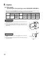
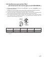
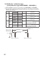
1
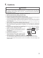
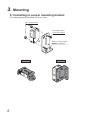
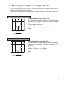
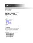
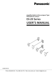
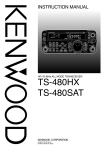
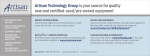
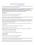
USER’S MANUAL
Power Supply Built-in
Compact Multi-voltage
Photoelectric Sensor
NX-5 Series
WUMJ-NX-5-1
2011.12
panasonic-denkoco.jp/sunx
Contents
1. Cautions ··························································································3
2. Part description ·················································································4
3. Mounting ·························································································6
3-1 Installing to sensor mounting bracket ························································· 6
3-2 Mounting interval (thru-beam type NX5-M□) ················································ 7
3-3 Long sensing range retroreflective type sensor (NX5-RM7□)··························· 9
4. I/O circuit diagram and output operation ··············································· 10
4-1 I/O Circuit Diagram ················································································10
4-2 Output operation ···················································································10
5. Adjustment
5-1 Light axis adjustment (thru-beam type NX5-M10R□ / NX5-M30□)
(retroreflective type NX5-PRVM5□ / NX5-RM7□) ············ 11
5-2 Sensitivity adjustment ············································································12
6. Automatic interference prevention function ··········································· 13
7. Stability indicator ············································································· 14
8. Retroreflective type sensor with polarizing filter (NX5-PRVM5□) ················ 15
9. Option ··························································································· 16
9-1 Slit mask (exclusively for thru-beam type sensor NX5-M10R□ / NX5-M30□) ······ 16
9-2 Interference prevention filter (exclusively for thru-beam type sensor NX5-M10R□) ··17
9-3 Reflector / refractive tape (retroreflective type NX5-PRVM5□ / NX5-RM7□) ·······18
10. Specifications ··············································································· 19
11. Dimensions ·················································································· 21
2
1. Cautions
WARNING
● Never use this product as a sensing device for personnel protection.
● In case of using devices for personnel protection, use products which meet laws and
standards, such as OSHA, ANSI or IEC etc., for personnel protection applicable in
each region or country.
●
●
●
●
●
●
●
●
●
●
This product has been developed / produced for industrial use.
Make sure that the power supply is off while wiring.
Take care that wrong wiring will damage the sensor.
Verify that the supply voltage variation is within the rating.
If power is supplied from a commercial switching regulator, ensure that the frame ground
(F.G.) terminal of the power supply is connected to an actual ground.
In case noise generating equipment (switching regulator, inverter motor, etc.) is used in
the vicinity of this product, connect the frame ground (F.G.) terminal of the equipment to
an actual ground.
Do not run the wires together with high-voltage lines or power lines or put them in the
same raceway. This can cause malfunction due to induction.
Take care that the sensor is not directly exposed to fluorescent lamp from a rapid-starter
lamp, a high frequency lighting device or sunlight etc., as it may affect the sensing performance.
Do not use during the initial transient time (50ms) after the power supply is switched on.
Extension up to total 100m, is possible with
Be sure to
DC relay
connect
0.3mm2, or more, conductor area cable.
a surge
When connecting an inductive load, such as a
Sensor
absorption
DC relay, connect a surge absorber as shown in
COM
diode
the right figure.
+
This sensor is suitable for indoor use only.
Avoid dust, dirt, and steam.
N.O.
Take care that the sensor does not come in direct
N.C.
contact with water, oil, grease, organic solvents,
such as, thinner etc., or strong acid, and alkaline.
The following items are required, as conditions for use in order to conform to CE.
The output applied voltage should be the same as the supply voltage of the sensor.
Be sure to add a short-circuit protection (a fuse or a breaker) to the power supply input
and the output.
Output relay
●
●
●
●
●
3
2. Part description
Thru-beam type emitter: NX5-M10R□
Thru-beam long sensing range type emitter: NX5-M30□
Power indicator (Red)
Lights up when the power is ON
Thru-beam type receiver: NX5-M10R□
Retroreflective type with polarizing filters: NX5-PRVM5□
Diffuse reflective type: NX5-D700□
Sensitivity adjuster
Sensing range becomes
longer by turning clockwise
Stability indicator (Green)
Lights up under the stable
light condition or the
stable dark condition
4
Operation indicator (Red)
Lights up when the
sensing output is ON
Thru-beam long sensing range type receiver: NX5-M30□
Retroreflective long sensing range type: NX5-RM7□
Operation indicator (Red)
Lights up when the
sensing output is ON
Stability indicator (Green)
Lights up under the
stable light condition or
the stable dark condition
5
3. Mounting
3-1 Installing to sensor mounting bracket
The tightening torque should be 0.8 N·m or less.
M4 nuts (Accessory)
M4 (length: 25mm )
screw with washers
Sensor mounting bracket
MS-NX5-1 (Optional)
MS-NX5-2
6
MS-NX5-3
3-2 Mounting interval (thru-beam type NX5-M□)
● In case mounting two sets or more of the this product close together, mount them as
drawing left indicates (typical example)
● Find out the operating point ℓ on the parallel deviation diagram for the setting distance L.
Separate sensors by 2 × ℓ or more.
Sensing distance L (m)
NX5-M10R□ parallel deviation diagram (typical)
10
(L1)
(ℓ1)
5
0
1,000
500
0
500
<Installation interval for NX5-M10R□>
In case using at sensing distance (L1) 10m, the operation point (ℓ1) is approx. 444mm according to diagram
left.
The installation interval is
Approx. 444mm × 2 = 888mm
Thus, install another NX5-M10R□ to 888mm or more
away.
1,000
Right
Left
Center
Operational point ℓ(mm)
NX5-M30□ parallel deviation diagram (typical)
Sensing distance L (m)
40
30
(L2)
20
(ℓ2)
10
0
2,000 1,000
0
<Installation interval for NX5-M30□>
In case using at sensing distance (L2) 30m, the operation point (ℓ2) is approx. 1,200mm according to diagram left.
The installation interval is
Approx. 1,200mm × 2 = 2,400mm
Thus, install another NX5-M30□ to 2,400mm or more
away.
1,000 2,000
Right
Left
Center
Operational point ℓ (mm)
7
L
ℓ
ℓ
Type
NX5-M10R□
NX5-M30□
L
10m
30m
ℓ
Approx. 888mm or more
Approx. 2,400mm or more
● Since retroreflective type NX5-PRVM5□/NX5-RMA□ and diffuse reflective type
NX5-D700A□ incorporate auto interference prevention function, the sensors can mount
closely.
8
3-3 Long sensing range retroreflective type sensor
(NX5-RM7□)
● Please take care of the following points when detecting materials having a gloss
with retroreflective type sensor (NX5-RM7□).
1. Make L, shown in the diagram, sufficiently long. (Note)
2. Install at an angle of 10 to 30 degrees to the sensing object.
Reflector
Glossy surface
Sensing
object
10 to 30°
Sensor
L
The distance L should be as long possible.
Note: In case the distance between the sensor and the sensing object is short, the reflected light from the sensing object may be detected.
● Retroreflective type with polarizing filter (NX5-PRVM5□ )does not need the above
adjustment.
9
4. I/O circuit diagram and output operation
4-1 I/O Circuit diagram
Sensor circuit
Thru-beam type emitter NX5-M10R□/NX5-M30□
Multi-voltage
circuit
Color code
Supply voltage
+10
Brown 24 to 240V AC -15 %
or
+10
Blue
12 to 240V DC -15 %
Internal circuit
Sensor circuit
Thru-beam type receiver NX5-M10R□ / NX5-M30□,
Retroreflective reflective type NX5-PRVM5□ / NX5-RM7□
Diffuse reflective NX5-D700□
Multi-voltage
circuit
Color code
Supply voltage
+10
24
to 240V AC -15 %
Brown
or
+10
Blue
12 to 240V DC -15 %
Output relay
Black ······ N.O.
Gray ······ N.C.
White ······ COM.
Internal circuit
4-2 Output operation
<Output operation>
Type
Output
Output
condition
Power OFF
10
Beamreceived
Beaminterrupted
: Object detected state
Thru-beam & Retroreflective type
Diffuse reflective type
Light-ON (A) type
Dark-ON (B) type
Light-ON (A) type
Dark-ON (B) type
N.O.
N.C.
N.O.
N.C.
N.O.
N.C.
N.O.
N.C.
(Black cable) (Gray cable) (Black cable) (Gray cable) (Black cable) (Gray cable) (Black cable) (Gray cable)
Open
Close
Open
Close
Open
Close
Open
Close
Close
Open
Open
Close
Close
Open
Open
Close
Open
Close
Close
Open
Open
Close
Close
Open
5. Adjustment
5-1 Light axis adjustment
(thru-beam type NX5-M10R□ / NX5-M30□)
(retroreflective type NX5-PRVM5□ / NX5-RM7□)
Thru-beam type NX5-M10R□ / NX5-M30□
1. Place the emitter and the receiver face to face
along a straight line, move the emitter in the up,
down, left and right directions, in order to determine the range of the light received condition with
the help of the operation indicator (red). Then, set
the emitter at the center of this range.
2. Similarly, adjust for up, down, left and right
angular movement of the emitter.
3. Further, perform the angular adjustment for the
receiver also.
4. Check that the stability indicator (green) lights up.
(only for NX5-M10R□)
Sensing object
Emitter
Operation indicator
(Red)
Receiver
Emitter
Stability indicator
(Green)
Receiver
Retroreflective type NX5-PRVM5□ / NX5-RM7□
1. Placing the sensor and the reflector face to face
along a straight line, move the reflector in the up,
down, left and right directions, in order to determine the range of the light received condition with
the help of the operation indicator (red). Then, set
the reflector at the center of this range.
2. Similarly, adjust for up, down, left and right angular movement of the reflector.
3. Further, perform the angular adjustment for the
sensor also.
4. Check that the stability indicator (green) lights up.
(only for NX5-PRVM5□)
Sensing object
Reflector
Operation indicator
(red)
Receiver
Reflector
Stability indicator
(Green)
Receiver
11
5-2 Sensitivity adjustment
Step
1. Turn the sensitivity adjuster fully counterclockwise to the
minimum sensitivity position (MIN.)
Sensitivity
adjuster
MIN. MAX.
2. In sensing object present condition, turn the sensitivity adjuster slowly clockwise and confirm the point A where the
sensor enters the “Light” state operation.
Operation
indicator
(Red)
A
MIN. MAX.
3. In non-sensing object present condition, turn the sensitivity
adjuster further clockwise until the sensor enters the “Light”
state operation and then bring it back to confirm point B
where the sensor just returns to the “Dark” state operation.
If the sensor does not enter the “Light” state operation
even when the sensitivity adjuster is turned fully clockwise, the position is point B.
4. The position at the middle of points A and B is the optimum
sensing position.
A
B
MIN. MAX.
Optimum
position
A
B
MIN. MAX.
Note: Use the accessory adjusting screwdriver to turn the adjuster slowly. Turning with excessive strength will cause
damage to the adjuster.
12
6. Automatic interference prevention function
● The retroreflective type NX5-PRVM5□ / NX5-RM7□ and the diffuse reflective type
NX5-D700□ incorporate an automatic interference prevention function, so that two sensors can be mounted closely. (Thru-beam type NX5-M10R / NX5-M30□ does not incorporate the automatic interference prevention function.)
Note: If NX5-D700□ are mounted facing each other, they should be angled so as not to receive the beam from
the opposing sensor or to detect its front face.
Not good
Good
13
7. Stability indicator
● The stability indicator (green) lights up when the incident light intensity has sufficient
margin with respect to the operation level.
Incident light intensity level is such that the stability indicator light up, stable sensing can
be done without the light received operation and the light interrupted operation being
affected by a change in ambient temperature or supply voltage.
Use the staility indicator in the condition below
• Adjusting the light axes
• Checking dirt of the sensor
14
8. Retroreflective type sensor with
polarizing filter (NX5-PRVM5□)
If a shiny object is covered or wrapped with a transparent film, such as those described
below, the retroreflective type sensor with polarizing filters NX5-PRVM5□ may not be
able to detect it. In that case, take the following measures given below.
<Example of sensing objects>
• Can wrapped by clear film
• Aluminum sheet covered by plastic film
• Gold or silver color (specular) label or wrapping paper
<Measures>
• Tilt the sensor with respect to the sensing object while fitting.
• Reduce the sensitivity.
• Increase the distance between the sensor and the sensing object.
15
9. Option
9-1 Slit mask
(exclusively for thru-beam type sensor NX5-M10R□/NX5-M30□)
With the slit mask OS-NX5-3×6, the sensor can detect an object as small as 3 × 6mm.
However, the sensing range is reduced when the slit mask is mounted.
Model No.
Type
Slit mask
Slit mask
Exclusively
OS-NX5-3×6
for thrubeam type
Sensor
Sensing distance
Min. sensing object
Slit mask
Mounting
Mounting
Mounting
Mounting
size
on one side on both side on one side on both side
NX5-M10R□
3m
1m
φ10mm
3 × 6mm
16m
6m
φ20mm
3 × 6mm
3 × 6mm
NX5-M30□
Mounting method
1. Fit the C portion of the slit mask in the groove A of the
main body case.
2. Then press the slit mask against the main body to fit
the slit mask hook D portion in the groove B of the main
body case.
Groove B
D
2
1
C
Groove A
1
Removing method
1. Insert a flat head driver into the E portion of the slit
mask.
2. Lift the E portion up to remove the slit mask from the
main body case.
16
Slit mask
2
E
9-2 Interference prevention filter
(exclusively for thru-beam type sensor NX5-M10R□)
● By mounting interference prevention filters PF-NX5-□, two sets of NX5-M10R□ can be
mounted close together.
However, the sensing range is reduced when the interference prevention is mounted.
● The filters can be mounted by the same method as for the slit masks.
● There are two types of interference prevention filters. The two sets of thru-beam type
sensors should be fitted with different types of interference prevention filters.
● The interference prevention does not work even if the filters are mounted for emitters
only, receivers only or the same model No. of the interference prevention filters are
mounted on both the sets of the sensor.
Fitted with
PF-NX5-H
Fitted with
PF-NX5-V
Model No.
Direction of
thru-beam axis
Color of the bracket
Sensing distance
Min. sensing object
PF-NX5-V
Vertical
Silver
5m
ø20mm
PF-NX5-H
Horizontal
Light brown
5m
ø20mm
Note: The model No. is not shown on the interference prevention filters. Take care when mounting them on the
sensors.
17
9-3 Reflector / reflective tape
(retroreflective type NX5-PRVM5□ / NX5-RM7□)
● Reflector RF-230 is accessory of retroreflective type NX5-PRVM5□ and NX5-RM7□.
● By using reflector (optional) or reflectivity tape (optional), small object can be detected.
However, the sensing distance would be shorter by using reflector (optional) or
reflectivity tape (optional).
Model No.
Sensor
Designation
RF-230
(Accessory)
Sensing
distance
NX5-PRVM5□
0.1 to 5m
NX5-RM7□
0.1 to 7m
Reflec- RF-210
tor
(Optional)
NX5-PRVM5□
0.1 to 1.5m
NX5-RM7□
0.1 to 2.5m
RF-220
(Optional)
NX5-PRVM5□
0.1 to 3.5m
Reflective
tape
RF-11
(Optional)
RF-12
(Optional)
NX5-RM7□
Specification
ø50mm
Dimension (W × H × D):
50.3mm × 59.3mm × 8.3mm
Thru-hole threads: ø3.7mm
ø30mm
Dimension (W × H × D):
33.3mm × 12.8mm × 11mm
Thru-hole threads: ø3.4mm
ø35mm
Dimension (W × H × D):
35.3mm × 42.3mm × 8.3mm
Thru-hole threads: ø3.6mm
ø30mm
Dimension (W × H × D):
30mm×8mm×0.7mm
Ambient temperature: -25 to +50ºC
Ambient humidity: 35 to 85%RH
ø30mm
Dimension (W × H × D):
30mm × 25mm × 0.7mm
Ambient temperature: -25 to +50ºC
Ambient humidity: 35 to 85%RH
0.1 to 5m
NX5-PRVM5□
0.1 to 0.8m
NX5-RM7□
0.1 to 1m
NX5-PRVM5□
0.1 to 1m
NX5-RM7□
Min. sensing object
0.1 to 1.5m
In case of RF-230
Reflector cannot be
placed in this range.
0.1m
Sensor
Setting range of reflector /
reflective tape
Reflector / reflective tape
18
5m (NX5-RM7□ is 7m)
Actual sensing range
of the sensor
Reflector / reflective tape
10. Specification
Thru-beam
Type
Retroreflective
Diffuse reflective
Long sensing
range
With polarizing
filters (Note 2)
Long sensing range
NX5-M10RA
NX5-M30A
NX5-PRVM5A
NX5-RM7A
NX5-D700A
NX5-M10RB
NX5-M30B
NX5-PRVM5B
NX5-RM7B
NX5-D700B
Sensing range
10m
30m
0.1 to 5m (Note 3)
0.1 to 7m (Note 3)
700mm (Note 4)
Sensing object
Opaque object of
ø20mm or more
(Note 5)
Opaque object of
ø20mm or more
Completely beam
interrupted object
(Note 5)
ø50mm, Opaque,
translucent or
specular objects
(Note 3, 6)
ø50mm, Opaque,
translucent or
objects
(Note 3, 6)
Opaque, translucent or transparent
object
(Note 6)
Model
Light-ON
No.
(Note 1) Dark-ON
Hysteresis
Repeatability
perpendicular to
sensing axis
0.1 mm or less
0.2 mm or less
Supply voltage
Power consumption
Output
24 to 240V AC
% or 12 to 240V DC
2VA or less
Relay contact 1c
• Switching capacity: 250V AC 1A (resistive load)
30V DC 2A (resistive load)
• Electrical life: 100,000 or more operations (at AC rated load and switching 3,600 operations/hour)
500,000 or more operations (at AC rated load and switching 3,600 operations/hour)
• Mechanical life: 100,000,000 or more operations (switching 36,000 operations/hour)
10ms or less
Sensitivity adjuster
Variable adjuster
-
Automatic interference prevention
function
- (Note 7)
-
Variable adjuster
-
Variable adjuster
Incorporated
(Two units of sensors can be mounted closely.)
Protection
IP66 (IEC)
−25 to +55 °C (No dew condensation or icing allowed), Storage: −30 to +70 °C
Ambient humidity
Emitting element
0.3 mm or less
% Ripple P-P10% or less
Emitter: 1VA or less Emitter: 1.5VA or less
Receiver: 2VA or less Receiver: 2VA or less
Response time
Ambient
temperature
15% or less of
operation distance
(Note 4)
-
35 to 85% RH, Storage: 35 to 85 %RH
Red LED
Infrared LED
Red LED
Infrared LED
Material
Enclosure: Polycarbonate, Lens: Polycarbonate, Cover: Polycarbonate
Front cover: Acrylic (retroreflective type sensor only)
Cable
0.3 mm2 5-core (thru-beam type emitter: 2-core) cabtyre cable, 2m long
Weight
Emitter: approx. 100g Emitter: approx. 125g
Receiver: approx. 140g Receiver: approx. 40g
Accessories
Adjusting screwdriver:
1 pc.
-
Approx. 140g
RF-230 (Reflector):
1 pc. RF-230 (Reflector): Adjusting screwdriver:
Adjusting screwdriver:
1 pc.
1 pc.
1 pc.
19
Notes: 1) The model No. with suffix “P” shown on the label affixed to the thru-beam type sensor is the emitter, “D”
shown on the label is the receiver.
(e.g.) Thru-beam type sensor emitter: NX5-M10RP, Thru-beam type sensor receiver: NX5-M10RAD
2) The retroreflective type sensor with polarizing filters may not stably detect specular or glossy objects
through transparent film since light is polarized by the transparent film.
3) The sensing range and sensing object for the retroreflective type sensor is specified for the RF-230 reflector. Further, the sensing range is the possible setting range for the reflector. The sensor can detect
an object less than 0.1m away.
Reflector cannot be
placed in this range.
Sensor
Actual sensing
range of the sensor
0.1m Setting range of
5m NX5-RM7□
is 7m
the reflector
Reflector
Reflector
4) The sensing range and hysteresis of the diffuse reflective type sensor and narrow-view reflective type
sensor are specified for white non-glossy paper (200 × 200mm) as the object.
5) If slit masks (optional) are fitted, an object as small as 3 × 6mm can be detected.
6) Make sure to confirm detection with an actual sensor before use.
7) By mounting optional interference prevention filter PF-NX5-□, two sensors can be mounted closely.
8) In case the sensor is to be used at an ambient temperature of -15°C or less, please contact our office.
20
11. Dimensions
Thru-beam type emitter: NX5-M10R□, Thru-beam long sensing range type: NX5-M30□
(Unit: mm)
18
35
6
20
50
62
Beam axis
2-ø4.5 mounting holes
2-M4 nut seats (on both sides)
4
5
25
ø5.8 cable, 2m long
Thru-beam type receiver: NX5-M10□
(Unit: mm)
18
35
6
20
Beam axis
50
62
2-ø4.5 mounting holes
2-M4 nut seats (on both sides)
4
5
25
ø5.8 cable, 2m long
21
Retroreflective with polarizing filters type: NX5-PRVM5□,
Diffuse reflective type: NX5-D700□
(Unit: mm)
18
35
Beamreceiving part
6
20.5
Beamemitting part 62
Center of
sensing
50
2-ø4.5 mounting holes
2-M4 nut seats (on both sides)
4
5
25
ø5.8 cable, 2m long
Retroreflective long sensing range type: NX5-RM7□
(Unit: mm)
18
35
Beamreceiving part
6
20.5
Center of
sensing
Beamemitting part
50
62
2-ø4.5 mounting holes
2-M4 nut seats (on both sides)
4
5
22
25
ø5.8 cable, 2m long
Reflector: RF-230
(Unit: mm)
50.3
49.3
59.3
(30)
10
5
3.3
40
8.3
2-ø4.6 mounting holes
Reflector: RF-220
(Unit: mm)
35.3
42.3
34.3
(30)
8
5
25
3.3
8.3
2-ø3.6 mounting holes
23
Reflector: RF-210
(Unit: mm)
33.3
12.8
2-M3 nut inserting hole
(For backside mounting)
11
2-ø3.4 through-hole
(For side mounting)
3.2
25
10
2-ø3.4 hole depth 6
(For backside mounting)
2-M3 nut inserting hole
(For side mounting)
Reflective tape: RF-11
(Unit: mm)
30
(28)
8 (6)
0.7
Adhesive tape
Reflective tape: RF-12
(Unit: mm)
30
(28)
0.7
25 (23)
Adhesive tape
24
(MEMO)
25
Please contact ..........
Panasonic Electric Works SUNX Co., Ltd.
■ Overseas Sales Division (Head Office): 2431-1 Ushiyama-cho, Kasugai-shi, Aichi, 486-0901, Japan
■ Telephone: +81-568-33-7861 ■ Facsimile: +81-568-33-8591
panasonic-electric-works.net/sunx
Europe Headquarter: Panasonic Electric Works Europe AG
■ Head Office: Rudolf-Diesel-Ring 2, D-83607 Holzkirchen, Germany
■ Telephone: +49-8024-648-0
US Headquarter: Panasonic Electric Works Corporation of America
■ Head Office: 629 Central Avenue New Providence, New Jersey 07974 USA
■ Telephone: +1-908-464-3550
© Panasonic Electric Works SUNX Co., Ltd. 2011
WUME-NX5-1