1
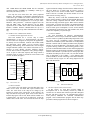
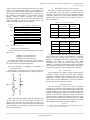
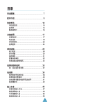
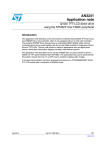
(IJACSA) International Journal of Advanced Computer Science and Applications,
Vol. 6, No. 6, 2015
Intelligent Wireless Indoor Monitoring System based
on ARM
Jia Chunying
Zhang Liping*
Chen Yuchen
School of Electronic and Electrical
Engineering
Shanghai University of Engineering
Science, SUES
Shanghai, China
School of Electronic and Electrical
Engineering
Shanghai University of Engineering
Science, SUES
Shanghai, China
School of Electronic and Electrical
Engineering
Shanghai University of Engineering
Science, SUES
Shanghai, China
Abstract—This paper proposed an intelligent wireless indoor
monitoring system based on STM32F103. The system
compromises a master and terminals, which communicates
through a CC1101 433M wireless unit. Using ENC28J60 and
SIM900A to access Ethernet, the system can intelligent push
information to cloud server, therefore we can observe and
control terminals remotely. This paper present an algorithm
based on MCU ID for terminal code recognition. The algorithm
can intelligently discriminate terminals through code matching
code between master and terminals, though hardware and
software of terminals is similar. The experiment demonstrates
that the proposed system is robust stability, real-time and obtains
accurate warning information.
RFID
433M Wireless
External
Interrupt
SPI2
GPIO
USART1
MCU
SPI1
With the rapid development of China's network technology,
information technology/economy, people's requirements of the
life quality increase gradually. In such a high-paced living
environment, traditional indoor video surveillance systems
appear to be inadequate. Intelligent interior monitoring system
uses the cloud server, which can real-time detect indoor state
when an exception occurs, automatically alarm and timely send
the warning to user. Therefore, it can greatly reduce the family
security risks.
In this paper, an intelligent system based on STM32F103 is
designed to predict household hazards, and send the indoor gas
concentrations and smoke density information, situation of
indoor power, emergency data to the monitoring center through
both wired and wireless network.
USART3
Ethernet
GPRS/GSM
Twisted Pair
Fig. 2. monitoring host
Host Communicate with the terminal through a 433M
wireless module. Normally the host uses a query method to get
terminal operating status. The monitoring terminal sends alarm
information to the host immediately if an abnormal condition is
detected. The host sends the information to the cloud server
through wired Ethernet or GPRS / GSM. The server pushes
messages to user’s phone, to achieve the purpose of real-time
monitoring.
III.
Host
Terminal
Fig. 1. Monitoring system proposed
WIFI
USART2
INTRODUCTION
Cloud server
MONITORING HOST
As shown in Figure 2, the Monitoring host contains a 433M
wireless communication unit, a WIFI and a RFID module, an
Ethernet and a GPRS / GSM module.
MX232
I.
II.
PC
Keywords—STM32; CC1101; Intelligent Monitoring; ID;
Corresponding Code Discrimination
As shown in Figure 1, the system consists of a host and
terminals, which communicates each other through 433M
wireless units.
HARDWARE
A. Cortex-M3 STM32F103VET6
We used a STM32F103VET6 MCU as the system’s core,
which is produced by ST Microelectronics. STM32F103VET6
is based on ultra-low-power ARM Cortex-M3 processor core.
The STM32F103VET6 series are a powerful lineup in 32 bit
STM32 microcontroller family. They have good compatibility.
ARM Cortex-M3 core set is specialized in high-efficiency lowenergy in real-time applications. It has high cost-effective
which embedded developers favor so much. The enhanced chip
27 | P a g e
www.ijacsa.thesai.org
(IJACSA) International Journal of Advanced Computer Science and Applications,
Vol. 6, No. 6, 2015
with 512KB RAM and 64KB SRAM has the maximum
operating frequency of72MHz, up 1.25DMips / MHz [1] at
zero wait cycle memory access.
The chip has more than three SPI (serial peripheral
interface). The full duplex or half-duplex communication rate
of SPI can be up to 18 Mbit /sec in slave or master mode. It has
a 3 bit prescaler which produces eight kinds of master mode.
Its frequencies can be configured as 8 or 16 bits per frame.
Hardware CRC generation / verification supports basic SD
card and MMC mode. All SPI interfaces can use DMA
operations. It has 3 UART and 2 UART serial communication
interface, USART1 interface communication rate up to 4.5
Mbit / sec interface speed up other communication 2.25 Mbit /
s[1].
B. 433M wireless communication module
1) Introduction and Application CC1101
Host and terminal use a CC1101 chip to realize
communication. CC1101 is a high-performance sub-1GHz
wireless transceiver designed for low-power RF applications.
It’s mainly used for industrial, scientific and medical (ISM)
and short-range device (SRD). CC1101 provides packet
handling, data buffering, burst transmissions, received signal
strength indication (RSSI), clear channel assessment (CCA),
Wireless on wake (WOR), extensive hardware support.
CC1101 and CC1100 are compatible in code, package and pinout. It is open to sub-1GHz frequency RF design which is
commonly used in world [2]. Interfaces between MCU and
CC1101 are shown in Figure 3.
VCC
MCU
CC1101
PB15/MOSI
SCLK
PB14/MISO
When they need to send data, STM32F103ZET6 writes
data to wireless module at a lower rate through SPI. RF circuits
start after writing completed while RF circuits send written
data out and empty TX-FIFO register. When wireless module
received data, it sent the received data is to STM32F103ZET6
through the SPI. Because the wireless module can enter sleep
mode to reduce power consumption, CC1101 wireless module
can automatically generate the CRC and preamble code, which
reduces the complexity of system design.
3) Ethernet Module
We used ENC28J60 for Ethernet communication.
ENC28J60 is the first 28-pin stand-alone Ethernet controller
over the world. It is produced by Microchip and provides a low
pin count, low-cost, streamlined remote communications
solutions for embedded systems. ENC28J60 is an independent
Ethernet controller with an industry-standard serial peripheral
interface. It meets all IEEE 802.3 specification, using a series
of packet filtering schemes to limit incoming packets. It also
provides an internal DMA module for fast data throughput and
hardware support for IP checksum calculation. Communication
with the host controller is provided by two interrupt pin (INT
and WOL) and SPI pins (SO, SI, SCK, CS). The data transfer
rates of ENC28J60 is up to 10Mb / s. Two dedicated pins
(LEDA, LEDB) is used for connecting a LED which indicators
the network activity. Figure 4 is the wiring diagram for the
MCU with ENC28J60.
MCU
SI
PB13/SCK
registers and mode settings when the wireless module enters an
idle state. When we set inside STX bit register, crystal is
startup, and CC1101 wireless module enters a transmission
mode. If the bit is set SRX, the wireless module of CC1101
enters into the receiving state [3].
SO(GDO1)
ENC28J60
PA7/MOSI
SI
PA5/SCK
SCK
PD8
GDO2
PA6/MISO
PD9
GDO0
PD10
PB12/NSS
TX/RX
SO
INTn Buffer
WOLn
MAC
PHY
CSn
PA4/NSS
CSn
GND
Fig. 4. ENC28J60 and MCU circuit
Fig. 3. MCU and CC1101
2) Wireless module
CC1101 have five work modes, part of the idle mode, sleep
mode, receive mode, sent mode and crystal oscillator close
mode. The work mode of the chip can be change by the
internal set register of the external pin. At first electrify, the
chip will enter the sleep mode, pause work, but the value of
internal chip register can’t be lost. When wireless module is in
a dormant state, you can pin CSn is pulled low, so that the
module enters an idle state. You can read and write the chip
IV.
SOFTWARE SYSTEM
A. The host software and system structure
In this system, we used Keil uVision5 MDK as
development tool. It was officially released by ARM on
October 2013. It includes data collection procedures Wiegand
ID card, SPI driver, and TCP / IP communication protocol
LwIP protocol, SIM900A AT command communication
program, serial communication program and the main loop
procedures. Master program flow is shown in Figure 5.
28 | P a g e
www.ijacsa.thesai.org
(IJACSA) International Journal of Advanced Computer Science and Applications,
Vol. 6, No. 6, 2015
basis of ECC is rational points on an elliptic curve additive
group constituting the Abel elliptic discrete logarithm
computational difficulty.
Start
Initialization
Compared with classic RSA, DSA, and other public key
cryptosystem, elliptic cryptosystem has high security,
processing speed, small storage space, and low bandwidth
requirements. Some studies indicate that elliptical key 160 and
1024 has the same RSA key security. On the private key
encryption and decryption, ECC algorithm has a faster speed
than RSA, DSA. Elliptic Curves Cryptography flow is shown
in Figure 7.
Get_ID
Power_Check
Button
On
Match
Code
Off
Input wP
ID_Card_Check
Put integer w express
as binary system
w=(ak-1, ,a1,a0)
Node_Data_Check
i=k-1
Fig. 5. Figure 5 flowchart
The main program is mainly responsible for components
initialization. In software systems, Because of the control parts
is fewer, we do not use the operating system. The matching
code switch is used to discriminate the same set of
identification for communication between devices.
ak=1
N
Q=Q+P
B. Communication between the host and terminal
Y
1) The Communication Protocol
In this design, the communication between host and
terminal uses a 433M wireless module, which has strength
signal, high anti-jamming etc. The communication included
request, response, and transmission, closed four states. The
switch of communicate state is shown in Figure 6.
Host
Q=2*Q
i=i-1
i>0
Terminal
Output wP
Fig. 7. Flow chart of Elliptic Curves Cryptography
Request
3) The match code identification solutions based on MCU
ID
Response
Since the terminal can freely expand, there will have an
identical terminal device. The host cannot identify the terminal
which sends information it received. To solve the problem, we
propose a solution to identifying terminal by MCU ID Code.
Data transmission
Transmission
Fig. 6. Communication state transition
a) Electronic Signature
Electronic signature stored in the system memory area of
the flash memory module, you can use JTAG/SWD or CPU to
read. Chip identification information contains writing at the
factory. User firmware or external device can read an
electronic signature, to automatically match the different
configurations SRM32F10xxx microcontroller.
2) Encryption Algorithm
In order to ensure secure communications, the design uses a
lightweight ECC encryption algorithm. Elliptic Curves
Cryptography (ECC) is a public key encryption system, which
is proposed in 1985 by Koblitz and Miller. The mathematical
b) MCU 96 bit unique identity ID
A 96 bit of unique identity is provided to any one of the
STM32 microcontroller. Users under any circumstances cannot
change this identity. The 96 bit unique identity of the product,
according to the usage of different users, can be read in bytes
Close
29 | P a g e
www.ijacsa.thesai.org
(IJACSA) International Journal of Advanced Computer Science and Applications,
Vol. 6, No. 6, 2015
(8 bit) as a unit, or can be read in half-word (16 bit) or wholeword (32 bit). Product unique identity is very suitable to be
used as 1) A sequence number (such as USB serial numbers or
other characters in the terminal application) 2) A password in
the preparation of flash memory; 3) In conjunction with this
uniquely identifies software encryption and decryption
algorithms to improve code safety in the flash memory; 4)
Safety mechanism to activate the bootstrap process. The
structure of the ID storage is shown in Figure 8.
Address
Offset
0x00
0x02
V.
We selected a 4 rooms and 2 hall area of 128 square meters
for experimental. A host was placed in a drawing room, and
terminals were placed in cook room (gas monitor), bathroom
(emergency button), study room (smog monitoring), master
bedroom (bed vacancy monitor). Test results are shown in
Table 1 and Table 2.
TABLE I.
8 7 6
U_ID[15:0]
5
4
3
2
1
0
15 14 13 12 11 10 9 8 7 6 5
U_ID[31:16]
4
3
2
1
0
15 14 13 12 11 10 9 8 7 6 5
U_ID[47:32]
4
3
2
1
15 14 13 12 11 10 9 8 7 6 5
U_ID[79:64]
4
3
2
1
326ms
3.2s
Bathroom
216ms
2.1s
Study room
302ms
1.3s
Bedroom
416ms
3.2s
0
TABLE II.
Fig. 8. ID Code Storage Structure
c) Reads and encrypted ID code
Use the following code in the main program can read the
MCU 96 ID.
ID_Code=(CpuID[0]>>1)+(CpuID[1]>>2)+(CpuID[2]>>3;
d) Matching Code
In this paper, for security reasons, we uses a match code
switch in hardware. The hardware circuit is shown in Figure 9.
ETHERNET IS DISCONNECTED
Monitoring host
Response delay
0
CpuID[0]=*(vu32*)(0x1ffff7e8);
CpuID[1]=*(vu32*)(0x1ffff7ec);
CpuID[2]=*(vu32*)(0x1ffff7f0);
Considering the practical use does not need to 96 bit, as
well as security using simple encryption algorithm compresses
96 to 24-bit codes, the encryption algorithm is;
Server
response delay
Cook room
31 30 29 28 27 26 25 24 23 22 21 20 19 18 17 16
U_ID[95:80]
0x08
ETHERNET IS CONNECTED
Monitoring host
Response delay
Base address:0x1FFF F7E8
15 14 13 12 11 10 9
31 30 29 28 27 26 25 24 23 22 21 20 19 18 17 16
U_ID[63:48]
0x04
EXPERIMENTAL RESULTS AND ANALYSIS
Server
response delay
Cook room
413ms
10.6s
Bathroom
321ms
11.3s
Study room
215ms
10.7s
Bedroom
258ms
12.5s
As shown in Table 1 and Table 2, it can be seen that he
server response time is about 2.5s when Ethernet is connected,
whereas the server response time is about 12s when the
Ethernet is disconnected. Because this phenomenon is that
SIM900A uses GPRS to communicate while GPRS
transmission rate is only about 56 to 114Kbps . However,
10Mbps is a certain gap for ENC28J60. System design taking
into consideration factors such as cost and stable areas, there is
no choice of the current 3G/4G communications technology.
VI.
CONCLUSION
The experiments show that the control system design is
reasonable, reliable operation and has good scalability
comparing to traditional video surveillance system. The alarm
information is accurate, targeted and real-time. The system
pushes cloud exception information to cloud server which is
used remotely observe and control terminals.
ACKNOWLEDGMENT
Fig. 9. code switching circuit
KEY1 is the match code button. When the button is pressed
for more than 2s, it will start the program of match code.
Master sends and saves ID Code, while the success of
matching code is returned. As the matching code indicator light,
LED1 will flash 5 times in frequency of twice per second after
success of matching code.
First and foremost, I would like to show my deepest
gratitude to my supervisor, Prof. Zhang Liping, a respectable,
responsible and resourceful scholar, who has provided me with
valuable guidance in every stage of the writing of this paper.
Without her enlightening instruction, impressive kindness and
patience, I could not have completed my paper. Her keen and
vigorous academic observation enlightens me not only in this
paper but also in my future study. I would also like to thanks
my teacher Prof. Chen Yuchen he have helped me to develop
the fundamental and essential academic competence.
[1]
REFERENCES
STMicroelectronics.STM32Reference annual (RM0008). http:// www.
stm. com . 2012,16-18,69,70,422,472.
30 | P a g e
www.ijacsa.thesai.org
(IJACSA) International Journal of Advanced Computer Science and Applications,
Vol. 6, No. 6, 2015
[2]
[3]
[4]
[5]
[6]
[7]
[8]
Texas Instruments.CC1101 user’s manual[EB/OL].2008.http://focus.ti.
Com/lit/ds/symlink1/c 101. pdf.
Nan Yimin. Based STM32F103xxx peripheral device programming
STM32 standard peripheral libraries [J]. Journal of Changsha
Aeronautical Vocational and Technical College. 2010(04),41-45
CC1101 Single-Chip Low Cost Low Power RF-Transceiver, Data
Sheet [Z],Texas Instruments,2008.
WIFI chip of low-power specification ESP8266.[s] 2013.12 5,6
Hosam El-Ocla. TCP CERL: congestion control enhancement over
wireless networks[J]. Wireless Networks , 2010, 16(1):183-198
Wang Mingxin.
GSM Remote Monitoring System Based on
SIM900A[J]. Journal of computer knowledge and technology.
2014(15):3500-3504.
Wang Lei, Wang Jun. Embedded remote appliance controller design
Based on SIM900A[J].2014,27(1):76-80.
[9]
[10]
[11]
[12]
[13]
lwIP--A Lightweight TCP/IP stack[ EB / OL]. http://savannah.nongnu.
org /projects/lwip/ .
Han Zexi, Lv Fei. Research and development of GSM network AT
command emulation system [J]. Modern electronic technology.
2005,28(17):9-11.
Bi Dandan, Li Yun, Feng Zhi. Smart car design based on MCU and
GSM modules [J]. Data communication. 2014,(04):41-43
Wei Hongtao, Wong Huijuan, Wu Xixiu. The Design and
implementation of emergency communication control system Based on
3G[J]. Journal of Wuhan University of Technology Information &
Management Engineering. 2014,36(04):443-446.
Que Fanbo. The Design of program Remote upgrade Based on STM32.
[J]. Electronic Instrumentation Customer. 2013(05),90-92
31 | P a g e
www.ijacsa.thesai.org