1
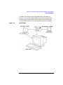
Managing Systems and Workgroups:
A Guide for HP-UX System
Administrators
HP 9000 Computers
Edition 5
Manufacturing Part Number: B2355-90742
E0601
United States
© Copyright 1983-2001 Hewlett-Packard Company. All rights reserved.
Legal Notices
The information in this document is subject to change without notice.
Hewlett-Packard makes no warranty of any kind with regard to this
manual, including, but not limited to, the implied warranties of
merchantability and fitness for a particular purpose. Hewlett-Packard
shall not be held liable for errors contained herein or direct, indirect,
special, incidental or consequential damages in connection with the
furnishing, performance, or use of this material.
Warranty
A copy of the specific warranty terms applicable to your Hewlett-Packard
product and replacement parts can be obtained from your local Sales and
Service Office.
Restricted Rights Legend
Use, duplication or disclosure by the U.S. Government is subject to
restrictions as set forth in subparagraph (c) (1) (ii) of the Rights in
Technical Data and Computer Software clause at DFARS 252.227-7013
for DOD agencies, and subparagraphs (c) (1) and (c) (2) of the
Commercial Computer Software Restricted Rights clause at FAR
52.227-19 for other agencies.
HEWLETT-PACKARD COMPANY
3000 Hanover Street
Palo Alto, California 94304 U.S.A.
Use of this manual and flexible disk(s) or tape cartridge(s) supplied for
this pack is restricted to this product only. Additional copies of the
programs may be made for security and back-up purposes only. Resale of
the programs, in their present form or with alterations, is expressly
prohibited.
Copyright Notices
Copyright 1983-2001 Hewlett-Packard Company. All rights reserved.
Reproduction, adaptation, or translation of this document without prior
written permission is prohibited, except as allowed under the copyright
laws.
2
Copyright 1979, 1980, 1983, 1985-93 Regents of the University of
California. This software is based in part on the Fourth Berkeley
Software Distribution under license from the Regents of the University
of California.
Copyright 1988 Carnegie Mellon University
Copyright 1990-1995 Cornell University
Copyright 1986 Digital Equipment Corporation.
Copyright 1997 Isogon Corporation
Copyright 1985, 1986, 1988 Massachusetts Institute of Technology.
Copyright 1991-1997 Mentat, Inc.
Copyright 1996 Morning Star Technologies, Inc.
Copyright 1990 Motorola, Inc.
Copyright 1980, 1984, 1986 Novell, Inc.
Copyright 1989-1993 The Open Software Foundation, Inc.
Copyright 1996 Progressive Systems, Inc.
Copyright 1989-1991 The University of Maryland
Copyright 1986-1992 Sun Microsystems, Inc.
Trademark Notices
Apple and Macintosh are trademarks of Apple Computer, Inc.,
registered in the United States and other countries.
AppleShare is a registered trademark of Apple Computer, Inc.
CHAMELEON is a trademark of NetManage, Inc.
DIGITAL and PATHWORKS are trademarks of Digital Equipment
Corporation.
DiskAccess is a registered trademark of Intergraph.
EXCURSION is a trademark of Digital Equipment Corporation.
Exeed is a registered trademark of Hummingbird Communications
Ltd.
eXodus is a trademark of White Pine Software, Inc.
MS-DOS and Microsoft are U.S. registered trademarks of Microsoft
Corporation.
NTRIGUE is a trademark of Insignia Solutions, Inc.
OSF/Motif is a trademark of the Open Software Foundation, Inc. in the
U.S. and other countries.
3
PC_Xware is a trademark, and WinCenter is a registered trademark
of Network Computing Devices, Inc.
REFLECTION and WRQ are registered trademarks of WRQ, Inc.
UNIX is a registered trademark in the United States and other
countries, licensed exclusively through The Open Group.
VERITAS is a registered trademark of VERITAS Software
Corporation.
VERITAS File System is a trademark of VERITAS Software
Corporation.
WinDD is a trademark of Tektronix, Inc.
X Window System is a trademark of the Massachusetts Institute of
Technology.
4
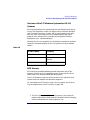
Publication History
The manual publication date and part number indicate its current
edition. The publication date will change when a new edition is released.
The manual part number will change when extensive changes are made.
To ensure that you receive the new editions, you should subscribe to the
appropriate product support service. See your HP sales representative
for details.
• First Edition: October 1997, B2355-90157, (HP-UX 11.0),
Printed, CD-ROM (Instant Information), and Web
(http://www.docs.hp.com/)
• Second Edition: May 1998, B2355-90664, (HP-UX 11.0),
CD-ROM and Web (Printed version available from
http://www.fatbrain.com/)
• Third Edition: February 2000,
CD-ROM and Web
B2355-90676,
(HP-UX 11.0)
• Fourth Edition: October 2000, B2355-90701, (HP-UX 11i),
Printed, CD-ROM (Instant Information), and Web
(http://www.docs.hp.com/)
• Fifth Edition: June 2001, B2355-90742, (HP-UX 11i),
Printed, CD-ROM (Instant Information), and Web
(http://www.docs.hp.com/)
5
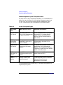
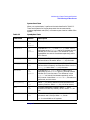
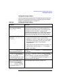
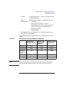
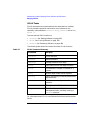
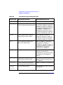
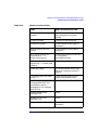
Conventions
We use the following typographical conventions.
audit (5)
An HP-UX manpage. audit is the name and 5 is the
section in the HP-UX Reference. On the web and on the
Instant Information CD, it may be a hot link to the
manpage itself. From the HP-UX command line, you
can enter “man audit” or “man 5 audit” to view the
manpage. See man (1).
Book Title
The title of a book. On the web and on the Instant
Information CD, it may be a hot link to the book itself.
KeyCap
The name of a keyboard key. Note that Return and Enter
both refer to the same key.
Emphasis
Text that is emphasized.
Emphasis
Text that is strongly emphasized.
Term
The defined use of an important word or phrase.
ComputerOut
Text displayed by the computer.
UserInput
Commands and other text that you type.
Command
A command name or qualified command phrase.
Variable
The name of a variable that you may replace in a
command or function or information in a display that
represents several possible values.
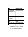
[ ]
The contents are optional in formats and command
descriptions.
{ }
The contents are required in formats and command
descriptions. If the contents are a list separated by |,
you must choose one of the items
...
The preceding element may be repeated an arbitrary
number of times.
|
Separates litems in a list of choices.
6
Contents
1. Systems and Workgroups
Workgroup Focus . . . . . . . . . . . . . . . . . . . . . . . . . . . . . . . . . . . . . . . . . . . . . . . . . . . . . . .
How We Are Using the Terms “System” and “Workgroup” . . . . . . . . . . . . . . . . . . . . . .
System . . . . . . . . . . . . . . . . . . . . . . . . . . . . . . . . . . . . . . . . . . . . . . . . . . . . . . . . . . . . . .
Workgroup . . . . . . . . . . . . . . . . . . . . . . . . . . . . . . . . . . . . . . . . . . . . . . . . . . . . . . . . . . .
Types of System . . . . . . . . . . . . . . . . . . . . . . . . . . . . . . . . . . . . . . . . . . . . . . . . . . . . . . . .
Single-User versus Multiuser . . . . . . . . . . . . . . . . . . . . . . . . . . . . . . . . . . . . . . . . . . .
Server versus Client . . . . . . . . . . . . . . . . . . . . . . . . . . . . . . . . . . . . . . . . . . . . . . . . . . .
Hardware. . . . . . . . . . . . . . . . . . . . . . . . . . . . . . . . . . . . . . . . . . . . . . . . . . . . . . . . . . . .
Operating Systems . . . . . . . . . . . . . . . . . . . . . . . . . . . . . . . . . . . . . . . . . . . . . . . . . . . .
Types of Workgroup . . . . . . . . . . . . . . . . . . . . . . . . . . . . . . . . . . . . . . . . . . . . . . . . . . . . .
NFS Diskless. . . . . . . . . . . . . . . . . . . . . . . . . . . . . . . . . . . . . . . . . . . . . . . . . . . . . . . . .
Multiuser . . . . . . . . . . . . . . . . . . . . . . . . . . . . . . . . . . . . . . . . . . . . . . . . . . . . . . . . . . . .
Client-Server . . . . . . . . . . . . . . . . . . . . . . . . . . . . . . . . . . . . . . . . . . . . . . . . . . . . . . . . .
22
23
23
23
24
24
24
25
25
26
26
26
27
2. Planning a Workgroup
Choosing a File-Sharing Model . . . . . . . . . . . . . . . . . . . . . . . . . . . . . . . . . . . . . . . . . . . .
Multiuser Model . . . . . . . . . . . . . . . . . . . . . . . . . . . . . . . . . . . . . . . . . . . . . . . . . . . . . .
NFS Diskless Model . . . . . . . . . . . . . . . . . . . . . . . . . . . . . . . . . . . . . . . . . . . . . . . . . . .
Client-Server Model . . . . . . . . . . . . . . . . . . . . . . . . . . . . . . . . . . . . . . . . . . . . . . . . . . .
Distributing Applications and Data . . . . . . . . . . . . . . . . . . . . . . . . . . . . . . . . . . . . . . . .
HP-UX File-Sharing Model (V.4) . . . . . . . . . . . . . . . . . . . . . . . . . . . . . . . . . . . . . . . . .
What To Distribute; What To Keep Local . . . . . . . . . . . . . . . . . . . . . . . . . . . . . . . . . .
Servers for Specific Purposes . . . . . . . . . . . . . . . . . . . . . . . . . . . . . . . . . . . . . . . . . . . .
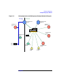
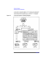
A Sample Workgroup / Network . . . . . . . . . . . . . . . . . . . . . . . . . . . . . . . . . . . . . . . . . . .
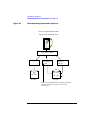
The MSW Network (Overview) . . . . . . . . . . . . . . . . . . . . . . . . . . . . . . . . . . . . . . . . . .
The MSW Network (System by System) . . . . . . . . . . . . . . . . . . . . . . . . . . . . . . . . . . .
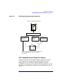
Setting Disk-Management Strategy . . . . . . . . . . . . . . . . . . . . . . . . . . . . . . . . . . . . . . . .
Distributing Disks . . . . . . . . . . . . . . . . . . . . . . . . . . . . . . . . . . . . . . . . . . . . . . . . . . . .
Capacity Planning . . . . . . . . . . . . . . . . . . . . . . . . . . . . . . . . . . . . . . . . . . . . . . . . . . . .
Disk-Management Tools . . . . . . . . . . . . . . . . . . . . . . . . . . . . . . . . . . . . . . . . . . . . . . . .
Planning to Manage File Systems. . . . . . . . . . . . . . . . . . . . . . . . . . . . . . . . . . . . . . . . . .
Introduction to Managing File Systems . . . . . . . . . . . . . . . . . . . . . . . . . . . . . . . . . . .
Journaled File System, the New File System Default . . . . . . . . . . . . . . . . . . . . . . . .
Frequently Asked Questions about the Journaled File System . . . . . . . . . . . . . . . . .
Managing Users Across Multiple Systems . . . . . . . . . . . . . . . . . . . . . . . . . . . . . . . . . . .
Guidelines . . . . . . . . . . . . . . . . . . . . . . . . . . . . . . . . . . . . . . . . . . . . . . . . . . . . . . . . . . .
Should You Share Users’ Home and Mail Directories?. . . . . . . . . . . . . . . . . . . . . . . .
30
30
32
33
36
36
37
39
42
42
44
53
53
54
56
60
60
63
64
79
79
80
7
Contents
Planning your Printer Configuration . . . . . . . . . . . . . . . . . . . . . . . . . . . . . . . . . . . . . . . 82
LP Spooler . . . . . . . . . . . . . . . . . . . . . . . . . . . . . . . . . . . . . . . . . . . . . . . . . . . . . . . . . . 82
HP Distributed Print Service (HPDPS). . . . . . . . . . . . . . . . . . . . . . . . . . . . . . . . . . . . 90
For More Information on Printer-Related Tasks . . . . . . . . . . . . . . . . . . . . . . . . . . . 100
Distributing Backups. . . . . . . . . . . . . . . . . . . . . . . . . . . . . . . . . . . . . . . . . . . . . . . . . . . 101
Using HP OpenView OmniBack II for Backup . . . . . . . . . . . . . . . . . . . . . . . . . . . . . 101
Services for Data Exchange with Personal Computers . . . . . . . . . . . . . . . . . . . . . . . . 103
File Transfer Tools . . . . . . . . . . . . . . . . . . . . . . . . . . . . . . . . . . . . . . . . . . . . . . . . . . . 103
Terminal Emulators . . . . . . . . . . . . . . . . . . . . . . . . . . . . . . . . . . . . . . . . . . . . . . . . . . 104
Versions of UNIX-like Operating Systems . . . . . . . . . . . . . . . . . . . . . . . . . . . . . . . . 105
Versions of the X Window System for PCs . . . . . . . . . . . . . . . . . . . . . . . . . . . . . . . . 106
Versions of the PC Windows Systems for HP-UX Systems . . . . . . . . . . . . . . . . . . . 107
NFS Mounts . . . . . . . . . . . . . . . . . . . . . . . . . . . . . . . . . . . . . . . . . . . . . . . . . . . . . . . . 107
Network Operating Systems . . . . . . . . . . . . . . . . . . . . . . . . . . . . . . . . . . . . . . . . . . . 108
Electronic Mail . . . . . . . . . . . . . . . . . . . . . . . . . . . . . . . . . . . . . . . . . . . . . . . . . . . . . . 108
Possible Problems Exchanging Data Between HP-UX and PCs . . . . . . . . . . . . . . . . . 109
ASCII End-of-Line Problems . . . . . . . . . . . . . . . . . . . . . . . . . . . . . . . . . . . . . . . . . . . 109
The Endian Difference Problem. . . . . . . . . . . . . . . . . . . . . . . . . . . . . . . . . . . . . . . . . 110
3. Configuring a System
Starting A Preloaded System . . . . . . . . . . . . . . . . . . . . . . . . . . . . . . . . . . . . . . . . . . . .
Using the CDE or HP VUE Desktop. . . . . . . . . . . . . . . . . . . . . . . . . . . . . . . . . . . . . . .
Using System Administration Manager (SAM) . . . . . . . . . . . . . . . . . . . . . . . . . . . . .
Using SAM versus HP-UX Commands . . . . . . . . . . . . . . . . . . . . . . . . . . . . . . . . . . .
Starting SAM . . . . . . . . . . . . . . . . . . . . . . . . . . . . . . . . . . . . . . . . . . . . . . . . . . . . . . .
Using SAM with an X Window System . . . . . . . . . . . . . . . . . . . . . . . . . . . . . . . . . .
Using SAM with a Text Terminal . . . . . . . . . . . . . . . . . . . . . . . . . . . . . . . . . . . . . . .
Using SAM for Remote System Administration . . . . . . . . . . . . . . . . . . . . . . . . . . .
Granting Users Limited Access to SAM . . . . . . . . . . . . . . . . . . . . . . . . . . . . . . . . . .
Displaying Device Information in SAM. . . . . . . . . . . . . . . . . . . . . . . . . . . . . . . . . . .
Controlling Access to a System . . . . . . . . . . . . . . . . . . . . . . . . . . . . . . . . . . . . . . . . . . .
Adding a User to a System . . . . . . . . . . . . . . . . . . . . . . . . . . . . . . . . . . . . . . . . . . . . .
Controlling File Access . . . . . . . . . . . . . . . . . . . . . . . . . . . . . . . . . . . . . . . . . . . . . . .
Controlling Usage and Processes with Run-Levels . . . . . . . . . . . . . . . . . . . . . . . . .
Adding Peripherals . . . . . . . . . . . . . . . . . . . . . . . . . . . . . . . . . . . . . . . . . . . . . . . . . . . .
Setting Up Non-HP Terminals . . . . . . . . . . . . . . . . . . . . . . . . . . . . . . . . . . . . . . . . .
8
114
116
117
117
118
118
119
119
119
120
121
121
126
128
130
130
Contents
Troubleshooting Problems with Terminals . . . . . . . . . . . . . . . . . . . . . . . . . . . . . . . .
Adding Processors with Instant Capacity On Demand (iCOD). . . . . . . . . . . . . . . . . .
Setting Up the Online Manpages . . . . . . . . . . . . . . . . . . . . . . . . . . . . . . . . . . . . . . . . .
Making Adjustments . . . . . . . . . . . . . . . . . . . . . . . . . . . . . . . . . . . . . . . . . . . . . . . . . . .
Setting the System Clock . . . . . . . . . . . . . . . . . . . . . . . . . . . . . . . . . . . . . . . . . . . . . .
Manually Setting Initial Information . . . . . . . . . . . . . . . . . . . . . . . . . . . . . . . . . . . .
Customizing System-Wide and User Login Environments . . . . . . . . . . . . . . . . . . .
Setting Up Mail Services . . . . . . . . . . . . . . . . . . . . . . . . . . . . . . . . . . . . . . . . . . . . . . . .
Components of an Electronic Mail System . . . . . . . . . . . . . . . . . . . . . . . . . . . . . . . .
Configuring a System to Send Electronic Mail . . . . . . . . . . . . . . . . . . . . . . . . . . . . .
Configuring a System to Receive Electronic Mail . . . . . . . . . . . . . . . . . . . . . . . . . . .
Reconfiguring the Kernel . . . . . . . . . . . . . . . . . . . . . . . . . . . . . . . . . . . . . . . . . . . . . . .
Steps to Reconfigure the Kernel . . . . . . . . . . . . . . . . . . . . . . . . . . . . . . . . . . . . . . . .
If the New Kernel Fails to Boot . . . . . . . . . . . . . . . . . . . . . . . . . . . . . . . . . . . . . . . . .
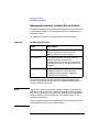
Managing Dynamically Loadable Kernel Modules . . . . . . . . . . . . . . . . . . . . . . . . . .
132
140
141
143
143
145
147
148
148
154
155
159
161
163
164
4. Configuring a Workgroup
Installing New Systems . . . . . . . . . . . . . . . . . . . . . . . . . . . . . . . . . . . . . . . . . . . . . . . . .
Configure New Systems into the Network . . . . . . . . . . . . . . . . . . . . . . . . . . . . . . . .
Configure New Systems into a Workgroup . . . . . . . . . . . . . . . . . . . . . . . . . . . . . . . .
Adding Users to a Workgroup . . . . . . . . . . . . . . . . . . . . . . . . . . . . . . . . . . . . . . . . . . . .
Accessing Multiple Systems . . . . . . . . . . . . . . . . . . . . . . . . . . . . . . . . . . . . . . . . . . . .
Sharing Remote Work Directories . . . . . . . . . . . . . . . . . . . . . . . . . . . . . . . . . . . . . . .
Local versus Remote Home Directories . . . . . . . . . . . . . . . . . . . . . . . . . . . . . . . . . . .
Adding a User to Several Systems: A Case Study . . . . . . . . . . . . . . . . . . . . . . . . . .
Exporting a Local Home Directory . . . . . . . . . . . . . . . . . . . . . . . . . . . . . . . . . . . . . .
Implementing Disk-Management Strategy . . . . . . . . . . . . . . . . . . . . . . . . . . . . . . . . .
Sharing Files and Applications via NFS and ftp . . . . . . . . . . . . . . . . . . . . . . . . . . . . .
Exporting a File System (HP-UX to HP-UX) . . . . . . . . . . . . . . . . . . . . . . . . . . . . . .
Importing a File System (HP-UX to HP-UX) . . . . . . . . . . . . . . . . . . . . . . . . . . . . . .
Importing HP-UX Directories to NT . . . . . . . . . . . . . . . . . . . . . . . . . . . . . . . . . . . . .
Troubleshooting NFS . . . . . . . . . . . . . . . . . . . . . . . . . . . . . . . . . . . . . . . . . . . . . . . . .
Recovering Network Services after a Power Failure. . . . . . . . . . . . . . . . . . . . . . . . .
Moving or Reusing an Exported Directory . . . . . . . . . . . . . . . . . . . . . . . . . . . . . . . .
Configuring Anonymous ftp . . . . . . . . . . . . . . . . . . . . . . . . . . . . . . . . . . . . . . . . . . . .
Troubleshooting ftp login . . . . . . . . . . . . . . . . . . . . . . . . . . . . . . . . . . . . . . . . . . . . . .
Adding PC/NT Systems into the Workgroup . . . . . . . . . . . . . . . . . . . . . . . . . . . . . . . .
Hardware Connections . . . . . . . . . . . . . . . . . . . . . . . . . . . . . . . . . . . . . . . . . . . . . . . .
196
196
199
200
200
200
201
201
204
205
206
207
208
212
215
218
220
220
222
224
224
9
Contents
Configuring HP-UX Systems for Terminal Emulation . . . . . . . . . . . . . . . . . . . . . . .
Configuring HP-UX Systems for File Transfer . . . . . . . . . . . . . . . . . . . . . . . . . . . . .
Mounting File Systems Between HP-UX and PCs . . . . . . . . . . . . . . . . . . . . . . . . .
Configuring Printers for a Workgroup . . . . . . . . . . . . . . . . . . . . . . . . . . . . . . . . . . . . .
Configuring Printers to Use the LP Spooler . . . . . . . . . . . . . . . . . . . . . . . . . . . . . . .
Configuring Printers to Use HPDPS . . . . . . . . . . . . . . . . . . . . . . . . . . . . . . . . . . . . .
Compatibility Between HP-UX Releases 10.x and 11.x. . . . . . . . . . . . . . . . . . . . . . . .
HP-UX 10.x to 11.0 Compatibility . . . . . . . . . . . . . . . . . . . . . . . . . . . . . . . . . . . . . . .
Exchanging Data Between 32-bit and 64-bit Applications. . . . . . . . . . . . . . . . . . . .
Large File Compatibility . . . . . . . . . . . . . . . . . . . . . . . . . . . . . . . . . . . . . . . . . . . . . .
NFS Compatibility and Large File Support . . . . . . . . . . . . . . . . . . . . . . . . . . . . . . .
NFS Interoperability Matrix . . . . . . . . . . . . . . . . . . . . . . . . . . . . . . . . . . . . . . . . . . .
225
228
243
244
244
255
258
258
264
265
267
269
5. Administering a System: Booting and Shutdown
Booting Systems . . . . . . . . . . . . . . . . . . . . . . . . . . . . . . . . . . . . . . . . . . . . . . . . . . . . . . .
The Boot Sequence: Starting an HP-UX System . . . . . . . . . . . . . . . . . . . . . . . . . . .
Booting HP-UX: Details and Variations . . . . . . . . . . . . . . . . . . . . . . . . . . . . . . . . . .
Tasks Affecting the Boot Process . . . . . . . . . . . . . . . . . . . . . . . . . . . . . . . . . . . . . . . . .
Enabling / Disabling Autoboot . . . . . . . . . . . . . . . . . . . . . . . . . . . . . . . . . . . . . . . . . .
Enabling / Disabling Autosearch . . . . . . . . . . . . . . . . . . . . . . . . . . . . . . . . . . . . . . . .
Changing the Primary/Alternate Boot Paths . . . . . . . . . . . . . . . . . . . . . . . . . . . . . .
Setting Initial System Information . . . . . . . . . . . . . . . . . . . . . . . . . . . . . . . . . . . . . .
Changing the Contents of the Autoexecute File . . . . . . . . . . . . . . . . . . . . . . . . . . . .
Speeding the Boot: SpeedyBoot . . . . . . . . . . . . . . . . . . . . . . . . . . . . . . . . . . . . . . . . .
Customizing Start-up and Shutdown . . . . . . . . . . . . . . . . . . . . . . . . . . . . . . . . . . . . . .
Shutting Down Systems . . . . . . . . . . . . . . . . . . . . . . . . . . . . . . . . . . . . . . . . . . . . . . . .
Overview of the Shutdown Process . . . . . . . . . . . . . . . . . . . . . . . . . . . . . . . . . . . . . .
Types of Shutdown . . . . . . . . . . . . . . . . . . . . . . . . . . . . . . . . . . . . . . . . . . . . . . . . . . .
Special Considerations for Shutting Down Certain Systems. . . . . . . . . . . . . . . . . .
Avoiding a Shutdown When Possible. . . . . . . . . . . . . . . . . . . . . . . . . . . . . . . . . . . . .
Abnormal System Shutdowns . . . . . . . . . . . . . . . . . . . . . . . . . . . . . . . . . . . . . . . . . . . .
Overview of the Dump / Save Cycle . . . . . . . . . . . . . . . . . . . . . . . . . . . . . . . . . . . . . .
Preparing for a System Crash . . . . . . . . . . . . . . . . . . . . . . . . . . . . . . . . . . . . . . . . . .
What Happens When the System Crashes . . . . . . . . . . . . . . . . . . . . . . . . . . . . . . . .
What To Do After the System Has Rebooted. . . . . . . . . . . . . . . . . . . . . . . . . . . . . . .
10
272
272
273
283
283
285
286
287
289
290
296
301
301
303
308
311
312
313
314
327
329
Contents
6. Administering a System: Managing Disks and Files
Managing Disks . . . . . . . . . . . . . . . . . . . . . . . . . . . . . . . . . . . . . . . . . . . . . . . . . . . . . . .
Current Disk Management Facts. . . . . . . . . . . . . . . . . . . . . . . . . . . . . . . . . . . . . . . .
The Logical Volume Manager (LVM) . . . . . . . . . . . . . . . . . . . . . . . . . . . . . . . . . . . . .
Planning for the Use of Logical Volumes. . . . . . . . . . . . . . . . . . . . . . . . . . . . . . . . . .
LVM Naming Conventions . . . . . . . . . . . . . . . . . . . . . . . . . . . . . . . . . . . . . . . . . . . . .
Managing Logical Volumes Using SAM . . . . . . . . . . . . . . . . . . . . . . . . . . . . . . . . . .
Managing Logical Volumes Using HP-UX Commands . . . . . . . . . . . . . . . . . . . . . .
Tasks That You Can Perform Only with HP-UX Commands . . . . . . . . . . . . . . . . . .
LVM Procedures . . . . . . . . . . . . . . . . . . . . . . . . . . . . . . . . . . . . . . . . . . . . . . . . . . . . .
LVM Troubleshooting . . . . . . . . . . . . . . . . . . . . . . . . . . . . . . . . . . . . . . . . . . . . . . . . .
Managing File Systems . . . . . . . . . . . . . . . . . . . . . . . . . . . . . . . . . . . . . . . . . . . . . . . . .
Creating a File System . . . . . . . . . . . . . . . . . . . . . . . . . . . . . . . . . . . . . . . . . . . . . . . .
Mounting File Systems . . . . . . . . . . . . . . . . . . . . . . . . . . . . . . . . . . . . . . . . . . . . . . .
Unmounting File Systems . . . . . . . . . . . . . . . . . . . . . . . . . . . . . . . . . . . . . . . . . . . . .
Extending the Size of a File System Within a Logical Volume . . . . . . . . . . . . . . . .
Copying a File System Across Devices . . . . . . . . . . . . . . . . . . . . . . . . . . . . . . . . . . .
Dealing with File System Corruption . . . . . . . . . . . . . . . . . . . . . . . . . . . . . . . . . . . .
Replacing an Existing File System with a Smaller One . . . . . . . . . . . . . . . . . . . . .
Managing Disk Space Usage with Quotas . . . . . . . . . . . . . . . . . . . . . . . . . . . . . . . .
Managing Mirrored File Systems . . . . . . . . . . . . . . . . . . . . . . . . . . . . . . . . . . . . . . .
Defragmenting a JFS File System . . . . . . . . . . . . . . . . . . . . . . . . . . . . . . . . . . . . . . .
Converting Existing File Systems to JFS . . . . . . . . . . . . . . . . . . . . . . . . . . . . . . . . .
Resizing a JFS File System . . . . . . . . . . . . . . . . . . . . . . . . . . . . . . . . . . . . . . . . . . . .
Examples and Cookbook Procedures . . . . . . . . . . . . . . . . . . . . . . . . . . . . . . . . . . . . .
Managing Large Files. . . . . . . . . . . . . . . . . . . . . . . . . . . . . . . . . . . . . . . . . . . . . . . . .
Managing FTP . . . . . . . . . . . . . . . . . . . . . . . . . . . . . . . . . . . . . . . . . . . . . . . . . . . . . .
Managing Swap and Dump . . . . . . . . . . . . . . . . . . . . . . . . . . . . . . . . . . . . . . . . . . . . . .
Types of Swap Space . . . . . . . . . . . . . . . . . . . . . . . . . . . . . . . . . . . . . . . . . . . . . . . . .
Primary and Secondary Swap . . . . . . . . . . . . . . . . . . . . . . . . . . . . . . . . . . . . . . . . . .
Designing Your Swap Space Allocation . . . . . . . . . . . . . . . . . . . . . . . . . . . . . . . . . . .
Adding, Modifying, or Removing File System Swap . . . . . . . . . . . . . . . . . . . . . . . .
Configuring Primary and Secondary Swap . . . . . . . . . . . . . . . . . . . . . . . . . . . . . . .
Configuring Dump . . . . . . . . . . . . . . . . . . . . . . . . . . . . . . . . . . . . . . . . . . . . . . . . . . .
Backing Up Data . . . . . . . . . . . . . . . . . . . . . . . . . . . . . . . . . . . . . . . . . . . . . . . . . . . . . .
Choosing the Type of Storage Device. . . . . . . . . . . . . . . . . . . . . . . . . . . . . . . . . . . . .
Choosing a Backup/Recovery Utility . . . . . . . . . . . . . . . . . . . . . . . . . . . . . . . . . . . . .
Determining What Data to Back Up . . . . . . . . . . . . . . . . . . . . . . . . . . . . . . . . . . . . .
334
334
335
339
344
347
347
352
366
367
373
374
376
380
382
383
384
389
391
397
407
408
416
418
418
421
425
425
426
427
431
433
434
437
438
439
444
11
Contents
Determining How Often to Back Up Data. . . . . . . . . . . . . . . . . . . . . . . . . . . . . . . . .
Backing Up Your Data Using the fbackup Command . . . . . . . . . . . . . . . . . . . . . . .
Examples of fbackup Commands . . . . . . . . . . . . . . . . . . . . . . . . . . . . . . . . . . . . . . . .
Backing Up Files on a Remote System . . . . . . . . . . . . . . . . . . . . . . . . . . . . . . . . . . .
Setting Up an Automated Backup Schedule . . . . . . . . . . . . . . . . . . . . . . . . . . . . . . .
Creating an Automated Backup Schedule. . . . . . . . . . . . . . . . . . . . . . . . . . . . . . . . .
Displaying an Automated Backup Schedule . . . . . . . . . . . . . . . . . . . . . . . . . . . . . . .
Activating an Automated Backup Schedule . . . . . . . . . . . . . . . . . . . . . . . . . . . . . . .
Backing Up If You Are Using LVM . . . . . . . . . . . . . . . . . . . . . . . . . . . . . . . . . . . . . .
Backing Up Large Files . . . . . . . . . . . . . . . . . . . . . . . . . . . . . . . . . . . . . . . . . . . . . . .
Backing Up a JFS Snapshot File System . . . . . . . . . . . . . . . . . . . . . . . . . . . . . . . . .
Restoring Your Data. . . . . . . . . . . . . . . . . . . . . . . . . . . . . . . . . . . . . . . . . . . . . . . . . . . .
Determining What Data to Restore . . . . . . . . . . . . . . . . . . . . . . . . . . . . . . . . . . . . . .
Restoring Data From Releases Prior to 10.0 HP-UX . . . . . . . . . . . . . . . . . . . . . . . .
Before Restoring Your Data . . . . . . . . . . . . . . . . . . . . . . . . . . . . . . . . . . . . . . . . . . . .
Restoring Your Data Using SAM . . . . . . . . . . . . . . . . . . . . . . . . . . . . . . . . . . . . . . .
Restoring Your Data Using HP-UX Commands . . . . . . . . . . . . . . . . . . . . . . . . . . . .
Recovering From a System Crash . . . . . . . . . . . . . . . . . . . . . . . . . . . . . . . . . . . . . . .
445
447
450
451
452
452
454
454
455
455
456
459
459
460
460
460
460
462
7. Administering a System: Managing Printers, Software, and Performance
Managing Printers . . . . . . . . . . . . . . . . . . . . . . . . . . . . . . . . . . . . . . . . . . . . . . . . . . . . .
Administering the LP Spooler . . . . . . . . . . . . . . . . . . . . . . . . . . . . . . . . . . . . . . . . . .
Administering HP Distributed Print Service (HPDPS) . . . . . . . . . . . . . . . . . . . . . .
Managing Software . . . . . . . . . . . . . . . . . . . . . . . . . . . . . . . . . . . . . . . . . . . . . . . . . . . .
SD-UX Software Structure. . . . . . . . . . . . . . . . . . . . . . . . . . . . . . . . . . . . . . . . . . . . .
Location of Software . . . . . . . . . . . . . . . . . . . . . . . . . . . . . . . . . . . . . . . . . . . . . . . . . .
SD-UX Tasks . . . . . . . . . . . . . . . . . . . . . . . . . . . . . . . . . . . . . . . . . . . . . . . . . . . . . . . .
SD-UX Roles . . . . . . . . . . . . . . . . . . . . . . . . . . . . . . . . . . . . . . . . . . . . . . . . . . . . . . . .
About Patches. . . . . . . . . . . . . . . . . . . . . . . . . . . . . . . . . . . . . . . . . . . . . . . . . . . . . . . . .
Recommended Patches - Extension Software . . . . . . . . . . . . . . . . . . . . . . . . . . . . . .
Removing Patches . . . . . . . . . . . . . . . . . . . . . . . . . . . . . . . . . . . . . . . . . . . . . . . . . . . .
Managing System Performance. . . . . . . . . . . . . . . . . . . . . . . . . . . . . . . . . . . . . . . . . . .
Performance Bottlenecks . . . . . . . . . . . . . . . . . . . . . . . . . . . . . . . . . . . . . . . . . . . . . .
Guidelines . . . . . . . . . . . . . . . . . . . . . . . . . . . . . . . . . . . . . . . . . . . . . . . . . . . . . . . . . .
Measuring Performance . . . . . . . . . . . . . . . . . . . . . . . . . . . . . . . . . . . . . . . . . . . . . . .
Making Changes . . . . . . . . . . . . . . . . . . . . . . . . . . . . . . . . . . . . . . . . . . . . . . . . . . . . .
12
466
466
474
477
477
479
480
484
486
486
487
488
488
489
491
496
Contents
Other Performance Management Tools . . . . . . . . . . . . . . . . . . . . . . . . . . . . . . . . . . . 498
8. Administering a System: Managing System Security
Standard System Security . . . . . . . . . . . . . . . . . . . . . . . . . . . . . . . . . . . . . . . . . . . . . . .
Planning System Security . . . . . . . . . . . . . . . . . . . . . . . . . . . . . . . . . . . . . . . . . . . . . . .
Common Security Practices . . . . . . . . . . . . . . . . . . . . . . . . . . . . . . . . . . . . . . . . . . . .
Maintaining System Security. . . . . . . . . . . . . . . . . . . . . . . . . . . . . . . . . . . . . . . . . . .
Basic Guidelines . . . . . . . . . . . . . . . . . . . . . . . . . . . . . . . . . . . . . . . . . . . . . . . . . . . . .
Obtaining HP-UX Security Bulletins . . . . . . . . . . . . . . . . . . . . . . . . . . . . . . . . . . . .
Security Choices . . . . . . . . . . . . . . . . . . . . . . . . . . . . . . . . . . . . . . . . . . . . . . . . . . . . .
Managing Standard Passwords and System Access . . . . . . . . . . . . . . . . . . . . . . . . . .
Criteria of a Good Password. . . . . . . . . . . . . . . . . . . . . . . . . . . . . . . . . . . . . . . . . . . .
Password File . . . . . . . . . . . . . . . . . . . . . . . . . . . . . . . . . . . . . . . . . . . . . . . . . . . . . . .
Eliminating Pseudo-Accounts and Protecting Key Subsystems . . . . . . . . . . . . . . .
System Access by Modem . . . . . . . . . . . . . . . . . . . . . . . . . . . . . . . . . . . . . . . . . . . . . .
Protecting Programs from Illegal Execution . . . . . . . . . . . . . . . . . . . . . . . . . . . . . . .
Managing Access to Files and Directories . . . . . . . . . . . . . . . . . . . . . . . . . . . . . . . . . .
Using HFS Access Control Lists (ACLs) . . . . . . . . . . . . . . . . . . . . . . . . . . . . . . . . . .
Using JFS Access Control Lists (ACLs). . . . . . . . . . . . . . . . . . . . . . . . . . . . . . . . . . .
Comparison of JFS and HFS ACLs . . . . . . . . . . . . . . . . . . . . . . . . . . . . . . . . . . . . . .
ACLs in a Network Environment . . . . . . . . . . . . . . . . . . . . . . . . . . . . . . . . . . . . . . .
Setting Default Permissions. . . . . . . . . . . . . . . . . . . . . . . . . . . . . . . . . . . . . . . . . . . .
Protecting Directories. . . . . . . . . . . . . . . . . . . . . . . . . . . . . . . . . . . . . . . . . . . . . . . . .
Protecting User Accounts . . . . . . . . . . . . . . . . . . . . . . . . . . . . . . . . . . . . . . . . . . . . . .
Security Considerations for Device Files. . . . . . . . . . . . . . . . . . . . . . . . . . . . . . . . . .
Protecting Disk Partitions and Logical Volumes . . . . . . . . . . . . . . . . . . . . . . . . . . .
Guidelines for Running a Secure System . . . . . . . . . . . . . . . . . . . . . . . . . . . . . . . . . . .
Guidelines for Handling Setuid and Setgid Programs . . . . . . . . . . . . . . . . . . . . . . .
Guidelines for System Initialization . . . . . . . . . . . . . . . . . . . . . . . . . . . . . . . . . . . . .
Guidelines for Trusted Backup and Recovery . . . . . . . . . . . . . . . . . . . . . . . . . . . . . .
Guidelines for Mounting and Unmounting a File System . . . . . . . . . . . . . . . . . . . .
Guidelines for Handling Security Breaches . . . . . . . . . . . . . . . . . . . . . . . . . . . . . . .
Tracking Root . . . . . . . . . . . . . . . . . . . . . . . . . . . . . . . . . . . . . . . . . . . . . . . . . . . . . . .
Controlling Security on a Network . . . . . . . . . . . . . . . . . . . . . . . . . . . . . . . . . . . . . . . .
Controlling an Administrative Domain . . . . . . . . . . . . . . . . . . . . . . . . . . . . . . . . . . .
Verifying Permission Settings on Network Control Files. . . . . . . . . . . . . . . . . . . . .
Understanding Network Services . . . . . . . . . . . . . . . . . . . . . . . . . . . . . . . . . . . . . . .
Using inetd.sec to Restrict Outside Access . . . . . . . . . . . . . . . . . . . . . . . . . . . . . . . .
505
506
506
507
507
508
509
510
510
511
512
513
514
515
516
520
532
533
533
533
534
534
536
537
537
540
540
542
543
545
546
546
547
548
548
13
Contents
Denying Access with /etc/ftpd/ftpusers . . . . . . . . . . . . . . . . . . . . . . . . . . . . . . . . . . .
Files Mounted in an NFS Environment . . . . . . . . . . . . . . . . . . . . . . . . . . . . . . . . . .
Link-Level Access . . . . . . . . . . . . . . . . . . . . . . . . . . . . . . . . . . . . . . . . . . . . . . . . . . . .
Trusted System Security . . . . . . . . . . . . . . . . . . . . . . . . . . . . . . . . . . . . . . . . . . . . . . . .
Setting Up Your Trusted System . . . . . . . . . . . . . . . . . . . . . . . . . . . . . . . . . . . . . . . . .
Auditing a Trusted System . . . . . . . . . . . . . . . . . . . . . . . . . . . . . . . . . . . . . . . . . . . . . .
Streamlining Audit Log Data. . . . . . . . . . . . . . . . . . . . . . . . . . . . . . . . . . . . . . . . . . .
Self-Auditing Programs . . . . . . . . . . . . . . . . . . . . . . . . . . . . . . . . . . . . . . . . . . . . . . .
Audit Log Files . . . . . . . . . . . . . . . . . . . . . . . . . . . . . . . . . . . . . . . . . . . . . . . . . . . . . .
Viewing Audit Logs. . . . . . . . . . . . . . . . . . . . . . . . . . . . . . . . . . . . . . . . . . . . . . . . . . .
Guidelines for Administering Your Auditing System . . . . . . . . . . . . . . . . . . . . . . . .
Performance Considerations . . . . . . . . . . . . . . . . . . . . . . . . . . . . . . . . . . . . . . . . . . .
Using Auditing in an NFS Diskless Environment . . . . . . . . . . . . . . . . . . . . . . . . . .
Managing Trusted Passwords and System Access. . . . . . . . . . . . . . . . . . . . . . . . . . . .
Criteria of a Good Password. . . . . . . . . . . . . . . . . . . . . . . . . . . . . . . . . . . . . . . . . . . .
Password Files . . . . . . . . . . . . . . . . . . . . . . . . . . . . . . . . . . . . . . . . . . . . . . . . . . . . . .
Password Selection and Generation . . . . . . . . . . . . . . . . . . . . . . . . . . . . . . . . . . . . .
Password Aging. . . . . . . . . . . . . . . . . . . . . . . . . . . . . . . . . . . . . . . . . . . . . . . . . . . . . .
Password History and Password Reuse. . . . . . . . . . . . . . . . . . . . . . . . . . . . . . . . . . .
Time-Based Access Control . . . . . . . . . . . . . . . . . . . . . . . . . . . . . . . . . . . . . . . . . . . .
Device-Based Access Control . . . . . . . . . . . . . . . . . . . . . . . . . . . . . . . . . . . . . . . . . . .
Manipulating the Trusted System Databases. . . . . . . . . . . . . . . . . . . . . . . . . . . . . .
Configuring NFS Diskless Clusters for Trusted Systems . . . . . . . . . . . . . . . . . . . . . .
Choice 1: Clusters with Private Password Databases . . . . . . . . . . . . . . . . . . . . . . .
Choice 2: Clusters with Shared Password Databases. . . . . . . . . . . . . . . . . . . . . . . .
Optional Security Packages. . . . . . . . . . . . . . . . . . . . . . . . . . . . . . . . . . . . . . . . . . . . . .
Using Pluggable Authentication Modules (PAM). . . . . . . . . . . . . . . . . . . . . . . . . . . . .
Using SAM with PAM. . . . . . . . . . . . . . . . . . . . . . . . . . . . . . . . . . . . . . . . . . . . . . . . .
System-Wide Configuration . . . . . . . . . . . . . . . . . . . . . . . . . . . . . . . . . . . . . . . . . . . .
Per-User Configuration. . . . . . . . . . . . . . . . . . . . . . . . . . . . . . . . . . . . . . . . . . . . . . . .
The pam.conf Configuration File . . . . . . . . . . . . . . . . . . . . . . . . . . . . . . . . . . . . . . . .
The pam_user.conf Configuration File. . . . . . . . . . . . . . . . . . . . . . . . . . . . . . . . . . . .
How PAM Works: A Login Example . . . . . . . . . . . . . . . . . . . . . . . . . . . . . . . . . . . . .
Using Network Information Service Plus (NIS+). . . . . . . . . . . . . . . . . . . . . . . . . . . . .
Using SAM with NIS+ . . . . . . . . . . . . . . . . . . . . . . . . . . . . . . . . . . . . . . . . . . . . . . . .
Setting up NIS+ with Trusted Mode . . . . . . . . . . . . . . . . . . . . . . . . . . . . . . . . . . . . .
14
549
549
551
552
553
555
559
560
561
561
562
563
563
564
565
566
569
569
570
570
571
571
573
573
574
578
579
580
580
581
581
584
585
587
588
588
Contents
NIS+ Trusted Table and the ttsyncd Daemon. . . . . . . . . . . . . . . . . . . . . . . . . . . . . .
Secure Internet Services (SIS) . . . . . . . . . . . . . . . . . . . . . . . . . . . . . . . . . . . . . . . . . . .
Environment . . . . . . . . . . . . . . . . . . . . . . . . . . . . . . . . . . . . . . . . . . . . . . . . . . . . . . . .
Operating with Secure and Nonsecure Systems . . . . . . . . . . . . . . . . . . . . . . . . . . . .
Intrusion Detection System (IDS/9000) . . . . . . . . . . . . . . . . . . . . . . . . . . . . . . . . . . . .
Common Data Security Architecture (CDSA) . . . . . . . . . . . . . . . . . . . . . . . . . . . . . . .
589
591
592
592
593
594
9. Administering a Workgroup
Managing Disks . . . . . . . . . . . . . . . . . . . . . . . . . . . . . . . . . . . . . . . . . . . . . . . . . . . . . . .
Examples . . . . . . . . . . . . . . . . . . . . . . . . . . . . . . . . . . . . . . . . . . . . . . . . . . . . . . . . . . .
How To: . . . . . . . . . . . . . . . . . . . . . . . . . . . . . . . . . . . . . . . . . . . . . . . . . . . . . . . . . . . . . .
Determining What Version of the HP-UX Operating System is Running. . . . . . . .
Backing Up and Recovering Directories: Quick Reference for tar . . . . . . . . . . . . . .
Breaking Out of the Boot Screen (10.x/11.x) . . . . . . . . . . . . . . . . . . . . . . . . . . . . . . .
Checking the System’s Run Level . . . . . . . . . . . . . . . . . . . . . . . . . . . . . . . . . . . . . . .
Diagramming a System’s Disk Usage . . . . . . . . . . . . . . . . . . . . . . . . . . . . . . . . . . . .
Finding Large Files. . . . . . . . . . . . . . . . . . . . . . . . . . . . . . . . . . . . . . . . . . . . . . . . . . .
Examining File System Characteristics . . . . . . . . . . . . . . . . . . . . . . . . . . . . . . . . . .
Moving a Directory (within a File System) . . . . . . . . . . . . . . . . . . . . . . . . . . . . . . . .
Moving a System. . . . . . . . . . . . . . . . . . . . . . . . . . . . . . . . . . . . . . . . . . . . . . . . . . . . .
Popping the Directory Stack. . . . . . . . . . . . . . . . . . . . . . . . . . . . . . . . . . . . . . . . . . . .
Scheduling a cron Job . . . . . . . . . . . . . . . . . . . . . . . . . . . . . . . . . . . . . . . . . . . . . . . . .
Continuing to Work During a Scheduled Downtime. . . . . . . . . . . . . . . . . . . . . . . . .
Troubleshooting . . . . . . . . . . . . . . . . . . . . . . . . . . . . . . . . . . . . . . . . . . . . . . . . . . . . . . .
Tips on Interpreting HP-UX Error Messages . . . . . . . . . . . . . . . . . . . . . . . . . . . . . .
Enabling Internet Services Governed by inetd . . . . . . . . . . . . . . . . . . . . . . . . . . . . .
Adding Software to a Workgroup . . . . . . . . . . . . . . . . . . . . . . . . . . . . . . . . . . . . . . . . .
Installing and Managing Software For an Enterprise . . . . . . . . . . . . . . . . . . . . . . .
Setting up a Network Host (Building a Depot) . . . . . . . . . . . . . . . . . . . . . . . . . . . . .
Other Workgroup Management Tools . . . . . . . . . . . . . . . . . . . . . . . . . . . . . . . . . . . . . .
597
598
614
615
615
617
617
618
620
621
621
622
623
623
624
625
626
626
628
628
628
631
10. Setting Up and Administering an HP-UX NFS Diskless Cluster
What Is an NFS Diskless Cluster? . . . . . . . . . . . . . . . . . . . . . . . . . . . . . . . . . . . . . . . .
Reasons for Creating an NFS Diskless Cluster . . . . . . . . . . . . . . . . . . . . . . . . . . . .
Terminology . . . . . . . . . . . . . . . . . . . . . . . . . . . . . . . . . . . . . . . . . . . . . . . . . . . . . . . .
Planning Your Cluster Policies . . . . . . . . . . . . . . . . . . . . . . . . . . . . . . . . . . . . . . . . . . .
Policies for the Location of User and Group Data . . . . . . . . . . . . . . . . . . . . . . . . . .
Policies for the Location of Home Directories . . . . . . . . . . . . . . . . . . . . . . . . . . . . .
635
636
636
638
639
639
15
Contents
Policies for Electronic Mail . . . . . . . . . . . . . . . . . . . . . . . . . . . . . . . . . . . . . . . . . . . .
Setting Up NFS Cluster Hardware . . . . . . . . . . . . . . . . . . . . . . . . . . . . . . . . . . . . . . .
Peripherals . . . . . . . . . . . . . . . . . . . . . . . . . . . . . . . . . . . . . . . . . . . . . . . . . . . . . . . . .
Local Area Network (LAN) . . . . . . . . . . . . . . . . . . . . . . . . . . . . . . . . . . . . . . . . . . . .
Disk Storage . . . . . . . . . . . . . . . . . . . . . . . . . . . . . . . . . . . . . . . . . . . . . . . . . . . . . . . .
Obtaining Information About Your Server and Client . . . . . . . . . . . . . . . . . . . . . . . .
Getting the Hardware (Station) Address . . . . . . . . . . . . . . . . . . . . . . . . . . . . . . . . .
Installing Diskless Software . . . . . . . . . . . . . . . . . . . . . . . . . . . . . . . . . . . . . . . . . . . . .
Installing a Series 700 Client on a Series 800 Cluster Server . . . . . . . . . . . . . . . . . .
Configuring a Relay Agent . . . . . . . . . . . . . . . . . . . . . . . . . . . . . . . . . . . . . . . . . . . . . .
Setting Up the Cluster Server. . . . . . . . . . . . . . . . . . . . . . . . . . . . . . . . . . . . . . . . . . . .
A Preview of What You Will Need to Do . . . . . . . . . . . . . . . . . . . . . . . . . . . . . . . . . .
Help Information for NFS Diskless Clusters . . . . . . . . . . . . . . . . . . . . . . . . . . . . . .
Setting the Policies for a Cluster . . . . . . . . . . . . . . . . . . . . . . . . . . . . . . . . . . . . . . . .
Adding Clients to a Cluster . . . . . . . . . . . . . . . . . . . . . . . . . . . . . . . . . . . . . . . . . . . .
Booting New Clients . . . . . . . . . . . . . . . . . . . . . . . . . . . . . . . . . . . . . . . . . . . . . . . . . . .
What To Do Next . . . . . . . . . . . . . . . . . . . . . . . . . . . . . . . . . . . . . . . . . . . . . . . . . . . . . .
Adding a Local Disk . . . . . . . . . . . . . . . . . . . . . . . . . . . . . . . . . . . . . . . . . . . . . . . . . .
Administering Your NFS Diskless Cluster. . . . . . . . . . . . . . . . . . . . . . . . . . . . . . . . . .
NFS Diskless Questions and Answers . . . . . . . . . . . . . . . . . . . . . . . . . . . . . . . . . . . . .
Cluster Configuration . . . . . . . . . . . . . . . . . . . . . . . . . . . . . . . . . . . . . . . . . . . . . . . .
Performance . . . . . . . . . . . . . . . . . . . . . . . . . . . . . . . . . . . . . . . . . . . . . . . . . . . . . . . .
Single Point Administration . . . . . . . . . . . . . . . . . . . . . . . . . . . . . . . . . . . . . . . . . . .
640
641
641
642
642
644
645
647
649
651
654
654
654
655
655
660
662
662
664
668
668
674
676
A. Using High Availability Strategies
Using Software Mirroring as a Disk Protection Strategy . . . . . . . . . . . . . . . . . . . . . .
Using Disk Arrays . . . . . . . . . . . . . . . . . . . . . . . . . . . . . . . . . . . . . . . . . . . . . . . . . . . . .
Disk Arrays Using RAID Data Protection Strategies . . . . . . . . . . . . . . . . . . . . . . . . .
Mirroring (RAID Level 1) . . . . . . . . . . . . . . . . . . . . . . . . . . . . . . . . . . . . . . . . . . . . . .
Disk Striping (RAID Level 0) . . . . . . . . . . . . . . . . . . . . . . . . . . . . . . . . . . . . . . . . . . .
RAID 3 . . . . . . . . . . . . . . . . . . . . . . . . . . . . . . . . . . . . . . . . . . . . . . . . . . . . . . . . . . . . .
RAID 5 . . . . . . . . . . . . . . . . . . . . . . . . . . . . . . . . . . . . . . . . . . . . . . . . . . . . . . . . . . . . .
What is AutoRAID? . . . . . . . . . . . . . . . . . . . . . . . . . . . . . . . . . . . . . . . . . . . . . . . . . . . .
Pros and Cons of AutoRAID . . . . . . . . . . . . . . . . . . . . . . . . . . . . . . . . . . . . . . . . . . . .
Recommended Uses of AutoRAID . . . . . . . . . . . . . . . . . . . . . . . . . . . . . . . . . . . . . . .
HP SureStore E Disk Array. . . . . . . . . . . . . . . . . . . . . . . . . . . . . . . . . . . . . . . . . . . . . .
16
684
685
686
686
686
687
688
689
689
689
690
Contents
Using Hot Spared Disks . . . . . . . . . . . . . . . . . . . . . . . . . . . . . . . . . . . . . . . . . . . . . . . .
Using High Available Storage Systems (HASS). . . . . . . . . . . . . . . . . . . . . . . . . . . . . .
Pros and Cons of HASS . . . . . . . . . . . . . . . . . . . . . . . . . . . . . . . . . . . . . . . . . . . . . . .
Recommended Uses of HASS . . . . . . . . . . . . . . . . . . . . . . . . . . . . . . . . . . . . . . . . . . .
Using MC/ServiceGuard . . . . . . . . . . . . . . . . . . . . . . . . . . . . . . . . . . . . . . . . . . . . . . . .
Pros and Cons of MC/ServiceGuard. . . . . . . . . . . . . . . . . . . . . . . . . . . . . . . . . . . . . .
MC/ServiceGuard Features . . . . . . . . . . . . . . . . . . . . . . . . . . . . . . . . . . . . . . . . . . . .
Other High Availability Products and Features. . . . . . . . . . . . . . . . . . . . . . . . . . . . . .
High Availability Monitors. . . . . . . . . . . . . . . . . . . . . . . . . . . . . . . . . . . . . . . . . . . . .
Enterprise Cluster Master Toolkit. . . . . . . . . . . . . . . . . . . . . . . . . . . . . . . . . . . . . . .
MetroCluster . . . . . . . . . . . . . . . . . . . . . . . . . . . . . . . . . . . . . . . . . . . . . . . . . . . . . . . .
ContinentalClusters . . . . . . . . . . . . . . . . . . . . . . . . . . . . . . . . . . . . . . . . . . . . . . . . . .
HP ServiceControl . . . . . . . . . . . . . . . . . . . . . . . . . . . . . . . . . . . . . . . . . . . . . . . . . . .
691
692
692
692
693
693
694
696
696
696
696
697
698
17
Contents
18
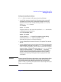
What's in This Document
This document:
• Supports HP-UX 11.x, including 64-bit functionality, as well as
HP-UX 10.x.
• Covers administration of interdependent workgroups, as well as
single systems.
It includes the following major topics:
• Chapter 1, “Systems and Workgroups,” on page 21
Definition of terms and categories.
• Chapter 2, “Planning a Workgroup,” on page 29
Choosing among alternative models for distributing applications,
data and other computing resources.
• Chapter 3, “Configuring a System,” on page 113
Setting up an individual workstation or server.
• Chapter 4, “Configuring a Workgroup,” on page 195
Connecting systems to the workgroup and the network; distributing
resources.
• Chapter 5, “Administering a System: Booting and Shutdown,” on
page 271
Information about booting and shutting down an individual
workstation or server.
• Chapter 6, “Administering a System: Managing Disks and Files,” on
page 333
Information about disks and files for an individual workstation or
server.
• Chapter 7, “Administering a System: Managing Printers, Software,
and Performance,” on page 465
Information about printers and software for an individual
workstation or server.
19
• Chapter 8, “Administering a System: Managing System Security,” on
page 503
Information on managing the security for an individual workstation
or server.
• Chapter 9, “Administering a Workgroup,” on page 595
Maintenance involving more than one system; links to useful
procedures throughout the document. See:
— “How To:” on page 614
— “Troubleshooting” on page 625
• Chapter 10, “Setting Up and Administering an HP-UX NFS Diskless
Cluster,” on page 633
Information on NFS Diskless (HP-UX 10.0 through 10.20 only).
• Appendix A, “Using High Availability Strategies,” on page 683
Information on some of the various means of implementing high
availability.
20
1
Systems and Workgroups
This document is for administrators of HP-UX systems and workgroups.
The introductory topics that follow should help you understand the
terms and categories we’ll be using.
• “Workgroup Focus” on page 22
• “How We Are Using the Terms “System” and “Workgroup”” on page
23
— “System” on page 23
— “Workgroup” on page 23
• “Types of System” on page 24
• “Types of Workgroup” on page 26
Chapter 1
21
Systems and Workgroups
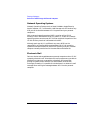
Workgroup Focus
Workgroup Focus
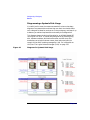
Most system administration manuals, including the HP-UX System
Administration Tasks manual in past releases, focus on single-system
tasks, telling you how to configure and maintain individual systems.
This is essential information, but it is not enough. These days, most
systems are not used in isolation; rather, computing resources are shared
across several systems: applications, files, databases, services such as the
World-Wide Web and mail, and peripherals such as printers, are usually
available to the users of more than one system and in some cases are
shared among hundreds or thousands of systems.
So common is the practice of sharing resources that the old way of
thinking of a system as a single “box” is often no longer useful; the
“system” a system administrator has to manage usually consists of at
least one server distributing resources over a LAN to at least five or six
clients, some of which in turn may share resources with each other. In
this document, we’ll refer to such interdependent systems as
workgroups, reserving the term system to mean a single “box.”
When so many major resources are shared, routine tasks such as
bringing a new system online, doing backups, updating software, adding
users and booting and shutting down systems, are all a little more
complex than they would be if the system existed in isolation.
For example, it is relatively simple task to shut down a standalone
system, but shutting down a file server without disrupting the work of
the users who depend on it requires some planning, and could require
work, such as copying the shared file systems to an alternative server
and copying them back before you bring the original server back online.
In addition, the new HP-UX operating system feature called OLA/R
enables the On-Line Addition and Replacement of PCI I/O cards, which
allows the administrator to add a new card and/or replace an existing
card without affecting other components of that system, other systems
connected to that workstation or requiring a reboot.
OLA/R concepts and procedures are presented in detail in the
Configuring HP-UX for Peripherals book.
This document provides simple, reliable guidelines and recipes for
managing such real-life tasks, while continuing to cover the basics of
single-system administration.
22
Chapter 1
Systems and Workgroups
How We Are Using the Terms “System” and “Workgroup”
How We Are Using the Terms “System” and
“Workgroup”
System
In this document, we use the term system to mean one HP-UX system, a
single “box”. A system so defined always has its own CPU (for example,
we do not refer to XTerminals as systems) but may or may not have its
own root file system.
See “Types of System” on page 24 for more information.
Workgroup
A workgroup is a group of systems that depend on a common server, or
servers, or on each other, for important services such as NFS-mounted
file systems, and whose users, in most cases, are working on joint
projects, or are in the same team or department.
A workgroup could also consist of a single, multiuser system to which
users log in from terminals or terminal-emulators, though such systems
are not the primary focus of this document.
In this first version of the document, workgroup means a grouping of
predominantly HP-UX systems, but you’ll find some information on
integrating Windows NT systems into such a workgroup.
See “Types of Workgroup” on page 26 for more information.
Chapter 1
23
Systems and Workgroups
Types of System
Types of System
Single-User versus Multiuser
For the purposes of this document, we’ll be distinguishing between two
ways for people to use a given system:
• as a single-user workstation, usually on someone’s desk and used
mainly or exclusively by that person;
• as a multiuser system, often kept in a computer room, with which
individual users communicate by means of a terminal, or
terminal-emulator on a desktop system connected by a LAN or
modem.
The power of stand-alone systems to handle more and more users (as
well as many other network functions) has grown dramatically.
For this reason, if you plan to set up a standalone machine as a
multiuser system, refer to the information regarding On-Line
Addition and Replacement in the Configuring HP-UX for Peripherals
book. This material can help you to plan your system set-up so that in
the event of certain hardware failure, you can replace the hardware
with little impact to the users.
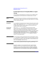
Server versus Client
Broadly speaking, a server supplies some kind of computing resource
(applications, files, compute cycles, printing and spooling...) and a client
uses that resource.
In this document, we’ll use the terms server and client most commonly,
although not exclusively, in the context of NFS (Networked File System)
services, and we’ll make that context clear wherever necessary by using
the terms NFS server and NFS client.
Under NFS, and in most other contexts, the same system can function as
both a server and a client. For example, a system may import one file
system (NFS-mounting it from another system’s disks) while exporting
another (allowing other systems to NFS-mount the file system from its
own disks). As an importer of one or more file systems, the system acts as
an NFS client; as an exporter, it acts as a an NFS server.
24
Chapter 1
Systems and Workgroups
Types of System
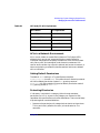
Hardware
The systems discussed in this document are mainly:
• HP 9000 Series 800 (usually referred to as “servers”)
• HP 9000 Series 700 (usually referred to as “workstations”)
• IBM-compatible personal computers (loosely referred to as “PC’s
Operating Systems
This document is for administrators of HP-UX systems, and the
workgroups we envisage are predominantly made up of such systems,
with some PC’s running Microsoft Windows NT.
Chapter 1
25
Systems and Workgroups
Types of Workgroup
Types of Workgroup
For the purposes of this document, a workgroup is group of
interdependent, predominantly HP-UX systems, but may also include
some Windows NT systems,
The HP-UX systems may or may not have their own root file systems.
See “NFS Diskless” on page 26, “Multiuser” on page 26 and
“Client-Server” on page 27.
NFS Diskless
Refers to workgroups, or portions of workgroups, that get the root of
their HP-UX file system from a remote server.
NOTE
NFS Diskless is supported on HP-UX 10.0 through 10.20. It is not
supported on HP-UX 10.30 or later.
While not ignoring such arrangements, this release of Managing Systems
and Workgroups: A Guide for HP-UX System Administrators pays more
attention to systems capable of booting from their own local disks (see
“Client-Server” on page 27).
For more information see:
• “NFS Diskless Model” on page 32
• “Setting Up and Administering an HP-UX NFS Diskless Cluster” on
page 633
Multiuser
A large (e.g., HP-UX V Class) system to which users log in via terminals
or terminal-emulators. These days, such systems often form part of a
“Client-Server” on page 27 workgroup in which at least some users have
their own desktop computers.
For more information see:
• “Multiuser Model” on page 30
26
Chapter 1
Systems and Workgroups
Types of Workgroup
• “Configuring a System” on page 113
• “Administering a System: Managing Disks and Files” on page 333
• “Administering a System: Managing Printers, Software, and
Performance” on page 465
Client-Server
For more information see:
• “Client-Server Model” on page 33
• “Configuring a Workgroup” on page 195
• “Administering a Workgroup” on page 595
Chapter 1
27
Systems and Workgroups
Types of Workgroup
28
Chapter 1
Planning a Workgroup
2
Planning a Workgroup
The topics that follow are primarily intended to help someone who is
about to set up a workgroup from scratch, but you may also find them
useful if you’re reconfiguring or expanding the workgroup.
If you need to know what we mean by workgroup, see “How We Are
Using the Terms “System” and “Workgroup”” on page 23.
Go to any of these topics for more information:
• “Choosing a File-Sharing Model” on page 30
• “Distributing Applications and Data” on page 36
• “A Sample Workgroup / Network” on page 42
• “Setting Disk-Management Strategy” on page 53
• “Planning to Manage File Systems” on page 60
• “Managing Users Across Multiple Systems” on page 79
• “Planning your Printer Configuration” on page 82
• “Distributing Backups” on page 101
• “Services for Data Exchange with Personal Computers” on page 103
• “Possible Problems Exchanging Data Between HP-UX and PCs” on
page 109
Chapter 2
29
Planning a Workgroup
Choosing a File-Sharing Model
Choosing a File-Sharing Model
If you are about to set up a new workgroup, or make large changes to an
existing one, you must first decide how you will distribute the computing
resources among the users. The biggest of these decisions concerns how
users will share files and applications. Will they:
• Log in to the system(s) on which the files and applications reside?
(“Multiuser Model” on page 30)
• Boot from a remote system and store shared data remotely? (“NFS
Diskless Model” on page 32)
• Boot from their local disk, but store shared files and applications
remotely? (“Client-Server Model” on page 33)
The answer is probably some combination of the above, and could
possibly be all of the above. The sections that follow are intended to help
you explore each model and choose a predominant one.
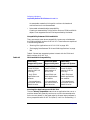
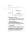
Multiuser Model
A multiuser system is a system to which a number of users log in to do
their work, using a terminal directly connected to the system, or a
terminal emulator on a remote system connected by a modem or LAN.
• “Advantages” on page 30
• “Disadvantages” on page 31
• “Summary” on page 31
Advantages
• May be the best use of the computing resources of a large system.
See “Distributing Applications” on page 38
• Simplest model:.
— Only one system to configure, back up and maintain.
— No operating-system co-existence issues.
— Simplest possible hardware/OS/application matrix.
• May reduce LAN traffic.
30
Chapter 2
Planning a Workgroup
Choosing a File-Sharing Model
• Security:
— Easy to protect physically (e.g, in a locked computer room).
— Allows you to keep sensitive data (or all data) off the desktop.
Disadvantages
• Large system required, possibly with multiple processors:
— Special power and climate requirements.
• Fragile:
— If system crashes, or is down for maintenance, no one works.
— Failure of any component likely to affect everyone.
• Inflexible:.
— Can’t easily redistribute load in response to changing (or
miscalculated) use and performance.
Summary
This model may be the right one for you if you have, or can afford to buy,
a high-powered system, and your users are all using the same
applications to manipulate data that can be stored centrally, not
parcelled out onto local disks. If this is the case, your users do not have to
forgo the advantages of windowing: XTerminals provide the same display
capabilities as workstation monitors.
Even if this model is not suitable in its pure form, you may well want to
use it in combination with a more distributed approach; for example, you
may want at least some of your users to have workstations on their
desks, but still allow them (or require them) to log in to a high-powered
“application server” to run applications that need the memory, MIPS,
disk space or other resources of a big system; or you might deploy your
applications across two or three high-end workstations and have users
log in to those to run them.
Chapter 2
31
Planning a Workgroup
Choosing a File-Sharing Model
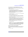
NFS Diskless Model
The term NFS Diskless describes systems that use special features of
NFS to share the root file system. (Diskless means that the clients do
not require a disk; in practice, many “diskless” workstations have at least
one disk). In this document, we use the term to refer specifically to the
HP implementation of NFS Diskless.
CAUTION
NFS Diskless is a good choice for workgroups, or portions of workgroups,
running 10.0 through 10.20, but it is not supported on later releases.
• “Advantages” on page 32
• “Disadvantages” on page 32
• “Summary” on page 32
• See also: Chapter 10, “Setting Up and Administering an HP-UX NFS
Diskless Cluster,” on page 633
Advantages
• Easy and efficient sharing of resources:
— Peripherals
— Disk space
• Single-point administration (via SAM).
• Physical security:
— Easy to keep valuable peripherals, and disks containing sensitive
data, in one central place and lock them up.
Disadvantages
• Not supported after HP-UX 10.20.
• Fragile:
— If the server crashes, or is down for maintenance, no one works.
• Heavily dependent on LAN and subnet performance:
— Swap to local disk recommended for best performance.
Summary
If you will be solely or mainly responsible for administering the
workgroup, and you do not need to run HP-UX 11.0, you should consider
NFS Diskless.
32
Chapter 2
Planning a Workgroup
Choosing a File-Sharing Model
This model has become less popular as the price of disk space has
declined, but is still the simplest way to administer a group of
workstations. SAM, the menu-driven System Administration
Manager, has been tailored as of HP-UX 10.01 to make it easy to
administer an NFS Diskless cluster from a single console. See Chapter
10, “Setting Up and Administering an HP-UX NFS Diskless Cluster,” on
page 633 for more information.
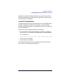
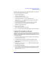
Client-Server Model
Client-server is an umbrella term we are using to refer to workgroups
that share resources other than the root file system; that is, the
workstations run HP-UX from their own local disks, but depend on an
NFS server for non-“system” files and applications, and may also have
common arrangements for printing, backups and user-access.
• “Advantages” on page 33
• “Disadvantages” on page 34
• “Summary” on page 34
Advantages
• Flexibility:
— Can easily redistribute resources in response to changing needs
and conditions and the results of trial-and-error.
• Robustness:
— Failure of one system or component will not necessarily affect
everyone.
— Data and other resources can often be switched quickly from a
failed system to a working one, minimizing downtime.
• Performance:
— By assigning roles such as file server, application server and
client, you should be able to deploy your hardware and software
resources for the best possible performance.
• Shared responsibility:
— Depending on your users, you may be able to turn over to them
most of the work of administering their own workstations,
reducing your workload in the long run.
Chapter 2
33
Planning a Workgroup
Choosing a File-Sharing Model
Disadvantages
• Complexity:
— Matrix of operating-system versions, application versions and
peripherals may be unwieldy.
— The more widely distributed the data, the harder it is to back up
— NFS mounts can create complex cross-dependencies between
systems; these can become hard to keep track of and pose
problems during boot and shutdown.
• Performance:
— Heavily dependent on LAN and subnet performance.
— Running applications locally may alleviate LAN bottlenecks, but
at the cost of losing the computing power of a large server.
• Disorganization:
— If users are even partially free to administer their own systems,
complexity, and unexpected problems, may increase beyond your
power to manage them.
Summary
Because of its flexibility, and perhaps also because it seems to many
people a natural way to arrange things, this model is increasingly
popular, and this document devotes much of its space to it.
In theory, this model allows you to have the best of all worlds; everyone
in the workgroup can use the best combination of the group’s resources compute power, mass storage, printing, display capabilities - without
being so dependent that they all have to go home if a server goes down.
In practice, there are difficult trade-offs. If you want everyone to send
and receive their mail locally, for example (rather than depend on a mail
hub) you will have to configure and maintain mail alias files on each
workstation, a lot of work in a large organization. If you want to reduce
LAN traffic by having people run applications and store data locally, you
will not only have to arrange to back up that data, but may also find
yourself buying disks and memory to get acceptable local performance.
On the other hand, consolidating resources on servers should save you
time and money, but it leads you back toward a mainframe-like
dependency on a few systems, with an additional dependency on the
performance and reliability of the LAN.
34
Chapter 2
Planning a Workgroup
Choosing a File-Sharing Model
If you adopt this model, you should allow some time (and if possible,
some of your budget) for trial and error and refinement. “Distributing
Applications and Data” on page 36 some guidelines and suggestions.
Chapter 2
35
Planning a Workgroup
Distributing Applications and Data
Distributing Applications and Data
The topics that follow are intended to help you plan the overall
configuration of the workgroup, in terms of what pieces of the workflow
reside and run on what systems. This section will make better sense if
you have already read “Choosing a File-Sharing Model” on page 30; you
will notice that the discussion is biased towards the “Client-Server
Model” on page 33.
Go to any of the following for more information:
• “HP-UX File-Sharing Model (V.4)” on page 36
• “What To Distribute; What To Keep Local” on page 37
• “Servers for Specific Purposes” on page 39
HP-UX File-Sharing Model (V.4)
HP-UX introduced a new file-system layout at 10.0. The new layout is
based on the AT&T SVR4 and OSF/1 file systems and is intended to
provide benefits such as:
• the separation of operating system software from application
software
• a foundation for file-sharing models such as “NFS Diskless Model” on
page 32 and “Client-Server Model” on page 33
• consistency with other UNIX vendors
See the HP-UX 10.0 File System Layout White Paper on
http://docs.hp.com for more information.
How Does this Help You Share Files?
The new layout is cleaner and more logical than 9.x, it is essential for
NFS Diskless (see “NFS Diskless Model” on page 32), and it should
make interoperating with other vendors’ UNIX systems simpler.
It doesn’t change the mechanics of configuring NFS mounts, but it does
make managing them easier in one important respect: the segregation of
non-“system” applications under /opt, and the changes applications
such as Netscape have made to comply, mean that the server can now
36
Chapter 2
Planning a Workgroup
Distributing Applications and Data
export a given application from a single subdirectory under /opt, rather
than having to export several subdirectories for each application, or even
the whole of /usr/local.
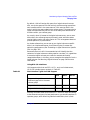
What To Distribute; What To Keep Local
Theory
The V.4 file-sharing paradigm divides HP-UX directories into two
categories: private and shared (sometimes also referred to as dynamic
and static).
Directories that contain a system’s configuration information are
designated private and should not be shared via NFS.These are:
• /
(root)
• /etc
• /dev
• /var
• /stand
The model also defines /home (for users’ home directories), /tmp and
/mnt (for local mounts) as private, though in practice there is an
argument for sharing /home and /var/mail (see “Should You Share
Users’ Home and Mail Directories?” on page 80) In addition,
/opt itself should not be shared, though its subdirectories are prime
candidates for sharing.
Directories defined as sharable are:
• /usr
• /sbin
• subdirectories of /opt
Practice
In practice, except under NFS Diskless (see “NFS Diskless Model” on
page 32) it is not a good idea to share /sbin or directories under /usr
other than /usr/local because it creates too much dependency (the
NFS client cannot function unless the NFS server is up) and because it
will cause problems when you try to upgrade the systems to a new
Chapter 2
37
Planning a Workgroup
Distributing Applications and Data
HP-UX release. HP recommends you implement such tightly coupled
configurations only under NFS Diskless (currently restricted to 10.x
systems).
Directories you should consider sharing are:
• application directories under /opt
• directories that hold the data on which the shared applications
operate
• directories that hold projects on which a number of users are
collaborating
• directories that hold important, volatile data that must be backed up
nightly
For example, the authors of this document keep the source text on a file
server, a Series 800 system running HP-UX 10.20, which is backed up
nightly. Our authoring tools and our web browser reside on an
application server, a K-class server running 10.20, on which all software
maintenance is done. Our local disks are not backed up and house no
applications or tools that require outside support.
Distributing Applications
The main criteria here are performance and ease of management. The
practical possibilities are:
• store them on a server and distribute them to the workstations via
NFS
• store them on a server to which users log in to run them
The only configuration you should probably rule out from the beginning
is to install each application individually on each workstation’s local
disks; this might make sense for the occasional individual user with
special needs, but software management considerations make it almost
unthinkable as a general approach.
Given that you will store applications on a server or servers, is it better
to run them on the workstations (via NFS) or on the server? Opinions are
divided, and in practice you may well mix the two approaches. But bear
in mind that modern applications are swap- and memory-intensive; it is
often better to concentrate these resources on a server than to parcel
them out to individual workstations.
38
Chapter 2
Planning a Workgroup
Distributing Applications and Data
For the greatest ease of management (backups and software
maintenance) you should:
• keep data in one central place where it can be easily backed up
• maintain only one version and one copy of each application
• if possible, concentrate applications on a single, powerful server
Aim for the simplest configuration that is consistent with acceptable
performance.
Servers for Specific Purposes
The useful part of any computer system consists of applications and the
data they manipulate. Your task is to decide how to deploy the
workgroup’s applications and data so that they are adequately
accessible, responsive, and secure.
This section assumes that:
• you are going to put workstations (as opposed to display terminals
only) on at least some users’ desks
• the workgroup users will share at least some of the same
applications.
You should plan to keep shared applications in a central location where
you install, configure, back up and maintain them. Similarly, you should
plan to keep all data that users share, and as much volatile data as
possible (that is, data that changes frequently, whether or not it is shared
by more than one user) in a central location where you can back it up
easily, and from where it is distributed to the workstations via NFS.A
system whose disks hold shared data is normally called a file server
(even if the data actually resides in databases rather than ordinary files).
A system on which shared applications are stored might be called an
application server or a compute server; we’ll use application server.
In many workgroups, the file server and the application server are the
same machine, which is simply a warehouse for everything that is shared
and everything that needs to be backed up regularly. This may be
convenient, and it may be the best you can do with the available
hardware, but it is not ideal because the functions of a file server are
different from those of an application server and may interfere with
them: for example a CPU that is busy handling NFS requests will have
fewer cycles for running applications.
Chapter 2
39
Planning a Workgroup
Distributing Applications and Data
File Server
Users normally do not log in to a file server; they get the data they need
from it by means of NFS mounts.
The main requirements for a file server are:
• plenty of disk space
Disk striping, which allows I/O to multiple spindles concurrently, may
improve throughput.
• plenty of RAM
• fast I/O interfaces such as Fast-Wide SCSI.
• proximity to the workstations it serves
Intervening hubs, routers, switches and busy LAN segments will slow
things down.
This list is not meant to imply that CPU power is not important in a file
server, only that it is not as important as it is in application server.
Application Server
If you have, or can afford to buy, the hardware resources, you should
install applications on a system to which users can log in and run them.
Whether they do or not will depend partly on how much power and
capacity they have on their desktops, partly on LAN performance, partly
on OS/application compatibility; but it’s likely that at least some users in
the group will not be able to run all the applications they need locally,
and others will prefer not to because, for one reason or another, local
performance is poor. And of course some applications, such as large
database applications, by their nature require capabilities not likely to
be found on anyone’s desktop.
An application server, then requires:
• All the characteristics of a file server, because in some cases it acts as
a file server, distributing applications via NFS to clients that run
them locally.
For performance reasons, this is probably not an ideal arrangement
(the applications are likely to run faster if the server’s CPU is not
busy handling NFS requests) but it’s a common one, and in practice it
may work well.
40
Chapter 2
Planning a Workgroup
Distributing Applications and Data
• In addition, a powerful processor, and possibly multiple processors, so
that it can run large applications, and many applications
concurrently.
For reasons of application compatibility, an application server may also
need more frequent operating-system updates than a file server.
Chapter 2
41
Planning a Workgroup
A Sample Workgroup / Network
A Sample Workgroup / Network
To provide consistency among the case studies and examples throughout
Managing Systems and Workgroups: A Guide for HP-UX System
Administrators (MSW), we have developed a sample workgroup/network
to demonstrate a variety of situations and tasks.
While it is impossible to account for every possible combination of
equipment and network topography, we have tried to account for many
common configurations.
The MSW Network (Overview)
The MSW network has two “subnets”, joined at a gateway computer that
has two networking interface cards in it. The subnets, known as “net1”
and “net2,” use Internet Protocol (IP) addresses in the following ranges:
net1 15.nn.yy.0 through 15.nn.yy.256
net2 15.nn.xx.0 through 15.nn.xx.256
NOTE
The IP addresses used in the example network and throughout MSW are
designated using the nonspecific address components “nn”, “xx”, and “yy”
to avoid conflicting with real-world IP addresses. IP addresses do not
normally contain letters.
Throughout this book, subnets net1 and net2 are part of a generic
domain called “corporate”.
Figure 2-1 on page 43 shows an overview of the example network for
Managing Systems and Workgroups. The section “The MSW Network
(System by System)” on page 44 gives detailed information about the
systems in the example network.
42
Chapter 2
Planning a Workgroup
A Sample Workgroup / Network
Figure 2-1
Managing Systems and Workgroups Example Network Diagram
15.nn.yy
15.nn.xx
Server Model K450
(flserver)
Server Model K260
(appserver)
W/S Model 715
(ws715)
W/S Model 710
(ws710)
Network Hub
W/S Model B132L
(ws132)
HP Vectra VA (PC)
(pcvect1)
Network
Printer (netlp1)
Network
Printer (netlp2)
HP Vectra VA (PC)
(pcvect2)
Thin Client
(tc150)
Chapter 2
W/S Model 712/100
(ws712)
Thin Client
(tc151)
43
Planning a Workgroup
A Sample Workgroup / Network
Table 2-1
Managing Systems and Workgroups Example Network
Server
Systems
Workstations
Personal
Computers
(PCs)
Thin Clients
Network
Printers
flserver
ws132
pcvect1
tc150
netlp1
appserver
ws710
pcvect2
tc151
netlp2
ws712
ws715
The MSW Network (System by System)
The MSW network includes a variety of system types: server systems,
workstations, personal computers, and thin clients. There are also
several network-based printers. For details on the specific systems listed
in the preceding table, review the following descriptions until you find
the system that interests you.
Server Systems
hp
Hewlett
Packard
The MSW example network includes two server systems:
44
Chapter 2
Planning a Workgroup
A Sample Workgroup / Network
appserver
This system, an HP9000 Model K260, is an
applications server in the example network. Master
copies of software are stored here and run from other
computers in the network. It is running HP-UX
Release 11.0 in 64-bit mode (32-bit compatible).
flserver
This system, an HP9000 Model K450, is one of the key
computers in the network. Its name reflects its primary
use, a file server. It is where this workgroup stores
most of its data. For this reason it is equipped with a
lot of disk space.
In addition to its use as a file server, it is also the
gateway computer between the two subnets net1 and
net2. It has two network cards, one connecting to net1
via thin-lan coaxial cable, and one connecting to net2
via a 10-BaseT network hub.
flserver also has a printer directly connected to it.
appserver
System Name:
appserver.net2.corporate
System Type:
HP 9000 Model K260
Network (IP) Address:
15.nn.xx.200
Operating System:
HP-UX Release 11.0
(64-bit mode)
Physical Memory:
1 GB
Disk Space:
16 GB
Features:
Application Server for Workgroup
This is the one computer and
operating system combination in the
workgroup capable of running in
64-bit mode, and it contains the
largest amount of physical memory it
can hold to take full advantage of the
64-bit operating mode.
flserver
System Name:
flserver.net1.corporate
flserver.net2.corporate
System Type:
Chapter 2
HP 9000 Model K450
45
Planning a Workgroup
A Sample Workgroup / Network
Network (IP) Addresses:
15.nn.yy.100 (on subnet “net1”)
15.nn.xx.100 (on subnet “net2”)
Operating System:
HP-UX Release 10.20
Physical Memory:
1 GB
Disk Space:
48 GB
Features:
File Server for Workgroup.
This is the computer that stores most
of the data files for the workgroup
represented in MSW. It is a large,
LVM configuration with high
availability features installed.
This computer is the gateway system
between the subnets net1 and net2.
Because of that it has two network
names (flserver.net1 and
flserver.net2) and two IP
addresses (one for each network
interface card).
Workstations
hp
hp
Hewlett
Packard
HewlettPackard
PA-RISC
Powered
Model 715/100
There are four workstations in the MSW example network, one on the
net1 subnet, the others on net2. Each is a different model, and they run
different versions of HP-UX to reflect many installations in the real
world where not every computer is running the same HP-UX release.
46
Chapter 2
Planning a Workgroup
A Sample Workgroup / Network
ws710
ws712
ws715
ws710
This is the workstation connected to the net1 subnet.
It is running an older version of HP-UX in the network,
HP-UX Release 10.01.
ws712
An HP9000 Model 712/100 running HP-UX Release
11.0.
ws715
An HP9000 Model 715/100 running HP-UX Release
10.01
ws132
An HP9000 Model B132L running HP-UX Release
11.0.
System Name:
ws710.net1.corporate
System Type:
HP 9000 Model 710
Network (IP) Address:
15.nn.yy.101
Operating System:
HP-UX Release 10.01
Physical Memory:
32 MB
Disk Space:
2 GB
Features:
Computer in the workgroup running
an older version of HP-UX operating
system.
System Name:
ws712.net2.corporate
System Type:
HP 9000 Model 712/100
Network (IP) Address:
15.nn.xx.103
Operating System:
HP-UX Release 11.0 (32-bit mode)
Physical Memory:
19 MB
Disk Space:
6 GB
Features:
Software development workstation
running HP-UX Release 11.0 in
32-bit mode
System Name:
ws715.net2.corporate
System Type:
HP 9000 Model 715/100
Network (IP) Address:
15.nn.xx.101
Chapter 2
47
Planning a Workgroup
A Sample Workgroup / Network
Operating System:
HP-UX Release 10.01
Physical Memory:
64 MB
Disk Space:
4 GB
Features:
ws132
System Name:
ws132.net2.corporate
System Type:
HP 9000 Model B132L
Network (IP) Address:
15.nn.xx.102
Operating System:
HP-UX Release 11.0
Physical Memory:
128 MB
Disk Space:
6 GB
Features:
Personal Computers (PCs)
hp
Hewlett
Packard
The MSW example network includes two HP Vectra VA PCs, each
running the “Microsoft Windows NT 4.0 Workstation” operating system.
pcvect1
48
This HP Vectra VA personal computer is located on the
net1 subnet.
Chapter 2
Planning a Workgroup
A Sample Workgroup / Network
pcvect2
pcvect1
This HP Vectra VA personal computer is located on the
net2 subnet.
System Name:
pcvect1.net1.corporate
System Type:
HP Vectra VA
Network (IP) Address:
15.nn.yy.3
Operating System:
Microsoft Windows NT Workstation
4.0
Physical Memory:
32 MB
Disk Space:
2 GB
Features:
pcvect2
System Name:
pcvect2.net2.corporate
System Type:
HP Vectra VA
Network (IP) Address:
15.nn.xx.2
Operating System:
Microsoft Windows NT Workstation
4.0
Physical Memory:
32 MB
Disk Space:
4 GB
Features:
Chapter 2
49
Planning a Workgroup
A Sample Workgroup / Network
Thin Clients
The MSW example network also includes two HP Entria Plus thin client
computers. These devices have no disks of their own and are highly
dependent on other computers in the network to boot and run. They boot
from a host computer using the bootp protocol.
tc150
tc150
An HP Entria Plus thin client computer.
tc151
An HP Entria Plus thin client computer.
System Name:
tc150.net2.corporate
System Type:
HP Entria Plus Network Computer
Network (IP) Address:
15.nn.xx.150
Operating System:
HP Enware 7.0 / HP-UX (release
varies - see features)
Physical Memory:
8 MB
Disk Space:
<none>
Features:
HP Enware is the core software
running this Entria Plus thin client,
the client then boots via the bootp
50
Chapter 2
Planning a Workgroup
A Sample Workgroup / Network
protocol from an HP-UX server
somewhere in the
network/workgroup. The Entria Plus
then depends on the HP-UX system
for running programs, etcetera.
tc151
System Name:
tc151.net2.corporate
System Type:
HP Entria Plus Network Computer
Network (IP) Address:
15.nn.xx.151
Operating System:
HP Enware 7.0 / HP-UX (release
varies - see features)
Physical Memory:
16 MB
Disk Space:
<none>
Features:
HP Enware is the core software
running this Entria Plus thin client,
the client then boots via the bootp
protocol from an HP-UX server
somewhere in the
network/workgroup. The Entria Plus
then depends on the HP-UX system
for running programs, etcetera.
Network Printers
The MSW network also contains several network printers, one on each
subnet.
netlp1
netlp2
Printer Name:
netlp1.net1.corporate
Printer Type:
HP Color LaserJet 5
Network (IP) Address:
15.nn.yy.11
Features:
Equipped with an HP JetDirect
network card for direct network
connections.
Printer Name:
netlp2.net2.corporate
Printer Type:
HP LaserJet 5si MX
Network (IP) Address:
15.nn.xx.10
Chapter 2
51
Planning a Workgroup
A Sample Workgroup / Network
Features:
52
Equipped with an HP JetDirect
network card for direct network
connections.
Chapter 2
Planning a Workgroup
Setting Disk-Management Strategy
Setting Disk-Management Strategy
This section covers:
• “Distributing Disks” on page 53
Which systems should you attach the workgroup’s disks to?
• “Capacity Planning” on page 54
How much disk space do you need?
• “Disk-Management Tools” on page 56
LVM, mirroring, striping - what are they and what are they for?
Distributing Disks
Read these guidelines in conjunction with “Distributing Applications and
Data” on page 36.
• Concentrate file system capacity on file and application servers.
A workgroup in which every system is sufficient unto itself is an
administrator’s nightmare. The desktop is a bad place to store:
— Applications (unless the user takes explicit responsibility for
maintaining them).
— Data (except data that does not need to be backed up).
• Make sure each workstation has a local disk.
Even a “diskless” client needs sufficient local disk space to swap
locally. NFS Diskless (available on some 10.x systems) does allow
clients to swap to a server’s disks, but performance probably won’t be
acceptable.
• Ideally, put data and applications on separate servers, so that the file
server’s CPU is occupied mainly with processing NFS requests, while
the application server runs applications.
Chapter 2
53
Planning a Workgroup
Setting Disk-Management Strategy
Capacity Planning
As with memory, the simple answer to the question, “How much disk
capacity should you buy?” is “As much as you can afford.” You can almost
guarantee that however much capacity you buy now, your users and
their applications will find a way to exhaust it within a year.
All the same, you need to plan. Even if you are equipping your
workgroup from scratch, and the team of users is being formed from
scratch, it’s likely that the work the team will be doing has not just been
invented; somewhere in your company the same or similar work is being
done, and that’s where you need to start.
File and Application Servers
File Systems and Databases
• What applications are your users currently using, or, if this is a
start-up project, what applications are currently being used for
comparable tasks by about the same number of users?
• How much disk space is being used by the applications themselves?
• How much space is being used by the data directories the applications
read and write to?
• How much space are your users (or comparable users) currently
consuming in their home and mail directories?
The answers to these questions will give you a starting point for
determining how much disk space to allow in the non-“system” volumes
of your file and application servers - that is, in the application (/opt),
work, mail and home directories and in the database volumes.
It will not hurt to allow for 100% growth in the first year in these
directories (or more than that if you if you do not plan to control the
growth of user directories with disk quotas - see “Managing Disk Space
Usage with Quotas” on page 391). During the year you can monitor
actual growth and plan next year’s purchases accordingly.
Swap
There is no standard way for estimating swap, except that swap must be
at least equal to the memory of the local system. This may be sufficient
for clients; it almost certainly will not be for servers.
54
Chapter 2
Planning a Workgroup
Setting Disk-Management Strategy
“Managing Swap and Dump” on page 425 provides some guidelines for
estimating swap needs, but there is often no substitute for running the
applications and seeing what happens.
Example
Here’s what we did to figure out how much swap would be used by the
tools used to develop this document.
We booted a workstation (an HP9000 715 running HP-UX 10.01 with
96MB RAM), started up VUE, opened one window, then started up all
the applications one after another, using swapinfo (1M) to check swap
usage each time.
CAUTION
The numbers that follow represent what happened on a given system on
a given day; we are recording them only to illustrate the method. They in
no way define the performance of the products or of HP-UX.
Running HP-UX at run-level 3 took 19-20 MB of reserved swap.
Transitioning to run-level 4 and opening one VUE window brought us up
to 39-40 MB of reserved swap; this is shown in the first row of the table;
subsequent rows show what happened as we started up the applications.
Totals in the right-hand column are cumulative.
Table 2-2
Sampling Swap Usage
Reserved/Used
on Creation
(MB)
Activity
HP-UX/VUE
39-40
0
Open 1
window
FrameMaker
10
0
Open
document
emacs
2
0
DynaText
browser
4
0
Open
book
1
0
60
Netscape
6
0
Load
graphic
1
0
67
Chapter 2
Additional MB
Reserved/Use
d
Total
Run...
39-40
1
2
53
55
55
Planning a Workgroup
Setting Disk-Management Strategy
We repeated the experiment on another, much smaller system (32 MB
RAM) and got similar results, drawing the conclusion that a workstation
running these applications locally would need to have about 30 MB of
swap available, for a minimum of 70 MB configured swap.
In our particular situation, since we didn’t have a powerful application
server at the time, and did have several moderately powerful
workstations, we decided it made sense for us to import these
applications onto the workstations (via NFS mounts from our file server),
and accordingly we added file-system swap to those systems that looked
as if they would need it.
If you were to run such an experiment on a multiuser application server,
you would need to run as many copies of each application as would
actually be running at peak times, and would need to be a good deal less
simple-minded than we were in terms of the functions the applications
performed and the frequency and complexity of the samples.
Workstations
A workstation needs enough space on the local disk to hold the operating
system, plus sufficient swap for the workspace manager and whatever
applications will be running locally.
Plan on providing each workstation with at least a 1 GB disk. Both
HP-UX and NT workstations may be able to get by with 500 MB, but
barely, particularly if some sizeable applications are running locally (via
NFS or from the local disk); see “Swap” on page 54.
Disk-Management Tools
This section provides a brief summary of the disk-management tools
HP-UX provides; for details see “Administering a System: Managing
Disks and Files” on page 333.
Logical Volume Manager (LVM)
LVM is the most common disk-management method for current versions
of HP-UX on all platforms. As of release 10.20, it is the default on Series
800 systems (except those installed with a root disk smaller than 1GB),
and is required on Series 700 systems whose root disk is larger than
2GB.
56
Chapter 2
Planning a Workgroup
Setting Disk-Management Strategy
LVM divides up the disk in much the same way as the “hard partitions”
implemented under earlier versions of HP-UX for the Series 800, but
logical volumes are very much easier to reconfigure than partitions, and
they can span two or more disks. These two attributes make LVM a
much more powerful and flexible tool than hard partitions.
NOTE
The VERITAS Volume Manager is available for HP-UX beginning with
HP-UX 11i. It is on the HP-UX 11i Application CD. The VERITAS
Volume Manager provides state-of-the-art online disk management and
is an alternative to the HP Logical Volume Manager and HP
MirrorDisk/UX products. See the HP VERITAS Volume Manager 3.1
Release Notes on http://docs.hp.com for more information.
“Whole Disk”
The alternative to LVM is “whole-disk” management, which as the name
implies treats the disk as a single unit.
Should You Use LVM or “Whole Disk”?
Advantages of LVM:
• Logical volumes can span multiple disks:
— File systems (and individual files) can be larger than a single
physical disk.
— A logical volume can be as small or large as the file system
mounted to it requires.
— Space need not be wasted: small chunks of unused space from
several disks can be combined to create a usable volume.
• You can extend a file system without rebuilding it.
— Reducing a file system is more complex, but is also relatively
painless.
• LVM supports “Disk Mirroring” on page 58 and “Disk Striping” on
page 58.
Disadvantage of LVM:
• Complexity.
Chapter 2
57
Planning a Workgroup
Setting Disk-Management Strategy
LVM is a sophisticated tool; as such, it takes time to learn, it requires
maintenance (configuration information needs to be backed up) and
things can go wrong (if configuration information is lost or corrupted,
there may be no way to get to the actual data on the disk, even though
this data may itself be intact).
But, your LVM configuration is automatically backed up every time
you change it (in /etc/lvmconf), and “Disk Mirroring” on page 58
provides insurance against data loss that is not available under the
“whole-disk” method.
You should certainly use LVM on file and application servers; on
workstations that have only a single disk, used only to store the
operating system and for swap, LVM is not necessary, though you may
choose to implement it anyway for the sake of uniformity, or because you
expect to add more disks to some workstations over time.
Disk Mirroring
Disk mirroring is available only under LVM. See “Logical Volume
Manager (LVM)” on page 56.
Disk mirroring allows you to keep a live copy of any logical volume; the
data in that volume is in effect being continuously backed up. Strict
mirroring ensures that the mirror copy is on a separate disk (in the
same volume group).
Disk mirroring has the obvious advantages of increased data protection
and system availability, and the equally obvious disadvantage of
consuming twice as much disk space (or as many times more as there are
mirror copies). Use disk mirroring for volatile, mission-critical data; you
do not need to mirror volumes containing static software such as the
operating system.
Disk Striping
Disk striping is available only under LVM. See “Logical Volume Manager
(LVM)” on page 56.
Disk striping distributes logically contiguous data blocks (for example,
chunks of the same file) across multiple disks. This speeds I/O
throughput for large files when they are read and written sequentially
(but not necessarily when access is random).
58
Chapter 2
Planning a Workgroup
Setting Disk-Management Strategy
The disadvantage of disk striping is that the loss of a single disk can
result in damage to many files, since files are purposely spread piecemeal
across two or more disks.
Consider using disk striping on file systems where large files are stored,
if those files are normally read and written sequentially and I/O
performance is important.
Chapter 2
59
Planning a Workgroup
Planning to Manage File Systems
Planning to Manage File Systems
This section addresses questions you might have when planning to
administer file systems. The following topics are discussed:
• “Introduction to Managing File Systems” on page 60
• “File System Limits of HP-UX Releases” on page 61
• “Determining What Type of File System to Use” on page 62
• “File System Wrappers” on page 63
• “Journaled File System, the New File System Default” on page 63
• “Frequently Asked Questions about the Journaled File System” on
page 64
For procedures used to administer file systems, go to “Managing File
Systems” on page 373.
Introduction to Managing File Systems
System files, application files, and user files all must reside in a file
system to be available to the operating system and applications.
The overall HP-UX file system consists of a directory tree or hierarchy,
starting from the root. Although the file system may appear as one
unitary system, it may actually consist of several different “pieces”, each
stored on different devices or on different logical volumes. To enable
users to access the files in a file system, except for the root file system,
you must “mount” the file system. This can be done either manually or
automatically at boot-up, by attaching it to a directory in the existing
directory tree. The directory where you attach the added file system is
called the mount point.
• For procedural information, go to “Mounting File Systems” on page
376.
• For information helpful in selecting JFS mount options, go to “JFS
and the mount Command” on page 71.
You can also unmount a file system, and if you choose, re-attach it at a
different mount point.
60
Chapter 2
Planning a Workgroup
Planning to Manage File Systems
For procedural information, go to “Unmounting File Systems” on page
380.
There are a variety of reasons why you might create a new piece of the
overall file system, including:
• You have just added a new non-LVM disk or logical volume.
• You are concerned about the possibility of running out of disk space
for your users’ files (or you actually have run out of disk space).
• You wish to separate portions of a file system physically, either to
restrict growth of files within a portion of the file system or to
increase access speed for better performance. For example, you may
wish to keep the root file system as small as possible for performance
and security reasons. Or, you may wish to provide for a distinct group
of users and their needs, or to separate certain data with distinct
characteristics.
• You wish to replace a larger file system within a non-LVM disk or
logical volume with a new smaller one. This may require that you
create a new file system within that non-LVM disk or logical volume.
For procedural information, go to “Creating a File System” on page
374.
File System Limits of HP-UX Releases
10.01
10.10
10.20
32-bit and
64-bit 11.x
JFS 3.1 / 3.3
File System
4 GB
128 GB
128 GB
1 TB
File Size
2 GB
2 GB
128 GB local,
2 GB network
1 TB
Physical RAM
2 GB
3.75 GB
3.75GB
4 TB
Shared Memory
1.75 GB
1.75 GB
2.75 GB
8 TB
Process Data Space
0.9 GB
1.9 GB
1.9 GB
4 TB
Number of File Descriptors
2K
60 K
60 K
60 K
Number of User IDs
60 K
60 K
~2,000 K
~2,000 K
Chapter 2
61
Planning a Workgroup
Planning to Manage File Systems
Determining What Type of File System to Use
As of HP-UX 11.0, the Journaled File System (JFS) is installed as the
default for root and other HP-UX file systems. However, beginning at
HP-UX 10.01, four other file-system types are available for use on
HP-UX. Information on each is presented in the following table:
Table 2-3
HP-UX File System Types
File System
Type
When Should I Use It?
Additional Information
JFS (Journaled
File System)
Installed by default for
HP-UX 11.0. Recommended
for general purposes.
HP-UX implementation of a journaled
file system (JFS). Provides fast file
system recovery and the ability to
perform a variety of administrative
tasks online.
HFS (High
Performance
File System)
When you need
compatibility with earlier
HP-UX releases.
Represents HP-UX standard
implementation of the UNIX File
System (UFS).
NFS (Network
File System)
Use NFS to mount
directories from remote
systems.
NFS allows many systems to share the
same files by using a client/server
approach. Since access techniques are
transparent, remote file access appears
similar to local file access.
CDFS
(CD-ROM File
System)
Use CDFS to mount a
CD-ROM containing a file
system.
CDFS is a read-only file system; you
cannot write to a CDFS.
LOFS
(Loopback File
System)
Use LOFS to mount an
existing directory onto
another directory.
Allows the same file hierarchy to appear
in multiple places, which is useful for
creating copies of build and
development environments.
It is permissible to have a mixture of JFS and other file systems on a
single computer system.
62
Chapter 2
Planning a Workgroup
Planning to Manage File Systems
NOTE
Access Control Lists are supported in JFS beginning with JFS 3.3, which
is included with HP-UX 11i. You can obtain JFS 3.3 for HP-UX 11.00
from the HP Software Depot, http://software.hp.com.
To see if JFS 3.3 is installed on an HP-UX 11.00 system, run
swlist -l fileset JFS
If JFS 3.3 is installed, the output will include a list of JFS filesets. If you
get an error message, JFS 3.3 is not installed.
File System Wrappers Many file system administration commands
now provide a -F FStype option that allows you to specify the file
system type. Use the following keywords to indicate the appropriate file
system type:
• vxfs for JFS (VxFS)
• hfs for HFS
• nfs for NFS
• cdfs for CDFS
• lofs for LOFS
HP-UX can determine the file system type for commands that operate on
a pre-existing file system, even if -F FStype is not specified on the
command line.
For further information on file system wrappers, see fs_wrapper (5).
For procedural information on file system conversion, see “Converting
Existing File Systems to JFS” on page 408.
Journaled File System, the New File System Default
JFS is the HP-UX implementation of the VERITAS journaled file system
(VxFS), which features superb reliability and fast recovery. As of release
10.30, JFS is the default HP-UX file system. HP-UX 11i includes JFS
3.3.
Chapter 2
63
Planning a Workgroup
Planning to Manage File Systems
Basic JFS functionality is included with the HP-UX operating system
software. With the installation of a separately orderable product called
HP OnLineJFS (product number B3929CA for servers, B5118CA for
workstations), JFS also provides online administrative operations,
including backup, resizing, and defragmentation.
The advantages of JFS are well worth the small amount of learning
required to use it.
For procedural information pertinent to JFS file systems, go to:
• “Converting Existing File Systems to JFS” on page 408
• “Resizing a JFS File System” on page 416
• “Defragmenting a JFS File System” on page 407
• “Dealing with File System Corruption” on page 384
• “Backing Up a JFS Snapshot File System” on page 456
NOTE
For additional information about JFS capabilities, see Disk and File
Management Tasks on HP-UX, published by Prentice Hall. Also see HP
JFS 3.3 and HP OnLineJFS 3.3 VERITAS File System 3.3 System
Administrator’s Guide, available on http://docs.hp.com.
Frequently Asked Questions about the Journaled File
System
What is JFS?
JFS is the HP-UX implementation of the VERITAS journaled file system
(VxFS) introduced in HP-UX 10.01. It features high reliability, fast
recovery, and online administrative operations, including backup,
resizing and defragmentation.
For how long has JFS been available in HP-UX?
HP phased in the implementation of JFS over several releases:
• HP-UX 10.01 introduced an initial porting of JFS, based on VERITAS
Version 2 VxFS, for mountable (but not root) file systems. Until then,
HFS (high-performance file system) was the only locally mounted
read/write file system available.
64
Chapter 2
Planning a Workgroup
Planning to Manage File Systems
• As of 10.20, HP-UX allowed JFS as a local root file system within a
logical volume, although not on a non-partitioned, whole disk. The
10.20 implementation of JFS is VERITAS Version 3, which supports
file sizes greater than 2 GB as well as large user identification
numbers (UIDs). See vxupgrade (1M) for information to convert a
Version 2 file system to Version 3. You are not restricted to using only
a single version on your system; however, you cannot mount Version 3
on a 10.01 system.
• As of 10.30, JFS became the default file system for Instantly Ignited
and cold installed servers.
• HP-UX 11i includes JFS 3.3, which supports Access Control Lists
(ACLs) and disk layout Version 4, among other features. HP-UX 11.00
includes JFS 3.1, but JFS 3.3 is available for HP-UX 11.00 from the
HP Software Depot, http://software.hp.com.
JFS and other File Systems
How does the journaled file system (JFS) compare to HFS?
JFS improves upon the High-Performance file system (HFS) in the
following ways:
• faster recovery time versus HFS fsck, by using an intent log
• more robust than HFS, because JFS contains more panic avoidance
code
• better performance under many circumstances, due to use of extents
• online administration, including backups, resizing, and
defragmentation, using the optional HP OnLineJFS package
As compared to HFS, JFS recovers much faster from system failure, due
to its mechanism for logging changes to the file-system structure. When
the system boots after a crash, the file system synchronizes using its log
to speed recovery, in an operation similar to, but much faster than, that
performed by fsck. Fast recovery time is particularly useful in
environments that require high performance or that deal with large
volumes of data.
JFS allows for higher data throughput (faster I/O) than HFS. This is due
to the JFS organization of file storage into extents, which can consist of
multiple data blocks.
Chapter 2
65
Planning a Workgroup
Planning to Manage File Systems
The optional HP OnLineJFS product eases system maintenance by
allowing you to perform tasks such as file-system backup and enlarging
or reducing a file system without unmounting it. These capabilities are
not available on HFS.
• “Converting Existing File Systems to JFS” on page 408
What are the disadvantages of configuring a file system using JFS?
You might not want to configure JFS on a system with limited memory
because its memory requirements exceed those of HFS.
Is JFS use restricted in any way by LVM (see “The Logical Volume
Manager (LVM)” on page 335)?
You can use JFS on any file system, whether or not it is being managed
by LVM.
How is JFS administered?
JFS can be administered using SAM or HP-UX commands. SAM has
utilities to create (add), backup, and resize JFS file systems.
If you have the optional HP OnLineJFS package (referred to in some
manpages as Advanced VxFS), you can use the VxFS Maintenance menu
choice of SAM to view extent and directory fragmentation, reorganize
extents and directories, resize JFS file systems while online, and perform
an online backup using a snapshot of a JFS file system.
From the command line you can use:
• mkfs -F vxfs command to create a JFS file system (see mkfs_vxfs
(1M)).
• Any backup utility to perform a backup of a JFS file system except
fbackup (because it does not support read-only file systems) or dump.
• fsadm to view fragmentation, reorganize and resize JFS file systems.
(fsadm (1M) is available with HP OnLineJFS (also known as
Advanced VxFS.)
JFS and its Internal Operations
How does JFS work?
66
Chapter 2
Planning a Workgroup
Planning to Manage File Systems
JFS allocates space to files in the form of extents, adjacent disk blocks
that are treated as a unit. Extents can vary in size from a single block to
many megabytes. Organizing file data this way allows JFS to issue large
I/O requests, which is more efficient than reading or writing a single
block at a time.
JFS groups structural changes into transactions, and records these in an
intent log on the disk before any changes are actually made. If the
system crashes, fsck need only scan the intent log and complete
transactions that were in progress. This provides for greater file system
integrity and greatly reduces recovery time, compared to a traditional
file system that must be scanned from beginning to end for
inconsistencies.
JFS offers mount options to delay or disable transaction logging. This
allows the system administrator to make trade-offs between file system
integrity and performance, guaranteeing the integrity of critical file
systems, while optimizing the performance of non-critical or temporary
file systems.
When you have the optional HP OnLineJFS product, many
administrative operations can be performed on an active JFS file system,
including resizing it, reorganizing its files to make them contiguous and
reorganizing directories to reclaim unused space. In addition, a snapshot
of a mounted file system can be taken for backup. The snapshot provides
a consistent, read-only view of the file system at a certain moment in
time, even as the file system it is a snapshot of continues to change.
Online administration, along with fast recovery made possible by the
intent log, significantly increase file system availability.
What are the contents of a JFS transaction?
A transaction consists of all individual system operations related to a
change. For example, writing to a file might cause it to grow, which would
involve allocating additional space, updating its extent map, increasing
its size, and updating its last modification time. These changes are
treated as a single transaction, which is logged before any of the changes
are actually made. When all the changes are made, this fact is also
recorded in the intent log.
JFS transactions are guaranteed to be atomic; that is, either all of the
individual operations that comprise a transaction complete successfully
or none of them do. The file system is not left in an intermediate state,
with some operations completed and others not, even after a system
crash. Generally, a transaction is committed (that is, guaranteed to
Chapter 2
67
Planning a Workgroup
Planning to Manage File Systems
complete) when the system call that initiated it returns to the
application; exceptions, however, are found in the JFS mount options
that delay transaction logging. However, even if transaction logging is
delayed, transactions remain atomic and the file system will still not be
left in an intermediate state.
Is user data part of a transaction?
User data is not usually treated as part of a transaction. Instead, it is put
in the buffer cache without guarantees that it is written to disk unless
sync (1M) is explicitly run. However, if an application uses a synchronous
write (for example, by opening a file with the O_SYNC flag), the user data
is treated as part of the transaction, with the same atomicity applicable
to the file system metadata (inodes, extent maps, etc.).
What are JFS extents and how are they used by the operating system?
JFS allocates space to files in the form of extents, adjacent (contiguous)
disk blocks treated as a unit. Extents may vary in size from a single
block to many megabytes. Organizing file data this way allows JFS to
issue large I/O requests (that is, handle I/O in multiple blocks), which is
more efficient than reading or writing a single block at a time.
If a file is read sequentially, JFS may fetch more of the current extent
than necessary to satisfy a single read system call, thus making the data
available in the buffer cache for future reads. This form of read-ahead
does not involve an extra I/O operation, since the data is contiguous on
the disk. Instead, more data is brought into the buffer cache with a
single I/O request than is immediately needed.
Data for a write system call is placed in the buffer cache and flushed to
disk at some later time. This is called a delayed write. Eventually, when
the data is flushed, JFS looks for other data waiting to be flushed to
adjacent blocks and attempts to cluster all data into a single, large I/O
request.
JFS extents are represented by a starting block number and a block
count. When a file grows, JFS first attempts to increase the size of the
last extent in the file.
• If this succeeds, its starting block number remains the same, but its
block count is increased.
• If this fails, a new extent is allocated with a different starting block
number and added to the file.
68
Chapter 2
Planning a Workgroup
Planning to Manage File Systems
NOTE
JFS extents are unrelated to LVM physical or logical extents. LVM
physical extents are also contiguous blocks of the physical volume (disk),
4MB in size by default, but whose size is fixed. For information about
LVM extents, see “How LVM Works” on page 337.
How does JFS allocate extents to deal with file growth?
When a file grows, a new extent can be added, or the last extent can be
increased in size (assuming there is enough free space immediately
following it). If there is insufficient free space immediately following the
last extent, JFS allocates a separate non-contiguous extent.
The optional HP OnLineJFS product enables you to defragment
noncontiguous extents. This reorganization involves shuffling the data
blocks in a file system to merge extents and make files more contiguous.
Refer to SAM’s online help or fsadm_vxfs (1M) for details.
What is the JFS intent log and how is it used?
JFS groups structural changes into transactions, and records these in an
intent log on the disk before initiating them. For example, writing to a
file might cause it to grow, which would involve allocating additional
space to it, updating its extent map, increasing its size and updating its
last modification time. These changes would be treated as a single
transaction that would be logged before any changes are actually made.
When all the changes are made, this fact would also be recorded in the
intent log.
If the system crashes, fsck need only scan the intent log and complete
transactions that were in progress. This is called log replay. It provides
for greater file system integrity and greatly reduces recovery time,
compared to a traditional file system that must be scanned from
beginning to end for inconsistencies. Because the intent log is available
to fsck, the size of the file system is not an important factor, only the
number of incomplete transactions at the time of the crash. Even for a
file system that was very active, log replay will generally take under ten
seconds.
For further information, see “Dealing with File System Corruption” on
page 384
Chapter 2
69
Planning a Workgroup
Planning to Manage File Systems
Each JFS file system has its own intent log. Space is reserved for the
intent log when the file system is created; its size cannot be changed
later. The intent log is not a user-visible file, although you can use the
fsdb tool to dump it.
Normally, user data is not treated as part of a transaction. Instead, it is
put in the buffer cache with the usual UNIX delayed write semantics
(that is, without guarantees of having been written to disk, unless sync
is explicitly run). However, if the application indicates a synchronous
write (for example, by opening a file with the O_SYNC flag), the user data
is treated as part of the transaction, with the same all-or-nothing
guarantee that applies to file system metadata (such as directories,
inodes, free extent maps).
Under what circumstances does the intent log contain file data?
Typically, the intent log contains only information on file-system
metadata, such as superblock, inodes, and directories.
However, file data written synchronously (that is, the file is opened with
the O_SYNC or O_DSYNC option) is logged in the intent log, if the write
block size is 8KB or less. This behavior is true both for Basic JFS and HP
OnLineJFS (also known as Advanced VxFS package), but can be
changed using the nodatainlog option of the mount command (see
mount_vxfs (1M)).
NOTE
An NFS server writes synchronously; therefore, it might make sense to
increase the intent log size (newfs option) on an NFS-exported file
system.
What is the recommended size of the intent log?
The intent log size is set by default, based on the file-system size.
Typically, the intent log size is 1 MB.
If the file system is:
• greater than or equal to 8 MB, default is 1024 blocks
• greater than or equal to 2 MB, default is 128 blocks
• less than 2 MB, default is 32 blocks
Might there be a reason to increase the size of the intent log? What
happens if it fills up? Will errors occur or performance be affected?
70
Chapter 2
Planning a Workgroup
Planning to Manage File Systems
No. If the intent log fills up, there is no perceivable impact on users.
Blocking on I/O might occur, but this occurs in many situations unrelated
to the intent log, and will have no perceivable impact. No errors occur if
the intent log fills up.
How can I know the size of the intent log?
You can use fsdb to view the size of the intent log. This file system
debugger should be used by advanced users only, however, as it can
destroy the file system if not used properly. Refer to fsdb_vxfs (1M) and
HP JFS 3.3 and HP OnLineJFS 3.3 VERITAS File System 3.3 System
Administrator’s Guide (available on http://docs.hp.com) for relevant
information, and for information about the JFS superblock format.
How do I modify the intent log size?
Use the mkfs -F vxfs command with the following -o option: -o
logsize=n , where n is the number of blocks to allocate for the intent
log. n must be in the range 32 to 2048.
For syntax, see mkfs_vxfs (1M).
JFS and the mount Command
What are the JFS mount options and when are they advantageous to use?
JFS offers mount options to delay or disable transaction logging, and to
control whether user data is written synchronously or delayed. These
settings allow the system administrator to make trade-offs between file
system integrity and performance, guaranteeing the integrity of critical
file systems, while optimizing the performance of non-critical or
temporary file systems.
For syntax, see mount_vxfs (1M).
What logging options are available using JFS?
JFS provides a variety of options to control how transactions are logged
to disk, as listed below. The default, log , provides maximum system
integrity in the event of a system failure. Under most other
circumstances, including mounting a JFS file system with SAM and
doing a cold install, the recommended logging mode is delaylog .
log
Chapter 2
Full logging (default). File system structural changes
are logged to disk before the system call returns to the
application. If the system crashes, fsck will complete
logged operations that have not completed.
71
Planning a Workgroup
Planning to Manage File Systems
delaylog
Delayed logging. Some system calls return before the
intent log is written. This enhances the performance of
the system, but some changes are not guaranteed until
a short time later when the intent log is written. This
mode approximates traditional UNIX guarantees for
correctness in case of system failure.
tmplog
Temporary logging. The intent log is almost always
delayed. This improves performance, but recent
changes may disappear if the system crashes. This
mode is only recommended for temporary file systems.
nolog
No logging. The intent log is disabled. The other three
logging modes provide for fast file-system recovery;
nolog does not provide fast file system recovery. With
nolog mode, a full structural check must be performed
after a crash; this may result in loss of substantial
portions of the file system, depending upon activity at
the time of the crash. Usually, a nolog file system
should be rebuilt with mkfs after a crash. The nolog
mode should only be used for memory resident or very
temporary file systems. (See mkfs_vxfs (1M).)
What write options are available using JFS?
JFS provides several options to control how user data is written to disk:
sync
Synchronous writes. Writes block until the data
specified in the write request and all file attributes
required to retrieve the data are written to the disk.
dsync
Data synchronous writes. A write operation returns to
the caller after the data has been transferred to
external media. However, if only the times in the inode
need to be updated, the inode is not updated
synchronously.
closesync
sync -on-close writes. sync -on-close I/O mode causes
writes to be delayed rather than to take effect
immediately, and causes the equivalent of an fsync (2)
to be run when a file is closed.
delay
Delayed writes. This causes writes to be delayed rather
than to take effect immediately. No special action is
performed when closing a file.
72
Chapter 2
Planning a Workgroup
Planning to Manage File Systems
Additionally, the system administrator can control the way writes are
handled, with and without O_SYNC.
• the mincache mount option determines how ordinary writes are
treated.
• the convosync option determines how synchronous writes are
treated
Given all the many JFS options, what are some useful combinations of
logging and caching?
mount -o log,mincache=dsync
• provides full integrity for metadata and user data
• logs all transactions immediately
• treats all writes as synchronous
mount -o log
• provides full integrity for metadata
• logs all transactions immediately
• normal UNIX semantics apply to writes
— Flushed periodically by syncer (1M) daemon.
— Can be flushed explicitly by sync (1M)
mount -o delaylog
• provides full integrity for critical metadata
• logs critical metadata changes immediately
• delays logging of non-critical metadata changes
— Most common operation: updating file access or modification time
• normal UNIX semantics apply to writes
mount -o nolog,convosync=delay
• provides maximum performance, but minimum protection
• does not log any transactions
Chapter 2
73
Planning a Workgroup
Planning to Manage File Systems
• treats all writes as delayed (even if application explicitly requested
synchronous I/O)
• log replay not possible
— file system might need to be rebuilt after crash
mount -o nolog,convosync=delay is useful only for temporary file
systems. The convosync=delay option causes JFS to change all
O_SYNC writes into delayed writes, canceling any data integrity
guarantees normally provided by opening a file with O_SYNC.
Capabilities of HP OnLineJFS
What online operations can be performed with OnLineJFS?
Administrative operations that can be performed on an active JFS file
system when you have the optional HP OnLineJFS product include:
• resizing
• reorganizing its files to make them contiguous
• reorganizing directories to reclaim unused space
• making a snapshot of a mounted file system for backup
What is a JFS snapshot and why is it useful?
A snapshot (available with HP OnLineJFS) is a consistent, stable view of
an active file system, used to perform a backup of an active file system. It
allows the system administrator to capture the file-system state at a
moment in time (without taking it off-line and copying it), mount that
file-system image elsewhere, and back it up.
For example, a snapshot of /home can be mounted at /tmp/home.
Initially, identical directories and files would appear under /home and
under /tmp/home, but users would still be able to access and modify the
primary file system (/home). These changes would not appear in the
snapshot. Instead, /tmp/home would continue to reflect the state of
/home at the moment the snapshot was taken.
To the user, the snapshot looks like an ordinary file system, which has
been mounted read-only. Snapshots are always mounted read-only;
that is, none of its directories or files may be modified.
Internally, however, something very different is going on.
74
Chapter 2
Planning a Workgroup
Planning to Manage File Systems
• The device containing a snapshot only holds blocks that have changed
on the primary file system since the snapshot was created.
• The remaining blocks, which have not changed, can be found on the
device containing the primary file system. Thus, there is no need for a
copy.
All this is done transparently within the kernel.
How does one work with snapshots?
A JFS snapshot can be used to perform an online backup of a file-system.
For procedure, go to “How to Create and Back Up a JFS Snapshot File
System” on page 457.
The snapshot file system must reside either on a separate disk or
separate logical volume from the original file system. Any data on the
device prior to taking the snapshot will be overwritten when the
snapshot is taken.
Commands and applications need not be changed to work with
snapshots, since the kernel is responsible for locating snapshot data
(either on the snapshot device or the primary device), and for copying
individual blocks from the primary file system to the snapshot device
immediately before they are updated. Because of this copy-on-write
scheme, a snapshot can be created instantaneously and requires only
enough space to hold the blocks that might change while the snapshot is
mounted.
The snapshot volume should be about 10-20% the size of the original file
system. The snapshot volume need not be structured in any way; it is not
necessary to execute newfs for a snapshot file system prior to mounting
it.
While a snapshot is mounted, changes to the original file system will not
be reflected in the snapshot. The snapshot is a “frozen” image of the
original file system.
Once a snapshot is unmounted, its contents are lost.
What limitations do snapshots pose?
It is possible to run out of space on a snapshot device. This might happen
because the device is too small, because the primary file system is too
volatile, or because the snapshot remains mounted for too long. When a
snapshot device becomes full, the kernel has nowhere to copy blocks from
the primary file system. In this situation, the kernel cannot maintain a
stable view of the file system, so it makes the snapshot inaccessible.
Chapter 2
75
Planning a Workgroup
Planning to Manage File Systems
Typically, the system administrator will create a new snapshot after
correcting the problem (for example, by using a larger snapshot device,
or by choosing a time when the primary file system is less volatile).
How does an OnLineJFS backup differ from a standard backup?
An OnLineJFS backup involves using a snapshot of the file system,
rather than the file system itself.
Explicit information on how to perform an online backup can be found at
“Backing Up a JFS Snapshot File System” on page 456.
For purposes of online backups, what are the advantages and
disadvantages of snapshots compared to using the LVM lvsplit utility?
This question assumes you have installed both HP MirrorDisk/UX and
HP OnLineJFS.
Advantages of using lvsplit:
• You can do the backup using a read-only volume group.
• You can use fbackup, which is not supported for JFS snapshot file
systems.
• lvsplit works atomically on several logical volumes at once;
whereas it is not possible to take a snapshot of more than one file
system at a time.
• If a disk fails, mirroring provides more protection. (You can, however,
take a snapshot of a mirrored volume; the snapshot itself need not be
mirrored.)
• lvsplit might provide better performance, since blocks being written
are copied to the snapshot volume, thereby increasing disk I/O.
However, lvmerge will also increase disk I/O, and an fsck will be
necessary also.
Advantages of JFS snapshot:
• Snapshots require less disk space than do file system mirror images.
• Snapshots do not require an fsck, which is necessary after executing
an lvsplit.
• Snapshots are more foolproof procedure: executing lvmerge with an
incorrect argument sequence can destroy the disk blocks created after
lvsplit.
76
Chapter 2
Planning a Workgroup
Planning to Manage File Systems
Does JFS have an interface to a snapshot file system?
The fscat utility provides an interface to a JFS snapshot file system,
similar to that provided by the dd utility invoked on the special file of
other JFS file systems. On most JFS file systems, the block or character
special file for the file system provides access to a raw image of the file
system for such purposes as backing up the file system to tape. The
fscat utility shows the snapshot as a stream of bytes that can be
processed in a pipeline or written to tape.
For more information, refer to fscat_vxfs (1M).
What size considerations does an administrator need to be aware of when
configuring a JFS file system?
Block size
The recommended block size for JFS file systems is 1K.
Since JFS uses extents, there is no need to increase
this. However, if you decide to modify the block size,
you must recreate the file system. Use mkfs -F vxfs
-o bsize=n , where n is the block size in bytes and
represents the smallest amount of disk space that will
be allocated to a file. n must be a power of 2 selected
from the range 1024 to 8192; the default is 1024 bytes.
Disk space
The only additional disk space used by JFS beyond
what is used by HFS is for the intent log. This averages
1 MB and cannot be greater than 2048 blocks.
Size of logical volume The maximum size allowed for a logical volume in
JFS is 4 GB.
Inodes
JFS allocates inodes dynamically, without internal
restriction on the number possible, the sole restriction
being disk space. A JFS inode takes up 256 bytes. (JFS
inode creation differs from HFS, which has mkfs
allocate a fixed number of inodes in advance.)
In addition, JFS and HFS have the same limits for file and file-system
size:
• Maximum file size is 2 GB for HP-UX releases prior to 10.20, 128 GB
for HP-UX 10.20, or 1TB for HP-UX 11.x and thereafter.
• Maximum file-system size is 4GB for HP-UX releases prior to 10.20,
128 GB for HP-UX 10.20, or 1TB for HP-UX 11.x and thereafter.
Chapter 2
77
Planning a Workgroup
Planning to Manage File Systems
What does JFS provide to ensure good performance?
In general, a JFS file system has better performance than an HFS file
system, due to its use of big extents, optimized file-system space usage,
large read-ahead, and contiguous files. However, the natural result of
file-system is the fragmentation of its blocks.
HP OnLineJFS has an efficient means of defragmenting file system
space, to restore file-system performance. You can defragment a JFS file
system using SAM or directly from the command line using the fsadm
command.
You can perform two kinds of defragmentation directory and extent
defragmentation.
How often should you defragment (reorganize) a JFS file system?
For optimal performance, the kernel extent allocator must be able to find
large extents whenever necessary. To maintain file-system performance
levels, the fsadm utility should be run periodically against all JFS file
systems, to reduce fragmentation. Frequency depends on file-system
usage, activity patterns, and importance of performance, and might
mean daily or monthly.
However, to maintain optimal performance on busy file systems, you
should defragment them nightly.
How do you defragment a JFS file system?
• On a Basic JFS file system, you need to perform the same steps as for
an HFS file system: backup the file system, then restore it.
For procedures and backup logistics, see “Backing Up Data” on page
437.
• If you have the optional HP OnLineJFS product, you can defragment
(reorganize) a JFS file system using SAM or the fsadm utility.
For procedure, see “Defragmenting a JFS File System” on page 407.
78
Chapter 2
Planning a Workgroup
Managing Users Across Multiple Systems
Managing Users Across Multiple Systems
If your users regularly log in to more than one system, you need to think
about both security and logistics. The following guidelines may be
helpful.
Guidelines
• Maintain unique, “global” user IDs across systems.
You need to ensure that each login name has a unique user-ID
number (uid) across all the systems on which the user logs in;
otherwise one user may be able to read another user’s private files.
This is a serious potential problem whether or not the home directory
is NFS-mounted.
SAM (the menu-driven System Administration Manager) will warn
you if you choose a uid that is not unique on the local system, but this
may not be enough. For example, if user jack has a uid of 215 and
gid (group id) of 20 on his own system, and you set him up with the
same uid and gid on a remote system (for example by cutting and
pasting his /etc/passwd entry from the local to the remote system),
and user jill on the remote system already has uid 215 and gid 20,
then jack will be able to read jill’s private files.
Conversely, suppose you use SAM to make sure that jack has a
unique ID on each system. SAM verifies that uid 215 is unique on
jack’s local system, and that 301 is unique on jill’s system. Both
systems have a directory named /common_stuff NFS-mounted from
a file server. When jack logs in to jill’s system, he may find he
cannot read some of his own files under /common_stuff; he in fact
won’t be able to read any files he has saved on his own system with
user-read-write or user-read-only permissions.
This comes about because HP-UX looks strictly at the uid and gid
fields when checking who has permission to do what to a file; the user
name is irrelevant.
Chapter 2
79
Planning a Workgroup
Managing Users Across Multiple Systems
Some sites have an automated service that assigns uids that are
unique site-wide. If your site offers such a service, use it; otherwise,
you will have to devise your own method of checking that the uid you
assign each new login is unique across all the systems the user will
have access to.
• Distributing mail directories from a central point allows you to set up
a mail hub for the group, simplifying mail maintenance.
This is often a good idea. Users will need accounts, with their “global”
uid’s, on the mail server, whether or not they log into it. See
“Networking Topographies” on page 150 for more information.
• Distributing home directories from the file server simplifies backup
and allows each user to log in on any workstation in the workgroup
(see “Should You Share Users’ Home and Mail Directories?” on page
80).
This may or may not be desirable, depending on such factors as your
hardware budget, maintenance budget (if you pay for backup
services), patterns of use, and site or department security policies.
If you plan to centralize users’ home directories in this way, you
should make sure each user has at least a minimal home
environment on his or her local disk, so that they can log in and do at
least some work even if the file server is down.
One way to do this is to create the user’s home directory on the local
disk first, then import the “real” home directory from the server.
When the server is up, only the “real” (imported) directory will be
visible; when the server is down, the directory on the local disk will
once again become visible and the user will still be able to log in.
Should You Share Users’ Home and Mail Directories?
Although the V.4 paradigm defines them as private, there are arguments
for sharing /home and /var/mail:
• backup
Even if you instruct your users not to leave important data in their
home directories, or in their mail boxes, they will probably do it
anyway, so these directories will need to be backed up each day. It is
much easier to back them up from one central location than to back
up each workstation individually.
80
Chapter 2
Planning a Workgroup
Managing Users Across Multiple Systems
• mail configuration and maintenance
It often makes sense to configure one system in the workgroup as the
group’s mail hub, and in this case some users may want to import
/var/mail so they can run their mailer on their local system rather
than logging in to the mail server.
If you are using a mail hub, you must ensure that each user has an
account on the mail hub (whether or not they ever log in to it) and
that their user id (uid) and group id (gid) are the same on the hub as
on their local workstation. Otherwise mail will not be routed
correctly.
See “Networking Topographies” on page 150 for further discussion.
• workstation sharing
If you export users’ mail and home directories to other workstations
in the group, and maintain identical entries for each user in each
/etc/passwd file, then any user will be able to log in to any
workstation - useful if users come in at different times or on different
shifts and you don’t have enough hardware for everyone, or if some
workstations in the group have hardware or software that you want
people to use by logging in to the workstation in question
The disadvantage of centralizing either mail or the home directories is
dependency: if the mail hub goes down, no one will be able to read their
mail; if the file server goes down, users won’t be able to get to their home
directories, which means they won’t be able to log in. See “Managing
Users Across Multiple Systems” on page 79 for further discussion.
Chapter 2
81
Planning a Workgroup
Planning your Printer Configuration
Planning your Printer Configuration
This section contains conceptual information on two approaches to
managing printers:
• LP Spooler, the traditional UNIX vehicle for print management (see
“LP Spooler” on page 82).
• HP Distributed Print Service (HPDPS), newer, more powerful
functionality that allows for centralized administration of dispersed
print resources (see “HP Distributed Print Service (HPDPS)” on page
90).
For procedures to configure and administer your printer configuration,
see:
• “Configuring Printers to Use the LP Spooler” on page 244
• “Configuring Printers to Use HPDPS” on page 255
• “Administering the LP Spooler” on page 466
• “Administering HP Distributed Print Service (HPDPS)” on page 474
LP Spooler
The following are links to print-management concepts about the LP
Spooler:
• “Overview of the LP Spooler” on page 83
• “Remote Spooling” on page 85
• “Printer Model Files” on page 86
• “Printer Types” on page 88
• “Printer Name” on page 88
• “Printer Class” on page 88
• “Print Destination” on page 89
• “Priorities of Printers and Print Requests” on page 89
82
Chapter 2
Planning a Workgroup
Planning your Printer Configuration
Overview of the LP Spooler
The Line Printer Spooling System (LP spooler) is a set of programs,
shell scripts, and directories that control your printers and the flow of
data going to them.
NOTE
Use the LP spooler if your system has more than one user at any given
time. Otherwise, listings sent to the printer while another listing is
printing will be intermixed, thus scrambling both listings.
Even if you have a single-user system, you may want to add your
printer(s) to the LP spooler so you can queue print requests. This way,
you do not have to wait for one request to complete before sending
another.
To understand the LP spooler, think of it as a plumbing system, as shown
in Figure 2-2 on page 84. The data to be printed enters the system like
“water”. Request directories (printer queues) serve as temporary holding
tanks for print requests until they are sent to a printer to be printed. The
request directory and printer control the flow of print requests.
• the terms accept and reject refer to controlling the flow of print
requests to the request directories
• the terms enable and disable refer to controlling the flow of print
requests to the printers
Accepting, rejecting, enabling, and disabling print requests control the
data through the LP spooler as valves would control the flow of water in
a real plumbing system.
Interface scripts (written as shell scripts) near the end of the data flow
serve as pumps which “pump” an orderly flow of data to the printers.
The line printer scheduler (called lpsched) controls the routing of print
requests to the printers. It functions as an automated flow controller in
the “plumbing” system by routing print requests to the physical printers
on a FIFO or priority basis. lpsched enables files to be printed on a
specific printer or printer class. It prevents intermixed listings (that is,
the interspersing of printed pages from different print requests).
lpsched also monitors printer/printout priorities, adjusts printer status,
and logs LP spooler activities.
Chapter 2
83
Planning a Workgroup
Planning your Printer Configuration
If one printer’s “drain gets clogged”, you can reroute a print request from
that printer to another by using the lpmove command.Unwanted data
can be “flushed” from the spooling system with the cancel command.
Figure 2-2
Line Printer Spooler “Plumbing” Diagram
84
Chapter 2
Planning a Workgroup
Planning your Printer Configuration
Remote Spooling You can also send print requests to a printer
configured on a remote system, using remote spooling. When you use
remote spooling, a shell script (“pump”) sends data to a remote system
via the rlp command.
A remote spooling program called rlpdaemon, running on the remote
system, receives data and directs it into the remote system’s LP spooler.
The rlpdaemon also runs on your local system to receive requests from
remote systems. Remote spooling is carried out by communication
between the local spooler and the remote spooler.
If some of your systems have printers configured and others do not, but
all systems are networked by a LAN, you can have the systems share use
of available printers. To do so, set up the LP spoolers of the systems
lacking printers to automatically send print jobs via LAN to the LP
spooler of the system equipped with the printer. The rlpdaemon program
runs in the background of the printer’s system, monitoring the incoming
LAN traffic for any remote print requests from other systems. When
these requests arrive, the rlpdaemon submits them to its local LP
spooler on behalf of the remote user.
In addition to handling remote print requests, rlpdaemon handles cancel
and status requests from remote systems, using special interface scripts
much like printer interface scripts. When you set up a remote spooling
printer,
• The cancel model file (/usr/spool/lp/cmodel/rcmodel) and status
model file (/usr/spool/lp/smodel/rsmodel) are copied to interface
directories (/usr/spool/lp/cinterface and
/usr/spool/lp/sinterface, respectively)
• And renamed with the printer name.
Configuring a remote printer into your LP spooler requires that you
supply the following additional information beyond what you supply to
configure a local printer:
• name of the system with the printer
• interface script to use when issuing a remote cancel request
• interface script to use when issuing a remote status request
• printer name, as defined in the LP spooler of the remote system
To configure remote spooling, see “Adding a Remote Printer to the LP
Spooler” on page 246.
Chapter 2
85
Planning a Workgroup
Planning your Printer Configuration
Printer Model Files
Printer model files are required in the following procedures:
• “Adding a Local Printer to the LP Spooler” on page 245
• “Adding a Remote Printer to the LP Spooler” on page 246
When you configure your printer into the LP spooler, you must identify
the printer interface script to be used. The /usr/lib/lp/model directory
lists printer interface scripts from which to choose. This directory
contains files corresponding to the models and names of all HP printers
and plotters (plus some generic model files). Table 2-4, “Model Files and
Corresponding Printers and Plotters,” on page 86 lists the names of the
basic model files, the additional models to which they are linked, and the
HP product numbers they support.
If you are configuring a non-HP printer to HP-UX, read the ASCII model
files to identify the essential printer characteristics — such as whether
your printer uses Printer Command Language (PCL) or PostScript. Also
see the manual that came with your printer for more information on PCL
language levels. For third-party printers that are not PostScript printers,
use the model dumb; for non-PostScript plotters, use dumbplot.
The /usr/sbin/lpadmin command copies the identified model script to
/etc/lp/interface/printername. See lpadmin (1M) for information on
the command options.
Table 2-4
Model Files and Corresponding Printers and Plotters
model File
Intended Purpose
HPGL1
LP interface for HP7440A HP7475A plotter;
identical files: colorpro, hp7440a, hp7475a
HPGL2
LP interface for HP7550A, HP7596A, HP7570A
plotter; identical files: hp7550a, hp7570a,
hp7595a, hp7596a, draftpro
HPGL2.cent
LP interface for HP7550Plus, HP7550B plotters,
and 7600 Series Electrostatic plotters when
connected via parallel interface
PCL1
PCL level 1 model interface; identical files:
hp2225a, hp2225d, hp2227a, hp2228a, hp2631g,
hp3630a, paintjet, quietjet, thinkjet
86
Chapter 2
Planning a Workgroup
Planning your Printer Configuration
Table 2-4
Model Files and Corresponding Printers and Plotters
model File
Intended Purpose
PCL2
PCL level 2 model interface; identical files:
hp2300-1100L, hp2300-840L, hp2560, hp2563a,
hp2564b, hp2565a, hp2566b, hp2567b
PCL3
PCL level 3 model interface; identical files:
deskjet, deskjet500, deskjet500C,
deskjet550C, deskjet850C, deskjet855C,
hp2235a, hp2276a, hp2932a, hp2934a,
ruggedwriter
PCL4
PCL level 4 model interface; identical files:
hp33447a, laserjet, hp5000f100
hp33440a
model file based on PCL level 4; identical files:
hp2684a, hp2686a
PCL5
PCL level 5 model interface, identical files:
hp5000c30, laserjetIIISi, laserjet4Si,
laserjet4, laserjet4v, laserjet5Si,
colorlaserjet.
deskjet1200C
LP interface based on PCL5; including support
for language switching; identical file:
deskjet1200C (this is the same file name as the
model file), paintjetXL300
hpC1208a
LP interface for HP C1208A, based on PCL5
dumb
LP interface for dumb line printer
dumbplot
LP interface for dumb plotter
hp256x.cent
LP interface for the HP 256x family of line
printers
postscript
LP interface for PostScript printer, for use on HP
LaserJet IID, III, printers with HP 33439P
LaserJet PostScript cartridge, as well as generic
PostScript printers. Supports only RS-232-C,
parallel interfaces.
rmodel
LP interface for remote printers.
Chapter 2
87
Planning a Workgroup
Planning your Printer Configuration
Printer Types
A local printer is physically connected to your system. To configure a
local printer, see “Adding a Local Printer to the LP Spooler” on page 245.
A remote printer may be physically connected or simply configured to a
computer and accessed over a network via rlp (1M). To access the remote
printer, your system sends requests through the local area network
(LAN) to the other system. To configure a remote printer into your local
LP spooler, you must be able to access the remote system via the LAN. To
configure a remote printer, see “Adding a Remote Printer to the LP
Spooler” on page 246.
A network-based printer differs from a remote printer in that it is
connected directly to the LAN; it is not physically connected to a specific
system. Network printers do not use device special files, but have their
own IP address and LANIC identification. See “Adding a Network-Based
Printer” on page 250.
Printer Name
When you configure a printer into the LP spooler, you assign it a printer
name, to which you direct print requests. A printer name may have up
to 14 alphanumeric characters and may include underscores. The
following are sample valid printer names: laser1, letterhead,
invoices, check_printer. The printer names you assign are listed in
the directory /usr/spool/lp/interface. Each file in that directory is a
copy of the model file (printer interface script) that enables you to print
to the named printer.
Printer Class
You can make efficient use of multiple printers by grouping them as
though logically they were a single printer. To do so, you create a printer
class. A printer class is a collective name for a group of printers. The
printer class is retained in the directory /usr/spool/lp/class. For
example, our sample printers named laser1 and letterhead might be
assigned a printer class called VIP, while printers named invoices and
check_printer might be assigned a printer class called Accounts. A
printer can belong to more than one class, however remote printers
cannot belong to a printer class.
88
Chapter 2
Planning a Workgroup
Planning your Printer Configuration
To use a printer class, you direct print requests to it, rather than to a
specific printer. The print request is spooled to a single print queue and
printed by the first available printer in the class. Thus, printer usage can
be balanced and reliance on a particular printer can be minimized.
To create a printer class, see “Creating a Printer Class” on page 250.
Also see “Removing a Printer from a Printer Class” on page 253 and
“Removing a Printer Class” on page 253.
Print Destination
The print destination is the printer or printer class where a file will be
queued. Several commands for the LP spooler require you to specify a
print destination. You can appoint one print destination in your LP
spooler to the system default printer. Alternatively, you can assign
each user a default printer by setting a user’s shell environment called
LPDEST.
Priorities of Printers and Print Requests
Each printer has two priority attributes:
• request priority
• fence priority
Typically, print requests are handled by a printer in the order they are
received. By default, print requests have the printer’s default request
priority and are FIFO (first-in-first-out). However, print jobs can be
assigned priority values to raise or lower their priority, using the -p
option of the lp command. Priority values range from 0 to 7, with 7 being
the highest priority. See lp (1) for details.
A print request priority can be altered by using the lpalt command. A
printer’s default request priority can be set using the lpadmin command
(SAM allows a default request priority other than zero to be set when a
printer is added, but cannot change a printer’s default request priority).
See lpadmin (1M) and lpalt (1) for details.
If multiple print requests are waiting to be printed on a specific printer
and all have priorities high enough to print, the printer will print the
next print request with the highest priority. If more than one print
request has the same priority, print requests with that priority will print
in the order they were received by the LP spooler.
Chapter 2
89
Planning a Workgroup
Planning your Printer Configuration
Similarly, a priority fence value can be assigned to each printer to set the
minimum priority that a print request must have to print on that
printer. A printer’s fence priority is used to determine which print
requests get printed; only requests with priorities equal to or greater
than the printer’s fence priority get printed. See lpadmin (1M) and
lpfence (1M) for details.
Printer Logging
Every LP spooler system request is logged in a log file located in
/usr/spool/lp/log. The file contains a record of each LP spooler
system request, including request ID, user name, printer name, time,
error messages, and reprints due to failure.
Scalability and the LP Spooler
The LP spooler system serves routine print management quite
adequately. However, as technology needs have grown, the issue of
scalability has proven an obstacle for the LP spooler.
If you are administering a large-scale printing environment, the HP
Distributed Print Service (HPDPS) might be a preferable tool-set (see
“HP Distributed Print Service (HPDPS)” on page 90).
HPDPS (also referred to as DPS) allows users to use familiar LP spooler
commands, while giving you greater flexibility managing a complex print
environment. Conversely, HPDPS commands allow far greater specificity
in your print requests.
HP Distributed Print Service (HPDPS)
HP Distributed Print Service (HPDPS, also referred to as DPS) can be
used to great advantage in large, distributed environments that are
organized according to a client/server model and use DCE. HPDPS can
be configured in a Basic or Extended Environment.
The following is a list of links in this module to print-management
concepts using HPDPS:
• “What is HPDPS?” on page 91
• “Why use HPDPS?” on page 92
• “Planning to Implement HPDPS” on page 93
• “Familiarize yourself with the HPDPS Objects” on page 94
90
Chapter 2
Planning a Workgroup
Planning your Printer Configuration
• “Sample HPDPS Basic Environment” on page 96
• “Sample HPDPS Extended Environment” on page 97
• “Determining Filesets to Install and Where to Install Them” on page
98
• “Plan your HPDPS Logical and Physical Configurations” on page 94
• “Design Your Physical Configuration” on page 95
• “Familiarize yourself with the HPDPS Environment Variables” on
page 98
• “DCE and HPDPS Extended Environment” on page 99
• “Planning Personnel Groups” on page 100
For procedures to configure and administer HPDPS, see:
• “Configuring Printers to Use HPDPS” on page 255
• “Administering HP Distributed Print Service (HPDPS)” on page 474
What is HPDPS?
The HP Distributed Print Service (HPDPS) is a print administration and
management product that represents an advancement beyond the LP
spooler system. HPDPS handles large-scale and distributed print
environments to a degree impossible using the LP spooler alone.
Both LP spooler and HPDPS may coexist in the same environment; code
compatibility enables you to make a gradual migration to HPDPS.
Though HPDPS is managed differently from the LP spooler, end users
can continue to use familiar LP spooler commands in a HPDPS
environment.
HPDPS provides a complete set of
• end-user printing functions to submit and control print jobs
• system-administrator functions to control the distributed print
environments
To use the full capabilities of HPDPS requires using the HP9000
Distributed Computing Environment (DCE), a separately purchased
product. If your host system is configured as a DCE cell, you can
implement the HPDPS Extended Environment, which features a
multiplatform client/server infrastructure, single-point administration,
client authentication, and object authorization.
Chapter 2
91
Planning a Workgroup
Planning your Printer Configuration
HPDPS can also be configured without DCE. Using the HPDPS Basic
Environment, HPDPS still provides more functionality and scalability
than the LP spooler, but some configuration must be managed locally,
instead of from a single point of administration.
Simply stated, HPDPS consists of three kinds of printer management
objects:
client
Functionality, consisting of daemon and commands,
which allows users to issue print requests and
administrators to manage the print environment.
spooler
Process that controls logical printers and queues.
supervisor
Process that manages and controls physical printers.
Depending on implementation, these objects may be configured on a
single system or distributed on several computer systems.
HPDPS also uses a Gateway Printer, a logical printer similar to a
“remote printer” provided by the LP spooler. A Gateway Printer allows
you to direct a print request between the Basic Environment and the
DCE Extended Environment and between hosts within the Basic
Environment.
Why use HPDPS?
Using HPDPS, the administrator can manage the following kinds of
settings from a single location:
• Distributed print environments, in which printers are located in
physically diverse locations on a LAN.
• Large-scale environments, in which there is a high volume of printing
and many printers to manage.
HPDPS provides the following features:
• Manage your entire print system from any HPDPS client in the
network. If you are using HPDPS from a DCE environment, you can
configure and monitor your network printing system from any
HPDPS HP-UX client in the DCE cell. You can configure and monitor
printers, servers, and queues. You can set defaults for jobs users send
to HPDPS-managed printers.
• Configure your printing resources to balance workloads effectively.
92
Chapter 2
Planning a Workgroup
Planning your Printer Configuration
— Give users with common job requirements access to the printers
that support their jobs.
— Distribute printer workloads, by routing jobs to any of several
printers capable of printing the jobs.
— Use different job or document defaults for specific printers or
users.
• Coexist with LP spooler.
— End users can use HPDPS without having to learn a new set of
commands. The lp command can be used to submit jobs to
HPDPS-managed printers, without any additional LP
configuration steps.
— You can begin to use HPDPS after minimal configuration, then
expand your implementation as needed.
• Receive real-time notification of print system status. You can
configure “notification profiles” so that HPDPS notifies users where a
job is printed, as well as other events.
• Much HPDPS configuration can be implemented using SAM.
Planning to Implement HPDPS
If you decide to implement HPDPS, take the time to read the first five
chapters of the HP Distributed Print Service Administration Guide
before proceeding any further. This will give you an overall
understanding of the design, capabilities, and strategies used when
installing, implementing, and administering HPDPS.
For procedures, see “Implementing HPDPS” on page 255 or the online
help in SAM.
Assess your System Capacities Before you configure HPDPS, assess
your system for space, taking into account the following:
• disk space
• swap space
• paging space
Chapter 2
93
Planning a Workgroup
Planning your Printer Configuration
Table 2-5
Disk Requirements for Installation of HPDPS
Components
Disk Space
Required
All (Client, supervisor, and spooler)
17MB
Client only
9MB
Client and spooler
13MB
Client and supervisor
13MB
Servers (Spooler and supervisor)
13MB
Spooler only
12MB
Supervisor only
12MB
Further tables and formulas for calculating memory and disk-space
requirements are provided in Chapter 2, “Installing HPDPS,” of the HP
Distributed Print Service Administration Guide.
Compatibility of System Releases HP-UX 10.20 must be installed on
each HP-UX system that contains a HPDPS client or server (spooler or
supervisor).
Plan your HPDPS Logical and Physical Configurations
Familiarize
yourself with the
HPDPS Objects
Before you can design your HPDPS-managed print environment,
familiarize yourself with the interrelated components of HPDPS. Read
the following sections in Chapter 1, “Introducing HP Distributed Print
Service” of the HP Distributed Print Service Administration Guide:
• “HPDPS Architecture” defines basic HPDPS terminology and shows
the objects in relation to one another.
• “How HPDPS Processes Jobs” explains how HPDPS components work
together.
Additionally, “Planning your Logical Configuration” in Chapter 3
enumerates considerations relevant to the basic HPDPS objects.
Consider your
Users
To figure out how you want your HPDPS system to manage the printers,
ask yourself about the needs of your user population:
94
Chapter 2
Planning a Workgroup
Planning your Printer Configuration
• What patterns do you observe among your users in the way they
access the printers? Do they print continually throughout the day or
in spurts? Are they printing from forms or onto letterhead? Is much
time expended waiting for printouts at certain times of day or from
certain printers but not others?
• Can your users be grouped according to their needs?
• What kinds of defaults do each group of users need?
• How should the flow of print requests be distributed to your printers?
To formulate a plan of how to apply the HPDPS objects to the needs of
your users, review the following sections of the HP Distributed Print
Service Administration Guide:
• The Minimum HPDPS Configuration, in Chapter One.
• Configuring HPDPS to Meet the Needs of Your Users, in Chapter
One. This section introduces a variety of arrangements of HPDPS
objects.
• Selecting Logical Configuration Models, in Chapter Three. This
section assesses the advantages and disadvantages of various
configurations of HPDPS objects.
Design Your
Physical
Configuration
Determine how many clients, spoolers, and supervisors to install.
For example, you can configure a Basic Environment, which will have all
objects installed on a single host system. You will need to configure one
client, one spooler, and one supervisor.
Chapter 2
95
Planning a Workgroup
Planning your Printer Configuration
Figure 2-3
Sample HPDPS Basic Environment
In Figure 2-3 on page 96, fancy is a single host system, on which are
installed the HPDPS client, spooler, and supervisor. Attached to fancy is
one locally configured printer. However, any other printer accessible via
the LAN may be configured to be used and managed by HPDPS. Also,
any DPS-managed printers on another Basic or Extended system can be
made available locally via Gateway Printers.
A sample HPDPS configuration with an Extended Environment might
have one or more clients, one or more spoolers, and one or more
supervisors, distributed among several host systems.
96
Chapter 2
Planning a Workgroup
Planning your Printer Configuration
Figure 2-4
Sample HPDPS Extended Environment
In Figure 2-4 on page 97, fancy, tango, and kenya are host computer
systems, on which are configured HPDPS objects that are distributed in
an Extended Environment. The entire environment may be managed
(using SAM) from any system on which a client is configured. Thus, fancy
and tango may be used to manage all HPDPS objects, including those
configured on kenya. Attached to kenya is a locally configured printer,
which necessitates that an HPDPS supervisor reside there. Users of
fancy and kenya may send HPDPS print requests to any HPDPS printer
because clients are configured on their systems. The user attached to
tango may not submit HPDPS print requests, even though the HPDPS
spooler is configured there. However, by using the lp spooler, tango’s user
may send print requests to any HPDPS-configured printer. The lp
spooler is able to handle the print requests and forward them to HPDPS
printers.
For further information, read the section, “Planning your Physical
Configuration, in Chapter Three of the HP Distributed Print Service
Administration Guide.
Chapter 2
97
Planning a Workgroup
Planning your Printer Configuration
Determining Filesets to Install and Where to Install Them
HPDPS software is bundled under the CDE Run-Time Environment (or
under Instant Ignition under the Run-Time Environment) in the product
DistributedPrint.
You can install the entire product or selected filesets, depending on the
role your system plays in the distributed print environment.
These are the filesets:
PD-CLIENT
Mandatory. Select this fileset to use
the HPDPS commands. You must
also have this fileset if you plan to
manage the print environment with
SAM.
PD-SPOOLER
Select this fileset to run an HPDPS
spooler on the system.
PD-SUPERVISOR
Select this fileset to run an HPDPS
supervisor on the system.
PD-COMMON
A backend-dependency fileset used by
all components.
PD-SERVCOMMON
A backend-dependency fileset used by
spooler and supervisor code.
When using swinstall to select HPDPS filesets for client, spooler,
and/or supervisor, the appropriate backend-dependency fileset(s) will be
pulled in automatically.
You will use this information in “Implementing HPDPS” on page 255.
Familiarize
yourself with the
HPDPS
Environment
Variables
Table 2-6 on page 98 shows the values set in /etc/rc.config.d/pd.
Once your HPDPS configuration is stable, you may want to edit this file
to set the values, so that when HP-UX boots, it activates the
configuration automatically.
Table 2-6
Values stored in the /etc/rc.config.d/pd file
Value
Definition
PD_ENV
Defines the HPDPS environment. Set to
basic by default; set to extended to execute as
an HPDPS Extended Environment.
98
Chapter 2
Planning a Workgroup
Planning your Printer Configuration
Table 2-6
Values stored in the /etc/rc.config.d/pd file
Value
Definition
PDPRNPATH
Defines the paths where HPDPS finds
printer model files. (For information on the
contents of a model file directory, see the HP
Distributed Print Service Administration
Guide.)
PD_CLIENT
Specifies whether the host system starts a
client daemon. Set by default to
PD_CLIENT=0, meaning the host does not
start a client. (Set PD_CLIENT=1 to start a
client daemon automatically during reboot.)
PD_SPOOLERS
Defines the spooler names to start and
execute on this host. No spoolers are started
by default; follow the instructions given in
the file to start spoolers.
PD_SUPERVISORS
Defines the supervisor names to start and
execute on this host. No supervisors are
started by default; follow the instructions
given in the file to start supervisors
PD_MEMLIMIT
Defines the maximum amount of memory (in
kilobytes) the spooler or supervisor can use
on the host system
NOTE
For further information about these values, consult the section,
“Automatically Starting HPDPS,” in Chapter 4, “Getting Started with
HPDPS”. You can read /etc/rc.config.d/pd to familiarize yourself
with the values you need to set.
DCE and HPDPS
Extended
Environment
If you intend to take fuller advantage of HPDPS functionality and
configure an HPDPS Extended Environment, you must also install DCE
filesets. Note, the DCE filesets required to run an HPDPS Extended
Environment are not those that are bundled with the HP-UX core
filesets. They are part of an optional HP product.
Chapter 2
99
Planning a Workgroup
Planning your Printer Configuration
• To implement HPDPS Basic Environment, load the 10.x default DCE
core services bundled with HP-UX for distributed computing
environment functionality.
• To implement HPDPS Extended Environment, load the DCE servers,
a separately purchased product.
Detailed instructions for installing the HPDPS components using
swinstall are found in Chapter 2, “Installing HP Distributed Print
Service,” of the HP Distributed Print Service Administration Guide.
Pointers to DCE documentation are found in the same chapter.
Planning Personnel Groups (Available only for HPDPS DCE
Extended Environment.)
If you are installing the HPDPS Extended Environment, you can
organize or delegate management by group, which might include:
• User groups
• Printer Operator group
• System Operator group
• Administrator group
You can also tighten security and set up notification protocols.
All of these topics are discussed in Chapter Three, “Planning Your
HPDPS Configuration,” in the HP Distributed Print Service
Administration Guide.
For More Information on Printer-Related Tasks
Refer to the following manuals for additional information:
• Configuring HP-UX for Peripherals — for configuring HP-UX prior to
installing peripheral devices.
• HP JetDirect Network Interface Configuration Guide — for
configuring network printers on the HP JetDirect Network Interface.
• SharedPrint/UX User and Administrator’s Guide for HP-UX 10.0 —
for using the SharedPrint graphical user interface.
• HP Distributed Print Service User’s Guide and HP Distributed Print
Service Administration Guide — for using and administering the HP
Distributed Print Service (HPDPS).
100
Chapter 2
Planning a Workgroup
Distributing Backups
Distributing Backups
In a workgroup configuration, where large numbers of systems are
involved it is frequently most efficient to centralize backup
administration. In this way you can control the backup process and
ensure that the data important to your organization is always
appropriately backed up.
Using HP OpenView OmniBack II for Backup
If you are backing up large numbers of systems, the HP OmniBack
software product can be particularly useful. HP OmniBack is faster than
other methods of backup. It also can do the following:
• centralize backup administration
• allow large numbers of systems to backed up while unattended
• create a database of backup information
• allow customization for different parts of your organization
Using HP OmniBack II involves setting up a database server and
running HP OmniBack II software that directs and records the backup
process for clients.
The following illustration shows a server running OmniBack II software
administering the backup process. The server sends individually tailored
backup instructions over the network to specified clients. The clients
then send the data to backed up to storage media, such as DDS tape or
DLT tape drives, which can either be connected directly to the server or
to one or more of the clients. The clients then return a record of the
backup to the server so the backup process can be reviewed and
monitored. For a detailed description, see the HP OpenView OmniBack II
Administrator’s Guide.
For more information on the various different methods of backing up, see
“Backing Up Data” on page 437.
Chapter 2
101
Planning a Workgroup
Distributing Backups
Figure 2-5
Distributing Backups with HP OmniBack II
OmniBack II Server
and Database
hp
Hewlett
Packard
Backup Media
Backup Media
Backup records
returned from
clients.
Backup instructions
to clients.
hp
hp
hp
Hewlett
Packard
hp
HewlettPackard
hp
Hewlett
Packard
hp
HewlettPackard
Hewlett
Packard
HewlettPackard
PA-RISC
Powered
PA-RISC
Powered
PA-RISC
Powered
Model 715/100
Model 715/100
Model 715/100
Backup Media
Client A
102
Client B
Client C
Chapter 2
Planning a Workgroup
Services for Data Exchange with Personal Computers
Services for Data Exchange with Personal
Computers
Today’s technology offers many ways to share data between HP-UX
systems and personal computers (PC’s). Among them are:
• “File Transfer Tools” on page 103
• “Terminal Emulators” on page 104
• “Versions of UNIX-like Operating Systems” on page 105
• “Versions of the X Window System for PCs” on page 106
• “Versions of the PC Windows Systems for HP-UX Systems” on page
107
• “NFS Mounts” on page 107
• “Network Operating Systems” on page 108 which allow HP-UX
resources to be accessed by PC’s
• “Electronic Mail” on page 108
File Transfer Tools
There are many different data exchange protocols, most of them
developed for the personal computer environment. Two that are
supported by HP-UX are:
• “ftp” on page 103
• “Kermit” on page 104
In the world of personal computers, ftp is usually found as a standalone
utility. Kermit is usually part of a terminal emulation package, but
standalone versions of kermit do exist for personal computers.
ftp
Originally a UNIX utility, ftp is now found in versions of Microsoft’s
Windows NT Workstation and Windows NT Server operating systems.
Third-party, public domain, and shareware versions of ftp software can
also be found.
Chapter 2
103
Planning a Workgroup
Services for Data Exchange with Personal Computers
Because ftp is supported by HP-UX and available on many PC-based
operating systems, it is an ideal tool to use for transferring data between
HP-UX systems and your personal computers.
On HP-UX systems, the ftp utility can be found in the executable file:
/usr/bin/ftp.
CAUTION
When you are using ftp every character you type, including those
representing your passwords to accounts on remote systems, travels
across the network unencrypted. This is an important security issue as it
is possible for someone to “listen” to the network traffic and obtain your
passwords. For this reason it is best to use the “anonymous” login when
connecting to remote systems via ftp.
For details on how to transfer files using ftp, see “Configuring HP-UX
Systems for File Transfer” on page 228.
Kermit
Kermit is a family of file transfer, management, and communication
software programs from Columbia University available for most
computers and operating systems.
Like ftp, kermit can be used to transfer files (both ASCII and binary)
between HP-UX systems and personal computers.
HP-UX includes a standalone version of kermit: /usr/bin/kermit.
Terminal Emulators
Terminal emulators allow you to log in to one computer from another. A
wide variety of terminal emulators exist that run on personal computers.
They can be used to connect to HP-UX systems either via a modem or, in
some cases, via network connections. HP-UX includes the terminal
emulator known as telnet which can be used to connect to network
based personal computers, provided that the PC’s are running a telnet
server application.
Many terminal emulators offer built-in or plug-in file transfer features;
most offer session logging to your local disk which is another way that
you can share data between PCs and HP-UX systems.
Examples of terminal emulators include:
104
Chapter 2
Planning a Workgroup
Services for Data Exchange with Personal Computers
• telnet - can be used to connect to PC’s (requires the PC to run a
telnet server application), and can be used on PC’s (in client mode) to
connect to HP-UX systems.
• Hyperterminal (found in several versions of Microsoft’s operating
systems) - can be used on PC’s to connect to HP-UX systems via a
modem.
telnet
telnet, originally a UNIX utility, is now found in versions of Microsoft’s
Windows NT Workstation and Windows NT Server operating systems.
It can be used to log in to an HP-UX system from a personal computer. It
can also be used to log in to a personal computer from an HP-UX system.
In either case, the computer initiating the connection must be running a
telnet client, and the computer receiving the connection must be
running a telnet server application. On HP-UX systems the telnet
server application is known as the telnetd daemon.
For details on how to transfer files using telnet, see “Configuring HP-UX
Systems for Terminal Emulation” on page 225.
Versions of UNIX-like Operating Systems
Although it is not difficult to exchange data between HP-UX and
personal computers running either a Microsoft operating system or an
Apple Macintosh operating system, the fact that the computers are
running different operating systems tends to limit the number of ways to
exchange your data between them. Those operating systems were not
designed to be a lot like UNIX, and therefore their compatibility with
UNIX-based operating systems such as HP-UX is minimal.
However, there are operating systems available for personal computers
that were specifically designed to be highly like UNIX: most notably, an
operating system called LINUX. Such operating systems, by design, have
a lot more in common with UNIX, and your options for sharing data
between these UNIX-like operating systems and HP-UX are likely to be
more abundant.
Chapter 2
105
Planning a Workgroup
Services for Data Exchange with Personal Computers
Versions of the X Window System for PCs
Running applications on a remote computer and displaying the results
on your own computer’s screen is as easy as using a terminal emulator
(see “Terminal Emulators” on page 104) if you are working only with
text. But, what if you need to run a program that uses a graphical user
interface (GUI)?
Between UNIX workstations that support the X Window System, the
solution can be as easy as setting your DISPLAY environment variable
(on the remote computer), and making sure that the remote computer
has permission to display things on your screen. And, if your personal
computer is running an operating system that supports the X Window
System (for example, LINUX), the solution is the same.
Windows NT operating systems do not include a native version of an X
Window server, but many vendors market X Window servers for PCs.
With an X Window server running on your personal computer, you can
run applications with GUIs on your HP-UX systems and have their
output displayed on your personal computer’s screen.
Although this is not a complete list1, the following companies / products
support X Window displays on personal computers running Windows NT
operating systems:
Table 2-7
Product Name
Company
Digital PATHWORKS 32
Digital Equipment Corporation
eXeed
Hummingbird Communications, Inc.
PC_Xware
Network Computing Devices
Chameleon
Net Manage
eXodus
White Pine Software
Reflection/X
WRQ
1. This list is provided only as a starting place in your search for
products that perform these functions. Hewlett-Packard Company
neither recommends nor discourages their use.
106
Chapter 2
Planning a Workgroup
Services for Data Exchange with Personal Computers
Versions of the PC Windows Systems for HP-UX
Systems
Running applications on a remote computer and displaying the results
on your own computer’s screen is as easy as using a terminal emulator
(see “Terminal Emulators” on page 104) if you are working only with
text. But, what if you need to run a PC-based program that uses a
graphical user interface (GUI) and want that program’s interface
displayed on your X Window display?
Although this is not a complete list1, the following companies / products
support PC Windows displays on HP-UX systems running X Window
servers:
Table 2-8
Product Name
Company
NTRIGUE
Insignia Solutions
WinCenter
Network Computing
Devices
WinDD
Tektronix, Inc.
NFS Mounts
NFS mounts are possible between personal computers and HP-UX
systems. Usually, an HP-UX-based file system is mounted as a drive
letter under a PC Windows-based operating system.
The PC NFS daemon must be running on the HP-UX system for that
system to service requests from personal computers.
For more details on NFS and its use on HP-UX systems, see “Sharing
Files and Applications via NFS and ftp” on page 206.
1. This list is provided only as a starting place in your search for
products that perform these functions. Hewlett-Packard Company
neither recommends nor discourages their use.
Chapter 2
107
Planning a Workgroup
Services for Data Exchange with Personal Computers
Network Operating Systems
Network Operating Systems such as Novell NetWare, AppleShare by
Apple Computer, Inc., or Microsoft’s LAN Manager are still another way
that you can share data between HP-UX systems and your personal
computers.
With a network operating system (NOS), a portion of the HP-UX
directory tree is allocated for use by PC clients. PC clients of a network
operating system cannot access HP-UX files outside of the portion of the
HP-UX directory tree that is allocated to the NOS.
Although each may do it in a different way, every NOS has the
responsibility of handling differences between the HP-UX operating
system’s access permissions for each file or directory, and your personal
computer’s access permissions for the same files and directories.
Electronic Mail
Data can also be exchanged between a personal computer and an HP-UX
system by electronic mail. Most electronic mail programs are now able to
handle binary data such as graphics, animations, and sound files
through a system known as MIME (for Multimedia Internet Mail
Exchange); therefore, it is possible to include these in an electronic mail
message when mailing the message between HP-UX and a personal
computer.
108
Chapter 2
Planning a Workgroup
Possible Problems Exchanging Data Between HP-UX and PCs
Possible Problems Exchanging Data Between
HP-UX and PCs
No matter how you share data between HP-UX systems and PC’s, there
are several important things you must consider related to operating
system and computer architecture:
• Differences in how PC’s, Apple Macintosh computers, and HP-UX
systems handle the end-of-line condition in ASCII text files.
• “Big Endian” versus “Little Endian” computer architecture.
ASCII End-of-Line Problems
Whenever you exchange data between Microsoft operating systems,
Apple Macintosh operating systems, and HP-UX systems, you might run
into problems related to the different ways each of these systems
determines the end-of-line (EOL) condition in ASCII text files.
The following table shows which characters each of the operating
systems use to determine the end of lines in an ASCII text file:
Table 2-9
Operating System End-of-Line Characters
Operating System
Determines End-of Line with:
HP-UX
line-feed character (LF)
Macintosh OS
carriage-return character (CR)
Microsoft based Operating
Systems (DOS, WINDOWS
95, NT, etcetera)
carriage-return character
immediately followed by a line-feed
character (CR) (LF)
Many file transfer utilities automatically translate the end-of-line
characters for you, but it is possible that you will see one or more of the
following problems:
• Lines with (^M) characters appended to them when editing a file in
HP-UX that originated on a Microsoft based operating system.
• Line feeds with no carriage returns (text runs off of the right side of
the screen).
Chapter 2
109
Planning a Workgroup
Possible Problems Exchanging Data Between HP-UX and PCs
• Carriage returns with no line feeds (each line of text overwrites the
previous line). All lines in the file are printed on the same line on the
screen.
If you see any of the above symptoms, the solution is to edit the offending
file using an editor or word processor and change the end-of-line
characters in your ASCII file to what your operating system is expecting
(see Table 2-9, “Operating System End-of-Line Characters,” on
page 109).
The Endian Difference Problem
Though you are less likely to encounter this problem than the end-of-line
character problem, and though many utilities and programs are written
to automatically account for differences in the endian types of varying
machines, you might encounter files that appear to be corrupt on one
architecture yet appear to be fine on another. This will most likely occur
when sharing a file system between computers of differing endian
architectures (such as when using NFS mounts, or Network Operating
Systems such as Novell’
s NetWare).
What is Endian?
The term “endian” refers to the order in which bytes in a computer word
are numbered. When certain applications write data to a file, they record
the bytes of the word in numerical order. Although nearly all computers
view a word of memory as having the most significant bit in the left-most
position, and the least significant bit in the right-most position, computer
architectures vary on whether they number the bytes of a word from left
to right, or from right to left.
Big Endian
Architectures
Architectures that number the bytes of a word from left to right (byte 0
represents the left-most eight bits of the word) are called “big endian”
architectures. Apple Macintosh computers, and many Hewlett-Packard
PA-RISC computers are examples of big endian machines.
NOTE
Newer PA-RISC computers can be either big endian or little endian
machines, however the HP-UX operating system is a big endian
operating system.
110
Chapter 2
Planning a Workgroup
Possible Problems Exchanging Data Between HP-UX and PCs
Figure 2-6
A 32-bit example of “Big Endian” architecture
Bit 31
Bit 0
"Big Endian" Architecture
Byte 0
Byte 1
Byte 2
Byte 3
Little Endian
Architectures
Architectures that number the bytes of a word from right to left (byte 0
represents the right-most eight bits of the word) are called “little endian”
architectures. The Intel x86 and Pentium based computers are examples
of little endian machines.
Figure 2-7
A 32-bit example of “Little Endian” architecture
Bit 31
Bit 0
"Little Endian" Architecture
Byte 3
Chapter 2
Byte 2
Byte 1
Byte 0
111
Planning a Workgroup
Possible Problems Exchanging Data Between HP-UX and PCs
112
Chapter 2
3
Configuring a System
This section describes how to set up a single-user or multiuser system.
The following topics are discussed:
• “Starting A Preloaded System” on page 114
• “Using the CDE or HP VUE Desktop” on page 116
• “Using System Administration Manager (SAM)” on page 117
• “Controlling Access to a System” on page 121
• “Adding Peripherals” on page 130
• “Adding Processors with Instant Capacity On Demand (iCOD)” on
page 140
• “Setting Up the Online Manpages” on page 141
• “Making Adjustments” on page 143
• “Setting Up Mail Services” on page 148
• “Reconfiguring the Kernel” on page 159
Chapter 3
113
Configuring a System
Starting A Preloaded System
Starting A Preloaded System
System administrators can either use these directions as a quick
reference or just print them out for users about to start up their own
systems.
Step 1. Turn on the monitor and workstation.
The workstation will run a series of self-tests. For information about
these self-tests, see your Owner’s Guide.
After two or three minutes, a series of messages is displayed as various
hardware and software subsystems are activated. Unless something is
wrong, you are not asked to respond to these messages.
Step 2. Enter information as it is requested.
You will need to know your host name and IP address. Your network
administrator can provide you with the host name and IP address.
Press Return to use the default values. To provide missing information
later, log in to a terminal as superuser and execute the command:
/sbin/set_parms
A list of options will be displayed. Reenter the command with an
appropriate option:
/sbin/set_parms option
Step 3. Specify a root password.
The user name for the superuser is root.
The workstation completes its start-up sequence and displays the
desktop login screen.
Step 4. Log in to the desktop as root for your first session. See “Using the CDE
or HP VUE Desktop” on page 116.
114
Chapter 3
Configuring a System
Starting A Preloaded System
Step 5. Add users as needed. See “Adding a User to a System” on page 121.
Step 6. Set up NFS if desired. See “Sharing Files and Applications via NFS and
ftp” on page 206.
For complete information on installing and updating, see Installing
HP-UX 11.0 and Updating HP-UX 10.x to 11.0.
Chapter 3
115
Configuring a System
Using the CDE or HP VUE Desktop
Using the CDE or HP VUE Desktop
After you install HP-UX, the desktop Login Manager displays a login
screen. The CDE login screen is labeled CDE. When a particular desktop
is running, it is the desktop that is run by all users on the system. Refer
to either the HP CDE 2.1 Getting Started Guide or the HP Visual User
Environment 3.0 User’s Guide for information.
If you see a console login prompt, then neither CDE nor HP VUE are
running on your system.
116
Chapter 3
Configuring a System
Using System Administration Manager (SAM)
Using System Administration Manager (SAM)
The System Administration Manager (SAM) is an HP-UX tool that
provides an easy-to-use user interface for performing setup and other
essential tasks. SAM helps you with the administration of:
• Auditing and security
• Backup and recovery
• Cluster configuration
• Disks and file systems
• Kernel configuration
• Networking and communications
• Peripheral devices
• Printers and plotters
• Process management
• Routine tasks
• SAM on remote systems
• SD-UX software management (selected tasks via the “Software
Management” menu)
• Time
• User and group accounts
• On-Line Addition and Replacement of PCI Cards (OLA/R)
Use SAM for more information or clarification about a given task.
Using SAM versus HP-UX Commands
Using SAM reduces the complexity of most administration tasks. SAM
minimizes or eliminates the need for detailed knowledge of many
administration commands, thus saving valuable time. Use SAM
whenever possible, especially when first mastering a task. Some tasks
described in this manual cannot be done by SAM, in which case you will
need to use the HP-UX commands. However, SAM is the tool of choice for
most administration work.
Chapter 3
117
Configuring a System
Using System Administration Manager (SAM)
This is particularly important when performing any online add and
replace (OLA/R) procedures. When these procedures are performed from
the command line interface using the /sbin/rad command, minimal
protection is provided against disabling device drivers and
powering-down card slots. On the other hand SAM provides a thorough
Critical Resource Analysis which provides continuous feedback and
warning throughout the process.
Starting SAM
Be sure that SAM is installed on your system. You must have superuser
capability to start SAM. See also “Granting Users Limited Access to
SAM” on page 119. If you did not originally install SAM and want to use
it, refer to Software Distributor Administration Guide to add SAM to
your configuration. Before starting SAM, make sure the environment
variable LANG is set to C. See sam (1M) for details.
To start SAM, enter
/usr/sbin/sam
For help in using SAM, select the Help button.
Using SAM with an X Window System
To use SAM with an X Window System, the X11-RUN fileset must be
installed and the DISPLAY environment variable must be set to reflect
the display on which you want SAM to appear. (The DISPLAY variable
will usually be set unless you used rlogin to log into a remote system.)
To view the current settings of the environment variables, enter
env | more
The DISPLAY environment variable is usually set in the.profile file for
Korn and POSIX shells and in the .login file for the C shell as follows:
export DISPLAY=hostname:0.0 (Korn and POSIX shell)
setenv DISPLAY hostname:0 (C Shell)
where hostname is the name returned by the /usr/bin/hostname
command.
118
Chapter 3
Configuring a System
Using System Administration Manager (SAM)
Using SAM with a Text Terminal
A text terminal is a combination video display/keyboard for which SAM
has a special interface. Instead of using a mouse to navigate through the
SAM screens, use the keyboard to control SAM’s actions.
To use SAM with a text terminal, the DISPLAY environment variable
must not be set.
Using SAM for Remote System Administration
Use SAM to administer multiple remote systems from one location. To
add or remove remote systems, select the “Run SAM on Remote
Systems” menu item.
Granting Users Limited Access to SAM
As system administrator, you can give limited superuser access to
non-superusers by entering:
sam -r
This activates the Restricted SAM Builder, which allows you to enable or
disable selected SAM areas for users.
For each user given restricted access, SAM creates a file
/etc/sam/custom/login_name.cf that defines the user’s SAM
privileges. SAM uses this file to give users access to the indicated areas.
When users execute SAM, they will have superuser status in the areas
you defined and will only see those SAM areas in the menu. Areas that
do not require superuser status (such as SD) will also appear and will
execute using the user’s ID. All other areas of SAM will be hidden from
the user. When nonsuperusers without special access to SAM try to run
SAM, they will receive a message that they must be superuser to execute
SAM.
When running restricted versions of SAM, there are no shell escapes on
terminals and the list menu is disabled. This prevents users from getting
superuser access to restricted areas of SAM. You can also add your own
applications to SAM and set them up for restricted access.
Chapter 3
119
Configuring a System
Using System Administration Manager (SAM)
Displaying Device Information in SAM
To display device information, SAM invokes ioscan in the background.
However, if an ioscan command is already running when SAM invokes
ioscan, SAM can appear to hang because it is waiting for the first
ioscan command to finish writing it’s information. SAM is not hung;
with systems with many devices, ioscan can take a long time to
complete.
Also, if another ioscan command is started after SAM invokes ioscan,
SAM may not show all the device information. To fix this, simply refresh
the data in SAM (under the Options menu) after all ioscan processes are
complete. To check for ioscan processes, usethe following ps command:
ps -ef | grep ioscan
120
Chapter 3
Configuring a System
Controlling Access to a System
Controlling Access to a System
You can control who has access to your system, its files, and its processes.
Authorized users gain access to the system by supplying a valid user
name (login name) and password. Each user is defined by an entry in the
file/etc/passwd. You can use SAM to add, remove, deactivate,
reactivate, or modify a user account.
For additional information about passwords, refer to passwd (4) and
passwd (1). To manually change user account entries, use the
/usr/sbin/vipw command to edit /etc/passwd; see vipw (1M) for
details.
See also “Administering a System: Managing System Security” on page
503.
Adding a User to a System
You can add a user several ways:
• “Using SAM to Add a User” on page 122.
• “Manually Adding a User” on page 123.
• “Automating the Process of Adding a User” on page 124.
To add a user, you do the following tasks:
❏ Ensure that the user has a unique UID.
❏ Insert a line for the user in the /etc/passwd file.
❏ Make a home directory for the user.
❏ Create an environment for the user.
Consider performing the following tasks for your new user:
• Add a user to a group. See “Defining Group Membership” on page
126.
• Add a user to mail distribution lists.
• Add a user to disk quota systems.
• Allow user to log into other systems without a password. See
“$HOME/.rhosts file” on page 198.
Chapter 3
121
Configuring a System
Controlling Access to a System
• Import remote directories using NFS. See “Sharing Files and
Applications via NFS and ftp” on page 206.
• Give remote access to a user. See “Allowing Access to Remote
Systems” on page 198.
• Set up the user’s login environment. See “Customizing System-Wide
and User Login Environments” on page 147.
• Test the new account.
Using SAM to Add If you are adding a user on a remote machine, before using SAM, type
a User
the following commands on your local machine:
/usr/bin/X11/xhost + remote_machine
export DISPLAY=your_local_machine:0.0
Step 1. Start SAM
To start SAM, you can either
• type /usr/sbin/sam
or
• use CDE and access the Application Manager, double-click on
System_Admin and double-click on SAM.
Step 2. Choose:
1. Accounts for Users and Groups
2. Users
3. Add... from the Actions menu
Step 3. Fill in the text fields. Use a unique User Identification (UID). Your
facility may have a program to determine unique UIDs.
Step 4. Click on Primary Group Name... and add the user to the primary and
other groups.
Step 5. Click OK. This opens the password window. Type a password and click OK.
Enter the password when requested and click OK.
Step 6. Click OK on the Note dialog box.
To see the steps that SAM executes, choose Options/View SAM Log...
122
Chapter 3
Configuring a System
Controlling Access to a System
When you use SAM to add a user, SAM does the following:
• creates an entry in the /etc/passwd file for the user
• creates a home directory for the user
• copies start-up files (.cshrc, .exrc, . login, .profile) to the user’s home
directory
Manually Adding a Use the following steps to add a user from the command line.
User
Step 1. Add the user to the /etc/passwd file.
As root, use the /usr/sbin/vipw command to edit /etc/passwd. See
vipw (1M), passwd (4), and passwd (1)
For example, you might want to add this line for user tom:
tom:,..:102:20:,,,:/home/tom:/usr/bin/sh
The default for the shell is an empty field, which causes the system to
use /sbin/sh as the login. The “,..” in the password field will require
tom to set his password when he first logs in.
Step 2. Create a home directory. For example:
/usr/bin/mkdir /home/tom
Change the ownership of the directory to the user’s name. For example:
/usr/bin/chown tom:users /home/tom
Step 3. Ensure that the user has the appropriate shell start-up files to execute
when logging in. The three most popular shells in the HP-UX
environment are: POSIX shell, Korn shell, and C shell. Each shell uses
particular start-up files.
Table 3-1
Start-Up Files
Shell Name
Location
Start-up Files
POSIX shell
/usr/bin/sh,
/sbin/sh
Korn shell
/usr/bin/ksh
.profile and any file specified in
the ENV environment variable
(conventionally .kshrc)
C shell
/usr/bin/csh
Chapter 3
.login and .cshrc
123
Configuring a System
Controlling Access to a System
You can create standard start-up files (templates) that can be copied to
users’ directories. The directory most often used for this purpose is
/etc/skel.
For example:
cp /etc/skel/.profile /users/tom/.profile
Step 4. Change the ownership of the start-up file to the new user’s account. For
example:
/usr/bin/chown tom .profile
Step 5. Add the user to a primary working group. For example:
/usr/bin/chgrp users tom
Automating the Process of Adding a User
When you have several users to add to a system, you can save time by:
• Using the SAM Template
• Using the useradd Command
Using the SAM
Template
Create a template that contains uniform information about accounts by
initiating SAM and then choosing Users and Groups, pulling down the
Actions menu, and finally choosing User Templates and Create. Read
the SAM online help for details.
Using the useradd You can use the useradd command to add users, as well as usermod and
Command
userdel for modifying and deleting them. useradd has the form:
/usr/sbin/useradd [option] ... username
username is the new login name for the user. The options are described
in Table 3-4. See also useradd (1M).
Table 3-2
useradd Options
Option
Meaning
-u uid
UID (defaults to next highest number).
-g group
Primary working group name or group ID. Group
must exist. The default is 20.
124
Chapter 3
Configuring a System
Controlling Access to a System
Table 3-2
useradd Options
Option
Meaning
-G groups
Comma-separated list of secondary groups.
Groups must exist.
-b b_dir
Default base directory for user home directory.
The default is /home.
-d dir
Home directory path name. The default is
b_dir/username.
-m
Create home directory /home in addition to
defining user.
-s shell
Shell. The default is an empty field, which
defaults to /sbin/sh.
-c "comments"
Full name or other comments. This is often a
comma-separated string in the form:
fullname,location,workphone,homephone
-k dir
Skeleton directory containing initialization files.
The default is /etc/skel.
-e date
Account expiration date. The default is none.
Requires enhanced security.
-f n
Number of days the account can be inactive before
being disabled. Requires enhanced security.
The following command creates a new user account, adds Patrick to the
primary working group (called users), creates a home directory and sets
up a default Korn shell:
useradd -g users -m -k /etc/skel -s /usr/bin/ksh patrick
The resulting entry in the /etc/passwd file is:
patrick:*:104:20::/home/patrick:/usr/bin/ksh
You can make a script with as many instances of the useradd command
as necessary. You can set different defaults with the useradd -D
command.
Chapter 3
125
Configuring a System
Controlling Access to a System
Controlling File Access
Working groups, file permissions, and file ownership all determine who
can access a given file. See also “Administering a System: Managing
System Security” on page 503.
Defining Group Membership
Users on your system can be divided into working groups so that files
owned by members of a given group can be shared and yet remain
protected from access by users who are not members of the group. A
user’s primary group membership number is included as one entry in the
/etc/passwd file. Group information is defined in /etc/group and
/etc/logingroup.
Users who are members of more than one group, as specified in
/etc/group, can change their current group with the /usr/bin/newgrp
command. You do not need to use the newgrp command if user groups are
defined in /etc/logingroup. If you do not divide the users of your
system into separate working groups, it is customary to set up one group
(usually called users) and assign all users of your system to that group.
You can use SAM to add, remove, or modify group membership.
To manually change group membership, edit /etc/group and optionally
/etc/logingroup with a text editor, such as vi. Although you can enter
a group-level password in /etc/group, it is not recommended. To avoid
maintaining multiple files, you can link /etc/logingroup to
/etc/group. For details on the /etc/group and /etc/logingroup files,
see the group (4) manpage. F or information on linking files, see the link
(1M) manpage.
You can assign special privileges to a group of users using the
/usr/sbin/setprivgrp command. For information, refer to setprivgrp
(1M), setprivgrp (2), getprivgrp (2), rtprio (2), plock (2), shmctl (2), chown
(1), chown (2), getprivgrp (1), plock (2), shmctl (2),lockf (2), setuid (2),
setgid (2), and setgid (2).
Setting File Access Permissions
The /usr/bin/chmod command changes the type of access (read, write,
and execute privileges) for the file’s owner, group, member, or all others.
Only the owner of a file (or the superuser) can change its read, write, and
execute privileges. For details, see chmod (1).
126
Chapter 3
Configuring a System
Controlling Access to a System
By default, new files have read/write permission for everyone
(-rw-rw-rw-) and new directories have read/write/execute permission
for everyone (drwxrwxrwx). Default file permissions can be changed
using the /usr/bin/umask command. For details, see umask (1).
Setting Ownership for Files
The /usr/bin/chown command changes file ownership. To change the
owner, you must own the file or have superuser privileges.
The /usr/bin/chgrp command changes file group ownership. To change
the group, you must own the file or have superuser privileges.
For more information, refer to chown (1) and chgrp (1).
Access control lists (ACLs) offer a finer degree of file protection than
traditional file access permissions. You can use ACLs to allow or restrict
file access to individual users unrelated to what group the users belong.
Only the owner of a file (or the superuser) can create ACLs.
ACLs are supported on both JFS and HFS file systems, but the
commands and some of the semantics differ. On a JFS file system, use
setacl(1) to set ACLs and use getacl(1) to view them. On an HFS file
system, use chacl(1) to set ACLs and use lsacl(1) to view them. For a
discussion of both JFS and HFS ACLs, see “Managing Access to Files
and Directories” on page 515. For additional JFS ACL information see
setacl (1), getacl (1), and aclv (5). For additional HFS ACL information,
see lsacl (1), chacl (1), and acl (5).
NOTE
Access Control Lists are supported in JFS beginning with JFS 3.3, which
is included with HP-UX 11i. You can obtain JFS 3.3 for HP-UX 11.00
from the HP Software Depot, http://software.hp.com.
To see if JFS 3.3 is installed on an HP-UX 11.00 system, run
swlist -l fileset JFS
If JFS 3.3 is installed, the output will include a list of JFS filesets. If you
get an error message, JFS 3.3 is not installed.
Chapter 3
127
Configuring a System
Controlling Access to a System
Controlling Usage and Processes with Run-Levels
A run-level is an HP-UX state of operation in which a specific set of
processes is permitted to run. These processes and default run-levels are
defined in the file /etc/inittab.
The run-levels are:
Run-level s
The operating mode system administrators use (often
called “single-user state”). This mode ensures that no
one else is on the system while you are performing
system maintenance tasks. In this run-level, the only
access to the system is through the system console by
the user root. The only processes running on the
system can be the shell on the system console,
background daemon processes started by /sbin/rc,
and processes that you invoke. Commands requiring an
inactive system (such as /sbin/fsck) should be run in
run-level s.
Run-level 1
Starts a subset of essential system processes; can also
be used to perform system administration tasks.
Run-level 2
The operating mode typically called “multiuser state”.
This mode allows all users to access the system.
Run-level 3
For NFS servers. In this mode, NFS file systems can be
exported, as required for NFS servers.
Run-level 4
For CDE or HP-VUE users, depending on the operating
system release. In this mode, CDE or HP-VUE is
active. CDE is the default desktop on HP-UX 10.30 and
later.
The default run-level is usually run-level 3 or 4, depending on your
system.
To determine the current run-level of the init process, type:
who -r
You can add to and change the sequence of processes that HP-UX starts
at each run-level. See “Customizing Start-up and Shutdown” on page
296. Also see the manpage inittab (4).
You can use SAM to shut down a system and change the current
run-level to single-user state. Use the “Routine Tasks” and “System
Shutdown” menus.
128
Chapter 3
Configuring a System
Controlling Access to a System
The superuser logged in at the system console can also change the
current run-level with the /sbin/init command, as follows:
1. Warn all users who are currently logged in. Whenever the run-level of
the system is changed, any process that does not have a run-level
entry matching the new run-level will be killed. There is a grace
period of 20 seconds after an automatic warning signal is sent.
2. To change to run-level s, use the shutdown command.
To change to a run-level other than run-level s, use the init
command.
See shutdown (1M) and init (1M).
CAUTION
Only use the shutdown command to change to run-level s (that is, do not
specify /sbin/init s). The shutdown command safely brings your
system to run-level s without leaving system resources in an unusable
state. The shutdown command also allows you to specify a grace period to
allow users to terminate their work before the system goes down. For
example, to enter run-level s after allowing 30 seconds, enter:
shutdown 30
To shut down immediately, enter one of the following:
shutdown now
shutdown 0
Do not use run-level 0; this is a special run-level reserved for system
installation.
For increased security, ensure that the permissions (and ownership) for
the files /sbin/init and /etc/inittab are as follows:
-r-xr-xr-x
-r--r--r--
Chapter 3
bin
bin
bin
bin
/sbin/init
/etc/inittab
129
Configuring a System
Adding Peripherals
Adding Peripherals
To add peripherals to your system, consult the following documentation:
• The installation manual that came with the peripheral.
• Configuring HP-UX for Peripherals.
• The HP-UX 11i Release Notes for the titles of documents that may be
relevant to installing peripherals. Such documents may contain
specific information on the software driver and the device special file
for communication with particular peripherals.
The easiest way to add peripherals is to run SAM. However, you can also
add peripherals using HP-UX commands.
When adding or replacing peripherals (such as PCI cards) in a
high-availability environment, consult the book Configuring HP-UX for
Peripherals, specifically the sections on Managing Interface Cards using
On-Line Addition and Replacement.
For HP-UX to communicate with a new peripheral device, you may need
to reconfigure your system’s kernel to add a new driver. If using HP-UX
commands, use the /usr/sbin/mk_kernel command (which SAM uses).
For details, see mk_kernel (1M), SAM online help, and “Reconfiguring the
Kernel” on page 159.
Setting Up Non-HP Terminals
For detailed information on setting up non-HP terminals, see
Configuring HP-UX for Peripherals.
To set up a user with a non-HP terminal, do the following:
Step 1. Make sure the fileset NONHPTERM is on the system by using either of these
methods:
• swlist -l fileset NonHP-Terminfo
If the fileset exists, the entry for NonHP-Terminfo.NONHPTERM will be
displayed.
• ll /var/adm/sw/products/NonHP-Terminfo
130
Chapter 3
Configuring a System
Adding Peripherals
If the fileset exists, the directory
/var/adm/sw/products/NonHP-Terminfo/NONHPTERM will exist.
If the fileset is not on the system, you will need to load it from your latest
HP-UX media. See “Managing Software” on page 477 or the manual,
Software Distributor Administration Guide, for details.
Step 2. Look in the directory /usr/share/lib/terminfo for a file that
corresponds to the terminal you want to set up. For example, suppose you
want to set up a user with a Wyse™ 100 terminal. All supported
terminals whose names begin with w are contained in the
/usr/share/lib/terminfo/w directory. Because this directory contains
an entry wy100, you have probably found the correct file. To be sure,
examine the contents of the file with more. You will see a screenful of
special characters, but near the beginning you will see wy100|100|wyse
100. This verifies the correct file and shows that you can refer to the
Wyse 100 by any of the names wy100, 100, or wyse 100.
If there is a terminfo file for the terminal you want to add, skip the next
step and go to Step 4.
If there is no terminfo file for the terminal you want to add, you will
need to create one. See the next step for details.
Step 3. To create a terminfo file, follow the directions in terminfo (4).
To adapt an existing file, follow these steps:
1. Log in as superuser.
2. Make an ASCII copy of an existing terminfo file. For example, make
a copy of the file /usr/share/lib/terminfo/w/wy100 by entering:
untic /usr/share/lib/terminfo/w/wy100 > new_file
3. Edit the new file to reflect the capabilities of the new terminal. Make
sure you change the name(s) of the terminal in the first line.
4. Compile the new terminfo file:
tic new_file
For more further information, see tic (1M) and untic (1M)
Chapter 3
131
Configuring a System
Adding Peripherals
Step 4. Set the user’s TERM variable in the appropriate login script (either
.profile for Korn and POSIX shell users or .login for C shell users in
their home directory) to any of the names you uncovered in Step 2. For
example:
export TERM=wy100 (Korn or POSIX shell)
setenv TERM wy100 (C shell)
The default versions of these scripts prompt the user for the terminal
type upon log in, so rather than editing the script, you could simply tell
the user to respond with the terminal name. For example:
TERM = (hp) wy100
You can also set the TERM variable with the /sbin/ttytype command.
Troubleshooting Problems with Terminals
There are a number of terminal related problems that can occur. Many of
these result in a terminal that appears not to communicate with the
computer. Other problems cause “garbage” to appear on the screen
(either instead of the data you expected or intermixed with your data).
This section primarily addresses problems with alpha-numeric display
terminals; however, many of the steps discussed here can also be applied
to problems with terminal emulators such as HP AdvanceLink (running
on a Vectra PC) or X Window terminal processes (such as hpterm and
xterm). Also see “Other Terminal Problems” on page 138.
Unresponsive Terminals
There are many things that can cause a terminal not to respond (no
characters are displayed except, perhaps, those which are displayed by
the terminal’s local echo setting). Here is a procedure you can use to find
many of them.
Step 1. Check the status of the system.
Is the system still up? If not, you’ve probably found your problem. You
will need to reboot the system.
Is the system in single user state? If so, the only active terminal will
be the system console. Other terminals will not respond. You will need to
switch to a multiuser state. See the init (1M) manpage for more
information on changing run states.
132
Chapter 3
Configuring a System
Adding Peripherals
NOTE
To check what run state your system is in (from a working terminal)
type:
who -r
The output will look something like:
.
system boot
Feb 10 07:10
2
0
S
The current state of the machine is in the field immediately to the right
of the time (third field from the right). For complete information on each
of the fields, consult the who (1) manpage.
Step 2. Check to see if an editor is running on the terminal.
This is best done from another terminal. Issue the command:
ps -ef
Look in the column marked TTY for all processes associated with the
terminal with which you are having problems. For each entry, check in
the column marked COMMAND to see if the process represented by that
entry is an editor.
If you find that an editor is running at the terminal, it is probably in a
text-entry mode. You will need to save the work and exit the editor. For
directions on how to do this, consult the manpage for the appropriate
editor.
CAUTION
If you are not sure of the status of the work being edited, DO NOT
simply save the file and exit. You will overwrite the previous contents of
the file with unknown text. Save the work in progress to a temporary file
so that both the original and edited versions of the file are accessible.
Step 3. Enter ctrl-q at the terminal keyboard.
Terminals frequently use the XON/XOFF protocol to start and stop
output to them. If output to the terminal was stopped because an XOFF
signal (ctrl-s) was sent from the terminal to the computer, it can be
Chapter 3
133
Configuring a System
Adding Peripherals
restarted by sending the computer an XON signal (type ctrl-q from the
problem terminal’s keyboard). Sending the XON signal does not harm
anything even if no XOFF signal was previously sent.
If the problem is an application program that’s looping or not functioning
properly, try pressing the break key and then try ctrl-C to see if you can
get a shell prompt back (ctrl-C is the default interrupt character; you
might use a different one). If you need to find out what the interrupt
character for the affected terminal is, go to a working terminal and enter
the command:
stty < /dev/device_filename_for_the_problem_terminal
CAUTION
The stty command, above, should only be used with device file names for
currently active terminal device files (use the who command to see
which device files are active). If you attempt to execute stty with a
non-active device file, you will hang the terminal where you entered the
commands.
Step 4. Reset the terminal.
The terminal itself may be stuck in an unusable state. Try resetting it.
Consult your terminal owner’s manual for information on how to do this.
Powering the terminal off, waiting for a few seconds and powering it back
on will also reset the terminal.
Step 5. Check the terminal configuration.
The terminal might not be configured correctly. You should check the
following:
• Is the terminal in Remote * mode? It should be.
• Is Block * mode turned ON? It shouldn’t be.
• Is Line * mode turned ON? It shouldn’t be.
• Is Modify * mode turned ON? It shouldn’t be.
Step 6. Check the physical connection.
Check to make sure that:
• All cables are firmly attached and in their proper locations.
134
Chapter 3
Configuring a System
Adding Peripherals
• All interface cards are firmly seated in their slots.
• The power cord to the terminal is firmly connected.
• The power switch is turned on.
Step 7. Kill processes associated with the problem terminal.
CAUTION
Use extreme caution when killing processes. The processes will be
immediately and unconditionally terminated. Some valid processes
might take a long time to complete. Be sure to type carefully when
entering the PID numbers for the kill command to avoid killing the
wrong process.
If you have another terminal that is still working, go to that terminal
and log in (you will need to be superuser). Execute the command:
ps -ef
The output will look similar to this:
UID
root
root
root
root
root
root
stevem
PID
95
94
22095
22977
14517
107
20133
PPID
1
0
1
1
1
1
1
C
0
0
0
0
0
0
0
STIME
Jul 20
Jul 20
13:29:17
14:42:28
Jul 21
Jul 20
11:20:24
TTY
?
tty0p5
?
?
ttyd1p4
?
ttyd2p5
TIME
0:00
0:00
0:00
0:00
0:01
0:00
0:00
COMMAND
/usr/sbin/getty
/usr/sbin/getty
/usr/sbin/getty
/usr/sbin/getty
-csh [csh]
/usr/sbin/getty
-csh [csh]
-h
-h
-h
-h
ttyd1p0
tty0p5
ttyd2p1
ttyd2p0
9600
9600
9600
9600
-h ttyd3p0 9600
Look in the column marked TTY for those processes that are associated
with the terminal with which you are having problems. Look at the
column marked PID for those entries (these are the process IDs for the
processes associated with that terminal). Execute the following
command, listing each process ID associated with the problem terminal:
kill -9 process-id [process-id]...
If, in the example above, we wanted to kill the process associated with
terminal ttyd2p5, we would execute the command:
kill -9 20133
Chapter 3
135
Configuring a System
Adding Peripherals
This should kill all processes associated with that terminal. The init
process will then respawn a getty process for that terminal (if it has
been set up to do that, in the /etc/inittab file) and you should once
again be able to log in.
Step 8. Attempt to log in to the previously hung terminal again.
If you are successful, you’ve fixed the problem. If not, continue to the
next step.
Step 9. Use cat to send an ASCII file to the hung terminal’s device file.
HP-UX communicates with peripherals through device files. These
special files are typically located in the directory /dev and are used by
HP-UX to determine which driver should be used to talk to the device (by
referencing the major number) and to determine the address and
certain characteristics of the device with which HP-UX is communicating
(by referencing the minor number).
Try using the cat command to send an ASCII file (such as /etc/motd or
/etc/issue) to the device file associated with the problem terminal. For
example, if your problem terminal is associated with the device file
ttyd1p4:
cat /etc/motd > /dev/ttyd1p4
You should expect to see the contents of the file /etc/motd displayed on
the terminal associated with the device file /dev/ttyd1p4. If you do not,
continue to the next step.
Step 10. Check the parameters of the device file for the problem terminal.
Device files have access permissions associated with them, just as other
files do. The file’s access permissions must be set so that you have access
to the file. If you set the files permissions mode to 622 (crw--w--w-), you
should be safe.
If the file’s permissions are set to allow write access and the file isn’t
displayed on the terminal, check the major and minor numbers of the
device file. You can list them with the ll command. You can use the lssf
command to interpret the major and minor numbers and display the
results.
Step 11. Other things to check.
• Make sure your inittab entries are active
136
Chapter 3
Configuring a System
Adding Peripherals
If you are just adding this terminal and have made a new entry in the
/etc/inittab file by editing it, remember that this doesn’t
automatically make your new entry active. To do that you need to,
enter the command:
init -q
This tells the init process to scan the /etc/inittab file to update
the information in its internal tables.
• Check for functioning hardware.
Now is the time to check the hardware. To do this, check the following
items:
— If your terminal has a self-test feature, activate it. If not, power
the terminal off, wait several seconds, and power the terminal
back on. This will test (at least to some degree) your terminal
hardware.
— An alternate method to test the terminal hardware is to swap the
suspect terminal with a known good one. This will help identify
problems within the terminal that are not caught by the terminal
selftest.
NOTE
Be sure to swap only the terminal (along with its keyboard and
mouse). You want the known good terminal at the end of the
SAME cable that the suspect terminal was plugged into). Also,
plug the suspect terminal (with its keyboard and mouse) into the
same cable that the known good terminal was plugged into and
see if it functions there.
— If the known good terminal doesn’t function on the suspect
terminal’s cable, and the suspect terminal is working fine in its
new location, you can be confident that the terminal itself is
functioning properly and the problem is elsewhere.
— The next thing7 to check is the cable connecting the terminal to
the computer. Swap the suspect cable with a known good one.
Chapter 3
137
Configuring a System
Adding Peripherals
NOTE
Since you know the terminal at the end of each cable is working,
you only have to swap the ends of the cables where they connect to
the computer. If the problem remains with the terminal it was
associated with prior to the cable swap, you probably have a
broken or miswired cable. If the problem transfers to the other
terminal (and the previously bad terminal/cable combination
works in its new location), then the problem is most likely with
your MUX, port, or interface card.
Other Terminal Problems
The other type of problem you’re likely to run into with terminals is that
of garbage on the screen. Garbage on the screen comes in two types:
garbage intermixed with valid data characters and complete garbage.
What to check for when garbage is mixed with valid data The
following is a list of possible reasons for garbage characters intermixed
with your valid data:
• Noise on the data line:
— RS-232 Cable too long (maximum recommended length is 50 feet)
— Data cable near electrically noisy equipment (motors, etc.)
— Partially shorted or broken wires within the cable
— Noisy connection (if using phone lines)
• Hardware problem with a modem, interface card, or the terminal
itself
• The program performing I/O could be sending the garbage
• The Display Functns* feature of your terminal is enabled (which
displays characters that would not normally print)
What to check for when everything printed is garbage One of the
most common reasons for total garbage on the screen (and certainly the
first thing you should check) is a Baud-rate mismatch. If your terminal’s
speed setting is different than that of the line (as set with the stty
command), you will get garbage on your screen (if anything at all).
Here is a list of other possible reasons for total garbage on your screen.
138
Chapter 3
Configuring a System
Adding Peripherals
If you have not yet logged in, try pressing the break key. This tells getty
to try the next entry in the /etc/gettydefs file. The gettydefs file can
be set up so that, as getty tries various entries, it will also be trying
various speed settings (this is usually how it’s set up). getty will then
try various speeds (with each press of the break key). When the correct
speed is matched, you will get a login prompt that is readable.
• The shell environment variable called TERM isn’t set to a value
appropriate to your terminal. If you have an HP terminal, try setting
the value of TERM to hp (lowercase) using your shell’s set command.
• A running process is producing garbage output
• A miswired cable
• Excessive noise on the data line
• A hardware failure (bad interface card, modem, MUX, etc.)
Chapter 3
139
Configuring a System
Adding Processors with Instant Capacity On Demand (iCOD)
Adding Processors with Instant Capacity On
Demand (iCOD)
HP’s Instant Capacity on Demand (iCOD) program provides access to
additional CPU resources beyond the amount that was purchased. This
is available on certain classes of servers running HP-UX 11.x and
subsequent releases.
iCOD provides you with the ability to allocate additional processors for
unexpected growth or spikes in workloads. This can be done dynamically
while HP-UX is running. Applications will be able to take advantage of
the additional CPU power while staying online.
Due to the changing nature of the product, refer to the iCOD product
release notes for detailed information and procedures on managing and
activating any iCOD processors you may have (currently Instant
Capacity On Demand (iCOD) Release Notes for Versions B.02.x and
B.03.x at the time of the printing of this manual). The iCOD release
notes can be found at the following URL:
http://docs.hp.com
The software is located on the SupportPlus media as well as at the
following URL:
http://software.hp.com
140
Chapter 3
Configuring a System
Setting Up the Online Manpages
Setting Up the Online Manpages
There are three ways to set up online manpages, each resulting in a
different amount of disk usage and having a different response time:
1. Fastest response to the man command (but heaviest disk usage):
Create a formatted version of all the manpages. This is a good
method if you have enough disk space to hold the nroff originals and
the formatted pages for the time it takes to finish formatting. To start
the formatting process, enter:
catman
Formatting all the manpages can take some time, so you might want
to run the process at a lower priority.
2. Medium response time to the man command (with medium disk
usage):
Format only heavily used sections of the manpages. To format
selected sections, enter:
catman sections
where sections is one or more logical sections from the HP-UX
Reference, such as 1, 2, 3.
3. Slowest response to the man command (but lightest disk usage):
Do not format any manpages. HP-UX will format each manpage the
first time a user specifies the man command to call up a page. The
formatted version is used in subsequent accesses (only if it is newer
than the unformatted source file).
To improve response time, you can make directories to hold the
formatted manpages. To determine the directory names you need,
check the MANPATH variable. For example, to create directories for the
default /usr/share/man directory, execute the following script:
cd /usr/share/man
mkdir cat1.Z cat1m.Z cat2.Z cat3.Z cat4.Z cat5.Z \
cat6.Z cat7.Z cat8.Z cat9.Z
Chapter 3
141
Configuring a System
Setting Up the Online Manpages
You only need to create the cat8.Z directory if /usr/share/man/man8.Z
exists. To save disk space, make sure you use the cat*.Z directories
(not cat*) because if both cat*.Z and cat* exist, both directories are
updated by man.
To save disk space, you can NFS mount the manpages on a remote
system.
Regardless of how you set up the manpages, you can recover disk space
by removing the nroff source files. (Caution: Before removing any files,
make a backup of the man directories you created in case you need to
restore any files.) For example, to remove files for section 1 in
/usr/share/man, enter:
rm man1/*
rm man1.Z/*
This concept for recovering disk space also applies to localized manpages.
For further details, see cat (1) and catman (1M).
142
Chapter 3
Configuring a System
Making Adjustments
Making Adjustments
• Setting the System Clock
• Manually Setting Initial Information
• Customizing System-Wide and User Login Environments
Setting the System Clock
Only the superuser (root) can change the system clock. The system clock
budgets process time and tracks file access.
Potential Problems When Changing the System Clock
The following are potential problems you can cause by changing the
system clock:
• The make program is sensitive to a file’s time and date information
and to the current value of the system clock. Setting the clock forward
will have no effect, but setting the clock backward by even a small
amount may cause make to behave unpredictably.
• Incremental backups heavily depend on a correct date because the
backups rely on a dated file. If the date is not correct, an incorrect
version of a file can be backed up.
• Altering the system clock can cause unexpected results for jobs
scheduled by /usr/sbin/cron:
— If you set the time back, cron does not run any jobs until the clock
catches up to the point from which it was set back. For example, if
you set the clock back from 8:00 to 7:30, cron will not run any jobs
until the clock again reaches 8:00.
— If you set the clock ahead, cron attempts to catch up by
immediately starting all jobs scheduled to run between the old
time and the new. For example, if you set the clock ahead from
9:00 to 10:00, cron immediately starts all jobs scheduled to run
between 9:00 and 10:00.
Chapter 3
143
Configuring a System
Making Adjustments
Setting the Time Zone (TZ)
/sbin/set_parms sets your time zone upon booting. If you have to reset
the time zone, you can use /sbin/set_parms. See “Manually Setting
Initial Information” on page 145.
Setting the Time and Date
/sbin/set_parms sets your time and date upon booting. See “Manually
Setting Initial Information” on page 145. If you have to reset the time or
date, you can use SAM or HP-UX commands.
NOTE
Hewlett-Packard strongly recommends that you use single-user mode
when changing the system clock. Therefore, warn users of a planned
system shutdown. See “Shutting Down Systems” on page 301 for details
on system shutdown.
CAUTION
Changing the date while the system is running in multiuser mode may
disrupt user-scheduled and time-sensitive programs and processes.
Changing the date may cause make (1), cron (1M), and the Source
Control subsystems SCCS, sccs (1), and RCS, rcs (1) to behave in
unexpected ways. Additionally, any Hewlett-Packard or third-party
supplied programs that access the system time, or file timestamps stored
in the file system, may behave in unexpected ways after changing the
date. Setting the date back is not recommended. If changes were made to
files in SCCS file format while the clock was not set correctly, check the
modified files with the val command. See val (1) for details. See
“Potential Problems When Changing the System Clock” on page 143 for
more information.
To use HP-UX commands, follow these steps:
1. Log in as superuser.
2. Shut the system down to single-user mode. For example:
/etc/shutdown
3. Find the Process ID (PID) for cron (if any):
ps -ef | grep cron
144
Chapter 3
Configuring a System
Making Adjustments
4. Terminate cron by entering:
kill pid
where pid is the PID determined from the previous step.
5. Set the time and date. For example:
date 0302140495
This indicates the month of March, the second day of the month, the
hour of 2:00 PM, 4 minutes past the hour, and the year 1995. Note
that you must include leading zeros (03, not 3), the hour is on a
twenty-four-hour clock, and the year is optional.
When /sbin/date executes, it shows the time and date on standard
output.
6. Restart cron by entering:
cron
7. Immediately shutdown and reboot the system by entering:
/etc/shutdown -r 0
Manually Setting Initial Information
Use this section only if you need to add or modify system parameter
information. Any modifications should be made as soon as possible after
the initial installation.
/sbin/set_parms is automatically run when you first boot the system.
To enter the appropriate set_parms dialog screen to manually add or
modify information after booting, log in as superuser and specify
set_parms option
Chapter 3
145
Configuring a System
Making Adjustments
option is one of the keywords in Table 3-3. You will be prompted for the
appropriate data.
Table 3-3
set_parms Options
option
Description
hostname
Your unique system name. This host name must be
eight or fewer characters long, contain only
alphabetic characters, numbers, underscores, or
dashes, and must start with an alphabetic
character.
ip_address
Internet protocol address. If networking is installed,
this is an address with four numeric components,
each of which is separated by a period with each
number between 0 and 255zz. An example of an IP
address is: 255.32.3.10. If you do not have
networking installed, you will not be prompted for
the IP address.
timezone
The time zone where your system is located.
addl_netwrk
Additional network parameters. These allow you to
configure additional network parameters, such as
the subnetwork mask, network gateway, network
gateway IP address, local domain name, Domain
Name System (DNS) server host name, DNS server
IP address and Network Information Service
domain name.
font_c-s
Network font service. This allows you to configure
your workstation to be a font client or server. As a
font client, your workstation uses the font files on a
network server rather than using the fonts on its
own hard disk, thus saving disk space. System RAM
usage is reduced for font clients, but increased for
font servers.
Changes you make using set_parms will take effect after you reboot the
system. See “Booting Systems” on page 272.
146
Chapter 3
Configuring a System
Making Adjustments
Customizing System-Wide and User Login
Environments
Defaults for system-wide variables, such as time-zone setting, terminal
type, search path, and mail and news notification, can be set in
/etc/profile for Korn and POSIX shell users and in /etc/csh.login
for C shell users.
User login scripts can be used to override the system defaults. When
SAM adds a user, default user login scripts are copied to the user’s home
directory. For Korn and POSIX shell users /etc/skel/.profile is
copied to $HOME as .profile. For C shell users, /etc/skel/.login and
/etc/skel/.cshrc are copied to $HOME as .login and .cshrc. Refer to
Shells: User’s Guide and Technical Addendum to the Shells: User’s Guide
for information on customizing user login scripts.
NOTE
Do a full backup once you have initially set up and customized your
system. This allows you to reconstruct your system — kernel, system
files, file system structure, user structures, and your customized files —
if you need to. Use SAM or HP-UX commands to perform the backup, as
described in “Backing Up Data” on page 437.
Chapter 3
147
Configuring a System
Setting Up Mail Services
Setting Up Mail Services
Whether you are administering a single system, or a workgroup
containing many systems, you will probably want your users to be able to
communicate with each other using electronic mail (e-mail). This topic
area will help you understand what is involved in setting up e-mail
services for your workgroup.
Components of an Electronic Mail System
To properly configure an electronic mail system you need to know about
the following components:
• “Mail User Agents” on page 148
• “Mail Delivery Agents” on page 149
• “Mail Alias Files” on page 150
• “The Mail Queue” on page 150
• “Networking Topographies” on page 150
• “MIME Applications” on page 153
Mail User Agents
Mail User Agents are the programs that users run to send, and read
e-mail. Mail User Agents that are shipped with HP-UX include mail,
mailx, and elm. There are also commercially available Mail User Agents.
Although Mail User Agents appear to do all the work of transmitting and
receiving e-mail, they are merely the visible part of the entire electronic
mail system. Mail User Agents do not actually deliver the e-mail.
Electronic mail delivery is handled by Mail Delivery Agents.
Mail User Agents:
• Format outgoing messages with proper header information and if
necessary encode the outgoing messages for use by Mail Delivery
Agents in routing the messages.
• Allow users to read, save, and delete incoming electronic mail
messages.
148
Chapter 3
Configuring a System
Setting Up Mail Services
• Schedule MIME Applications (if necessary) to allow the user to
experience non-textual information attached to incoming electronic
mail, for example viewing graphics files or video clips, or listening to
audio data.
Mail Delivery Agents
Mail Delivery Agents form the core of the electronic mail system. These
programs, usually running in the background, are responsible for
routing, and delivering electronic mail. On HP-UX and other UNIX
systems, the primary Mail Delivery Agent is sendmail.
Although sendmail can be run directly from a shell command line to
send a message, it is not usually used in this way. Mail User Agents are
usually used as front ends to sendmail for sending mail.
Mail Delivery Agents:
• Deliver mail to local users (users receiving e-mail on the computer
that the Mail Delivery Agent is running on) by scheduling the
/bin/mail program or by forwarding the mail to users on local client
machines.
• Forward e-mail via the appropriate transport mechanism not
intended for local users to other computers/networks for delivery. For
example, UUCP mail would be sent on its way by scheduling (and
passing the message to) the uux program.
• Modify the format of the address information in message headers to
accommodate the needs of the next computer/network in a message’s
delivery path, and to accommodate the delivery method that is being
used to route the message. For example:
UUCP addresses are of the form:
[email protected]!username
whereas TCP/IP addresses can take one of several forms, for example:
user
user@computer
[email protected]
Chapter 3
149
Configuring a System
Setting Up Mail Services
Mail Alias Files
Mail Alias Files are used for:
• Mapping “real world” names to user login names
• Describing distribution lists (mailing lists), where a single name (e.g.,
deptXYZ) is mapped to several or many user login names
For faster access, the alias files can be processed into a hashed database
using the command: newalias (a form of sendmail). By default, the alias
file (ASCII version) is located in the file /etc/mail/aliases.
The Mail Queue
Outgoing messages cannot always be sent right away because of down
computers, broken network connections, network traffic, and other
reasons. Your Mail Delivery Agent needs a place to hold these messages
until they can be sent on their way. That place is the mail queue.
If you are using sendmail (supplied with HP-UX) as your Mail Delivery
Agent, your mail queue is, by default, the directory /var/spool/mqueue.
Networking Topographies
Although there are many ways to configure electronic mail for a group of
computers under your control, the following setups are often used:
❏ Central Mail Hub
❏ Gateway Mail Hub
❏ Fully Distributed
150
Chapter 3
Configuring a System
Setting Up Mail Services
Central Mail Hub A central mail hub (a mail server) receives e-mail
for its users and the users on the client computers that it serves. Users
either NFS-mount their incoming mail files to their local computers (the
clients), or log in to the hub to read their mail. Electronic mail can be
sent directly from the client computers.
Advantages:
✓ Only one computer needs to be connected to the
outside world, which protects (hides) the local
clients from the network outside, giving the
appearance that all mail from the workgroup is
coming from a central computer.
✓ Only one computer needs to run the sendmail
daemon (to “listen” for incoming e-mail).
✓ Data are centralized (easier to backup and control)
Disadvantages:
✓ Users of client machines must NFS-mount their
incoming mail files from the hub (or log in to the
hub) in order to read their mail.
✓ All electronic mail, even between client machines in
a local workgroup, must go through the hub
computer. This means that local mail traffic could
be slowed if the hub machine becomes overloaded;
and mail traffic would stop completely if the hub
goes down or becomes disconnected from the
network.
Gateway Mail Hub A gateway mail hub receives electronic mail for its
users and users of client computers that it serves. The hub forwards mail
intended for users of the client computers to those clients. Users do not
NFS-mount their incoming mail files to their local (client) computers;
they send and receive their mail directly from their own machines.
Advantages:
✓ Only one computer needs to be connected to the
outside world, which protects (hides) the local
clients from the network outside, giving the
appearance that all mail from the workgroup is
coming from a central computer.
Chapter 3
151
Configuring a System
Setting Up Mail Services
✓ Traffic between local machines (within the
workgroup) does not have to travel through the hub
computer because each client can send and receive
its own electronic mail. Therefore if the hub goes
down or becomes overloaded, local mail traffic is
unaffected (only mail to and from computers outside
of the workgroup is affected).
✓ Greater privacy for electronic mail users on the
client machines. Data is not stored in a central
repository.
Disadvantages:
✓ Each computer needs to run its own copy of the
sendmail daemon to “listen” for incoming mail.
✓ Electronic mail from and to the outside world must
travel through the hub, which could become a
bottleneck if the mail traffic is heavy.
If the hub is down, clients cannot send and receive
mail to and from computers outside of the work
group.
Fully Distributed Each computer in your workgroup independently
sends and receives its own electronic mail.
Advantages:
✓ There is no hub computer to contend with in this
setup. Every computer, whether local to the
workgroup or not, can send and receive electronic
mail directly with every other computer in the
network that also supports electronic mail.
✓ Greater privacy for electronic mail users on the
individual machines. Data is not stored in a central
repository.
Disadvantages:
✓ Because each computer (from an electronic mail
perspective) is connected directly to the outside
world, there is an increased data security risk.
152
Chapter 3
Configuring a System
Setting Up Mail Services
✓ Each computer needs to run its own copy of the
sendmail daemon to “listen” for incoming mail.
Selecting a Topography
The topography you use depends on your needs. Here are some things to
consider when choosing your electronic mail network topography:
Security
By using a topography with a hub computer you can
better protect work that is being done on machines
within your workgroup or organization. The single
point of entry to your internal network (a gateway
computer) is a lot easier to defend against
unauthorized entry.
Data Centralization
By having your mail files on a single machine or
directory structure, it is easier to back up your data.
Company Appearance and Future Planning
By using one of the topographies that use a hub
computer, a small company can look more like a large
corporation. As the company grows, the centralized
mail processing can be easily moved to the jurisdiction
of a corporate communications group.
Traffic Levels
If e-mail traffic levels are expected to be high, you
might not want to use a single hub for processing all
electronic mail.
MIME Applications
Gone are the days when electronic mail messages contained only ASCII
text. Today people want to send other types of data: audio clips, still
graphics (in a variety of formats), video clips, etc.
Because Mail Delivery Agents were developed to handle the 7-bit ASCII
data in text-only messages and not the 8-bit binary data contained in
audio, graphics, and video, a method is needed for encoding the binary
data to be transported by the text-only transport agents. The system
developed for encoding the binary data is known as MIME (for
Multipurpose Internet Mail Extensions).
Most modern Mail User Agents can process MIME-encoded e-mail
messages. For complete details about how MIME works, see RFC 1521.
See also: elm (1).
Chapter 3
153
Configuring a System
Setting Up Mail Services
Configuring a System to Send Electronic Mail
Configuring an HP-UX system to send e-mail is relatively simple. You
need to do two things:
1. Be sure that the executable file for the sendmail program,
/usr/sbin/sendmail, is on your system.
2. If you are using a Gateway Mail Hub topography you need to enable
site hiding for each of the client computers in your workgroup.
The following procedure enables site hiding, which means that e-mail
from users on client computers in your workgroup will appear to the
outside world as if it was sent from the hub computer. Replies to such
mail will be sent to the hub computer (unless a “Reply-To:” header in
the e-mail directs otherwise).
Using “Site Hiding”
Step 1. On each client computer in the workgroup (being served by a central
mail hub) edit the file /etc/rc.config.d/mailservs:
a. Set the environment variable SENDMAIL_SERVER to 0 indicating that
this computer is not the hub, and is not a standalone e-mail system.
The sendmail daemon will not be run on this computer:
SENDMAIL_SERVER=0
b. Set the environment variable SENDMAIL_SERVER_NAME to the
canonical name (official host name) of the computer that will be the
hub computer sending and receiving electronic mail on behalf of this
client computer. For example, if the hub computer for a client has as
an official host name, corpmail.corp.com, you would set the
variable as follows:
SENDMAIL_SERVER_NAME="corpmail.corp.com"
c. The environment variable SENDMAIL_FREEZE does not apply to clients
(which always freeze the sendmail configuration file), but it is
probably good practice to set this variable to 1 to indicate to viewers
of the /etc/rc.config.d/mailservs file that the sendmail
configuration file is being frozen for this client computer:
SENDMAIL_FREEZE=1
Step 2. Reboot the client computer to enable site hiding and freeze the sendmail
configuration file.
154
Chapter 3
Configuring a System
Setting Up Mail Services
Configuring a System to Receive Electronic Mail
Configuring a system in your workgroup to receive e-mail is a bit more
complicated than configuring it to send e-mail. First you must determine
two things:
1. Which type of networking topography you are going to use (see
Networking Topographies)
2. Where the system fits in to the topography: the electronic mail hub, a
client in a workgroup served by a hub, or a standalone system.
Using that information, begin by selecting the appropriate networking
topography below:
❏ Central Mail Hub Topography (Receiving E-mail)
❏ Gateway Mail Hub Topography (Receiving E-mail)
❏ Fully Distributed (Standalone System) Topography
Central Mail Hub Topography (Receiving E-mail)
With this type of electronic mail system, a single computer serves as the
place where all users in a workgroup send and receive e-mail. To do this,
users either log in to the hub computer, or NFS mount their electronic
mailboxes to local (client) workstations. All outgoing e-mail from the
entire workgroup, even mail sent from a workstation that has NFS
mounted an electronic mailbox, appears to have originated on the hub
computer.
Configuring the hub With Central Mail Hub topography, the
electronic mail hub is the computer that receives e-mail from any
computer outside of the workgroup on behalf of its own users and those
of the client computers that it serves.
Step 1. On the hub computer only, edit the file /etc/rc.config.d/mailservs:
a. Set the environment variable SENDMAIL_SERVER to 1 to indicate that
this computer is the hub computer:
SENDMAIL_SERVER=1
b. Do not set the environment variable SENDMAIL_SERVER_NAME which
would indicate that another computer serves this one:
SENDMAIL_SERVER_NAME=
Chapter 3
155
Configuring a System
Setting Up Mail Services
c. (Optional) Set the environment variable SENDMAIL_FREEZE to 1 to
indicate that the sendmail configuration file is to be frozen. With
older computers, and in certain other circumstances, a frozen
configuration file can speed up sendmail’s performance by reducing
the time it needs to parse its configuration file.
SENDMAIL_FREEZE=1
Step 2. Reboot the hub computer to start up and properly configure the sendmail
daemon.
Configuring the Clients With “Central Mail Hub” topography, the
client computers do not receive electronic mail directly. Users either log
into the hub computer to process electronic mail, or they NFS-mount
their incoming mailbox files, typically located in the directory
/var/mount, and run a Mail User Agent on their client workstation to
process their mail. For outgoing mail (see “Configuring a System to Send
Electronic Mail” on page 154), the Mail User Agent will automatically
schedule the sendmail program.
Gateway Mail Hub Topography (Receiving E-mail)
This type of electronic mail system is similar to the “Central Mail Hub”
topography in that a single computer sends and receives e-mail on behalf
of the all of the users in the workgroup to and from computers outside of
the workgroup. The difference is that e-mail within the workgroup e-mail
does not have to go through the hub computer because each client
machine is running its own copy of the sendmail daemon allowing it to
receive e-mail directly from other computers in the workgroup.
Configuring the hub The procedure for configuring the hub computer
in a “Gateway Mail Hub” topography is:
Step 1. On the hub computer, edit the file /etc/rc.config.d/mailservs:
a. Set the environment variable SENDMAIL_SERVER to 1 to indicate that
this computer is the hub computer:
SENDMAIL_SERVER=1
b. Do not set the environment variable SENDMAIL_SERVER_NAME, which
would indicate that another computer serves this one:
SENDMAIL_SERVER_NAME=
156
Chapter 3
Configuring a System
Setting Up Mail Services
c. (Optionally) Set the environment variable SENDMAIL_FREEZE to 1 to
indicate that the sendmail configuration file is to be frozen. With
older computers, and in certain other circumstances, a frozen
configuration file can speed up sendmail’s performance by reducing
the time it needs to parse its configuration file.
SENDMAIL_FREEZE=1
Step 2. Reboot the computer to start up and properly configure the sendmail
daemon.
Configuring the Clients Using “Gateway Mail Hub” topography each
of the clients in a local workgroup can send e-mail to the others without
having to go through the hub. For this to be successful each of the clients
must be running its own sendmail daemon.
On each client computer:
Step 1. Edit the /etc/rc.config.d/mailservs file:
a. Set the SENDMAIL_SERVER environment variable to 1. Although you
are configuring a client computer in the workgroup, setting this
environment variable to 1 will start the sendmail daemon each time
you boot your client computer so that it can receive e-mail from other
systems in your workgroup.
SENDMAIL_SERVER=1
b. Set the SENDMAIL_SERVER_NAME environment variable to the name of
the computer that will be the gateway to the outside world. For
example, if the gateway computer was called gateway.corp.com:
SENDMAIL_SERVER_NAME="gateway.corp.com"
c. The environment variable SENDMAIL_FREEZE does not apply to clients
(which always freeze the sendmail configuration file), but it is
probably good practice to set this variable to 1 to indicate to viewers
of the /etc/rc.config.d/mailservs file that the sendmail
configuration file is being frozen for this client computer:
SENDMAIL_FREEZE=1
Chapter 3
157
Configuring a System
Setting Up Mail Services
Fully Distributed (Standalone System) Topography
When using a Fully Distributed electronic mail topography each
computer is a standalone machine (with regard to electronic mail). Each
machine is effectively its own workgroup and is configured just like the
hub computer in a “Central Mail Hub” topography e-mail network.
Configuring each System The procedure for configuring each system
in a “Fully Distributed” topography is:
Step 1. Edit the file /etc/rc.config.d/mailservs:
a. Set the environment variable SENDMAIL_SERVER to 1 to indicate that
this computer will run the sendmail daemon to receive mail:
SENDMAIL_SERVER=1
b. Do not set the environment variable SENDMAIL_SERVER_NAME which
would indicate that another computer serves this one:
SENDMAIL_SERVER_NAME=
c. (Optionally) Set the environment variable SENDMAIL_FREEZE to 1 to
indicate that the sendmail configuration file is to be frozen. With
older computers, and in certain other circumstances, a frozen
configuration file can speed up sendmail’s performance by reducing
the time it needs to parse its configuration file.
SENDMAIL_FREEZE=1
Step 2. Reboot the computer to start up and properly configure the sendmail
daemon.
158
Chapter 3
Configuring a System
Reconfiguring the Kernel
Reconfiguring the Kernel
For most systems, the default kernel configuration included with HP-UX
will be sufficient for your needs. However, in each of the following
instances you need to reconfigure the kernel:
• Adding or removing device drivers
See Configuring HP-UX for Peripherals for full instructions on adding
peripherals.
You may also want to remove a driver from your kernel if your system
no longer uses any peripherals of that type. This is not required, but
can be desirable if a smaller, more efficient kernel is needed. However,
before you remove the driver, ensure that other drivers are not
dependent on it by checking the files in the directory
/usr/conf/master.d/ for a table of driver dependencies in the
section DRIVER_DEPENDENCY. The file core-hpux will have the most
definitions, but other files in the directory can contain definitions as
well.
If the peripheral is controlled by a loadable device driver, see
“Managing Dynamically Loadable Kernel Modules” on page 164 for
information on adding or removing the peripheral.
Modifying system parameters
You may need to change one or more tunable system parameters,
such as to accommodate a specialized application or an exceptionally
large number of users.
Historically, all tunables have static, but as of HP-UX 11i, a tunable
may be either static, dynamic, or automatic.
❏ A static tunable is one whose value cannot be changed without
rebooting the system. Usually a kernel rebuild is also required.
❏ A dynamic tunable is one whose value can be changed without a
reboot.
❏ An automatic tunable is one that is constantly being tuned by the
kernel itself in response to changing system conditions.
Chapter 3
159
Configuring a System
Reconfiguring the Kernel
The list of dynamic and automatic tunables is continually growing. To
determine which tunables are dynamic on your HP-UX 11i system,
use the kmtune command (see the kmtune (1M) manpage), or see the
Kernel Configuration portion of SAM. In SAM’s Configurable Parameters
screen, administrators can tell at a glance whether or not the value of
a particular tunable can be changed without a reboot.
The tunable system parameters are edited using SAM or the kmtune
command. Any time a tunable is changed using SAM, it will inform
the administrator whether or not that tunable change requires a
reboot. If no reboot is required, SAM will then proceed to make the
tunable change immediately.
For more information on dynamic tunables, see the Dynamically
Tunable Kernel Parameters in HP-UX 11i white paper at the
following website:
http://docs.hp.com
• Adding certain Hewlett-Packard software
If you add certain Hewlett-Packard software, such as LAN (Local
Area Network) or NS (Network Services), you might need to
reconfigure the kernel. Consult the manual that came with the
software for installation instructions.
• Creating a file system of a type other than JFS
Depending on how your kernel is configured, you might have to
reconfigure if you created a file system of a type other than the
default file system (JFS). See “Planning to Manage File Systems” on
page 60 for information on file system types.
• Adding, removing, or modifying swap, dump, console devices
or the root file system
You will need to reconfigure the kernel for adding and removing dump
devices and modifying the location of primary swap or the system
console. For information on swap space, see “Managing Swap and
Dump” on page 425.
To add, remove, or modify the root file system, you will not be able to
use SAM. Instead, re-install your system or see “Creating Root
Volume Group and Root and Boot Logical Volumes” on page 353 if
you are using logical volumes.
160
Chapter 3
Configuring a System
Reconfiguring the Kernel
NOTE
If you have cold-installed an HP 9000 Model T500 and you are
configuring a large number of file systems (approximately 100 or more),
some default table sizes in the kernel may be too small for your system to
successfully boot. To boot your system, reconfigure the install kernel
before the first boot. Refer to the section "Steps to Reconfigure the
Kernel" on the following page to perform this, keeping in mind that SAM
is not available at this point. The following settings, although not
necessarily optimal for the system, will allow the kernel to be booted:
Table 3-4
useradd Options
Kernel Parameters
Default
Recommended Setting
ninode
476
2048
nproc
276
1024
nfile
790
2048
Alternatively, you can do the following:
• Reconfigure the kernel and change the value of maxusers to a large
value, such as 200.
• Select an appropriate bundle of SAM-tuned parameters by doing the
following:
—
—
—
—
Open the “SAM Kernel Configuration” menu item
Select “Configurable Parameters”
Pull down the “Actions” menu
Select “Apply Tuned Parameter Set”
For further details, refer to Installing HP-UX 11.0 and Updating HP-UX
10.x to 11.0.
Steps to Reconfigure the Kernel
You can use SAM or HP-UX commands to reconfigure the kernel.
To use SAM to reconfigure the kernel, log in as the superuser, ensure you
are logged on to the machine for which you are regenerating the kernel,
and start SAM. Select the “Kernel Configuration” menu item; use
Chapter 3
161
Configuring a System
Reconfiguring the Kernel
SAM’s online help if needed. Generally, SAM is simpler and faster to use
than the equivalent HP-UX commands.
To use HP-UX commands to reconfigure the kernel:
1. Log in as superuser on the machine for which a new kernel is being
generated. You can log in remotely from another location by using the
/usr/bin/rlogin command.
2. Change directory to the build environment (/stand/build). There,
execute a system preparation script, system_prep. system_prep
writes a system file based on your current kernel in the current
directory. (That is, it creates /stand/build/system.) The -v provides
verbose explanation as the script executes.
cd /stand/build
/usr/lbin/sysadm/system_prep -v -s system
3. Use the kmsystem command to view the kernel modules that were
already selected for the next kernel build:
/usr/sbin/kmsystem -S /stand/build/system
Add absent kernel modules (like device drivers) using the kmsystem
command. The -c Y option specifies the module name to be
configured into the system:
/usr/sbin/kmsystem -S /stand/build/system \
-c Y driver-name
NOTE
Direct edits to the HP-UX system description files no longer work as
in previous releases. Direct edits have no supported kernel
configuration interface and are likely to introduce configuration
errors. Instead, use the commands kmsystem and kmtune. These
commands are new for Release 11.0; consult kmsystem (1M) and
kmtune (1M) in the HP-UX Reference.
4. Build the new kernel by invoking the mk_kernel command:
/usr/sbin/mk_kernel -s /stand/build/system
This builds a new kernel ready for testing:
/stand/build/vmunix_test and the associated kernel components.
162
Chapter 3
Configuring a System
Reconfiguring the Kernel
5. Save the old system file by moving it. Then move the new system file
into place.
mv /stand/system /stand/system.prev
mv /stand/build/system /stand/system
6. Prepare for rebooting by invoking the kmupdate command. This sets a
flag that tells the system to use the new kernel when it restarts.
/usr/sbin/kmupdate
7. Notify users that the system will be shut down. You can use the
/usr/sbin/wall command and/or the interactivate capabilities of the
/usr/sbin/shutdown command to broadcast a message to users
before the system goes down. For details, see wall (1M), shutdown
(1M), and “Shutting Down Systems” on page 301.
NOTE
You only need to do the next steps if you are changing hardware, such
as adding new peripherals. If you are simply changing a kernel
parameter, reboot the system to active the new kernel with shutdown
-r.
8. Bring the system to a halt using the shutdown command.
9. Turn off the power to all peripheral devices and then to the SPU.
10. Install the hardware or remove interface cards or peripheral devices.
Refer to the documents shipped with the products being installed and
to Configuring HP-UX for Peripherals for specific instructions.
11. Turn on the power to all peripheral devices. Wait for them to become
“ready”, then turn on power to the SPU. The system will attempt to
boot the new kernel.
If the New Kernel Fails to Boot
If the new kernel fails to boot, boot the system from the backup kernel
(/stand/vmunix.prev) and repeat the process of creating a new kernel.
See “Booting From an Alternate Kernel” on page 281 for information on
rebooting from a backup kernel.
Chapter 3
163
Configuring a System
Reconfiguring the Kernel
Managing Dynamically Loadable Kernel Modules
This section presents the concepts and procedures which are necessary
to understand, configure, and manage Dynamically Loadable Kernel
Modules (DLKMs).
This section is divided into the following three topical sections:
Table 3-5
DLKM Topical Sections
Topic
Description
DLKM Concepts
This section provides an introduction to
DLKM, important DLKM terms, and
detailed technical DLKM concepts.
DLKM Tools
This section provides a summary of tools
collectively known as the Kernel
Configuration Tool Set which are used when
installing, configuring, and managing DLKM
modules.
DLKM Procedures
This sections presents the key DLKM
procedures used in the three phases of
managing DLKM modules: Preparation,
Loading, and Maintenance.
This section focuses on configuring and managing loadable device
drivers, as they constitute the majority of supported module types for
HP-UX release 11.0 and later.
NOTE
The HP-UX kernel infrastructure provides the ability to dynamically
load and unload DLKM drivers. While the base set of drivers shipped
with HP-UX release 11.11 are not DLKM enabled, many Independent
Software Vendors (ISVs) are coding DLKM enabled drivers for the
hardware they provide.
Check the documentation that shipped with any 3rd-party drivers you
have to determine if they are DLKM enabled.
164
Chapter 3
Configuring a System
Reconfiguring the Kernel
DLKM Concepts
This section provides a conceptual overview of DLKM features and
functionality by:
• defining DLKM at a high level
• explaining terms and concepts essential to understanding DLKM
• describing how DLKM modules are packaged in HP-UX
• identifying the types of kernel modules currently supported by DLKM
• describing the advantages of writing kernel modules in DLKM format
• examining DLKM module functions and configuration parameters
What is DLKM? The Dynamically Loadable Kernel Modules
Infrastructure is an HP-UX operating system feature that allows
“DLKM-Enabled” kernel modules to be dynamically loaded into, or
unloaded from, the HP-UX kernel without having to re-link the entire
kernel or reboot the system.
Previously, to install a new driver, you had to edit the system file, run
the config or mk_kernel commands to create a new kernel, shut down
the system, and then bring the system back up before you could use the
new driver.
The DLKM feature not only provides the infrastructure to load kernel
modules into a running system, but it also allows a kernel module to be
statically linked when rebuilding the kernel. Setting a flag in one of the
DLKM module’s configuration files determines whether the module is to
be configured as dynamically loadable or statically linked.
Important Terms and Concepts The DLKM infrastructure allows
kernel modules to be configured in a number of different ways. The
following table considers the different ways a kernel module can be
configured and loaded, and clearly defines each as a term. It also clarifies
the relationship between each term as seen by the HP-UX kernel.
Chapter 3
165
Configuring a System
Reconfiguring the Kernel
Table 3-6
Important Terms and Concepts
Term /
Concept
Definition
Kernel
Module
A Kernel Module is a section of kernel code
responsible for supporting a specific capability or
feature. For example, file system types and device
drivers are kernel modules.
In the kernel configuration context, a kernel module
may be viewed as an object that can be installed,
removed, configured or built on a system, either
statically or dynamically.
There are two categories of kernel modules:
• Traditional Module
• Modularly-packaged Module
Traditional
Module
A Traditional Module is a Kernel Module whose
configuration data has not been modularized and can
only be statically linked to the kernel.
In the kernel configuration context, configuration
information about Traditional Modules is maintained
in the shared master and system files, and can only
be accessed upon booting a kernel in which they have
been statically-configured.
166
Chapter 3
Configuring a System
Reconfiguring the Kernel
Table 3-6
Important Terms and Concepts
Term /
Concept
Definition
Modularlypackaged
Module
A Modularly-packaged Module is a Kernel Module
whose configuration data has been modularized (not
shared with other kernel modules), which is a
pre-requisite for DLKM-enabling the Kernel Module.
In the kernel configuration context, this means that
the module uses its own master and system files (as
opposed to the shared master and system files in
which Traditional Modules are configured).
In order to be classified as a Modularly-packaged
Module, the module must contain it’s own master and
system files, as well as an individual object file,
mod.o, that implements the module.
A Modularly-packaged Module can be dynamically
loaded into the HP-UX kernel only if that module
includes the module wrapper code and additional data
structures.
For this reason, we place Modularly-packaged
Modules in two categories:
• Static Modularly-packaged Modules
• Loadable Modules (or DLKM Modules)
The terms Loadable Module and DLKM Module are
interchangeable.
Static
Modularlypackaged
Module
Chapter 3
A Static Modularly-packaged Module is a
Modularly-packaged Module that can only be linked
statically to the kernel.
In the kernel configuration context, this means that
the module uses its own master and system files but
does not contain the module wrapper code and
additional data structures that provide the dynamic
loading and unloading ability.
167
Configuring a System
Reconfiguring the Kernel
Table 3-6
Important Terms and Concepts
Term /
Concept
Definition
Loadable
Module
A Loadable Module (or DLKM Module) is a
Modularly-packaged Module with the capability to be
dynamically loaded into a running kernel.
(DLKM
Module)
In the kernel configuration context, this means that
the DLKM module uses its own master and system
files and contains the module wrapper code and
additional data structures that provide the dynamic
loading and unloading ability.
However, when a DLKM module is written with
self-contained module wrapper code and packaged
with module-specific master and system files, it can
still be statically-configured into the kernel.
For this reason, we place Loadable Modules in two
categories:
• Statically-configured Loadable Module
• Dynamically-configured Loadable Module
StaticallyConfigured
Loadable
Module
A Statically-configured Loadable Module is a DLKM
module that has the capability to be dynamically
loaded but instead is configured to be statically built
into the kernel.
In the kernel configuration context, this means that
the module-specific system file was updated to
indicate static configuration.
Because it is now statically built into the kernel, it
cannot be unloaded from or reloaded into loaded into
the kernel dynamically.
168
Chapter 3
Configuring a System
Reconfiguring the Kernel
Table 3-6
Important Terms and Concepts
Term /
Concept
Definition
Dynamicallyconfigured
Loadable
Module
A Dynamically-configured Loadable Module is a
loadable module which has been fully configured to be
dynamically loaded into or unloaded from the kernel
without having to re-link the entire kernel or reboot
the system.
To summarize the terminology presented in this table,
a Dynamically-configured Kernel Module is all of the
following:
• a Modularly-packaged Module
(Which is a Kernel Module that uses
module-specific master and system files.)
• a Loadable Module (or DLKM Module)
(Which is a Modularly-packaged Module that
contains the wrapper code and additional data
structures and uses module-specific master and
system files, but still could be configured as
dynamic or statically-linked.)
• a Dynamically-configured Loadable Module
(Which is a DLKM Module that has been
configured to be fully capable of dynamic loading
into, and unloading from the running kernel.
Module
Wrapper
The additional code and data structures added to a
kernel module which enable the DLKM mechanism to
logically connect and disconnect a loadable module to
and from the running kernel.
DLKM Module Packaging The DLKM infrastructure specifies that:
• a kernel module must be packaged modularly with at least:
— its own master and system files
— its own mod.o object file that implements only that module
• the mod.o object file must contain the Module Wrapper code
(although full optimization is optional).
Chapter 3
169
Configuring a System
Reconfiguring the Kernel
NOTE
See the master (4) manpage for descriptions of the two kinds of master
files, and the config (1M) manpage for a descriptions of the traditional
and modular system files.
Kernel modules written as traditional modules are still fully supported
in HP-UX. Driver developers are encouraged to re-package their static
modules according to the module packaging architecture introduced with
DLKM modules.
DLKM Module Types The DLKM feature currently supports the
following types of kernel modules:
• WSIO class drivers
• WSIO interface drivers
• STREAMS drivers
• STREAMS modules
• Miscellaneous modules—for example, modules containing support
functions not required in the statically-configured kernel but shared
among multiple loadable modules
DLKM Advantages DLKM modules provide many advantages relative
to static modules, including:
• reducing time spent on device driver development by streamlining
the driver installation process
• making it easier for administrators to install device drivers from
other vendors
• improving system availability by allowing device drivers and other
modules to be configured into the kernel while the system is running
• conserving system resources by unloading infrequently used modules
when not in use
• providing administrators with the ability to demand load and unload
modules
• providing the kernel with the ability to automatically load modules
170
Chapter 3
Configuring a System
Reconfiguring the Kernel
Auto loading occurs when the kernel detects a particular loadable
module is required to accomplish some task, but the module is not
currently loaded. The kernel automatically loads the module.
DLKM Driver Loading Concepts
When a module is dynamically loaded, its object file is read from disk
and loaded into newly allocated kernel memory. Once in memory, the
module's symbols are relocated and any external references are resolved.
Special code in the module is then executed to perform any required
module-specific setup. Then the code specific to the module's type, if any,
is executed, making the newly loaded module accessible to the rest of the
kernel.
A module can be loaded in the following ways:
• Demand Load
A demand load is a user level request for a specific module to be
loaded. The load is accomplished through the kmadmin command.
• Autoload Event
An autoload occurs when the kernel detects that a specific module is
required to provide the functionality necessary to perform a task. The
load is triggered by the initiation of the task. Once the required
module is loaded, the task continues.
A loadable module’s _load() function performs any initialization tasks
required by the module before the module is logically connected to the
kernel. Typical initialization tasks include acquiring private memory for
the module and initializing devices and data structures.
• If the module is unable to initialize itself, the _load() function must
free any memory that it allocated and undo any other action that it
took prior to the failure including canceling all outstanding calls to
timeout.
DLKM Driver Unloading Concepts
When the functionality provided by a module is no longer needed the
module can be unloaded, thus freeing its resources for later use.
• When a module is unloaded, the code specific to the module's type, if
any, is executed to disconnect the module from the kernel. Then,
special code in the module is executed to perform any module-specific
cleanup. Finally, the memory allocated to the module is freed.
Chapter 3
171
Configuring a System
Reconfiguring the Kernel
• A module may be unloaded only by a user level request specifying the
module to be unloaded. The unload is accomplished through the
kmadmin command. This request may fail for a number of reasons, the
most common being that the module is busy at the time. An example
of this would be attempting to unload a device while there are
outstanding opens on the device.
A loadable module’s _unload() function is called by the DLKM
mechanism whenever the module is about to be removed from active
memory. The function may be given any name (typically
module_name_unload); a pointer to the _unload() function is obtained
from the module's wrapper.
• The module’s _unload() function cleans up any resources that were
allocated to the module, and it must remove all references to the
module. Typical cleanup tasks include releasing private memory
acquired by the module, removing device interrupts, disabling
interrupts from the device, and canceling any outstanding timeout
requests made by the module.
• The module’s _unload() function returns 0 on success and an errno
value on failure. In the event of failure, the function leaves the
module in a sane state, since the module will remain loaded after the
return.
• The system will never attempt to unload a module that it thinks is
busy. However, the system cannot determine under all cases when the
module is in use. Currently, a module is considered to be busy when
another module that depends on it is also loaded. In addition, WSIO
class drivers and STREAMS drivers track the open() and close()
calls; these types of modules are busy whenever there is at least one
open on the device using the driver. Under most other circumstances,
the module determines for itself whether it is appropriate for it to be
unloaded. When a module is still in use, its _unload() function
returns a non-zero value to cancel the unload.
• The argument passed to the _unload() function is the same
type-specific value that was passed to the module’s _load() function.
The use of this argument is described in section “STREAMS Drivers”.
DLKM Driver Configuration Concepts
Since kernel modules written in the DLKM format can be configured as
either dynamically loadable or statically-configured, DLKM-compatible
device drivers must accommodate either configuration.
172
Chapter 3
Configuring a System
Reconfiguring the Kernel
Through the use of configurable module attributes, System
Administrators can control the various functions of a DLKM driver,
including whether it is dynamically loaded or statically-configured.
This section provides attributes and keywords for:
• required components of a DLKM driver
• optional components of a DLKM driver
It also presents a brief description of STREAMS and Miscellaneous
drivers. See the section “DLKM Tools” for detailed instructions on how to
modify the configurable module attributes presented here.
NOTE
The system must be in a run-time state before dynamic module loading
is available. Thus, kernel modules required during system boot must be
configured as statically-configured.
master File Definition
Each DLKM module has its own master file. The format of the master file
includes the following section keywords:
• $VERSION—indicates the version number for the file format. Version is
defined as an integer and starts from one. A single line containing the only
supported version (version 1)is entered.
• $LOADABLE—indicates that the module supports dynamic loading. If this
section keyword does not exist, the module can only be statically-configured
into the kernel.
• $INTERFACE—identifies the interface names and versions on which the
module is built. For HP-UX, versions 11.0 and higher, a single line is entered
containing the word base.
• $TYPE—indicates the module type and the type specific information. Valid
types are wsio_class, wsio_intfc, streams_mod, streams_drv, and misc.
• Other sections (if required)—$DRIVER_DEPENDENCY, $TUNABLE, and
$DRIVER_INSTALL.
The $DRIVER_DEPENDENCY section, defines the names of all other modules
that this module depends upon.
The $TUNABLE section defines the names and default values of the tunable
parameters (variables) for the module. Default (and optionally minimum)
values for tunable parameters are entered here.
Chapter 3
173
Configuring a System
Reconfiguring the Kernel
The $DRIVER_INSTALL section defines the module’s name and associated
block and/or character major device number(s).
system File Definition
Every DLKM module requires a system file. The system file includes the
following three mandatory and one optional section keywords:
• $VERSION—indicates the version number for the file format. Version 1 is the
only supported file-format.
NOTE
The version number for the master file and system file must be the same.
• $CONFIGURE—indicates if the module is to be configured into the system. If
$CONFIGURE is Y or y, the module will be configured on the next build; if
$CONFIGURE is N or n, the module will not be configured on the next build.
kmsystem (1M) provides the interface to modify the flag.
• $LOADABLE—indicates how the module will be configured. If $LOADABLE is Y
or y, the module will be configured as a Dynamically-configured Loadable
Module; if $LOADABLE is N or n, the module will be statically configured into
the kernel, requiring a reboot. kmsystem provides the interface to modify the
flag.
• If $CONFIGURE is N or n, $LOADABLE is ignored.
• $TUNABLE (empty)—place holder for any tunable parameter specified in the
associated master file for which you want to specify a value other than the
default value. Nothing is entered here.
kmtune (1M) is the interface to modify tunable parameters in the module's
system description file and the HP-UX system file (/stand/system by
default).
Modstub.o File Definition
An optional component, the Modstub.o file is statically-configured into the
kernel as a “place holder” for functions implemented in a loadable module that
will be loaded at a later time. Its purpose is to enable the kernel to resolve
references to the absent module’s functions. Configuring a module that uses
stubs requires a full kernel build so that the stubs can be statically linked to the
kernel.
Modstub.o contains stubs for entry points defined in the associated loadable
module that can be referenced by other statically-configured kernel modules
currently configured in the system. Access to a stub causes the kernel to auto
load the associated loadable module.
174
Chapter 3
Configuring a System
Reconfiguring the Kernel
space.h File Definition
An optional component, the space.h file contains storage allocations and
initialization of data structures associated with a DLKM module when the size or
initial value of the data structures depend on configurable values such as tunable
parameters. In order to communicate these values to the rest of the DLKM
module, the values are stored in global variables and accessed by the module via
external declarations in the module’s mod.o file.
NOTE
All tunable parameters specified in the master file are defined as global variables
in the space.h file.
STREAMS Drivers
Initialization of STREAMS drivers is very similar for both the loadable and
statically-configured module cases. The only difference is that loadable drivers
must use the drv_info_t structure that is passed as an argument to the
_load() function.
STREAMS drivers, like WSIO class drivers, automatically track open() and
close() system calls for the STREAMS device. The system will prevent a
STREAMS driver from unloading whenever the device has one or more open file
handles. Of course, the driver can still disallow an unload if this check is
insufficient for its needs.
Miscellaneous Modules
Miscellaneous modules can implement any feature within the kernel. As such, a
miscellaneous module's _load() function must address all of the module's
specific needs. Similarly, the module's _unload() function must determine for
itself if it is safe to unload. The system will not allow a module to be unloaded if
other loaded modules are dependent upon the module. Other than this check, the
system performs no other checks when the administrator attempts to remove a
miscellaneous module from the kernel.
The argument to the _load() function is not meaningful and should be ignored.
DLKM Tools
There are a number of HP-UX commands known collectively as the
kernel configuration tool set for installing, configuring, and managing
DLKM modules. These commands are presented with descriptions and
applicable command line options in this section.
Chapter 3
175
Configuring a System
Reconfiguring the Kernel
Why you should use the kernel configuration tools instead of
manually editing the system files Although the HP-UX static kernel
environment has not changed, it is affected by the configuration of kernel
modules within the DLKM infrastructure. Specifically, DLKM requires
that a kernel module have its own master and system files, and contain
a Module Wrapper.
To the overall HP-UX kernel configuration environment this means:
1. The configurable module information is distributed among several
files:
• traditional modules use the /stand/system file
• modularly-packaged modules use their own module-specific
system file
2. The kernel structure is extended:
• static kernel executable file /stand/vmunix
• associated DLKM kernel components under/stand/dlkm:
— kernel symbol table
— dynamic loadable modules
Because of the effects that the DLKM infrastructure has on the overall
kernel configuration environment, it is best to configure any type of
kernel module using the tools described in this section.
CAUTION
Avoid editing the system file, or replacing the kernel file manually, as
doing so increases the chance of introducing configuration errors.
For more detailed information regarding the master and system files,
refer to the master (4) manpage and the config (1M) manpages.
Kernel Configuration Tools Description The system administrator
uses the kernel configuration tools to install, configure, load, unload,
update, or remove kernel modules from the system; and to build new
kernels. You can use the commands described in this tool set to configure
kernel modules of any type (static or loadable).
176
Chapter 3
Configuring a System
Reconfiguring the Kernel
The action carried out by a kernel configuration tool depends upon the
options you specify during the tool’s invocation. This information is
presented in the section “Commands and Options in the Kernel
Configuration Tool Set”.
The following list describes the basic function of each of the commands
that make up the kernel configuration tool set.
Tools to use when building static or dynamic kernels
• kmsystem (1M)
Provides interface to set a module’s configurable attributes, to indicate
whether a module should be configured, and whether it should be built as
loadable or static.
• kmtune (1M)
Provides interface to set the tunable parameters
• kmupdate (1M)
Updates the system with the newly built kernel and/or associated DLKM files
Tools that provide an interface to DLKM
• kminstall (1M)
Install, remove, or update a module’s component files on a system
• kmadmin (1M)
Provides general administrative interface for DLKM. Allows administrators
to load, unload, and query loadable modules.
Commands and options in the Kernel Configuration Tool Set
This section the command line options with descriptions for each of the
kernel configuration tools.
Chapter 3
177
Configuring a System
Reconfiguring the Kernel
NOTE
If you need further information regarding the functionality, usage, or
command line options for any of the kernel configuration tools, refer to
their respective manpages.
Table 3-7
Kernel Configuration Tool Set
Tool/
Command
Action
config
• First form—generates both the static kernel and
associated Dynamically-configured Loadable
Modules; a system reboot is necessary.
• Second form, -M option—generates the specified
loadable module for use with the currently
running kernel. The newly configured service is
available immediately, without requiring a
system reboot.
kmadmin
• -k option—prints a list of all
statically-configured modules in the running
kernel.
• -L option—loads the specified loadable module
into the running kernel.
• -Q, -q option—prints the status of the specified
loadable module.
• -S, -s option—prints the status of all currently
loaded or registered loadable modules.
• -U, -u option—unloads the specified loadable
module from the running kernel.
178
Chapter 3
Configuring a System
Reconfiguring the Kernel
Table 3-7
Kernel Configuration Tool Set
Tool/
Command
Action
kminstall
• -a option—adds a module’s component files to
certain subdirectories of /usr/conf and
/stand.
• -d option—deletes a module’s component files
from the subdirectories of /usr/conf and
/stand.
• -u option—copies a module’s updated component
files into the subdirectories of /usr/conf and
/stand.
kmsystem
• -c option—assigns a value (Y or N) to the
configuration ($CONFIGURE) flag of the specified
module in preparation for the next system
configuration.
• -l option—assigns a value (Y or N) to the
loadable ($LOADABLE) flag of the specified module
in preparation for the next system configuration.
• -q option—prints the values of the configuration
and loadable flags of the specified module. Prints
a “-” (signifies “does not apply”) for the loadable
flag of a static module.
• no options or -S option only—prints the values
of the configuration and loadable flags of all
modules. Prints a “-” for the loadable flags of
static modules.
Chapter 3
179
Configuring a System
Reconfiguring the Kernel
Table 3-7
Kernel Configuration Tool Set
Tool/
Command
Action
kmtune
• -l option—prints the values of all system
parameters.
• -q option—queries the value of the specified
system parameter.
• -r option— resets the value of the specified
parameter to its default value in preparation for
the next system configuration.
• -s option—assigns a value to the specified
system parameter in preparation for the next
system configuration.
kmupdate
• First form—prepares the system to move the
specified static kernel and its associated files to
the /stand/vmunix file and /stand/dlkm
directory, respectively, during the next system
shutdown and startup.
• Second form, -M option—moves the configured
image of the specified loadable module to the
location where the DLKM loader can find it, and
registers the module with the kernel either (1)
immediately or (2) later at system shutdown.
DLKM Procedures for Dynamically-Configured Loadable
Modules
This section provides detailed procedures for configuring, loading, and
unloading DLKM Enabled kernel modules. Procedural information is
shown in three different ways. The first two are summary formats and
the third provides detailed procedure steps.
1. DLKM Procedural Flowchart
Use this chart as a reference to view all of the procedures and to
determine the correct sequence in which to perform them.
180
Chapter 3
Configuring a System
Reconfiguring the Kernel
2. Tables of Loadable Module Configuration and Management
Procedures
These tables group the procedures into 3 phases: Preparing, Loading,
and Maintaining procedures. There is one table for each Loadable
Module type: Dynamically-configured and Statically-configured.
3. DLKM Procedures
This section presents step-by-step instructions for preparing,
configuring, loading and unloading (or activating) loadable modules.
The detailed procedure steps are presented in two sections:
a. Dynamically-configured Loadable Module Procedures
b. Statically-configured Loadable Module Procedures
Chapter 3
181
Configuring a System
Reconfiguring the Kernel
Figure 3-1
DLKM Procedural Flowchart
Start
Dynamically-configured
Loadable Module
Dynamically
or
Statically
Configured?
Prepare module as Dynamically
Configured Loadable Module using
the command: kmsystem -c Y-l Y
Statically-configured
Loadable Module
Prepare module as Statically
Configured Loadable Module using
the command: kmsystem -c Y -l N
OPTIONAL: Tune system parameter(s) supplied by
module or static kernel using the command: kmtune -s
Configure loadable module into
system using command: config -M
Configure statically linked module into
system by building new kernel using
command: config /stand/system
Move loadable module’s image into
place and register module using
command: kmupdate -M
Prepare system to move new kernel into
place during next system shutdown and
startup using command:
If necessary, create device special
file(s) for loadable module using
command: mknod
kmupdate /stand/build/vmunix_test
Load loadable module using
command: kmadmin -L
Activate statically linked module by
booting new kernel using command:
shutdown -r
OPTIONAL: Query loadable module
using command kmadmin -q
OPTIONAL: Query statically linked
module using command: kmadmin -k
OPTIONAL: Unload loadable module
using command: kmadmin -U
If necessary, create device special
file(s) for statically linked module using
command: mknod
OPTIONAL: Remove module’s
components from system using
command: kminstall -d
Done
182
Chapter 3
Configuring a System
Reconfiguring the Kernel
Table 3-8
Dynamically-configured Loadable Module Procedures
Phase
Configuration Option
Procedure
Preparing
Prepare Loadable Module as
a Dynamically-configured
Loadable Module
Prepare a loadable module for
dynamic loading into the
HP-UX kernel
Optional: Query and/or Tune
the system parameters supplied
by a loadable module
Configure a loadable module for
dynamic loading
Register a Dynamicallyconfigured Loadable Module
with the kernel
Loading
Demand-Load
Load a Dynamically-configured
Loadable Module into the kernel
Maintaining
Unload
Unload a Dynamicallyconfigured Loadable Module
Tune
Tune a Dynamically-configured
Loadable Module
Update a module
Update a Dynamicallyconfigured Loadable Module’s
image
Query a module
Determine which Dynamicallyconfigured Loadable Modules
are currently loaded
Obtain information about a
loaded Dynamically-configured
Loadable Modules
Chapter 3
183
Configuring a System
Reconfiguring the Kernel
Table 3-9
Statically-configured Loadable Modules Procedures
Phase
Configuration Option
Procedure
Preparing
Prepare Loadable Module as
a Statically-configured
Loadable Module
Prepare a loadable module for
static linking to the HP-UX
kernel
Optional: Query and/or Tune
the system parameters for a
Statically- configured
Loadable Module present in
the Static Kernel
Configure Kernel to include
Statically-configured Loadable
Module
Loading
Activate a Staticallyconfigured Loadable Module
Activate a
Statically-configured Loadable
Module by rebooting
Maintaining
Tune a module
Tune a loadable module
Query a module
Determine which Staticallyconfigured Loadable Module
are currently loaded
Obtain information about a
currently loaded Staticallyconfigured Loadable Module
All DLKM modules that are required to boot the kernel must be
configured as statically configured modules.
If the module you are configuring is required to boot the kernel, refer to
the configuration procedure in the section “Statically-configured
Loadable Modules”.
184
Chapter 3
Configuring a System
Reconfiguring the Kernel
How to prepare a
loadable module
for dynamic
loading into the
HP-UX kernel
Use the kmsystem command to assign values (Y or N) to the configuration
($CONFIGURATION) and loadable ($LOADABLE) flags in the module’s
system description file. If the loadable flag is not present in the system
description file and you attempt to assign it a value, kmsystem exits with
an error.
You can use the kmsystem command to prepare a DLKM module for
configuration as either (1) dynamically-configured or (2)
statically-configured.
To prepare a loadable module to be dynamically loaded into the kernel,
do the following:
Step 1. Execute this kmsystem command:
/usr/sbin/kmsystem -c Y -l Y module_name
How to query and
tune the system
parameters
supplied by a
loadable module
Use the kmtune command to query, set, or reset system (tunable)
parameters used by the DLKM module or the static kernel. kmtune reads
the master configuration files, the system description files, and the
HP-UX system file.
For a Modularly packaged Module, kmtune writes any user-modified
system parameter to the module’s system description file. For a
Traditionally-packaged module using pre-11.0 module packaging,
kmtune writes any user-modified system parameter to the HP-UX system
file.
Step 1. To query the value of a specific system parameter, execute this kmtune
command:
/usr/sbin/kmtune -q system_parameter_name
Step 2. To set the value of a specific system parameter, execute this kmtune
command:
/usr/sbin/kmtune -s system_parameter_name=value
Step 3. To reset the value of a system parameter to its default value, execute this
kmtune command:
/usr/sbin/kmtune -r system_parameter_name
Chapter 3
185
Configuring a System
Reconfiguring the Kernel
At this point, you have set the values of the module’s system parameters
for the next module configuration. The values of the system parameters
supplied by the module will become effective with the running kernel
after the loadable module is configured and registered (see procedures on
following page).
How to configure a
loadable module
for dynamic
loading
Upon completing the configuration procedure shown here, the
dynamically-configured loadable module will be ready to load
immediately, meaning that you do not have to wait for a reboot to be able
to load it.
Step 1. To configure a loadable module for dynamic loading, execute this config
command:
/usr/sbin/config -M module_name -u
This results in the generation of a loadable image. The -u option forces
config to call the kmupdate command, which causes the system to move
the newly generated image into place and register it with the running
kernel.
How to register a
dynamically-confi
gured loadable
module with the
HP-UX kernel.
For a DLKM module configured as dynamically loadable, you use the
kmupdate command to update its image and register it with the kernel.
Updating a dynamically-configured loadable module’s image means
moving its image into place and registering it with the kernel either (1)
immediately or (2) later at system shutdown.
Call kmupdate after first calling config. If you include the -u option in
the config invocation, there is no need to invoke kmupdate. The config
-M -u command automatically invokes kmupdate.
Step 1. To update the image of a dynamically-configured loadable module
immediately, execute this kmupdate command:
/usr/sbin/kmupdate -M module_name -i
After updating the specified module and assuming the module was
loaded originally, kmupdate will reload the module before exiting.
Step 2. To update the image of a dynamically-configured loadable module at
system shutdown, execute the following kmupdate command:
/usr/sbin/kmupdate -M module_name -a
186
Chapter 3
Configuring a System
Reconfiguring the Kernel
If you do not specify the -i or -a option, kmupdate will attempt to
update the specified loadable module immediately. If the module cannot
be updated immediately (for example, the current module is in use and
cannot be unloaded), the module will be updated at system shutdown.
How to load a
dynamically-confi
gured loadable
module into the
HP-UX kernel.
To load a dynamically-configured loadable module, you use the -L option
of the kmadmin command. The load operation initiated by the kmadmin
-L command performs all tasks associated with link editing the module
to the running kernel and making the module accessible to the system.
Specifically, the load operation performs the following tasks:
• checks what other modules the loadable module depends upon and
automatically loads any such module that is not currently loaded
• allocates space in active memory for the specified loadable module
• loads the specified loadable module from the disk and link-edits it
into the running kernel
• relocates the loadable module’s symbols and resolves any references
the module makes to external symbols
• calls the module’s _load() entry point to do any module-specific
initialization and setup
• logically connects the module to the rest of the kernel, which is often
accomplished with the help of module type-specific installation
functions accessed through the module’s wrapper code
Step 1. To load a dynamically-configured loadable module into the running
kernel, execute the following kmadmin command:
/usr/sbin/kmadmin -L module_name
When the loading completes, an identifier (ID) number prints on the
standard output to identify the module that was loaded.
If you want the system to automatically load certain
dynamically-configured loadable modules immediately after every
system reboot, add the names of the modules to the /etc/loadmods file.
At boot time, the /sbin/init.d/kminit script will execute the kmadmin
command and load the modules listed in /etc/loadmods.
Chapter 3
187
Configuring a System
Reconfiguring the Kernel
How to unload a
dynamically-confi
gured loadable
module
Use the -U or -u option of the kmadmin command to unload a DLKM
module configured as dynamically loadable. You have the choice of
unloading the module by its name or its ID number.
The unloading operation logically disconnects the module from the
running kernel and calls the module’s _unload() entry point to perform
any module-specific cleanup including:
1. canceling all outstanding calls to timeout()
2. disabling device interrupts
3. freeing all active memory allocated to the specified loadable module
Step 1. To unload a dynamically-configured loadable module by name, execute
this kmadmin command:
/usr/sbin/kmadmin -U module_name
Step 2. To unload a dynamically-configured loadable module by ID number,
execute this kmadmin command:
/usr/sbin/kmadmin -u module_id
How to determine Use the -S or -s option of the kmadmin command to view detailed
which modules are information about all current registered DLKM module.
currently loaded
Step 1. To print the full status for all dynamically-configured loadable modules
currently registered, execute this kmadmin command:
/usr/sbin/kmadmin -S
Step 2. To print the brief status for all dynamically-configured loadable modules
currently loaded, execute this kmadmin command:
/usr/sbin/kmadmin -s
Step 3. To print a list of all statically-configured modules, execute the following
kmadmin command:
/usr/sbin/kmadmin -k
How to obtain
information about
a loaded module
Use the -Q or -q option of the kmadmin command to view detailed
information about the DLKM module. For a DLKM module configured as
dynamically loadable, you have the choice of displaying information for
the module by its name or ID number.
188
Chapter 3
Configuring a System
Reconfiguring the Kernel
Step 1. To display a dynamically-configured loadable module’s status by name,
execute this kmadmin command:
/usr/sbin/kmadmin -Q module_name
Step 2. To display a dynamically-configured loadable module’s status by ID,
execute the following kmadmin command:
/usr/sbin/kmadmin -q module_id
Depending on the type of module, information on the module’s block
major number, character major number, and flags may also be printed.
Information returned by the -Q and -q options includes:
• the module’s name
• the module’s ID
• the module’s pathname to its object file on disk
• the module’s status (LOADED or UNLOADED)
• the module’s size
• the module’s virtual load address
• the memory size of Block Started by Symbol (BSS) (the memory size
of the un-initialized space of the data segment of the module’s object
file)
• the base address of BSS
• the module’s reference or hold count (the number of processes that
are currently using the module)
• the module’s dependent count (the number of modules that currently
depend upon this module being loaded; depended upon modules are
specified in the $DRIVER_DEPENDENCY section of the module’s master
file)
• the module’s unload delay value (currently not used—always 0
seconds)
• the module’s descriptive name
• the type of module (WSIO, STREAMS, or Misc)
Chapter 3
189
Configuring a System
Reconfiguring the Kernel
DLKM Procedures for Statically-configured Loadable Modules
How to prepare a
loadable module
for static linking
You can use the kmsystem command to prepare a DLKM module for
configuration as either (1) dynamically loadable or (2)
statically-configured.
Use the kmsystem command to assign values (Y or N) to the configuration
($CONFIGURE) and loadable ($LOADABLE) flags in the module’s system
description file. If the loadable flag is not present in the system
description file and you attempt to assign it a value, kmsystem exits with
an error.
Step 1. To prepare a DLKM module for static linking to the HP-UX kernel,
execute this kmsystem command:
/usr/sbin/kmsystem -c Y -l N module_name
How to query and
tune the system
parameters for a
statically-configur
ed loadable
module present in
the static kernel
Use the kmtune command to query, set, or reset system (tunable)
parameters used by the DLKM module or the static kernel. kmtune reads
the master configuration files, the system description files, and the
HP-UX system file.
For a Modularly-packaged module or a Traditionally-packaged module
using 11.0 module packaging, kmtune writes any user-modified system
parameter to the module’s system description file. For a
Traditionally-packaged module using pre-11.0 module packaging,
kmtune writes any user-modified system parameter to the HP-UX system
file.
To query the value of a specific system parameter, do the following:
Step 1. Execute this kmtune command:
/usr/sbin/kmtune -q system_parameter_name
Step 2. To set the value of a specific system parameter, execute this kmtune
command:
/usr/sbin/kmtune -s system_parameter_name=value
Step 3. To reset the value of a system parameter to its default value, execute this
kmtune command:
/usr/sbin/kmtune -r system_parameter_name
190
Chapter 3
Configuring a System
Reconfiguring the Kernel
At this point you have set the values of system parameters that will take
effect after the next whole HP-UX kernel configuration, update and
system reboot (see procedures below).
How to configure
the HP-UX kernel
to include a
statically-configur
ed loadable
module
You can use the config command to configure a DLKM module into the
system as either dynamically loadable or statically-configured. Use this
procedure to statically link the he DLKM module to a new kernel.
To configure the HP-UX kernel to include a statically-configured loadable
module, do the following:
Step 1. Execute this config command:
/usr/sbin/config -u /stand/system
config builds a new kernel. The -u option forces config to call the
kmupdate command, which causes the system to perform the following
actions when you shutdown and restart the system:
a. save the existing kernel file and its kernel function set directory as
/stand/vmunix.prev and /stand/dlkm.vmunix.prev, respectively
b. move the newly generated kernel file and its kernel function set
directory to their default locations, /stand/vmunix and
/stand/dlkm, respectively
After the system reboots, your DLKM module will be available as
statically-configured in the new running kernel.
Glossary
Auto load
A capability made possible via the DLKM feature. Auto
loading occurs when the kernel detects a particular
loadable module is required to accomplish some task,
but the module is not currently loaded. The kernel
automatically loads the module. During an auto load,
the kernel also loads any modules that the module
being loaded depends upon, just as it does during a
demand load.
CDIO
Context-Dependent Input/Output. A feature of the
HP-UX I/O subsystem that provides a consistent
interface for I/O busses and device drivers.
Chapter 3
191
Configuring a System
Reconfiguring the Kernel
DLKM
Dynamically Loadable Kernel Module. A feature
available in HP-UX 11.0 that supports dynamic loading
and unloading of kernel modules, to avoid wasting
kernel memory by keeping modules in core when they
are not in use.
DMA
Direct Memory Access. High-speed transfer of large
quantities of data between the computer memory and a
peripheral device without involving the computer
central-processing unit. The central-processing unit is
halted during the data transfer and resumes operation
when all of the information has been transmitted.
Kernel module A section of code responsible for supporting a specific
capability or feature. Normally, such code is
maintained in individual object files and/or archives,
enabling modules to be conditionally included or
excluded from the kernel, depending on whether or not
the features they support are desired.
Module type
A module type is distinguished by the mechanism used
to maintain the modules of that type within the kernel.
DLKM modules are classified according to a fixed
number of supported module types.
Modwrapper
The additional code and data structures added to a
DLKM module in order to make it dynamic.
PCI
Peripheral Component Interconnect. An
industry-standard bus used on HP-UX systems to
provide expansion I/O.
Stream
A connection supported by the STREAMS facilities
between a user process and a device driver. It is a
structure made up of linked modules, each of which
processes the transmitted information and passes it to
the next module. You can use STREAMS to connect to a
wide variety of hardware and software configurations,
using building blocks, or modules, that can be stacked
together. STREAMS drivers and modules are similar in
that they both must declare the same structures and
provide the same interface. Only STREAMS drivers
manage physical hardware and must therefore be
responsible for handling interrupts if appropriate.
192
Chapter 3
Configuring a System
Reconfiguring the Kernel
WSIO
Chapter 3
WSIO Workstation Input/Output. A well-defined
environment provided for driver implementation on
HP-UX workstations and servers.
193
Configuring a System
Reconfiguring the Kernel
194
Chapter 3
Configuring a Workgroup
4
Configuring a Workgroup
This section deals with the tasks you need to do to configure a new
system into the network and the workgroup, and to set up shared access
to resources such as files and printers and services such as mail and
backups:
• “Installing New Systems” on page 196
• “Adding Users to a Workgroup” on page 200
• “Implementing Disk-Management Strategy” on page 205
• “Sharing Files and Applications via NFS and ftp” on page 206
• “Adding PC/NT Systems into the Workgroup” on page 224
• “Configuring Printers for a Workgroup” on page 244
• “Compatibility Between HP-UX Releases 10.x and 11.x” on page 258
See also:
• “Configuring a System” on page 113
• “Backing Up Data” on page 437
• “Setting Up Mail Services” on page 148
• “Setting Up and Administering an HP-UX NFS Diskless Cluster” on
page 633
Chapter 4
195
Configuring a Workgroup
Installing New Systems
Installing New Systems
Most HP systems are delivered with the operating system already
installed on the root disk; this is called instant ignition. See “Starting
A Preloaded System” on page 114.
If you ordered your system without instant ignition, you will have to
install HP-UX from a CD-ROM or DDS tape. Read the Installing HP-UX
11.0 and Updating HP-UX 10.x to 11.0 manual to guide you through the
installation process.
Once the new system is up and running, you will need to do the tasks
described under Chapter 3, “Configuring a System,” on page 113. You
will also need to configure the system into the local network, and into the
workgroup. The following subsections provide help with these tasks.
• “Configure New Systems into the Network” on page 196
• “Configure New Systems into a Workgroup” on page 199
Configure New Systems into the Network
• Modify the /etc/hosts file to contain the correct information. See
“Configuring /etc/hosts” on page 197.
• Set the network information. See “Setting Network Information” on
page 197.
• Enable network services. See “Allowing Access to Remote Systems” on
page 198.
• Enable X server access. See “Enabling X Server Access” on page 198
• Set up printers. See “Managing Printers” on page 466.
• Add software as needed. See:
— “Copying Software From a Depot with the SD User Interface” on
page 629
— “Copying Software From CD-ROM” on page 629
— “Copying Software From Tape” on page 629
196
Chapter 4
Configuring a Workgroup
Installing New Systems
Configuring /etc/hosts
You can use any text editor to edit the /etc/hosts file. If you are not
running BIND or NIS, you can use SAM.
Step 1. If no /etc/hosts file exists on your system, copy
/usr/newconfig/etc/hosts to /etc/hosts, or use ftp to copy another
system’s/etc/hosts file to your system. See the ftp (1) manpage for
more information.
Step 2. Make sure the /etc/hosts file contains the following line:
127.0.0.1
localhost loopback
Step 3. Add your own host’s IP address, name, and aliases to the /etc/hosts
file, as in the following example:
15.nn.xx.103 ws712 patrick
The first field is the IP address, the second is the official host name (as
returned by the hostname command), and any remaining fields are
aliases. See the hosts (4) manpage.
Step 4. If the system has more than one network card, add a line to /etc/hosts
for each IP address. The entries for the additional cards should have the
same official host name but different aliases and different IP addresses.
Step 5. Add the names of any other hosts that you need to reach. If you will be
using a BIND or NIS server on a different host, add the name of that
host.
If your site uses DNS (Domain Name Service) or NIS (Network
Information Service), /etc/hosts acts as a backup resource in case the
name server goes down; so it is a good idea to add the names of systems
the local system frequently needs to reach.
Setting Network Information
If you do install HP-UX onto the system yourself, or do not provide
networking information during the installation, you can add this
information later by running /sbin/set_parms initial. The program
prompts you for the following information:
• host name and Internet protocol (IP) address.
• time zone
Chapter 4
197
Configuring a Workgroup
Installing New Systems
• root password
• optional parameters:
— subnet mask
— IP address of a Domain Name Server
— Network Information Service (NIS) domain name
• whether to make the system a font client or font server
You can reset networking parameters at any time by running
/sbin/set_parms again and rebooting the system. See “Manually
Setting Initial Information” on page 145 for a list and description of the
set_parms options.
If a system is having trouble communicating with other systems, check
that /etc/rc.config.d/netconf, /var/adm/inetd.sec, and
/etc/hosts files all contain the correct official host name.
Allowing Access to Remote Systems
To allow a user access to a remote system using rcp or remsh or rlogin
without supplying a password, set up an /etc/hosts.equiv or
$HOME/.rhosts file on the remote system. See the hosts.equiv (4)
manpage for more information.
The /etc/hosts.equiv file can contain NFS netgroups. See Installing
and Administering NFS Services for more information.
$HOME/.rhosts file Users listed in $HOME/.rhosts are allowed access
to the local system, from the remote systems and accounts named in the
file, without supplying a password. This file should be owned by the local
user.
In the following example, /users/spence/.rhosts resides on system
ws710. Users tom and patrick can log in to spence’s account on ws710,
from ws732 and ws715 respectively, without supplying a password.
ws732 tom
ws715 patrick
Enabling X Server Access To allow an X client to send output to an X
server using the display option, use the xhost command.
198
Chapter 4
Configuring a Workgroup
Installing New Systems
For example, to allow system ws732 to send a window to system ws712,
enter:
xhosts +ws732
on system ws712.
Configure New Systems into a Workgroup
To configure a new system into a workgroup, do the following tasks:
• Set up NFS mounts to allow the system’s users to share working
directories. See “Adding a User to Several Systems: A Case Study” on
page 201 or “Sharing Remote Work Directories” on page 200.
If you are using NIS, you can use the /etc/netgroup file to define
network-wide groups used for permission checking when doing
remote mounts, remote logins, and remote shells. See the manpage
netgroup (4).
• Add local users and groups. See “Controlling Access to a System” on
page 121.
• Add remote printers. See “Adding a Remote Printer to the LP
Spooler” on page 246.
Chapter 4
199
Configuring a Workgroup
Adding Users to a Workgroup
Adding Users to a Workgroup
This section includes the following topics:
• “Accessing Multiple Systems” on page 200
• “Sharing Remote Work Directories” on page 200
• “Local versus Remote Home Directories” on page 201
• “Adding a User to Several Systems: A Case Study” on page 201
• “Exporting a Local Home Directory” on page 204
Accessing Multiple Systems
If a user has an account with the same login on more than one system,
(for example, if the user’s $HOME directory is NFS-mounted from a file
server) the uid number should be the same on all of these systems.
For example, suppose user tom has a uid of 200 on system ws732 and
imports files to ws710 where he has a uid of 330. If the files created on
ws732 have permissions of -rw-------, then they will not be accessible
to him from ws710. HP-UX determines file ownership by the uid, not by
the user name.
As system administrator, you need to ensure that each new user login
name has a corresponding uid that is unique within the workgroup, site,
or network that the user needs to reach.
See “Should You Share Users’ Home and Mail Directories?” on page 80.
To allow a user to access a remote system using rcp or remsh or to use
rlogin without supplying a password, set up $HOME/.rhosts file on the
remote system. See “$HOME/.rhosts file” on page 198.
Sharing Remote Work Directories
After you have created a new user’s account, you must decide which
directories within the workgroup the user needs to access. NFS allows
users to use their own local systems to work on files residing on file
servers or other workstations in the workgroup. The server or remote
system exports to the local system and the local system imports from
the remote system.
200
Chapter 4
Configuring a Workgroup
Adding Users to a Workgroup
The topic “Adding a User to Several Systems: A Case Study” on page 201
illustrates how you might set up your users.
Local versus Remote Home Directories
Users can have their home directory on their own local system or on a
remote file server. The advantage of keeping all users’ home directories
on one file server is that you can back up all the accounts at one time.
If a user’s home directory is on a remote server, you may want to create a
minimal home directory on the local system so that a user can still log
into the local system if the server is down. See “Should You Share Users’
Home and Mail Directories?” on page 80
See “Adding a User to Several Systems: A Case Study” on page 201 for
steps to create a home directory on a remote system.
Adding a User to Several Systems: A Case Study
The following example shows how to import Tom’s home directory and
work directory from the file server, flserver, and import Emacs and
Netscape from the application server, appserver.
Chapter 4
201
Configuring a Workgroup
Adding Users to a Workgroup
Figure 4-1
Adding a User to Several Systems
hp
Hewlett
Packard
exported filesystems
/users/
/projects/
flserver
hp
Hewlett
Packard
exported filesystems
/opt/netscape
/usr/local/share/emacs
hp
hp
appserver
Hewlett
Packard
HewlettPackard
PA-RISC
Powered
Model 715/100
ws732
Tom’s Workstation
Before beginning, make sure Tom’s login name has a uid number that is
unique across the systems he is going to use. (Your network
administrator may have a program to ensure uniqueness of uid
numbers.)
Then create an account for Tom on the file server, flserver. See “Adding
a User to a System” on page 121.
Then do the following:
1. On the file server, export Tom’s home directory and the projects
directory where he does his work:
• Add an entry to the /etc/exports file to export Tom’s home
directory:
/home/tom -async,anon=65534,access=appservr:ws732:ws710
If the directory is already exported, simply add the user’s system
to the access list.
202
Chapter 4
Configuring a Workgroup
Adding Users to a Workgroup
• Add an entry to the /etc/exports file to export the /projects
directory:
/work -async,anon=65534,access=ws715:ws710
This contains the files and directories Tom will share with other
members of his project team.
• Force the server to re-read /etc/exports and activate the new
exports for /work and /home:
exportfs -a
2. On the application server, export the directories (emacs and
netscape) that Tom needs:
• Add entries to the /etc/exports file:
/usr/local/share/emacs -async,anon=65534,access=ws715:ws710
/opt/hp/gnu/bin700/emacs -async,anon=65534,access=ws715:ws710
/opt/netscape -asynd,anon=65534,access=ws715:ws710
• Export the directories for emacs and netscape:
exportfs -a
3. On Tom’s workstation, ws715, do the following:
• Create Tom’s account. See “Adding a User to a System” on page
121. If Tom’s login has already been set up on another system (for
example on flserver) you may want to cut the line from
flserver’s /etc/passwd file and paste it into the /etc/passwd
file on ws715 to ensure that Tom’s account has the same uid
number on both systems.
• Create empty directories for the file systems to be imported.
mkdir
mkdir
mkdir
mkdir
mkdir
/home/tom
/work
/usr/local/share/emacs
/opt/hp/gnu/bin700/emacs
/opt/netscape
• Add entries to /etc/fstab.
flsserver:/home/tom /home/tom nfs rw,suid 0 0
flserver:/work /work nfs rw,suid 0 0
appserver:/opt/netscape opt/netscape nfs rw,suid 0 0
appserver:/usr/share/emacs/ /usr/share/emacs nfs rw,suid 0 0
appserver:/opt/hp/gnu/bin700/emacs nfs rw,suid 0 0
Chapter 4
203
Configuring a Workgroup
Adding Users to a Workgroup
• Mount all the directories:
mount -a
See “Exporting a File System (HP-UX to HP-UX)” on page 207 for more
information.
Exporting a Local Home Directory
Assume you are setting up an account on the system named ws710 for
the user lisa. In this example, lisa’s home directory will reside on her
local disk and will be exported to the other systems she logs in on.
On the local system, do the following:
• Create the user’s account. See “Adding a User to a System” on page
121.
• Export the user’s home directory to other systems that the user needs
to log in to:
— Add an entry, such as flserver, to /etc/exports:
/home/lisa -async,anon=65534,access=mailserver:appserver:flserver
— Export the home directory/home/lisa:
exportfs -a
On the remote system, do the following:
• Create an empty directory:
mkdir /home/lisa
• Add entry to /etc/fstab :
mailserver:ws710:/home/lisa /home/lisa nfs rw,suid 0 0
• Mount all directories:
mount -a
See “Exporting a File System (HP-UX to HP-UX)” on page 207 for more
information.
204
Chapter 4
Configuring a Workgroup
Implementing Disk-Management Strategy
Implementing Disk-Management Strategy
One or more of the topics below should be useful when you are adding
disk capacity to the workgroup, whether you are adding a new disk (or
disks), a new server system, or a new workstation with a local disk (or
disks).
• Quick reference for “Adding a Disk” on page 598.
• “Distributing Applications and Data” on page 36
Suggestions on how to distribute disk storage in your workgroup.
• “Setting Disk-Management Strategy” on page 53
Summary of tools and strategies for HP-UX disk management.
• Configuring Logical Volumes; see:
— “The Logical Volume Manager (LVM)” on page 335
Introduction to LVM
— “Examples” on page 598
Quick reference for adding, removing, expanding and reducing
logical volumes.
• Configuring NFS mounts; see “Sharing Files and Applications via
NFS and ftp” on page 206
Chapter 4
205
Configuring a Workgroup
Sharing Files and Applications via NFS and ftp
Sharing Files and Applications via NFS and
ftp
This section provides procedures and troubleshooting information for
Network File System (NFS) and File Transfer Protocol (ftp).
❏ NFS allows a computer access to a file system that resides on another
computer’s disks, as though the file system were mounted locally.
The NFS server is the computer to which the disk is physically
attached; computers that use the file system remotely are called NFS
clients. Before NFS clients can mount (import) a file system that
resides on the NFS server’s disks, the NFS server must export it.
Before you can import and export file systems, you must install and
configure NFS software on both the server and client systems. In
most cases this will have been done when the systems were installed.
Use the manual Installing and Administering NFS Services if you
need to install NFS.
For information and guidelines on planning the workgroup’s
file-sharing configuration, see “Distributing Applications and Data”
on page 36.
❏ ftp is a mechanism for copying files from one system to another.
This section contains information on the following:
• “Exporting a File System (HP-UX to HP-UX)” on page 207
• “Importing a File System (HP-UX to HP-UX)” on page 208
• “Importing HP-UX Directories to NT” on page 212
• “Troubleshooting NFS” on page 215
• “Recovering Network Services after a Power Failure” on page 218
• “Moving or Reusing an Exported Directory” on page 220
• “Configuring Anonymous ftp” on page 220
• “Troubleshooting ftp login” on page 222
See also:
• “Adding a User to Several Systems: A Case Study” on page 201
206
Chapter 4
Configuring a Workgroup
Sharing Files and Applications via NFS and ftp
Exporting a File System (HP-UX to HP-UX)
Use either of the following procedures to set up NFS exports on the
server.
• “Using SAM to Export a File System” on page 207
• “Using the Command Line to Export a File System” on page 207
Using SAM to
Export a File
System
Step 1. Log in to the server as root.
Step 2. Run SAM: enter
sam
on the command line.
Step 3. Enable NFS if necessary:
Choose Networking and Communications/Network Services/NFS
Server. Pull down the Actions menu and choose Enable.
Step 4. Choose Networking and Communications/Networked File
Systems/Exported Local File Systems. Pull down the Actions menu
and choose Add Exported File System
Step 5. Fill in the fields identifying the file systems to be exported and the
systems that can import them. Use SAM’s online help if necessary.
The exported file system should now be listed in the /etc/exports file.
Using the
Command Line to
Export a File
System
Step 1. Log into the server as root.
Step 2. If the system is not already configured as an NFS server:
1. Edit /etc/rc.config.d/nfsconf , changing the values for
NFS_SERVER and START_MOUNTD to 1.
Chapter 4
207
Configuring a Workgroup
Sharing Files and Applications via NFS and ftp
2. Run the nfs.server script:
/sbin/init.d/nfs.server start
Step 3. Edit /etc/exports, adding an entry for each directory that is to be
exported. The entry identifies the directory and (optionally) the systems
that can import it. The entry should look something like this:
/opt/netscape async,anon=65534,access=ws715:appserver:ws715:ws712
NOTE
If no systems are specified for a particular file system, then all systems
have permission to import the file system; if any systems are listed, then
only those systems can import the file system.
See exports (4) for more information.
Step 4. Force the NFS daemon (nfsd) to re-read /etc/exports.
/usr/sbin/exportfs -a
Importing a File System (HP-UX to HP-UX)
Before you begin, you need to:
• Check that the directory you are importing to either:
— Does not already exist on the local (client) system; or
— Is empty; or
— Contains data that will not be needed so long as the remote
directory is mounted.
In this case, make sure that no one has open files in the local
directory and that it is not anyone’s current working directory. For
example, if you intend to import to a directory named /mydir, on
the client, enter:
fuser -cu /mydir
208
Chapter 4
Configuring a Workgroup
Sharing Files and Applications via NFS and ftp
NOTE
Files in the local directory will be overlaid, but not overwritten, when
you import the remote directory. The local files will be accessible
again once you unmount the remote directory.
• Make sure that the client has permission to import the file system
from the server.
This requires an entry in /etc/exports on the server; see Step 3
under “Using the Command Line to Export a File System” on page
207.
• Decide whether you want this mount to be:
— An ordinary NFS mount
— An automatically mounted NFS file system
— Mounted using Automounter
— Mounted using AutoFS
Chapter 4
209
Configuring a Workgroup
Sharing Files and Applications via NFS and ftp
Deciding which type of NFS mount to use
Ordinary NFS Mounts — Use an ordinary NFS mount when you would like the mounted
file system to always remain mounted. This is useful when the mounted
file system will be frequently accessed.
Automatically mounted NFS file systems — Use an automatically mounted NFS file
system when you want the file system to be mounted only when it is
actively being used. This is useful when the file system being mounted is
used infrequently.
HP-UX Releases, beginning with the August 1998 11.0 Extension Pack
Release, offer a new automounting utility, AutoFS, in addition to the
previously existing Automounter. You can configure your system to use
either Automounter or AutoFS. Automounter is the default on a newly
installed or updated system. However, you may choose to migrate to
AutoFS, which has several advantages over Automounter:
❏ AutoFS can be used to mount any type of file system, including NFS
Protocol Version 3 (Automounter can be used only for NFS Protocol
Version 2).
❏ With AutoFS, the configured mount points are the actual mount
points (Automounter mounts directories under /tmp_mnt and creates
symbolic links from the configured mount points to the actual ones
under /tmp_mnt).
❏ You do not have to stop AutoFS to change your automounter maps.
The AutoFS daemon, automountd, runs continuously. When you
make a change to an automounter map, you run the automount
command, which reads the maps, then exits (Automounter has to be
killed and restarted whenever you make a change to an automounter
map).
For more information on how to use automatically mounted file systems, see Chapter 2 in
the Installing and Administering NFS Services manual.
Use either of the following procedures to import a file system.
• “Using SAM to Import a File System” on page 211
• “Using the Command Line to Import a File System” on page 212
210
Chapter 4
Configuring a Workgroup
Sharing Files and Applications via NFS and ftp
Using SAM to
Import a File
System
Step 1. Log in to the client as root.
Step 2. Run SAM: enter
sam
on the command line.
Step 3. Enable NFS client services if necessary:
Choose “Networking and Communications/Network Services/NFS
Client”, then pull down the “Actions” menu and choose “Enable”.
Step 4. Choose “Networking and Communications/Networked File
Systems/Mounted Remote File Systems”, then pull down the “Actions”
menu and choose “Add Remote File Systems.”
Step 5. Fill in the fields identifying the directories to be imported. You can use
ordinary NFS or the NFS Automounter.
• If you use the Automounter, the file system will be mounted on the
client only when a user or process requests access to it, and will be
unmounted after it has remained untouched for five minutes.
• If you use the Automounter -hosts Map, SAM will create a
directory (/net by default) under which all the file systems (on any
host on the network) which this client is allowed to import, become
available on demand.
For more information, choose “Explain Automounter” under “Add
Remote File System ”in SAM, or see the automount (1M) manpage.
Fill in the SAM fields identifying the directories to be imported. Use
SAM’s online help if you need to.
NOTE
You do not have to call the directory on the client by the same name it
has on the server, but it will make things simpler (more transparent) for
your users if you do. If you are running applications configured to use
specific path names, you must make sure those path names are the same
on every system on which the applications run.
Chapter 4
211
Configuring a Workgroup
Sharing Files and Applications via NFS and ftp
Using the
Command Line to
Import a File
System
Before you start: make sure the client is configured to import file systems
via NFS. The simplest method is to use SAM; see Step 3 under “Using
SAM to Import a File System” on page 211.
Step 1. Log in to the client as root.
Step 2. Create the local directory on the client if it does not exist, for example:
mkdir /opt/adobe
NOTE
If the directory does exist, its contents will be hidden when you mount
the remote directory, and will not be usable until you unmount it.
Step 3. Add an entry to /etc/fstab so the file system will be automatically
mounted at boot-up.
nfs_server:/nfs_server_dir /client_dir
nfs defaults 0 0
For example:
fancy:/opt/adobe /opt/adobe nfs defaults 0 0
Step 4. Mount the remote file system.
The following command forces the system to reread /etc/fstab and
mount all the file systems:
/usr/sbin/mount -a
Importing HP-UX Directories to NT
Microsoft Windows NT does not include a native NFS function, but
several good third-party products make it easy to export HP-UX file
systems to an NT workstation.
The quick reference that follows uses Intergraph Corporation’s
DiskAccess product, Microsoft Windows/NT Workstation 4.0, and HP-UX
10.x or later. It assumes that you are using Domain Name Service (DNS)
for network routing.
212
Chapter 4
Configuring a Workgroup
Sharing Files and Applications via NFS and ftp
NOTE
A DiskAccess evaluation package is supplied with HP Vectra XW
Graphics workstations as of May 2, 1997. For other systems, a free
one-month evaluation package is available on the Web at:
http://www.intergraph.com/nfs/freepage.asp
Installation
Install DiskAccess from CD onto the NT workstation and follow prompts.
Reboot the workstation when directed to do so.
Exporting a File System from an HP-UX Server
Do the following on the HP-UX server .
Step 1. Configure the HP-UX system as an NFS server; see “Exporting a File
System (HP-UX to HP-UX)” on page 207.
Step 2. Make sure that the pcnfsd daemon is configured to start on boot in
/etc/rc.config.d/nfsconf (PCNFS_SERVER should be set to 1).
If necessary, edit /etc/rc.config.d/nfsconf changing the line
PCNFS_SERVER=0
to
PCNFS_SERVER=1
Step 3. Make sure that pcnfsd is running:
ps -ef | grep pcnfsd
If pcnfsd is not running, start it:
/usr/sbin/rpc.pcnfsd
See pcnfsd (1M) for more information
Step 4. Make sure that the directories to be exported are listed in
/etc/exports, and:
• either
Chapter 4
213
Configuring a Workgroup
Sharing Files and Applications via NFS and ftp
The NT client’s host name is listed among the systems that have
access to each directory
• or
No systems are listed for the directories.
CAUTION
If you dial in to the server using a variable IP address for the NT client,
and the server lists the client’s host name explicitly in /etc/exports,
the lookup will fail because the IP address will not match. You need to
export the directory without restrictions (no host names in
/etc/exports).
If you modified /etc/exports, force the system to re-read it:
/usr/sbin/exportfs -a
Now do the following on the NT Client.
Step 1. Choose “Control Panel--DiskAccess--Authentication”.
1. Enter a user name and password valid on the HP-UX server.
2. Check the box for “PCNFSD Server” and enter the host name of the
HP-UX server.
3. Click on “Filenames” in the “DiskAccess Control Panel” and select
“Preserve Case”.
Step 2. Choose “Start--Programs--NT Explorer--Tools--Map Network Drive”
1. Enter the NT drive name or accept the default.
2. Enter the HP-UX server’s hostname:/pathname, (or enter hostname
only to see a list of the file systems the server exports).
3. Click on OK.
214
Chapter 4
Configuring a Workgroup
Sharing Files and Applications via NFS and ftp
Troubleshooting NFS
Table 4-1
Problem
What To Do
Individual client can’t
import from one or
more servers
Check the following on the client:
• Verify that the local directory exists on the client. If it does
not exist, create it using mkdir. For example:
mkdir /opt/adobe
• LAN cable intact and connected, and all connections are live.
• /etc/hosts exists and has “Requisite Entries” on page 218.
• /etc/fstab exists and has “Requisite Entries” on page 218,
and the entries still point to valid directories on the server.
• /etc/resolv.conf exists and has “Requisite Entries” on
page 218 (DNS only)
• /etc/rc.config.d/nfsconf has NFS_CLIENT=1
Check the file directly, or check in SAM that NFS_CLIENT is
enabled (see “Using SAM to Import a File System” on page
211).
Check on the servers that the directories the client is trying to
import exist and are listed in /etc/exports, and that the client
has permission to import them. See Step 3 under “Using the
Command Line to Export a File System” on page 207.
Chapter 4
215
Configuring a Workgroup
Sharing Files and Applications via NFS and ftp
Table 4-1
Problem
What To Do
All clients can’t import
from a given server
Do the following on the server:
• Check that the server is up and running, and that the LAN
connection between the server and clients is live (can you
“ping” the clients from the server and vice versa?)
Check that rpc.mountd is running:
ps -ef | grep rpc.mountd
If rpc.mountd is not running (symptom RPC-PROG NOT
REGISTERED), run it:
/usr/sbin/rpc.mountd
• Check that nfsd is running:
ps -ef | grep nfsd
If nfsd is not running, run it:
/usr/sbin/nfsd
• Check that /etc/rc.config.d/nfsconf has NFS_SERVER=1
and START_MOUNTD=1, or check in SAM that “NFS Server” is
enabled (see “Using SAM to Export a File System” on page
207).
• Check that the file systems that the clients are trying to
mount are listed in /etc/exports. Check /etc/exports
directly or check in SAM (see “Using SAM to Export a File
System” on page 207).
216
Chapter 4
Configuring a Workgroup
Sharing Files and Applications via NFS and ftp
Table 4-1
Problem
What To Do
All clients can’t import
from a given server
(cont’d)
On the server (cont’d):
• exportfs -a
(to force the server to re-read /etc/exports and export the
file systems specified in it).
• Run SAM and get into the “Services Enable/Disable” menu
under “Networking/Communications”, click on “NFS Server”
and choose “Restart” from the pull-down menu.
• If these remedies fail, and the configuration looks good (all
the checks above), then the server may not have booted
correctly; try rebooting the server.
On the client(s):
Stale NFS file
handle
(Common on NFS
clients after server has
crashed, or been
rebooted before clients
have unmounted NFS
file systems, or after
/etc/exports has
been changed on the
server).
On an NFS server,
umount fails.
• Check that there are no open files in the affected file systems,
then try unmounting and remounting them.
Try this first if /etc/exports has been changed on the server
(directly or via SAM).
On the server:
• exportfs -a
Try this first if server has just rebooted.
• Check that all files are closed in the file system to be
unmounted, and that it is not anyone’s working directory, on
the system (host) from which it is to be unmounted. Note that
although fuser (1M) can be used to check for open files, it is
not able to detect files in a different directory opened within
an editor.
• Try this if the directory is exported:
exportfs -u dir
Chapter 4
217
Configuring a Workgroup
Sharing Files and Applications via NFS and ftp
Requisite Entries
The following entries are required in /etc/hosts, /etc/fstab, and
/etc/resolv.conf:
• /etc/hosts:
— System host name and IP address, for example:
12.0.14.123 fredsys fredsys.mysite.myco.com
— An entry similar to the following:
127.0.0.1
localhost
loopback #[no SMTP]
• /etc/fstab :
— (Unless you are using the automounter) an entry for each
imported file system (see “Using the Command Line to Import a
File System” on page 212).
• /etc/resolv.conf (needed for Domain Name Service [DNS] only):
— The name of the domain in which this system resides, for example:
domain mysite.myco.com
— At least one name server, for example:
nameserver 12.0.14.165
Recovering Network Services after a Power Failure
This section describes how to troubleshoot problems you and your
workstation users are likely to encounter when rebooting after a general
power failure or outage. The examples assume you are using DNS
(Domain Name Service).
Symptoms and Keywords
RPC_PROG_NOT_REGISTERED
name_server
rcmd: hostname: Unknown host
rcmd: hostname: Not in database
rcmd: hostname: Access denied
218
Chapter 4
Configuring a Workgroup
Sharing Files and Applications via NFS and ftp
What To Do
A. When the Domain Name Server Goes Down
If a system powers up before the Domain Name Server does, it will not
find the name server and you will get the message:
rcmd: hostname: Unknown host
when the user tries to reach another system.
The simplest solution is to reboot the system after the name server has
been rebooted.
B. When a Client Can’t Import Directories from a Server
Do the troubleshooting checks described under “Troubleshooting NFS”
on page 215. If these fail, and the client is getting messages such as:
rcmd: hostname: Not in database
rcmd: hostname: Access denied
then do the following on the server.
Step 1. Log in as superuser.
Step 2. Start SAM.
Step 3. Select “Networking and Communications/Network Services/NFS
Server”.
Pull down the “Actions” menu and choose “Restart” or “Enable”.
Step 4. Select “NFS Client”.
Step 5. Pull down the “Actions” menu and choose “Restart” or “Enable”.
Step 6. Exit SAM.
Step 7. Execute /usr/sbin/exportfs -a.
Now do the following on the client.
Step 1. Run SAM.
Step 2. Select “Networking and Communications--Network Services--NFS
Client”.
Pull down the “Actions” menu and choose “Restart” or “Enable”.
Chapter 4
219
Configuring a Workgroup
Sharing Files and Applications via NFS and ftp
Moving or Reusing an Exported Directory
If you rename an NFS-mounted directory, NFS clients must unmount
and remount the imported directory before they can see the new
contents.
For example, if a server is exporting /opt/myapp, and you move
/opt/myapp to /opt/myapp.old then rebuild and repopulate
/opt/myapp, all the NFS clients must unmount and remount the
directory, for example (as superuser on each client):
umount /opt/myapp
mount -a
Any client on which this is not done will continue to see the former
contents of /opt/myapp, that is /opt/myapp.old.
You can encounter the same problem in a slightly different way when you
reuse an LVM volume.
For example, suppose you unmount an obsolete file system named
/projects from a file server named fp_server, and subsequently reuse
the logical volume, mounting a file system /newprojects on it.
Any client that fails to unmount /projects will see the contents of
fp_server:/newprojects, labeled /projects.
Configuring Anonymous ftp
Anonymous ftp allows users who do not have an account on a given
system to send files to, and retrieve them from, that system.
Step 1. Add user ftp to /etc/passwd, for example:
ftp:*:500:1:anonymous ftp:/home/ftp:/usr/bin/false
The password field should be *, the group membership should be guest,
or, as in this example, other, and the login shell should be
/usr/bin/false.
In this example, user ftp’s user ID is 500, and the anonymous ftp
directory is /home/ftp.
Step 2. Create the anonymous ftp directory:
1. Create the ftp home directory that you referred to in the
/etc/passwd file, for example:
220
Chapter 4
Configuring a Workgroup
Sharing Files and Applications via NFS and ftp
mkdir /home/ftp
2. Create the subdirectory /usr/bin under the ftp home directory, for
example:
cd /home/ftp
mkdir usr
cd usr
mkdir bin
Step 3. Copy the ls and pwd commands from /sbin and /usr/bin (respectively)
to ~ftp/usr/bin, and set the permissions on the commands to
executable only (mode 0111):
cp /sbin/ls /home/ftp/usr/bin
cp /usr/bin/pwd /home/ftp/usr/bin
chmod u=x,g=x,o=x /home/ftp/usr/bin/ls
chmod u=x,g=x,o=x /home/ftp/usr/bin/pwd
Step 4. Set the owner of the ~ftp/usr/bin and ~ftp/usr directories to root,
and set the permissions to not writable (mode 0555):
chown
chmod
chown
chmod
root /home/ftp/usr/bin
u=rx,g=rx,o=rx /home/ftp/usr/bin
root /home/ftp/usr
u=rx,g=rx,o=rx /home/ftp/usr
Step 5. Create the subdirectory etc under the ftp directory, for example:
cd /home/ftp
mkdir etc
Step 6. Copy /etc/passwd and /etc/group to ~ftp/etc.
These files are required by the ls command, to display the owners of files
and directories under ~ftp.
cp /etc/passwd /home/ftp/etc
cp /etc/group /home/ftp/etc
Step 7. In all entries in /home/ftp/etc/passwd, replace the password field with
an asterisk (*), and delete the shell field, for example:
ftp:*:500:1:anonymous ftp:/home/ftpcd /home/ftp
tom:*:8996:20::/home/tom:
Chapter 4
221
Configuring a Workgroup
Sharing Files and Applications via NFS and ftp
Step 8. In all entries in /home/ftp/etc/group, replace the password field with
an asterisk (*):
users:*:20:acb
guest:*:21:ftp
Step 9. Change the owner of the files in ~ftp/etc to root, and set the
permissions to read only (mode 0444):
chown root /home/ftp/etc
chmod u=r,g=r,o=r /home/ftp/etc
Step 10. Create a directory pub under ~ftp, and change its owner to user ftp and
its permissions to writable by all (mode 0777).
Anonymous ftp users can put files in this directory to make them
available to other anonymous ftp users.
mkdir /home/ftp/pub
chown ftp /home/ftp/pub
chmod u=rwx,g=rwx,o=rwx /home/ftp/pub
Step 11. Create a directory dist under ~ftp. Change its owner to root and its
permissions to writable only by root (mode 0755).
mkdir /home/ftp/dist
chown root /home/ftp/dist
chmod u=rwx,g=rx,o=rx /home/ftp/dist
Step 12. Change the owner of user ftp’s home directory to root and the
permissions to not writable (mode 0555):
chown root /home/ftp
chmod u=rx,g=rx,o=rx /home/ftp
Troubleshooting ftp login
Symptom: Some or all users can’t ftp to an HP-UX system.
NOTE
If no users can ftp to a given system, check first of all that inetd is
running on that system:
ps -ef | grep inetd
If inetd is not running, start it:
222
Chapter 4
Configuring a Workgroup
Sharing Files and Applications via NFS and ftp
/usr/sbin/inetd
It is also possible that the ftp service is disabled. Check
/etc/inetd.conf for the following line:
ftp stream tcp nowait root /usr/lbin/ftpd ftpd -l
If this line does not exist, or is commented out (preceded by a pound sign,
(#) add it (or remove the pound sign) and restart inetd:
/usr/sbin/inetd -c
You can also use SAM to check for the status of ftp and enable it if
necessary: go to Networking and Communications/Network Services.
Problem: ftp calls getusershell which by default checks password
information (that is, the entry in /etc/passwd for the user who is trying
to log in) against a fixed list. If the shell isn’t on the list, ftp won’t let the
user in, so if you use an unusual shell you may not be able to ftp even to
your own system.
getusershell can be made aware of other shells via /etc/shells; see
“Fix 2” on page 223.
Fix 1
Convert all /bin/shell to /usr/bin/shell in /etc/passwd.
Fix 2
Create /etc/shells on the system that is rejecting ftp logins and list
all the shells that appear in /etc/passwd.
For more information see: getusershell (3C), shells (4).
Chapter 4
223
Configuring a Workgroup
Adding PC/NT Systems into the Workgroup
Adding PC/NT Systems into the Workgroup
• “Hardware Connections” on page 224
• “Configuring HP-UX Systems for Terminal Emulation” on page 225
❏ “telnet” on page 225
❏ “Other Terminal Emulators” on page 228
• “Configuring HP-UX Systems for File Transfer” on page 228
❏ “ftp (File Transfer Protocol)” on page 228
• “Mounting File Systems Between HP-UX and PCs” on page 243
Hardware Connections
Adding a personal computer (PC) to a workgroup is much more a logical
operation than a physical one. The only requirement from a hardware
perspective is to give the personal computer physical access to the other
computers in the workgroup. This connection is usually (but not always)
a network connection. It could, however, be a modem (dial-in) connection:
a telephone-based UUCP connection, or a Serial Line Internet Protocol
(SLIP) connection for example.
The requirements of this connection depend on how you plan to interact
with the PC (See “Services for Data Exchange with Personal Computers”
on page 103). For example, occasionally transferring small ASCII files or
exchanging text-based e-mail between the users of the PC and the users
of your HP-UX computers isn’t likely to be a problem for a serial line
because comparatively little data are being transferred between
computers. However, if you plan to constantly share X Windows between
the HP-UX systems and the PC, you had better have a high-speed
connection such as a network connection between the two types of
computers, or the performance of your applications will be unacceptably
slow (if they work at all).
When connecting the PC to your other computers, you should consider:
• The amount of data to be exchanged between the PC and the other
computers in your workgroup
224
Chapter 4
Configuring a Workgroup
Adding PC/NT Systems into the Workgroup
• How often you plan to access the data on the PC (occasionally?
frequently? constantly?)
• The type of data you want to exchange (ASCII text? graphics? sound?
video?)
• How will you exchange the data (file transfer?, shared windowing
environment?, electronic mail?)
Configuring HP-UX Systems for Terminal Emulation
The primary reason for having a computer in a workgroup (regardless of
what type of computer it is) is so that its users can access the resources
of other computers in the workgroup.
A common way to access the resources of another computer is to log into
the remote computer using a terminal emulation program such as a
utility like telnet.
telnet
The telnet utility is a standard part of the HP-UX operating system,
and a telnet client is included in versions of Microsoft’s Windows NT 4.0
operating systems. It is used to log in to a remote system from a personal
computer (PC) or an HP-UX system.
The remote system can be a UNIX-based system (such as an HP-UX
system), or a PC running telnet server software. Initially, Windows NT
4.0 includes a telnet client program, which can be used to log in to remote
computers, but does not include a telnet server application, which would
allow other computers to “telnet in” to the Windows NT system. On
HP-UX systems, the telnet server software is known as the telnetd
daemon.
Using Telnet to Log in to a PC from an HP-UX System
To use telnet to log in to a personal computer from your HP-UX system,
you will need to:
Step 1. Make sure that the PC is running, and reachable via your network.
a. Turn on the PC and boot up the Windows NT operating system.
b. Make sure that your PC has networking services configured, and has
a network address (IP Address).
Step 2. Make sure that the PC is running telnet server software.
Chapter 4
225
Configuring a Workgroup
Adding PC/NT Systems into the Workgroup
a. Install a version of telnet server software.
NOTE
Microsoft’s Windows NT 4.0 operating systems do not initially include
telnet server software. Commercial and shareware versions of telnet
server software are available from a variety of sources.
b. Configure, and start the telnet server software according to the
instructions that come with it.
Step 3. On your HP-UX system, start the telnet utility and open a connection
to the PC you are trying to access. For example:
/usr/bin/telnet
telnet> open vectrapc1.net2.corporate
Trying...
Connected to vectrapc1.net2.corporate.
Escape character is `^]'.
Local flow control off
A pleasant telnet server/OS identification message
login:
TIP
You can shorten the connection process by using telnet in
non-interactive mode. To do this, specify the name of the PC that you are
trying to connect to as an argument on the command line when you start
up telnet. For example:
/usr/bin/telnet vectrapc1.net2.corporate
Step 4. Log in using the same user name and password as you would if you were
sitting at the PC’s keyboard. How you specify the NT domain
information will vary depending on the telnet server software that you
are using. Follow the instructions that come with your telnet server
software or the prompts that the server software gives you during the
login process.
226
Chapter 4
Configuring a Workgroup
Adding PC/NT Systems into the Workgroup
Using Telnet to Log in to an HP-UX System from a PC
Step 1. Make sure that the PC is running, and reachable via your network.
a. Turn on the PC and boot up the Windows NT operating system.
b. Make sure that your PC has networking services configured, and has
a network address (IP address).
Step 2. Make sure that the telnetd daemon is running on your HP-UX system.
The telnetd daemon is not usually run directly. Copies of telnetd are
started by the inetd daemon when requests arrive over the network for
telnet services. Therefore:
a. Verify that an entry for telnetd exists in the configuration file
/etc/inetd.conf; the entry should look like this:
telnet
stream tcp nowait root /usr/lbin/telnetd
telnetd
b. Verify that the file /etc/services has an entry that looks like this:
telnet
23/tcp
# Virtual Terminal Protocol
c. Verify that the inetd daemon is running. On a networked system
running at or above run level 2, inetd is automatically started by the
script /sbin/rc.2.d/S500inetd during the boot-up sequence. You
can verify that it is running by issuing the following command:
/usr/bin/ps -ef|grep inetd
Step 3. On your PC, start the telnet client software.
If you are using the telnet client that comes with the Windows NT 4.0
operating system, you can start the client by:
a. Clicking on the “Start” bar in the lower-left corner of your PC’s screen
b. Clicking “Programs” in the resulting pop-up menu
c. Clicking “Accessories” in the resulting pop-up menu
d. Clicking on “Telnet” in the final pop-up menu
Step 4. Use the telnet client to connect to your HP-UX system.
If you are using the telnet client software that comes with the Windows
NT 4.0 operating system, you can connect to your HP-UX system by:
a. Clicking on the “Connect” menu item in the upper-left corner of your
telnet window.
Chapter 4
227
Configuring a Workgroup
Adding PC/NT Systems into the Workgroup
b. Clicking on the “Remote System ...” menu item from the connect
menu.
c. Entering the name of your HP-UX system in the “Host Name” field of
the resulting dialog box (leave the “Port” field set to “telnet”).
d. Clicking on the “Connect” button in the lower-left corner of the dialog
box.
Other Terminal Emulators
telnet is only one of many terminal emulators — sometimes known as
virtual terminals — that can be used to log in to remote systems, but in
the UNIX world it is a common one.
Another that is often supported by software packages on the PC for
interacting with UNIX systems is rlogin. rlogin’s daemon on HP-UX
systems is rlogind. Setup and use of rlogin between HP-UX systems
and PCs is quite similar to that for telnet, especially on the HP-UX end.
rlogin (client or server) software is not part of Windows NT 4.0
operating systems as originally shipped; however, commercial and
shareware versions of rlogin can be found for your Windows NT-based
PCs.
Configuring HP-UX Systems for File Transfer
Transferring files between computers is a common workgroup activity.
When you’re mixing HP-UX systems and PCs in a workgroup, network
transfers are usually the most efficient, and sometimes the only, way to
transfer files from one type of system to another. Many HP-UX systems
are not equipped with floppy disk drives, and many PCs are not equipped
with DDS drives or other external file storage peripherals often found on
HP-UX systems.
ftp (File Transfer Protocol)
One of the utilities/protocols common to both Windows NT and HP-UX
systems is ftp (file transfer protocol). ftp is a client/server protocol. The
ftp client is the program you run on your local system to communicate
with the ftp server on the remote system.
ftp Client Software On HP-UX systems, the ftp client is the program /usr/bin/ftp. On
Windows NT 4.0 systems you start the ftp client by issuing the ftp
command from the command prompt.
228
Chapter 4
Configuring a Workgroup
Adding PC/NT Systems into the Workgroup
ftp Server
Software
Shipped as part of the Windows NT 4.0 operating systems for PCs (but
not necessarily installed initially) are a group of utilities collectively
known as the “Microsoft Peer Web Services.” One of the services in this
collection is an “ftp publishing service” that enables you to ftp files to
and from your PC while sitting at one of your HP-UX systems. This
service is the ftp server that runs on your PC. On HP-UX systems, the
ftp server is the ftpd daemon, started as needed by the inetd daemon
when ftp requests come in from clients on other systems.
As the name implies, file transfer protocol is used to transfer files from
one system to another. Transferring files from one computer to another is
a two-stage process. You must first establish a connection with, and log
in to, the remote computer; then, you must locate and transfer the files
you want to move to or from the remote computer.
Establishing an ftp Connection from HP-UX to a PC
NOTE
Want to go the other way? See “Establishing an ftp Connection from a PC
to HP-UX” on page 236.
Before starting the following procedure, make sure ftp is set up for the
kind of access you need. The default is to allow only anonymous access. If
you want to allow individual user access, this is done using the Internet
Service Manager.
Step 1. On your HP-UX system, start the ftp utility by entering the command:
/usr/bin/ftp
Step 2. Open a connection to your PC using ftp’s open command:
ftp> open vectrapc1.net2.corporate
If the connection is successful, ftp will let you know that you are
connected and display information about the PC’s ftp server:
Connected to vectrapc1.net2.corporate.
220 vectrapc1 Microsoft FTP Service (Version 2.0).
If your connection succeeded, proceed to Step 3.
Chapter 4
229
Configuring a Workgroup
Adding PC/NT Systems into the Workgroup
TROUBLESHOOTING INFORMATION
If the connection is not successful ftp will let you know that the
connection failed. The displayed error message will vary depending
on what is the cause of the failed connection:
❏ ftp: connect: Connection refused
The most likely cause of this message is:
✓ Problem: The ftp publishing service on the Windows
NT-based PC is not running (has not been started).
Solution: Start the ftp server on the PC.
❏ ftp: connect: Connection timed out
Possible causes of this error message include:
✓ Problem: Your PC is not currently running.
Solution: Make sure your PC is turned on, and running (the
Windows NT operating system has been booted).
✓ Problem: Your PC is not currently reachable on the network.
Solution: Make sure that the your PC is physically
connected to the network and that there are no network
outages or breaks between your PC and your HP-UX system.
230
Chapter 4
Configuring a Workgroup
Adding PC/NT Systems into the Workgroup
TROUBLESHOOTING INFORMATION
❏ ftp: vectrapc1: Unknown host
Possible causes of this error message include:
✓ Problem: You typed the name of your PC incorrectly.
Solution: Verify that you entered the name of your PC
correctly in the open command. Depending on where in your
network structure the PC is located with respect to your
HP-UX system, it might be necessary to fully qualify the PC
name. For example:
ftp> open vectrapc1
is probably sufficient if your PC is on your local network
segment, but a more fully qualified name, for example:
ftp> open vectrapc1.net2
or
ftp> open vectrapc1.net2.corporate
will likely be needed to access your PC if it is located
elsewhere in your network (across a router or gateway). If all
of the above fail, try using the IP address of the PC in place
of the name. For example:
ftp> open 15.nn.xx.2
✓ Problem: Your PC is not formally known to your network
Solution: Make sure that networking services, particularly
TCP/IP services have been properly configured on your
Windows NT operating system. The computer must have its
own valid IP address, and you must assign it a DNS host
name and domain. These are assigned via the “Network”
service in the Windows NT “Control Panel.”
Step 3. Enter login information
When you have successfully connected to your PC, another message will
follow the “Connected to...” message:
Name (vectrapc1.net2.corporate:userx):
Chapter 4
231
Configuring a Workgroup
Adding PC/NT Systems into the Workgroup
This message is actually a login prompt, and there are several ways to
respond to it:
❏
Hit Return to accept the default response
In the above example, there are three parts to the displayed prompt:
1. The word “Name”
2. The network name for your PC (“vectrapc1.net2.corporate”)
3. The default user name (“userx”); this is usually the name of the
HP-UX account that you were using when you issued the ftp
command in Step 1.
If you hit Return, ftp will attempt to log you in to the PC using the
same name as you used to log into HP-UX. You will then be prompted
to enter your password. If, after noting the following caution, you feel
comfortable doing so, enter the password.
CAUTION
It is important to note here that any characters you type at your
keyboard, including your user name and password will be
transmitted over the network to your PC unencrypted.
Although it is unlikely, especially if your network is strictly an
internal network, it is possible that someone could be eavesdropping
on your network lines and obtain your login information. If this is a
concern to you, we strongly recommend that you use the anonymous
login option described in the following text.
❏
Enter a valid account name and password for your PC
If the PC account you want to log in to is different from the user name
you used to log in to HP-UX, enter the user name for the PC account
at the prompt. You will then be prompted to enter the password for
the account. If, after noting the preceding caution, you feel
comfortable doing so, enter the account’s password.
❏
Use ftp’s “anonymous login” feature
Because account names and passwords that you enter from the
keyboard during the ftp login process are sent to the remote computer
unencrypted (making this sensitive information vulnerable to
232
Chapter 4
Configuring a Workgroup
Adding PC/NT Systems into the Workgroup
network eavesdroppers), ftp provides a way to access a remote
computer using what is known as an “anonymous login”. To use this
feature, enter the word “anonymous” at the prompt:
Name (vectrapc1.net2.corporate:userx): anonymous
You will then be prompted to enter a password in a special way:
331 Anonymous access allowed, send identity (e-mail name) as password.
Instead of entering the actual password for an account, enter your
e-mail address as a way of identifying yourself to the ftp server:
Password: [email protected]
After successfully entering the PC account information you will be logged
in to the PC and placed in the directory designated as the ftp-root
directory in your Windows NT configuration.
Using the ftp client’s cd command, remote users of the PC can access:
• the ftp-root directory
• any of the subdirectories of the ftp-root directory
• selected other directories on the PC that have specifically been made
available by the administrator of the PC
For information about how to make those other directories available,
refer to the online documentation associated with the “Microsoft
Internet Service Manager.”
On the HP-UX System - Retrieving a File from the PC
Once you have made a connection and logged in to the PC from your
HP-UX system (See “Establishing an ftp Connection from HP-UX to a
PC” on page 229) you are ready to retrieve a file from the PC.
Step 1. Locate the file you want to retrieve from your PC. You can use ftp’s cd
and ls commands pretty much as you would in an HP-UX shell (sh, ksh,
csh, etc.). If it is not in the PC’s ftp-root directory, use ftp’s change
directory command (“cd”) to move to the directory on the PC where the
file exists.
Step 2. Determine whether the file you are trying to transfer is an ASCII file or a
binary (non-ASCII) file and set the transfer mode accordingly:
Chapter 4
233
Configuring a Workgroup
Adding PC/NT Systems into the Workgroup
a. For ASCII (plain text) files, set the transfer mode using ftp’s ascii
command:
ftp> ascii
This enables character conversions such as end-of-line carriage
return stripping to occur (See “ASCII End-of-Line Problems” on page
109).
b. For binary files (graphics files, sound files, data base files, etc.), set
the transfer mode using ftp’s binary command:
ftp> binary
This causes ftp to use an eight-bit-wide (byte) transfer rather than a
seven-bit-wide (character) transfer. This is very important as most
non-ASCII formats are dependent on that eighth bit of each byte.
Your binary files will be corrupted if you transfer them using ascii
mode.
TIP
If you are unsure of the format of the file you are transferring (ASCII
or binary) set the file type to “binary”. ASCII files will not be
corrupted if transferred in binary mode; however, end-of-line
character stripping will not occur (See “ASCII End-of-Line Problems”
on page 109).
Step 3. Transfer the file using ftp’s get command.
Example 1: to retrieve the ASCII file “phone.dat” (located in the
subdirectory called “data”, under the ftp-root directory) from the PC:
ftp> cd data
ftp> ascii
ftp> get phone.dat
Example 2: to then retrieve the graphics file “net2.jpg” from the
subdirectory called “pics” (located under the ftp-root directory):
ftp> cd ../pics
ftp> binary
ftp> get net2.jpg
234
Chapter 4
Configuring a Workgroup
Adding PC/NT Systems into the Workgroup
On the HP-UX System - Sending a File to the PC
Once you have made a connection and logged in to the PC from your
HP-UX system (See “Establishing an ftp Connection from HP-UX to a
PC” on page 229) you are ready to transfer a file to the PC.
Step 1. Locate the file you want to send. You can use ftp’s lcd and ! (execute a
shell command) commands to locate the file on your local system if it is
not in the directory that was your current working directory at the time
you started ftp. Also, if the file is not in your current directory, you can
specify a full (absolute) path name for the file you want to send to your
PC.
Step 2. Determine whether the file you are trying to transfer to your PC is an
ASCII file or a binary (non-ASCII) file and set the transfer mode
accordingly:
a. For ASCII (plain text) files, set the transfer mode using ftp’s ascii
command:
ftp> ascii
This enables character conversions such as those that handle the
differences between how the ends of lines are handled between
differing types of operating systems (See “ASCII End-of-Line
Problems” on page 109).
b. For binary files (graphics files, sound files, data base files, etc.), set
the transfer mode using ftp’s binary command:
ftp> binary
This causes ftp to use an eight-bit-wide byte transfer rather than a
seven-bit-wide character transfer. This is very important as most
non-ASCII formats are dependent on that eighth bit of each byte.
Your binary files will be corrupted if you transfer them using ascii
mode.
TIP
If you are unsure of the format of the file you are transferring (ASCII
or binary) set the file type to “binary”. ASCII files will not be
corrupted if transferred in binary mode; however, end-of-line
character handling will not occur (See “ASCII End-of-Line Problems”
on page 109).
Chapter 4
235
Configuring a Workgroup
Adding PC/NT Systems into the Workgroup
Step 3. Transfer the file using ftp’s send command.
Example 1
To send the ASCII file “phone.dat” (located in the “/var/tmp” directory
on your HP-UX system) to the PC:
ftp> lcd /var/tmp
ftp> ascii
ftp> send phone.dat
— OR —
ftp> ascii
ftp> send /var/tmp/phone.dat
Example 2
To send the graphics file “roadmap.jpg” from the current working
directory:
ftp> binary
ftp> send roadmap.jpg
Establishing an ftp Connection from a PC to HP-UX
NOTE
Want to go the other way? See “Establishing an ftp Connection from
HP-UX to a PC” on page 229.
Step 1. On your PC, start the ftp utility by:
a. Clicking on the “Start” bar in the lower-left corner of your PC’s
screen.
b. Clicking “Programs” in the resulting pop-up menu.
c. Clicking “Command Prompt” in the final pop-up menu.
d. Typing “ftp” at the prompt in the window.
Step 2. Open a connection to your HP-UX system using ftp’s “open” command:
ftp> open flserver.net2.corporate
If the connection is successful, ftp will let you know that you are
connected and display information about the ftp server on the HP-UX
system:
236
Chapter 4
Configuring a Workgroup
Adding PC/NT Systems into the Workgroup
Connected to flserver.net2.corporate.
220 flserver FTP Server (Version 1.7.111.1) ready.
If your connection succeeded, proceed to Step 3.
If the connection is not successful ftp will let you know that the
connection failed. The displayed error message will vary depending on
what is the cause of the failed connection:
❏ ftp: connect: Connection refused
Possible causes of this error message include:
✓ Problem: The internet daemon (inetd) is not running on your
HP-UX system.
Solution: The real problem is that the ftpd daemon is not
running, but it is usually inetd that starts ftpd on an as-needed
basis. inetd is usually started up when you boot your computer. If
your HP-UX system is in single-user mode you will need to switch
it to a run-level of 2 or higher.
✓ Problem: The ftp daemon (ftpd) is not running.
Solution: Verify that there is a valid entry in the file
/etc/inetd.conf for the ftpd daemon. The entry should look like
this:
ftp
stream tcp nowait root /usr/lbin/ftpd ftp
-lconf
Make sure that the entry is not commented out (no “#” in the first
column).
Make the appropriate repairs and use the command
/usr/sbin/inetd -c
to have inetd reread its configuration file.
❏ ftp: connect: Connection timed out
Possible causes of this error message include:
✓ Problem: Your HP-UX system is not currently running.
Solution: Make sure your HP-UX system is turned on, and
running (the system has been booted).
Chapter 4
237
Configuring a Workgroup
Adding PC/NT Systems into the Workgroup
✓ Problem: Your HP-UX system is not currently reachable on the
network.
Solution: Make sure that the your HP-UX system is physically
connected to the network and that there are no network outages or
breaks between your PC and your HP-UX system.
❏ ftp: flserver: Unknown host
Possible causes of this error message include:
✓ Problem: You typed the name of your HP-UX system incorrectly.
Solution: Verify that you entered the name of your HP-UX system
correctly in the open command. Depending on where in your
network structure the system is located with respect to your PC, it
might be necessary to fully qualify the HP-UX system name. For
example:
ftp> open flserver
is probably sufficient if your PC is on your local network segment,
but a more fully qualified name, for example:
ftp> open flserver.net2
or
ftp> open flserver.net2.corporate
will likely be needed to access your HP-UX system if it is located
elsewhere in your network (across a router or gateway). If all of
the above fail, try using the IP address of the HP-UX system in
place of the name. For example:
ftp> open 15.nn.xx.100
✓ Problem: Your HP-UX system is not formally known to your
network.
Solution: Make sure that networking services, particularly
TCP/IP services have been properly configured on your HP-UX
system. The computer must have its own, valid IP address, and
you must assign it a valid host name.
Step 3. Enter login information
238
Chapter 4
Configuring a Workgroup
Adding PC/NT Systems into the Workgroup
When you have successfully connected to your HP-UX system, another
message will follow the “Connected to...” message:
Name (flserver.net2.corporate:(none)):
This message is actually a login prompt, and there are several ways to
respond to it:
❏
Enter a valid account name and password for your PC
You will then be prompted to enter the password for the account. If
after noting the following caution you feel comfortable doing so, enter
the account’s password.
CAUTION
It is important to note here that any characters you type at your
keyboard, including your user name and password will be
transmitted over the network to your PC unencrypted!
Although it is unlikely, especially if your network is strictly an
internal network, it is possible that someone could be eavesdropping
on your network lines and obtain your login information. If this is a
concern to you, we strongly recommend that you use the anonymous
login option described in the following text.
❏
Use ftp’s “anonymous login” feature
Because account names and passwords that you enter from the
keyboard during the ftp login process are sent to the remote computer
unencrypted (making this sensitive information vulnerable to
network eavesdroppers), ftp provides a way to access a remote
computer using what is known as an “anonymous login”. To use this
feature, enter the word “anonymous” at the prompt:
Name (flserver.net2.corporate:userx):anonymous
You will then be prompted to enter a password in a special way:
331 Anonymous access allowed, send identity (e-mail name)
as password.
Instead of entering the actual password for an account, enter your
e-mail address as a way of identifying yourself to the ftp server:
Chapter 4
239
Configuring a Workgroup
Adding PC/NT Systems into the Workgroup
Password: [email protected]
After successfully entering the HP-UX account information you will be
logged in to your HP-UX system and placed in the directory designated
as the ftp-root directory.
Using the ftp client’s cd command, remote users (logged in anonymously)
can access:
• the ftp-root directory
• any of the subdirectories of the ftp-root directory
On the PC - Retrieving a file from the HP-UX System
Once you have made a connection and logged in to your HP-UX system
from your PC (See “Establishing an ftp Connection from a PC to HP-UX”
on page 236) you are ready to retrieve a file from the HP-UX system.
Step 1. Locate the file you want to retrieve from your HP-UX system. You can
use ftp’s cd and ls commands pretty much as you would in an HP-UX
shell (sh, ksh, csh, etc.). If it is not in the home directory for the HP-UX
account that you logged in to, use ftp’s change directory command (“cd”)
to move to the directory on the HP-UX system where the file exists.
Step 2. Determine whether the file you are trying to transfer is an ASCII file or a
binary (non-ASCII) file and set the transfer mode accordingly:
a. For ASCII (plain text) files, set the transfer mode using ftp’s ascii
command:
ftp> ascii
This enables character conversions such as end-of-line carriage
return stripping to occur (See “ASCII End-of-Line Problems” on page
109).
b. For binary files (graphics files, sound files, database files, etc.), set the
transfer mode using ftp’s binary command:
ftp> binary
This causes ftp to use an eight bit wide (byte) transfer rather than a
seven bit wide (character) transfer. This is very important as most
non-ASCII formats are dependent on that eighth bit of each byte!
Your binary files will be corrupted if you transfer them using ascii
mode.
240
Chapter 4
Configuring a Workgroup
Adding PC/NT Systems into the Workgroup
TIP
If you are unsure of the format of the file you are transferring (ASCII
or binary) set the file type to “binary”. ASCII files will not be
corrupted if transferred in binary mode, however end-of-line
character stripping will not occur (See “ASCII End-of-Line Problems”
on page 109).
Step 3. Transfer the file using ftp’s get command.
Example 1: to retrieve the ASCII file “phone.dat” (located in the
subdirectory called “data”, under the home directory for your account)
from the HP-UX system:
ftp> cd data
ftp> ascii
ftp> get phone.dat
Example 2: to then retrieve the graphics file “net2.jpg” (from the
subdirectory called “pics” located under the home directory):
ftp> cd ../pics
ftp> binary
ftp> get net2.jpg
On the PC - Sending a file to the HP-UX System
Once you have made a connection and logged in to your HP-UX system
(See “Establishing an ftp Connection from a PC to HP-UX” on page 236),
you are ready to transfer a file to the your HP-UX system.
Step 1. On your PC, locate the file you want to send. You can use ftp’s lcd and !
commands to locate the file on your local system if it is not in the
directory that was your current working directory at the time you started
ftp. If the file is not in your current directory, you can specify a full
(absolute) path name for the file you want to send to your HP-UX system,
or use ftp’s lcd command to move to the directory containing the file.
Step 2. Determine whether the file you are trying to transfer to your HP-UX
system is an ASCII file or a binary (non-ASCII) file and set the transfer
mode accordingly:
Chapter 4
241
Configuring a Workgroup
Adding PC/NT Systems into the Workgroup
a. For ASCII (plain text) files, set the transfer mode using ftp’s ascii
command:
ftp> ascii
This enables character conversions such as those that handle the
differences between how the ends of lines are handled between
differing types of operating systems (See “ASCII End-of-Line
Problems” on page 109).
b. For binary files (graphics files, sound files, database files, etc.), set the
transfer mode using ftp’s binary command:
ftp> binary
This causes ftp to use an eight bit wide (byte) transfer rather than a
seven bit wide (character) transfer. This is very important as most
non-ASCII formats are dependent on that eighth bit of each byte!
Your binary files will be corrupted if you transfer them using ascii
mode.
TIP
If you are unsure of the format of the file you are transferring (ASCII
or binary) set the file type to binary. ASCII files will not be corrupted
if transferred in binary mode, however end-of-line character handling
will not occur (See “ASCII End-of-Line Problems” on page 109).
Step 3. Transfer the file using ftp’s send command.
Example 1: To send the ASCII file phone.dat (located in the
C:\office_stuff directory on your PC) to your HP-UX system:
ftp> lcd C:\office_stuff
ftp> ascii
ftp> send phone.dat
— OR —
ftp> ascii
ftp> send C:\office_stuff\phone.dat
Example 2: To send the graphics file roadmap.jpg from the current
working directory:
ftp> binary
ftp> send roadmap.jpg
242
Chapter 4
Configuring a Workgroup
Adding PC/NT Systems into the Workgroup
Mounting File Systems Between HP-UX and PCs
Yet another way of sharing data between HP-UX systems and PCs is to
share an HP-UX file system between them using PCNFS. For an
example of how to do this see “Importing HP-UX Directories to NT” on
page 212.
Chapter 4
243
Configuring a Workgroup
Configuring Printers for a Workgroup
Configuring Printers for a Workgroup
This section deals with configuring printers according to two methods:
the traditional UNIX LP spooler and the HP Distributed Print Server
(HPDPS).
• “Configuring Printers to Use the LP Spooler” on page 244
• “Configuring Printers to Use HPDPS” on page 255
For conceptual information about print-management topics, see
“Planning your Printer Configuration” on page 82.
For procedures on maintaining your printer environment, see “Managing
Printers” on page 466.
Configuring Printers to Use the LP Spooler
This section provides information on performing the following
procedures:
• “Initializing the LP Spooler” on page 244
• “Adding a Local Printer to the LP Spooler” on page 245
• “Adding a Remote Printer to the LP Spooler” on page 246
• “Adding a Network-Based Printer” on page 250
• “Creating a Printer Class” on page 250
• “Removing a Printer from the LP Spooler” on page 251
• “Removing a Printer from a Printer Class” on page 253
• “Removing a Printer Class” on page 253
Initializing the LP Spooler
Before you can use the LP spooler, you must initialize it.
Using SAM
If you use SAM to add a printer, SAM will prompt you to initialize the LP
spooler.
Using HP-UX
Commands
You can use HP-UX commands to initialize the LP spooler by following
these steps:
244
Chapter 4
Configuring a Workgroup
Configuring Printers for a Workgroup
Step 1. Add at least one printer to the LP spooler.
See “Adding a Local Printer to the LP Spooler” on page 245.
Step 2. Tell the LP spooler to accept print requests for this printer.
Using the plumbing system analogy in Figure 2-2 on page 84, this is
equivalent to opening the accept/reject valves above the holding tanks.
See also“Controlling the Flow of Print Requests” on page 468.
Step 3. Tell the LP spooler to enable the printer for printing.
In the plumbing system analogy, this is equivalent to opening the
enable/disable valves below the holding tanks. See “Enabling or
Disabling a Printer” on page 468.
Step 4. Turn on the LP spooler.
See “Stopping and Restarting the LP Spooler” on page 467.
Adding a Local Printer to the LP Spooler
NOTE
Do not confuse adding a printer to the LP spooler with adding a printer
to your system: adding a printer to the LP spooler involves configuring
the LP spooler, whereas adding a printer to your system involves
connecting the printer to your computer and configuring the needed
drivers in the kernel. For information on the latter, refer to Configuring
HP-UX for Peripherals.
Using SAM
The easiest way to add a local printer to the LP spooler is to run SAM.
SAM will also do some of the CDE configuration (if CDE is being used)
and some of the SharedPrint configuration (if you are using a
SharedPrint printer model).
Using HP-UX
Commands
Step 1. Ensure that you have superuser capabilities.
Step 2. Stop the LP spooler:
/usr/sbin/lpshut
Chapter 4
245
Configuring a Workgroup
Configuring Printers for a Workgroup
For more information, see “Stopping and Restarting the LP Spooler” on
page 467.
Step 3. Add the printer to the LP spooler. For example:
/usr/sbin/lpadmin -plocal_printer -v/dev/lp -mHP_model -g7
See lpadmin (1M) for details on the options. See “Printer Model Files” on
page 86 for choices for the -m option.
Step 4. If the printer being added will be the default printer, execute the
following:
/usr/sbin/lpadmin -dlocal_printer
Allow print requests to be accepted for the newly added printer. For
example:
/usr/sbin/accept local_printer
See “Controlling the Flow of Print Requests” on page 468 for
information on accept.
Step 5. Enable the newly added printer to process print requests. For example:
/usr/bin/enable local_printer
See “Enabling or Disabling a Printer” on page 468 for details.
Step 6. Restart the LP spooler:
/usr/sbin/lpsched
Step 7. Test the printer using the LP spooler, then check the LP spooler’s status.
For example:
lp -dlocal_printer /etc/passwd
lpstat -t
Adding a Remote Printer to the LP Spooler
To familiarize yourself with remote spooling concepts, see “Remote
Spooling” on page 85.
The easiest way to add a printer to a remote system is to run SAM. If you
elect to use HP-UX commands, review the SAM procedure, Step 4, as this
information will also be required when performing the task manually.
246
Chapter 4
Configuring a Workgroup
Configuring Printers for a Workgroup
Using SAM
NOTE
SAM does not verify that an actual printer exists on a remote system. Be
sure the printer is installed and configured, and if necessary, use SAM to
configure it on the remote system before adding it as a remote printer.
Step 1. Invoke SAM, as superuser.
Step 2. Select Printers and Plotters.
Step 3. From the Action pulldown menu, choose Add Remote Printer/Plotter.
Step 4. Provide information for the following data fields:
• Printer Name
• Remote System Name
• Remote Printer Name
• Whether Remote Printer is on a BSD system
• Remote Cancel Name
• Remote Status Name
• Default Request Priority
• Whether to Allow Anyone to Cancel a Request
• Whether to Make this Printer the Default Destination
Step 5. When all fields are filled in, select OK. SAM returns with troubleshooting
information, in case configuration was unsuccessful. Most likely
problems will be related to the remote system configuration. Check as
follows:
a. Edit /etc/services (on remote system), and if necessary,
uncomment the line beginning with printer by removing the #.
b. Ensure no systems are restricted from access by
/var/adm/inetd.sec.
c. Make sure rlpdaemon is running.
Chapter 4
247
Configuring a Workgroup
Configuring Printers for a Workgroup
Using HP-UX
Commands
Step 1. Ensure that you have superuser capabilities.
Step 2. Stop the LP spooler:
/usr/sbin/lpshut
For more information, see “Stopping and Restarting the LP Spooler” on
page 467.
Step 3. Add the remote printer.
• If the remote printer is on an HP-UX system, enter:
lpadmin -plocal_printer -v /dev/null -mrmodel \
-ormremote_machine -orpremote_dest -ocmrcmodel \
-osmrsmodel
• If the remote printer is not on an HP-UX system, enter:
lpadmin -plocal_printer -v /dev/null -mrmodel \
-ormremote_machine -orpremote_dest -ocmrcmodel \
-osmrsmodel -ob3
See lpadmin (1M) for details on the options. Also see “Printer Model
Files” on page 86 for information to provide to the -m option.
Step 4. Allow print requests to be accepted for the newly added remote printer.
For example:
/usr/sbin/accept local_printer
Step 5. If the printer being added will be the default printer, execute the
following:
/usr/sbin/lpadmin -dlocal_printer
Step 6. Enable the newly added printer to process print requests. For example:
/usr/bin/enable local_printer
Step 7. Restart the LP spooler to process print requests.
/usr/sbin/lpsched
248
Chapter 4
Configuring a Workgroup
Configuring Printers for a Workgroup
Step 8. Send a sample print job to the printer.
• If it prints, the remote printing daemon (rlpdaemon) is active on the
system and your task is completed.
• If your print job does not print, the remote printing daemon
(rlpdaemon) is not active yet on the remote machine. Activate the
rlpdaemon on the host system where the remote printer resides, as
follows in the next step.
Step 9. Examine the file /etc/inetd.conf and look for the following line:
# printer stream tcp nowait root /usr/sbin/rlpdaemon rlpdaemon -i
If a # sign appears at the beginning of the line, the rlpdaemon line is
commented out, preventing the printer from printing remotely.
Edit the file /etc/inetd.conf to remove the # sign. Save the file.
Step 10. Check /etc/services and look for:
# printer 515/tcp spooler #remote print spooling
If a # sign appears at the beginning of the line, the service is commented
out, preventing the remote print spooler from serving the printer.
Edit the file to remove the # sign in the first column. Save the file.
Step 11. Reconfigure the Internet daemon inetd, forcing it to reread the
/etc/inetd.conf file. Invoke the following command:
/usr/sbin/inetd -c
Also, check entries in /var/adm/inetd.sec that restrict which systems
can send remote print requests.
Step 12. Test the printer using the LP spooler, then check the LP spooler’s status.
For example:
lp -dlocal_printer /etc/passwd
lpstat -t
Chapter 4
249
Configuring a Workgroup
Configuring Printers for a Workgroup
Adding a Network-Based Printer
Using SAM
You can use SAM to add a network-based printer that uses the HP
JetDirect Network Interface. The HP JetDirect software must be
installed on your system and you must be prepared to provide SAM with
the following:
• the printer’s node name (the name associated with an Internet
address)
• the local name that the LP spooler will use to refer to the printer.
With HP JetDirect, printers can connect directly to the network. The
printer uses a LAN connection and the HP JetDirect software transmits
prints requests. For more information, see HP JetDirect Network
Interface Configuration Guide.
Using HP-UX
Commands
If you do not use SAM, follow the instructions shipped with your printer
or the network interface card for the printer.
Creating a Printer Class
For conceptual information, read “Printer Class” on page 88.
You can use SAM to add a printer to a printer class when the printer is
being added to the spooler; otherwise, you must use HP-UX commands.
To use HP-UX commands, follow these steps after several printers have
been added to the LP spooler:
Step 1. Ensure that you have superuser capabilities.
Step 2. Stop the LP spooler:
/usr/sbin/lpshut
For more information, see “Stopping and Restarting the LP Spooler” on
page 467.
Step 3. Create the printer class, specifying the printer you want to add to the
class of printers.
For example, to add a printer named laser1 to the class of printers
named laser, enter:
/usr/sbin/lpadmin -plaser1 -claser
250
Chapter 4
Configuring a Workgroup
Configuring Printers for a Workgroup
Only one printer can be added to a class at a time. If you have more than
one printer to add, repeat this command.
Step 4. Allow print requests to be accepted for the newly added printer class.
For example:
/usr/sbin/accept laser
Step 5. Restart the LP spooler:
/usr/sbin/lpsched
Removing a Printer from the LP Spooler
Using SAM
Step 1. Invoke SAM as superuser.
Step 2. Select Printers and Plotters.
Step 3. Highlight the printer or plotter you are removing.
Step 4. From the Actions pull-down menu, choose Remove ...
NOTE
SAM asks for confirmation before removing the printer from the LP
spooler. If print jobs remain in the printer’s queue or if the printer is the
system default destination, SAM notifies you. If you choose to remove a
printer with jobs in its queue, SAM cancels them.
Using HP-UX
commands
Step 1. Ensure that you have superuser capabilities.
Step 2. (Optional): Notify users that you are removing the printer from the
system.
Step 3. Remove the printer from the configuration file of any software
application through which the device is accessed. (Refer to the
documentation accompanying the software application for instructions.)
Chapter 4
251
Configuring a Workgroup
Configuring Printers for a Workgroup
Step 4. Stop the LP spooler:
/usr/sbin/lpshut
For more information, see “Stopping and Restarting the LP Spooler” on
page 467.
Step 5. (Optional): Deny any further print requests for the printer. For example:
/usr/sbin/reject -r"Use alternate printer." laser1
By doing this step, you can be assured that no new jobs will appear
before you remove the printer.
Users will see the message “Use alternate printer” when they direct
requests to a rejected destination if the printer has not been removed.
Once the printer has been removed and users try to send a request, they
will see the message “Destination printer_name non-existent”. See
“Controlling the Flow of Print Requests” on page 468.
Step 6. (Optional): Determine if there are any jobs in the printer’s queue. For
example:
/usr/bin/lpstat -o laser1
Step 7. (Optional): Disable the printer to be removed. For example:
/usr/bin/disable -r"Printer laser1 is disabled." laser1
You would issue the above disable command if there are jobs in the
printer’s queue and you do not want to wait for them to print before
removing the printer. Issuing the disable command shuts the printer
down in an orderly manner.
For more information, see “Enabling or Disabling a Printer” on page
468. Note that you can also specify the -c option to the disable
command to cancel all print requests for the printer.
Step 8. (Optional): If there are no jobs in the printer’s queue, go on to Step 9. If
there are jobs, decide whether to move all pending print requests in the
request directory to another printer request directory or to cancel any
requests. For example, to move print requests:
/usr/sbin/lpmove laser1 laser2
To cancel any requests:
/usr/bin/cancel laser1
252
Chapter 4
Configuring a Workgroup
Configuring Printers for a Workgroup
Step 9. Remove the printer from the LP spooler. For example:
/usr/sbin/lpadmin -xlaser1
Step 10. Restart the LP spooler:
/usr/sbin/lpsched
See lpshut (1M), lpadmin (1M), and lpsched (1M) for details on the
command options.
Removing a Printer from a Printer Class
Read “Printer Class” on page 88 to familiarize yourself with this
concept.
NOTE
You cannot use SAM to remove a printer from a class.
Using HP-UX
commands
Step 1. Ensure that you have superuser capabilities.
Step 2. Stop the LP spooler:
/usr/sbin/lpshut
For more information, see “Stopping and Restarting the LP Spooler” on
page 467.
Step 3. Remove the printer from the class. For example:
/usr/sbin/lpadmin -plaser1 -rclass
Step 4. Restart the LP spooler:
/usr/sbin/lpsched
See lpshut (1M), lpadmin (1M), and lpsched (1M) for details on the
command options.
Removing a Printer Class
See “Printer Class” on page 88 to familiarize yourself with this concept.
Chapter 4
253
Configuring a Workgroup
Configuring Printers for a Workgroup
NOTE
You cannot use SAM to remove a printer class.
Using HP-UX
commands
Step 1. Ensure that you have superuser capabilities.
Step 2. Stop the LP spooler:
/usr/sbin/lpshut
For more information, see “Stopping and Restarting the LP Spooler” on
page 467.
Step 3. (Optional): Deny any further print requests for the printer. For example:
/usr/sbin/reject -r"Use alternate printer." laser1
Step 4. (Optional): Determine if there are any jobs in the printer’s queue. For
example:
/usr/bin/lpstat -o laser1
Step 5. (Optional): Move all pending print requests in the request directory for
the printer class to another printer or printer class. For example:
/usr/sbin/lpmove laser1 laser2
Step 6. Remove the printer class. For example:
/usr/sbin/lpadmin -xlaser
Step 7. Restart the LP spooler:
/usr/sbin/lpsched
See lpshut (1M), reject (1M), lpmove (1M), lpadmin (1M), and lpsched
(1M) for details on the command options.
NOTE
When you remove a printer class, the printers in the class are not
removed — you may still use them as individual printers. If you remove
all printers from a class, that printer class is automatically removed.
254
Chapter 4
Configuring a Workgroup
Configuring Printers for a Workgroup
Configuring Printers to Use HPDPS
This section gives the following procedures for setting up and activating
the HP Distributed Print Services:
• “Implementing HPDPS” on page 255
• “Automatically Starting HPDPS” on page 257
• “Modifying Users’ Environments to Use HPDPS” on page 257
For conceptual information about HPDPS, read “HP Distributed Print
Service (HPDPS)” on page 90.
Implementing HPDPS
Step 1. Install the requisite filesets, using swinstall. For more information, see
“Determining Filesets to Install and Where to Install Them” on page 98.
NOTE
If you plan to use SAM to implement and administer HPDPS, be sure to
install an HPDPS client on the system from which you will be running
SAM.
Step 2. The easiest way to implement HPDPS is to use SAM to create the
HPDPS objects. Here is how to do so for an HPDPS Basic Environment
on a system for which the LP Spooler is already configured:
a. As superuser, execute sam.
b. Select Printers and Plotters. You will see two choices HP
Distributed Print Services and LP Spooler.
Before entering the HP Distributed Print Services area, select
LP Spooler. Record information about the existing configuration that
you will need to provide it to HPDPS:
• Names of printers
• Types of connection (local, network, or remote) and any pertinent
additional information, such as IP address
• Host system to which printer is configured
c. Go up to the previous SAM level, and then select HP Distributed
Print Services to create HPDPS objects.
Chapter 4
255
Configuring a Workgroup
Configuring Printers for a Workgroup
You can add the HPDPS objects in any order. SAM will prompt you
until you have added all the components you need for a Basic
Environment. (This procedure documents one order, but not the only
order.)
d. To create HPDPS objects, select the Physical Printers icon. Once
the screen changes to the Physical Printers area, pull down the
Actions menu to choose the kind of physical printer (for example, an
HP-UX LP printer) to add. SAM responds with a dialogue box to add
access to an HP-UX LP Spooler Printer by asking for the following
information:
• Location of HPDPS printer, supervisor, and supervisor host
• LP destination, LP spooler host, and IP address, to record where
the HPDPS physical printer will send its print jobs
If an HPDPS supervisor does not exist yet on your system, SAM
prompts you through a dialogue box to create one. If one does exist
on the system, SAM displays its information.
When you enter OK, SAM displays another dialogue box for more
information about the physical printer itself:
• Printer name
• Printer model
• Print queue
If a print queue exists, SAM displays the print queue information;
else, SAM prompts you for print queue name, spooler, and spooler
host. You can also set job scheduling method (to priority-fifo or
fifo) by choosing print queue options.
When you enter OK, if no Logical Printer object exists on your system,
SAM prompts you to create it with another dialogue box.
Alternatively, you can select Logical Printers from the List
pull-down menu. Then, from the Actions pull-down menu, choose
Add a Logical Printer. SAM prompts you for Logical Printer
name, print queue, and displays information about the print queue,
including spooler, spooler host, and physical printer(s).
As you create the HPDPS objects (physical printer, logical printer,
print queue, spooler, and supervisor), SAM report the results and
prompts you to continue creating the objects until you have created a
minimal set.
256
Chapter 4
Configuring a Workgroup
Configuring Printers for a Workgroup
Exit SAM.
e. To use HPDPS, you have to activate the spooler and supervisor
daemons. The simplest way to do so is to execute the following HP-UX
commands:
/opt/pd/bin/pdstartspl
/opt/pd/bin/pdstartsuv
Step 3. Verify your HPDPS configuration by sending a file to an
HPDPS-configured logical printer. For example,
pdpr -p Logical1 /etc/passwd
Automatically Starting HPDPS
Once you have implemented HPDPS on your system(s), you will want to
edit the start-up configuration file, /etc/rc.config.d/pd, to start the
HPDPS daemons at system boot-up.
For detailed information on doing so, see “Automatically Starting
HPDPS,” in Chapter 4 of the HP Distributed Print Service
Administration Guide.
Modifying Users’ Environments to Use HPDPS
Enabling Users to Access HPDPS Printers
During the installation process, HPDPS adds /opt/pd/bin to the
HP-UX PATH environment variable. For users to access HPDPS
commands, they should have the same path set in their environment.
You (or your users) can add the path to the HPDPS executables to their
/etc/PATH file by issuing the following at prompt:
PATH=$PATH:/opt/pd/bin
Defining a Default Logical Printer
For users’ ease of use, set the PDPRINTER environment variable to
designate a default logical printer.
For example, to set the value of PDPRINTER to laserjet1, edit the
systemwide /etc/profile file and add the line:
export PRPRINTER=laserjet1
Users can also add the same line to their .profile files to set a default
logical printer.
Chapter 4
257
Configuring a Workgroup
Compatibility Between HP-UX Releases 10.x and 11.x
Compatibility Between HP-UX Releases 10.x
and 11.x
The topics in this discussion address compatibility issues that may arise
in workgroup configurations where systems are running different
versions of HP-UX releases and also sharing resources such as file
systems and applications. For example, a hypothetical workgroup in a
mixed environment might contain one 11.0 HP-UX server, three 10.20
HP-UX clients
HP-UX 10.x to 11.0 Compatibility
HP-UX 11.0 can be compiled to run as a 32-bit or as a 64-bit operating
system. In general, HP-UX 11.0 is designed to be fully compatible with
HP-UX 10.x.
NOTE
Note that you do not have to port most software to run it on HP-UX 11.0:
the great majority of software will run acceptably on 11.0 without source
changes or recompilation.
HP-UX supports the following types of compatibility in HP-UX 11.0.
NOTE
For detailed information on compatibility exceptions, see Release Notes
for HP-UX 11.0.
Binary Compatibility
An application that ran on an HP-UX 10.x release will generally
continue to run with the same behavior on both 32-bit and 64-bit HP-UX
11.0 provided that any dependent shared libraries are also present. An
executable is a binary file that has been processed by the HP link editor
with ld or indirectly with the compiler, and can be run by the HP-UX
loader (exec).
258
Chapter 4
Configuring a Workgroup
Compatibility Between HP-UX Releases 10.x and 11.x
Source Compatibility
32-bit software that compiled on an HP-UX 10.x release can be
recompiled without change on HP-UX 11.0. The term “source” includes
input source to compilers, scripts and makefiles.
Data Compatibility
A 32-bit application can continue to access persistent data files, such as
system files, backup/recovery formats, and HP-documented data formats
via supported APIs in the same manner as the previous release. A 64-bit
application can access the same data in the same manner as a 32-bit
application. For example, if you access the password file information via
getpwent() rather than directly reading the file, your application will
maintain data compatibility.
Upgrade Compatibility
Customized configurations and data from HP-UX 10.x are preserved
upon upgrade to 32-bit or 64-bit HP-UX 11.0.
Relocatable Binary Compatibility
A relocatable object can be an .o file, shared library .sl, or an archive
library .a.
• Release-to-release relocatable object binary compatibility.
Release-to-release relocatable object binary compatibility is not
supported. In other words, if you link an application with
forward-compatible, relocatable objects from different releases or use
shl_load() or dlopen() to dynamically load shared libraries built
on a different release from the application, the resulting executable is
not supported.
This can occur, for example, when you recompile your components on
HP-UX 11.0, but link with ISV libraries that were created for HP-UX
10.x. As a result, if one object is recompiled on 11.0, all objects that
comprise the executable must be recompiled on 11.0; you cannot link
both pre-11.0 libraries and 11.0 libraries in one relocatable
object/executable. Note that you will not see any warning messages if
you do this; but the executable may exhibit incorrect behavior.
• Archive and shared relocatable object compatibility.
Chapter 4
259
Configuring a Workgroup
Compatibility Between HP-UX Releases 10.x and 11.x
An executable created by linking with a mixture of shared and
archive libraries is not recommended.
• Data model relocatable object compatibility.
Creating an executable by linking with a mixture of 32-bit and 64-bit
objects is not supported and will not be permitted by the loader.
Compatibility Between 32-bit and 64-bit
There are several areas where compatibility issues may arise between
the 32-bit and 64-bit versions of HP-UX 11.0. These issues are explained
in the following sections:
• “Running 10.x Applications on HP-UX 11.0” on page 260
• “Exchanging Data Between 32-bit and 64-bit Applications” on page
264
Table 4-2 shows how supported systems interact with the 32-bit and
64-bit versions of HP-UX 11.0.
Table 4-2
32-bit and 64-bit Compatibility
32-bit Only
Supported System
32-bit and 64-bit
Supported System
64-bit Only
Supported System
- Can update or
install to 32-bit
version of HP-UX
11.0 only.
- Can update or
install to 32-bit or
64-bit version of
HP-UX 11.0.
- Can update or
install to 64-bit
version of HP-UX
11.0 only.
- Only 32-bit
applications can
execute.
- Both 32-bit and
64-bit applications
can execute.
- Both 32-bit and
64-bit applications
can execute.
- Can compile and
link either 32-bit or
64-bit binaries.
- Can compile and
link either 32-bit or
64-bit binaries.
- Can compile and
link either 32-bit or
64-bit binaries.
Running 10.x Applications on HP-UX 11.0
The term binary compatible means that an application that ran on a
previous release will generally continue to run with the same behavior
on the current release. In the great majority of cases, legacy software is
binary compatible with HP-UX 11.0 (that is, it will run successfully). If
260
Chapter 4
Configuring a Workgroup
Compatibility Between HP-UX Releases 10.x and 11.x
you are running the 32-bit version of 11.0, you will not encounter any
problems. However, in the case of 64-bit version of HP-UX 11.0, there
may be some compatibility issues for legacy software.
To determine if a specific 32-bit application is binary compatible on a
64-bit operating system, do the following:
• If you have purchased a third-party application, check with the
application vendor to ensure that the application is supported on
HP-UX 11.0. If you will be running the 64-bit version of 11.0, ask the
vendor for a statement regarding 64-bit application interoperability
with 32-bit applications.
• If you have locally-written software, particularly if that software will
be sharing data with 64-bit applications, you may need to make
changes to the source code. The HP-UX Software Transition Kit
(STK) is available on the HP-UX 11.0 Application Release CD-ROM,
or via the World-Wide Web at http://www.software.hp.com/STK to
help you.
Deciding Whether to Port Your Software
The term port describes the process of creating a new HP-UX 11.0
binary.
If you decide that your application must run in 64-bit mode, you will
have to port it.
When Not to Port Your Software to HP-UX 11.0
Running your software without porting involves the least amount of
effort since you do not have to make major source changes or recompile
your software on the 11.0 platform.
You have two options if you do not want to port your software:
• In most cases you can simply run your executable on the destination
platform (which can be running the 32-bit or 64 bit version of HP-UX
11.0) without making any changes to the source code or recompiling.
• You can run your executable on the destination platform (which can
be running either the 32-bit or 64-bit version of HP-UX 11.0) by
making minor source changes and recompiling on the source platform
(running HP-UX 10.x).
Chapter 4
261
Configuring a Workgroup
Compatibility Between HP-UX Releases 10.x and 11.x
It is advantageous to run your software without porting to 11.0 when:
• You want to simplify the transition process.
• You want to use a single executable for both HP-UX 10.x and HP-UX
11.0.
• Your software is not a library. (Native versions of libraries are usually
needed for optimal performance.)
• You do not need to recompile your software with the new ANSI C++
compiler.
• Your software does not use sigcontext, which is machine-dependent
and thus not portable.
When to Port Software to HP-UX 11.0
Porting your software and recompiling involves effort, since you make
source changes and recompile on HP-UX 11.0.
Moving your software source to the 11.0 release of HP-UX is useful for
several reasons: to take advantage of new features such as 64-bit
capability, to adhere to industry standards, and to reduce maintenance
costs. The Software Transition Kit (STK) is designed to help application
or library developers who need to transition software from HP-UX 10.x
to HP-UX 11.0. The documents and tools in the STK will simplify the
transition process. Refer to “What STK Transition Tools are Available?”
on page 263 for more information.
You should port your software if any of the following conditions are true:
• You need a 64-bit binary.
• Your primary concern is running your software on HP-UX 11.0 with
optimal performance.
• You do not need a single binary for both HP-UX 10.x and 11.0.
• Your software is a library. Since HP-UX 11.0 applications can only
link with HP-UX 11.0 libraries of the same word size, you must
provide both a 32-bit and 64-bit HP-UX 11.0 version of your library.
• You need to recompile your software with the new ANSI C++
compiler.
• Your software uses sigcontext, which is machine-dependent and not
portable.
262
Chapter 4
Configuring a Workgroup
Compatibility Between HP-UX Releases 10.x and 11.x
Documentation for Transitioning Software to HP-UX 11.0
Hewlett-Packard has provided several resources to help you transition
software to HP-UX 11.0.
• HP-UX 64-bit Porting and Transition Guide
This guide provides a detailed discussion on programming issues
involved with porting software to HP-UX 11.0. It describes the
changes you need to make to compile, link, and run programs on a
64-bit operating system. See
/opt/ansic/newconfig/RelNotes/64bitTrans.bk.ps,
/opt/aCC/newconfig/TechDocs/64bitTrans.bk.ps, or the Instant
Information CD-ROM.
• HP-UX 11.x Software Developer’s Guide
This white paper, available from http://docs.hp.com, addresses
various features and benefits of moving applications to HP-UX 11.0.
• Software Transition Kit (STK)
The STK provides information about the impact of 64-bit computing,
transitioning to and developing in a 64-bit environment, what
transition tools are available to make your transition smooth, and
compatibility information. The STK is available on the HP-UX 11.0
Application Release CD-ROM, or via the WorldWide Web at
http://www.software.hp.com/STK.
• HP-UX Script Scanner
A new tool, /usr/sbin/scanscript, is available to help you locate
and fix any changed or obsolete functionality in installation or shell
scripts. scanscript can help you determine if your scripts contain
any commands, paths, libraries, or variables that must be changed.
For more information, see the scanscript (1M) manpage.
What STK Transition Tools are Available?
There are two tools provided in the Software Transition Kit (STK) that
help identify code in your source files that may cause compatibility
problems.
• scansummary tool
Chapter 4
263
Configuring a Workgroup
Compatibility Between HP-UX Releases 10.x and 11.x
This tool gives you an overall picture of the number and types of
transition API problems in your source files. The output helps you
determine, in general, the amount of work required to port the source
files to the latest release of HP-UX, and is useful when planning a
transition.
• scandetail tool
This tool gives a detailed picture of API transition problems,
indicating exactly what API impacts occur on each line of your source
files.
For each problem detected by these tools, a detailed impact page is
available that describes the problem and any necessary modifications of
your source files.
For a comprehensive description on how to use these tools, refer to the
Software Transition Kit (STK) available on the HP-UX 11.0 Application
Release CD-ROM, or via the World-Wide Web at
http://www.software.hp.com/STK.
Exchanging Data Between 32-bit and 64-bit
Applications
There are possible interoperability issues between 32-bit and 64-bit
applications as a result of different data definitions between the two
types of applications. The same definition of a data structure differs in
size for a 32-bit and 64-bit application and the data fields are at a
different offset. If you intend to have 32-bit and 64-bit applications
exchange data, then you need to modify the source code of the 32-bit
application. See the Software Transition Kit and the HP-UX 64-bit
Porting and Transition Guide for a comprehensive discussion.
Using Pipes Between 32-bit and 64-bit Applications
Data can be exchanged between 32-bit and 64-bit applications via pipes.
There is no restriction on using pipes as a communications means
between 32-bit and 64-bit applications. However, the size of the data
must be considered when pipes are used as a means of communicating
between the two types of processes.
If your 64-bit application is exchanging data with a 32-bit via pipes, you
must keep in mind the size and alignment of data exchanged. As a
simple example consider a 64-bit application reading from stdin and a
32-bit application writing to stdout. When the output of a 32-bit
264
Chapter 4
Configuring a Workgroup
Compatibility Between HP-UX Releases 10.x and 11.x
application is piped to the 64-bit application, you must make sure that
the data types written and read by the two applications respectively are
of the same size and alignment.
Large File Compatibility
Large files (greater than 2 GB) are supported on HP-UX Releases 10.20
and later. To support large files on your system, you must explicitly
enable a large-files file system. (See “Managing Large Files” on page 418
for more information.)
When working with large files be aware of these issues:
• You cannot perform interactive editing on large files. For example, if
you try to run vi on a large file, the following error message appears:
#vi large_file
"large_file" Value too large to be stored in data type
• You cannot mail a large file.
• You cannot print a large file.
The following illustrations show how applications interact with large
files on 32-bit and 64-bit operating systems.
Chapter 4
265
Configuring a Workgroup
Compatibility Between HP-UX Releases 10.x and 11.x
Figure 4-2
32-bit Operating System and Large Files
HP-UX 11.0 (32-bit version of OS),
HP-UX 10.30, and HP-UX 10.20
hp
Hewlett
Packard
32-bit Operating System
32-bit applications
file < 2GB
32-bit applications
NOT enabled for
large files
32-bit applications
enabled for
large files
file < 2GB
file > 2GB
no-large-files
file system
large-files
file system
Note: If a 32-bit application that is not enabled for large files
encounters a large file, it will return an error on stat
and open calls.
266
Chapter 4
Configuring a Workgroup
Compatibility Between HP-UX Releases 10.x and 11.x
Figure 4-3
64-bit Operating System and Large Files
HP-UX 11.00 (64-bit Version OS)
hp
Hewlett
Packard
64-bit Operating System
32-bit applications
NOT enabled for
large files
32-bit applications
enabled for
large files
64-bit applications,
which handle large
files automatically
file < 2GB
file > 2GB
large-files file system
Note: If a 32-bit application that is not enabled for large files
encounters a large file, it will return an error on stat
and open calls.
NFS Compatibility and Large File Support
Different versions of HP-UX support different versions of NFS. NFS
Protocol Version 3 (PV3) supports large files (greater than 2 GB);
protocol Version 2 (PV2) does not support large files. Therefore,
compatibility issues may arise in regard to large file support in a mixed
environment, where different systems are running different versions of
HP-UX.
Chapter 4
267
Configuring a Workgroup
Compatibility Between HP-UX Releases 10.x and 11.x
To Configure Large File Support with NFS
To configure large file support on NFS, both the NSF client and NFS
server must support NFS PV3.
• On the NFS Server, enter commands similar to those following.
To create a new file system with large files enabled, enter a command
like:
/usr/sbin/newfs -F hfs -o largefiles /dev/vg02/rlvol
or:
/usr/sbin/newfs -F vxfs -o largefiles /dev/vg02/rlvol1
To mount the file system with large files enabled, enter:
mount -o largefiles /dev/vg02/rlvol /mnt
To export a file system, which has been enabled for large files, enter:
exportfs -i /mnt
• On the NFS client, enter:
mount [-o vers=3 ]
268
remote-hostname:/mnt /mnt
Chapter 4
Configuring a Workgroup
Compatibility Between HP-UX Releases 10.x and 11.x
NFS Interoperability Matrix
Systems running NFS Protocol Version 3 (PV3) are capable of large file
support on mounted file systems. Systems running NFS Protocol Version
2 (PV2) cannot support large files on mounted file systems. If you have
an environment which mixes systems running both NFS PV2 and PV3,
refer to the following table, which shows the compatibility issues that
may arise.
Table 4-3
NFS Compatibility and Large File Support
System Type
(mount option)
Client
PV2
Client
PV2/PV3
default
Client PV2/PV3
mount
option
-o vers=2
Client PV2/PV3
mount option
-o vers=3
Non-HP
Client
PV2/ PV3
HP Server -PV2
(HP-UX 10.20 or earlier)
PV2
PV2a
PV2b
PV2c
PV2
HP Server - PV2/PV3
(HP-UX 10.30 or later)
PV2d
PV3e f
large file
support
PV2g h
PV3i j large file
support
PV3k large
file support
PV2
PV3l m
PV2n
PV3o p
PV3q
PV2
PV3r large
file
support
PV2s
PV3t large file
support
PV3
large file
support
mount option
-o largefiles
HP Server - PV2/PV3
(HP-UX 10.30 or later)
mount option
-o nolargefiles
Non-HP Server PV2/PV3
a.
b.
c.
d.
The HP-UX PV2 client returns an [EFBIG] error if the requested file is > 2 GB-1.
The HP-UX PV2 client returns an [EFBIG] error if the requested file is > 2 GB-1.
The HP-UX PV2 client returns an [EFBIG] error if the requested file is > 2 GB-1.
The HP-UX PV2 server returns an [NFSERR_FBIG] error if a large file is
encountered (on getattr(), setattr(), lookup(), read(), write(), and
create() calls).
e. The HP-UX PV3 server returns [NFS3ERR_FBIG] if the request (read(), write(),
or create()) exceeds the maximum supported size of the underlying HFS/JFS file
system.
Chapter 4
269
Configuring a Workgroup
Compatibility Between HP-UX Releases 10.x and 11.x
f. The HP-UX PV3 client returns an [EFBIG] error if the requested file is larger than
the remote file system’s maximum file size.
g. The HP-UX PV2 server returns an [NFSERR_FBIG] error if a large file is
encountered (on getattr(), setattr(), lookup(), read(), write(), and
create() calls).
h. The HP-UX PV2 client maps [NFSERR_FBIG] to [EOVERFLOW] in cases where a
remote large file is encountered.
i. The HP-UX PV3 server returns [NFS3ERR_FBIG] if the request (read(), write(),
or create()) exceeds the maximum supported size of the underlying HFS/JFS file
system.
j. The HP-UX PV3 client returns an [EFBIG] error if the requested file is larger than
the remote file system’s maximum file size.
k. The HP-UX PV3 server returns [NFS3ERR_FBIG] if the request (read(), write(),
or create()) exceeds the maximum supported size of the underlying HFS/JFS file
system.
l. The HP-UX PV3 server returns [NFS3ERR_FBIG] if the request (read(), write(),
or create()) exceeds the maximum supported size of the underlying HFS/JFS file
system.
m.The HP-UX PV3 client returns an [EFBIG] error if the requested file is larger than
the remote file system’s maximum file size.
n. The HP-UX PV2 client returns an [EFBIG] error if the requested file is > 2 GB-1.
o. The HP-UX PV3 server returns [NFS3ERR_FBIG] if the request (read(), write(),
or create()) exceeds the maximum supported size of the underlying HFS/JFS file
system.
p. The HP-UX PV3 client returns an [EFBIG] error if the requested file is larger than
the remote file system’s maximum file size.
q. The HP-UX PV3 server returns [NFS3ERR_FBIG] if the request (read(), write(),
or create()) exceeds the maximum supported size of the underlying HFS/JFS file
system.
r. The HP-UX PV3 client returns an [EFBIG] error if the requested file is larger than
the remote file system’s maximum file size.
s. The HP-UX PV2 client returns an [EFBIG] error if the requested file is > 2 GB-1.
t. The HP-UX PV3 client returns an [EFBIG] error if the requested file is larger than
the remote file system’s maximum file size.
270
Chapter 4
5
Administering a System:
Booting and Shutdown
This section contains information on the following topics:
• “Booting Systems” on page 272
• “Shutting Down Systems” on page 301
• “Abnormal System Shutdowns” on page 312
Chapter 5
271
Administering a System: Booting and Shutdown
Booting Systems
Booting Systems
• “The Boot Sequence: Starting an HP-UX System” on page 272
— “A Summary of a Typical HP-UX (autoboot) Boot Sequence” on
page 272
— “A Summary of a Typical (autoboot) Sequence for V-class Systems”
on page 273
— “Booting HP-UX: Details and Variations” on page 273
• “Tasks Affecting the Boot Process” on page 283
—
—
—
—
—
“Enabling / Disabling Autoboot” on page 283
“Enabling / Disabling Autosearch” on page 285
“Changing the Primary/Alternate Boot Paths” on page 286
“Setting Initial System Information” on page 287
“Changing the Contents of the Autoexecute File” on page 289
• “Customizing Start-up and Shutdown” on page 296
The Boot Sequence: Starting an HP-UX System
Whenever you turn on (or reset) your computer, the hardware, firmware,
and software must be initialized in a carefully orchestrated sequence of
events known as the boot sequence.
A Summary of a
Typical HP-UX
(autoboot) Boot
Sequence
Most HP-UX systems1 go through the following general sequence when
you power them on:
1. Power-On Self-Test (POST) and processor initialization are
performed by special firmware programs called Processor
Dependent Code (PDC).
2. PDC offers the operator a 10-second window in which to override the
automatic boot sequence. The override period is usually ignored
(allowed to expire) under normal circumstances.
1. V-Class systems follow a similar, but slightly different, boot
sequence. See “A Summary of a Typical (autoboot) Sequence for
V-class Systems” on page 273 for more information.
272
Chapter 5
Administering a System: Booting and Shutdown
Booting Systems
3. Primary Boot Path (stored in stable-storage or nonvolatile memory)
to locate, load into memory, and run the Initial System Loader
(ISL) program.
4. Using a utility called hpux, ISL locates the HP-UX operating system,
loads it into memory, and starts it running.
5. HP-UX goes through its initialization process and begins normal
operation, ready for you to log in.
This process is covered in more detail in “Booting HP-UX: Details and
Variations” on page 273.
A Summary of a
Typical (autoboot)
Sequence for
V-class Systems
Due to variations in their architecture from other HP-9000 systems,
V-class systems go through a slightly different boot sequence. Once a
V-class machine is powered on, firmware controls the system until
HP-UX starts running.
HP 9000 V-class systems go through the following general sequence
during the boot process:
1. Power-On Self-Test (POST) executes.
2. Special firmware routines called OpenBoot PROM (OBP):
a. Probe all devices attached to the system.
b. Load SPP Processor Dependent Code (SPP-PDC) into memory
and run it.
c. Start the HP-UX loader, which uses SPP-PDC to set up the CPU’s,
memory, and I/O devices in a way that HP-UX understands.
3. If autoboot is enabled, HP-UX is then loaded into memory and
started.
4. HP-UX goes through its initialization process and begins normal
operation, ready for you to log in.
Booting HP-UX: Details and Variations
The preceding overviews describe the basic sequence of events that
typically occurs when you turn on or reboot an HP-UX based computer.
This section will cover the boot process more thoroughly because there
are times when you will need to manually control the boot process; for
example:
Chapter 5
273
Administering a System: Booting and Shutdown
Booting Systems
• When you need to boot your system from a device other than the
device you normally boot from.
• When you need to boot your system from a kernel file other than the
kernel file you normally boot from.
• If you need to boot the system into Single-User Mode to ensure that
special tasks you are doing are not affected by other users of the
system.
• When you need to boot your system into LVM Maintenance mode to
correct a problem with your computer’s logical volumes and/or volume
groups.
• When you are installing, or updating to a new release of HP-UX.
Additionally, there are certain tasks that are performed when HP-UX is
not running; for example:
• Setting/Unsetting the autoboot flag
• Setting the primary and alternate boot paths
Here, then, is a detailed look at the boot process, and some of its
variations.
A Standard Boot
This is a procedure for booting your HP-UX system, assuming that you
want HP-UX up and running in its normal run mode, and you are
booting from the boot device that you normally boot from, using the
default kernel name (/stand/vmunix).
Step 1. Turn on all external peripherals and devices that are attached to your
computer (disk drives, tape drives, printers, terminals, bus converters,
etcetera).
Once the devices have completed their self-check tests, proceed to the
next step.
Step 2. Turn on the computer (the CPU).
At this point the computer will go through a series of self-tests to verify
that the processor, the memory, and other system components are in
working order . . .
274
Chapter 5
Administering a System: Booting and Shutdown
Booting Systems
Server Systems
Following successful completion of the processor and memory self-checks,
processor dependent code (PDC) displays information on the system
console such as:
•
•
•
•
•
The PDC revision level
The console hardware path
The primary boot path
The alternate boot path
The results of the memory check (how much memory has been
installed and tested)
V-Class Server Systems
Power-on Self-test (POST) prints its revision level on the system console
along with the results of the system component self-tests. It then boots
the OpenBoot Prom (OBP) program.
OBP loads SPP-PDC into memory and starts it. After displaying
information about installed processors and the amount of memory
installed in the system, SPP-PDC will display on the console the Primary
boot path, alternate boot path, console path, and keyboard path as they
are currently set in nonvolatile memory.
Workstation Systems
Following the successful completion of processor and memory self-tests,
Processor Dependent Code (PDC) will post its ROM revision level and
the amount of memory in the system. It will then post a message
indicating that it is:
Selecting a system to boot.
You will then be offered an opportunity to stop the selection process:
To stop selection process, press and hold ESCAPE key.
In a normal boot, do not stop the selection process.
Step 3. The next action you take depends on whether the autoboot and
autosearch flags are enabled in stable storage (or nonvolatile memory).
If the two flags are enabled, follow “Autoboot/ Autosearch Enabled”
below. If they are not, follow “Autoboot/ Autosearch Disabled” below:
Chapter 5
275
Administering a System: Booting and Shutdown
Booting Systems
Autoboot/
Autosearch
Enabled
a. If the autoboot and autosearch flags are enabled, the boot process
will continue automatically. You simply need to observe the rest of the
boot process to be sure nothing goes wrong. Be sure to note any errors
that are reported during this time in case you later need this
information for troubleshooting. autoboot tells the computer to
continue with the boot process without requiring interaction from an
operator. autosearch tells the computer to automatically search the
attached peripherals for a kernel to boot from.
Server Systems
If autoboot is enabled, PDC provides a 10 second delay, during
which time the operator can override the autoboot sequence by typing
any character on the console. For a normal boot, do not override the
autoboot sequence.
V-Class Systems
If autoboot is enabled, the boot process provides a 10 second delay,
during which time the operator can override the autoboot sequence.
For a normal boot, do not override the autoboot sequence.
Workstations
If autoboot or autosearch are enabled, PDC provides a delay of
about 10 seconds, during which time the operator can override the
autoboot sequence by pressing the ESC (escape) key. For a normal
boot, do not override the autoboot sequence.
Autoboot/
Autosearch
Disabled
b. If the autoboot and autosearch flags are disabled you will need to
interact with the boot process to tell the computer where to find the
kernel file to boot.
Server Systems
PDC will ask you:
Boot from primary boot path (Y or N)?
Answer yes:
Boot from primary boot path (Y or N)? Y
You will then be asked:
Interact with IPL (Y or N)?
276
Chapter 5
Administering a System: Booting and Shutdown
Booting Systems
If you are booting from the standard kernel file name
(/stand/vmunix) as in this example, and do not need to boot to single
user mode or LVM maintenance mode, you do not need to interact
with IPL (ISL). Answer N.
Interact with IPL (Y or N)? N
If you need to specify a different kernel name, or boot into a special
mode, you do need to interact with ISL. For details on how to proceed,
refer to “Booting From an Alternate Device” on page 278 and
“Booting From an Alternate Kernel” on page 281.
NOTE
IPL in the above system prompt refers to the Initial Program Loader,
which is ISL.
At this point, the boot process should continue unattended, however,
write down any error messages and make a note of any unexpected
events that occur in case you need them in the future for
troubleshooting purposes.
V-Class Systems
On HP 9000 V-class servers, if the autosearch and autoboot flags
are not enabled, the HP-UX loader will stop the boot process and
display the HP mode boot menu. It will then prompt you with:
Command:
and wait for your input. For a normal boot, enter the command:
Command: boot
At this point, the boot process should continue unattended, however,
write down any error messages and make a note of any unexpected
events that occur in case you need them in the future for
troubleshooting purposes.
Workstations
On HP 9000 workstations, once PDC has finished loading ISL,
instead of executing commands from the autoexecute file, ISL will
prompt you to manually enter a command:
Chapter 5
277
Administering a System: Booting and Shutdown
Booting Systems
b) Boot from a specified device
s) Search for bootable devices
a) Enter Boot Administration mode
x) Exit and continue boot sequence
?) Help
Select from menu:
Enter the command:
Select from menu: b pri
which tells the computer to boot from the primary boot path.
At this point, the boot process should continue unattended, however,
write down any error messages and make a note of any unexpected
events that occur in case you need them in the future for troubleshooting
purposes.
Booting From an Alternate Device
There are times when you will need to boot from a device other than the
device that you normally boot from. For example, if your primary boot
disk fails, you will need to boot your system either from a different disk
or from a recovery tape.
Step 1. Take control of the boot process so that autoboot/autosearch will not
attempt to boot the system automatically from your primary boot device:
Server Systems
If the autoboot and autosearch flags are enabled, PDC will provide you
with a 10 second delay in which to manually override the automatic boot
process. Press any key during these 10 seconds.
PDC will ask you:
Boot from primary boot path (Y or N)?
Answer no:
Boot from primary boot path (Y or N)? N
PDC will then ask you:
Boot from alternate boot path (Y or N)?
278
Chapter 5
Administering a System: Booting and Shutdown
Booting Systems
If the alternate boot path is the correct hardware path for the device that
you want to boot from, enter Y. If, as in the is example, the alternate boot
path is not the desired hardware path, answer N:
Boot from alternate boot path (Y or N)? N
You will then be prompted to enter a command:
Enter boot path, command, or ?>
V-Class Servers
If the autoboot and autosearch flags are enabled, the boot process will
provide you with a 10 second delay in which to manually override an
automatic boot. Press any key during these 10 seconds.
Workstations
As the system is booting, press the ESC (escape) key to stop the
automatic boot process.
Step 2. Specify the hardware path name of the device that you want to boot
from:
Server Systems
Enter the command:
Enter boot path, command, or ?> boot hardware_path
Where hardware_path is the hardware path to the device that you want
to boot from.
You will then be asked:
Interact with IPL (Y or N)?
If you are booting from the standard kernel file name (/stand/vmunix)
and do not need to boot to single-user mode or LVM maintenance mode,
you do not need to interact with IPL (ISL). Answer N.
If you need to specify a different kernel name, or boot into a special
mode, you do need to interact with ISL. Answer Y.
Chapter 5
279
Administering a System: Booting and Shutdown
Booting Systems
NOTE
IPL in the system prompt above refers to the Initial Program Loader,
which is ISL.
Interact with IPL (Y or N)? Y
ISL>
V-Class Servers
Enter the command:
command: boot hardware_path
Where hardware_path is the hardware path to the device that you want
to boot from. If the alternate boot path listed on the system console
represents the device/path that you want to boot from, hardware_path
can be specified as “ALT”:
command: boot alt
Workstations
On HP 9000 workstations, once PDC has finished loading ISL, instead of
executing commands from the autoexecute file, ISL will prompt you to
manually enter a command:
b) Boot from a specified device
s) Search for bootable devices
a) Enter Boot Administration modex) Exit and continue boot
sequence?) HelpSelect from menu:
If you enter s at the menu prompt, the system will now (re)display the
list of places you can boot from. At this point you may have a number of
options:
• Specify that you want to boot from the address defined as the
alternate boot path:
Select from menu: b alt
• Specify the boot selection number (P0, ..., Pn) as the argument to the
boot command. For example:
280
Chapter 5
Administering a System: Booting and Shutdown
Booting Systems
Select from menu: b P3
• Specify a specific disk device to boot from as the argument to the boot
command. For example:
Select from menu: b scsi.4
• Specify a the lan address of another computer in your local network
segment to boot from. For example:
Select from menu: b lan.123456-789ABC.3.6
Booting From an Alternate Kernel
If you have built a new kernel, or have an alternate kernel file that you
want to boot from:
Step 1. Follow the procedure for booting from an alternate device to the point
where you can interact with the initial program loader (IPL / ISL).
Step 2. Specify the HP-UX path name of the alternate kernel file that you want
to boot as part of the devicefile argument in the hpux boot command.
For example:
ISL> hpux boot disk(2/4.0.0;0)/stand/alt_kernel_file_name
Booting into Single-User Mode
Occasionally you will need to boot a system into single-user mode, for
example to make sure no one else logs on when you boot the system to do
maintenance work.
Step 1. Follow the procedure for booting from an alternate device to the point
where you can interact with the initial program loader (IPL / ISL).
Step 2. At the ISL> prompt, enter:
hpux -is
The system will boot into single-user mode; watch for the confirmation
messages:
INIT: Overriding default level with level `s'
INIT: SINGLE USER MODE
Chapter 5
281
Administering a System: Booting and Shutdown
Booting Systems
Booting into LVM Maintenance Mode
To boot in maintenance mode on a system with a root disk configured
with LVM, enter:
ISL> hpux -lm boot
The boot/root logical volumes are the only logical volumes that are in a
known place when your LVM configuration data has been lost.
Maintenance mode is useful on such systems if a standard boot has failed
due to LVM configuration problems. You must resolve the LVM
configuration problem and then reboot.
CAUTION
When you boot your system in maintenance mode, do not activate the
root volume group and do not change to multi-user mode (for example, by
specifying /sbin/init 2). If you do, you might corrupt the root file
system.
When you have repaired or restored the LVM configuration information,
reboot the system using the reboot command with the -n option. This
avoids overwriting your disk-based repairs with the old information still
stored in memory buffers.
/usr/sbin/reboot -n
Further information about LVM maintenance mode boots, and
troubleshooting problems with LVM structures can be found in the book
Disk and File Management Tasks on HP-UX, published by Prentice Hall
PTR, 1997.
282
Chapter 5
Administering a System: Booting and Shutdown
Tasks Affecting the Boot Process
Tasks Affecting the Boot Process
There are certain values you can change in Stable Storage (or nonvolatile
memory) or in files in your root file system that affect the way HP-UX
starts up. Once these values are set they are rarely changed, but it’s
important to know how to set them so that you can customize your
systems’ behavior to match your needs.
Enabling / Disabling Autoboot
HP 9000 systems running HP-UX can be set up to boot automatically
when their power is turned on. This is an important feature when
systems are installed in locations that are not always attended by an
operator or system administrator. Should the power fail at the computer
site, the system can (usually) reboot itself without input from an
operator. The autoboot feature is also a convenience.
There are times, however, when you do not want systems to
automatically boot themselves. For example when you want to boot from
a different device or kernel file. See “Booting From an Alternate Device”
on page 278 or “Booting From an Alternate Kernel” on page 281.
Hewlett-Packard has built in to HP 9000 systems the ability to control
whether or not they will automatically boot up when they are powered on
or reset. This is accomplished by setting a flag in a special type of
memory called Stable Storage (on some systems it is known as
nonvolatile memory).
To have your computer boot itself when powered on or reset, the
autoboot flag should be enabled.
To require action by an attendant to boot the computer, the autoboot
flag should be disabled.
Setting the Value of the autoboot Flag
To enable or disable the autoboot flag:
Step 1. Turn on the computer and take control of the boot process so that
autoboot/autosearch will not boot the system automatically (if they
are currently enabled):
Chapter 5
283
Administering a System: Booting and Shutdown
Tasks Affecting the Boot Process
Server Systems
If the autoboot and autosearch flags are enabled, PDC will provide
you with a 10 second delay in which to manually override the automatic
boot process. Press any key during these 10 seconds.
V-Class Servers:
If the autoboot and autosearch flags are enabled, the boot process
will provide you with a 10 second delay in which to manually override an
automatic boot. Press any key during these 10 seconds.
Workstations:
As the system is booting, press the ESC (escape) key to stop the
automatic boot process.
Step 2. Use the autoboot command to enable or disable the autoboot flag:
Server Systems:
PDC will ask you:
Boot from primary boot path (Y or N)?
Answer no:
Boot from primary boot path (Y or N)? N
PDC will then ask you:
Boot from alternate boot path (Y or N)?
Answer no:
Boot from alternate boot path (Y or N)? N
You will then be prompted to enter a command:
Enter boot path, command, or ?>
To enable autoboot, enter the command:
Enter boot path, command, or ?> autoboot on
To disable autoboot, enter the command:
Enter boot path, command, or ?> autoboot off
284
Chapter 5
Administering a System: Booting and Shutdown
Tasks Affecting the Boot Process
V-class Systems:
To enable autoboot, enter the command:
Command: auto boot on
To disable autoboot, enter the command:
Command: auto boot off
Workstations
After stopping the boot by pressing the ESC (escape) key, a menu will be
displayed, and you will be asked to select a menu item:
b) Boot from a specified device
s) Search for bootable devices
a) Enter Boot Administration modex) Exit and continue boot
sequence?) HelpSelect from menu:
Enter Boot Administration mode by selecting menu item “a”:Select
from menu: a
The next prompt will indicate that you are in Boot Administration mode.
To view the current settings for the autoboot and autosearch flags, enter
the command:
BOOT_ADMIN> auto
To enable autoboot, enter the command:
BOOT_ADMIN> autoboot on
To disable autoboot, enter the command:
BOOT_ADMIN> autoboot off
To exit Boot Administration mode, enter the command:
BOOT_ADMIN> x
Enabling / Disabling Autosearch
Autosearch is another feature of HP 9000 systems. When enabled,
autosearch will allow your system to search for valid places to boot from.
On some systems, if autosearch locates a valid boot location it will use it
Chapter 5
285
Administering a System: Booting and Shutdown
Tasks Affecting the Boot Process
to boot the system even if autoboot is disabled. If you do not want the
system to be automatically booted, it is best to disable the autosearch
feature when you disable autoboot.
The procedure for enabling or disabling the autosearch flag is nearly
identical to that for enabling and disabling the autoboot flag. Follow the
procedure for “Setting the Value of the autoboot Flag” on page 283 but
substitute the command autosearch in place of autoboot in the
examples (for V-class systems use the command auto search in place of
auto boot).
Changing the Primary/Alternate Boot Paths
There is usually a standard place that you boot your system from, and it
is usually a local disk drive. Occasionally, you have another place you
boot your system from, perhaps a tape drive for booting recovery tapes,
or another system on your local lan segment that acts as a boot server.
HP 9000 systems allow you to define a primary boot location and an
alternate boot location. The primary boot location allows autoboot to
work properly, and both definitions allow you to easily refer to the
corresponding hardware paths when you need to. These definitions are
known as the primary boot path and the alternate boot path.
The procedure for setting the boot path values is very similar to the
procedure for “Setting the Value of the autoboot Flag” on page 283.
Follow that procedure until you reach the point where you would enter
the autoboot command (on V-class systems, the auto boot command).
Replace the autoboot command with the path command as follows:
NOTE
In the commands below, hardware_address refers to the address of the
device that you wish to boot from. Information on the format of the
hardware_address can be found in the hpux (1M) manpage.
The prompt at which you enter the path command varies by system type
(as shown in the procedure for setting the autoboot flag), but the format
of the path command does not vary. Therefore, in the following examples
prompt> is used to represent the point where you would enter the
command. The actual prompts are shown in the procedure: “Setting the
Value of the autoboot Flag” on page 283.
286
Chapter 5
Administering a System: Booting and Shutdown
Tasks Affecting the Boot Process
To see the current path settings:
prompt> path
To set the primary boot path:
prompt> path pri hardware_address
To set the alternate boot path:
prompt> path alt hardware_address
Setting Initial System Information
The first time your system boots following the installation of HP-UX, a
special set-up script (called /sbin/set_parms) runs to prompt you for
values of certain parameters that your system needs to know about in
order to define its place in the world. Most of these values relate to
networking. For example:
• The system’s host name
• The system’s Internet Protocol (IP) Address
• The subnet mask for the computer
Nonnetworking system values that are needed include:
• The timezone value for the system
• Font information
• Whether or not the system has a graphics console
The system values that are set by set_parms represent things that do
not often change (if ever). Therefore, once set_parms has automatically
run once, it will not automatically run again. If you should happen to
need to move the system, or do something that requires you to change
the values for the system parameters:
Step 1. Log in to the system as a superuser
Run the script:
/sbin/set_parms option
where option is one of the following:
Chapter 5
287
Administering a System: Booting and Shutdown
Tasks Affecting the Boot Process
Table 5-1
System Parameters
option
Description
hostname
Your unique system name. This host name must be
eight or fewer characters long, contain only
alphabetic characters, numbers, underscores, or
dashes, and must start with an alphabetic character.
ip_address
Internet protocol address. If networking is installed,
this is an address with four numeric components,
each of which is separated by a period with each
number between 0 and 256. An example of an IP
address is: 255.32.3.10. If you do not have networking
installed, you will not be prompted for the IP address.
timezone
The time zone where your system is located.
addl_netwrk
Additional network parameters. These allow you to
configure additional network parameters, such as the
subnetwork mask, network gateway, network
gateway IP address, local domain name, Domain
Name System (DNS) server host name, DNS server
IP address and Network Information Service domain
name.
font_c-s
Network font service. This allows you to configure
your workstation to be a font client or server. As a
font client, your workstation uses the font files on a
network server rather than using the fonts on its own
hard disk, thus saving disk space. System RAM usage
is reduced for font clients, but increased for font
servers.
288
Chapter 5
Administering a System: Booting and Shutdown
Tasks Affecting the Boot Process
Changing the Contents of the Autoexecute File
On HP-UX server systems and workstations1, an important part of what
makes an automatic boot possible is a file known as an autoexecute file
that contains the command that you normally use to boot the HP-UX
operating system (the hpux command that you would enter at the ISL>
prompt). The contents of this file are used during the boot process when
some or all of the hpux command elements have been omitted from the
command given to ISL, as in the case of autoboot.
The autoexecute file is not located in any HP-UX file system because its
contents are needed before HP-UX is running (before HP-UX can access
its file systems). Instead, the autoexecute file, called AUTO, is located in
the LIF area (sometimes called the boot area) of one of your bootable
disks. This is the area is where ISL itself resides.
Although you rarely need to change the contents of this file, there are
occasions when you might want to. For example, when you create a new
kernel file (with a name other than the default, /stand/vmunix) that you
regularly want to boot from, or to boot from a device on a different disk
from where ISL resides.
To create new contents for the AUTO file, use the /usr/sbin/mkboot
command:
mkboot -a "contents of autofile" device_file_name
Example:
mkboot -a "hpux disc(8.0.1;0)/stand/vmunix.new" /dev/rdsk/c0t0d0
See mkboot (1M) for details.
To display the AUTO file when HP-UX is running, enter:
/usr/bin/lifcp /dev/rdsk/c0t0d0:AUTO /var/tmp/file
cat /var/tmp/file
You can also display the boot command string in the AUTO file at the ISL>
prompt:
ISL> hpux show autofile
1. On V-class systems, the function of the autoexecute file is served
by a variety of defined system values, set through various
boot-mode commands.
Chapter 5
289
Administering a System: Booting and Shutdown
Tasks Affecting the Boot Process
Speeding the Boot: SpeedyBoot
SpeedyBoot allows you to interact with and control the system boot
process without having to reboot the system and use the boot menu. It
also provides a finer level of control. SpeedyBoot is facilitated by
extensions to the setboot command, described in setboot (1M). setboot
interacts with the boot firmware. These extensions are available on
systems that have the Boot Console Handler (BCH).
In its essence, SpeedyBoot is achieved by reducing the number of
firmware tests that are performed at boot time. You can pick and choose
among them. They include: early CPU tests, late CPU tests, full memory
tests, processor hardware tests, and central electronic complex tests.
Some of these tests are also controlled in larger blocks by the SELFTESTS
and FASTBOOT commands on the boot menus.
The tests settings can be specified both for all subsequent boots and for
the next one only. They are described in “System Boot Tests” on page
291.
The -v, -t, and -T options of the setboot command provide the user
interface to the firmware tests.
By turning off some or all of the boot tests, you can shorten boot time
appreciably. However, in the event of a system panic or boot failure, all
tests are executed on the subsequent boot.
Some older platforms can be upgraded to new firmware that supports
SpeedyBoot.
Other options of the setboot command are described in “Enabling /
Disabling Autoboot” on page 283, “Enabling / Disabling Autosearch” on
page 285, and “Changing the Primary/Alternate Boot Paths” on page
286.
290
Chapter 5
Administering a System: Booting and Shutdown
Tasks Affecting the Boot Process
System Boot Tests
When your system boots, it performs the tests described in Table 5-2.
These are keywords for the hardware tests that are executed by
processor-dependent code (PDC) or firmware upon a boot or reboot of the
system.
Table 5-2
SpeedyBoot Tests
Test Name
Values
Description
all
on
off
partial
All the listed tests.
SELFTESTS
on
off
partial
Includes the early_cpu and late_cpu tests. This is
equivalent to the SELFTESTS option in the boot console
handler (BCH) service menu. The difference is that
SpeedyBoot can control the subtests separately, while
BCH cannot.
early_cpu
on
off
When on, run firmware, cache, and CPU-specific tests.
Performed out of firmware. When off, skip the tests.
late_cpu
on
off
When on, run firmware, cache, and CPU-specific tests.
Performed out of memory and therefore faster than the
early_cpu tests. When off, skip the tests.
FASTBOOT
on
off
partial
Includes the full_memory and PDH tests. This is
equivalent to the FASTBOOT option in the boot console
handler (BCH) service menu. The difference is that
setboot can control the subtests separately, while
BCH cannot. Note: When FASTBOOT is on, the tests are
performed, and vice versa.
full_memory
on
off
When on, run write, read-write, and read tests on all
memory locations. When off, only initialize memory.
PDH
on
off
Processor-dependent hardware. When on, test a
checksum of read-only memory (ROM). When off, do
not.
CEC
on
off
Central electronic complex. When on, test low-level bus
converters and I/O chips. When off, do not.
CEC is not available on all systems.
Chapter 5
291
Administering a System: Booting and Shutdown
Tasks Affecting the Boot Process
SpeedyBoot Status Table
The SpeedyBoot status table is displayed by the setboot -v command. A
sample is shown in Figure 5-1. The columns are defined in Table 5-3.
Figure 5-1
SpeedyBoot Status Table
TEST
---all
SELFTESTS
early_cpu
late_cpu
FASTBOOT
full_memory
PDH
CEC
Table 5-3
CURRENT
------partial
partial
off
on
partial
off
on
off
SUPPORTED
--------partial
yes
yes
yes
yes
yes
yes
no
DEFAULT
------partial
on
on
on
on
on
on
off
NEXT BOOT
--------partial
partial
off
on
partial
off
on
off
SpeedyBoot Status Table Headers
Column
Description
Test
The keyword names of the tests that can be controlled
by SpeedyBoot. See Table 5-2 on page 291
Current
The current enablement of each test. on means the
test is normally executed on each boot. off means the
test is normally omitted on each boot. partial
means some of the subtests are normally executed on
each boot.
Supported
Whether the test is supported by the system
firmware. yes means the test is supported. no means
the test is not supported. partial means some of the
subtests are supported.
Default
The default values for each test. on, off, and
partial are the same as for Current.
Next Boot
The values for each test that will be used on the next
boot. If they are different from Current, the Current
values will be reestablished after the next boot. on,
off, and partial are the same as for Current.
292
Chapter 5
Administering a System: Booting and Shutdown
Tasks Affecting the Boot Process
SpeedyBoot Options
SpeedyBoot is implemented with three setboot options, -t, -T, and -v.
-v
Display the current values for the primary and
alternate boot paths and the autoboot and autosearch
flags and a status table of the SpeedyBoot tests.
-t testname=value
Change the value for the test testname in stable
storage to value for all following boots. The changes
are reflected in the Current and Next Boot columns
of the SpeedyBoot table.
testname
One of the following keywords, as
described in Table 5-2 on page 291:
•
•
•
•
•
•
•
•
value
all
SELFTESTS
early_cpu
late_cpu
FASTBOOT
full_memory
PDH
CEC
One of:
• on
Enable the test.
• off
Disable the test.
• default
Reset the test to the system
default, which is shown in the
Defaults column of the
SpeedyBoot table.
-T testname=value
Change the value for the test testname for the next
system boot only. The changes are reflected in the Next
Boot column of the SpeedyBoot table. The change does
not modify stable storage, so the permanent values,
shown in the Current column, are restored after the
boot. testname and value are the same as for the -t
option.
Chapter 5
293
Administering a System: Booting and Shutdown
Tasks Affecting the Boot Process
Using SpeedyBoot
The following extended example shows the results of various changes on
the SpeedyBoot status table. It is a good idea to include the -v option in
each command so that the table is displayed after the changes are made.
Let’s start off in the default state (CEC is not supported in this system, so
its default is off, and it can’t be changed.)
# setboot -t all=default -v
Primary bootpath : 10/0.0.0
Alternate bootpath : 10/12/5.0.0
Autoboot is ON (enabled)
Autosearch is OFF (disabled)
TEST
---all
SELFTESTS
early_cpu
late_cpu
FASTBOOT
full_memory
PDH
CEC
CURRENT
------partial
on
on
on
on
on
on
off
SUPPORTED
--------partial
yes
yes
yes
yes
yes
yes
no
DEFAULT
------partial
on
on
on
on
on
on
off
NEXT BOOT
--------partial
on
on
on
on
on
on
off
If you have to boot the system a number of times due to some sort of
installation or update, you can speed it up if you turn all the tests off:
# setboot -t all=off -v
Primary bootpath : 10/0.0.0
Alternate bootpath : 10/12/5.0.0
Autoboot is ON (enabled)
Autosearch is OFF (disabled)
TEST
---all
SELFTESTS
early_cpu
late_cpu
FASTBOOT
full_memory
PDH
CEC
CURRENT
------off
off
off
off
off
off
off
off
294
SUPPORTED
--------partial
yes
yes
yes
yes
yes
yes
no
DEFAULT
------partial
on
on
on
on
on
on
off
NEXT BOOT
--------off
off
off
off
off
off
off
off
Chapter 5
Administering a System: Booting and Shutdown
Tasks Affecting the Boot Process
Now, let’s change the previous to set the normal boot to do only the
late_cpu and the full_memory tests, skipping the slower early_cpu
tests and the PDH tests:
# setboot -t late_cpu=on -t full_memory=on -v
Primary bootpath : 10/0.0.0
Alternate bootpath : 10/12/5.0.0
Autoboot is ON (enabled)
Autosearch is OFF (disabled)
TEST
---all
SELFTESTS
early_cpu
late_cpu
FASTBOOT
full_memory
PDH
CEC
CURRENT
------partial
partial
off
on
partial
on
off
off
SUPPORTED
--------partial
yes
yes
yes
yes
yes
yes
no
DEFAULT
------partial
on
on
on
on
on
on
off
NEXT BOOT
--------partial
partial
off
on
partial
on
off
off
Finally, let’s set up the next boot to test everything, and then test only
late_cpu on subsequent boots.
# setboot -t full_memory=off -T all=on -v
Primary bootpath : 10/0.0.0
Alternate bootpath : 10/12/5.0.0
Autoboot is ON (enabled)
Autosearch is OFF (disabled)
TEST
---all
SELFTESTS
early_cpu
late_cpu
FASTBOOT
full_memory
PDH
CEC
CURRENT
------partial
partial
off
on
partial
on
off
off
Chapter 5
SUPPORTED
--------partial
yes
yes
yes
yes
yes
yes
no
DEFAULT
------partial
on
on
on
on
on
on
off
NEXT BOOT
--------partial
on
on
on
on
on
on
off
295
Administering a System: Booting and Shutdown
Customizing Start-up and Shutdown
Customizing Start-up and Shutdown
This section explains how to make applications and services start
automatically on boot and stop on shutdown.
To automate starting and stopping a subsystem you need to do all of the
following:
1. Decide at what run level(s) you want the subsystem to start and stop.
Typically, subsystems get stopped at one run level lower than the one
they were started in, so a subsystem started at run level 3 will be
stopped at run level 2. You will probably want to start your subsystem
at level 1, 2 or 3.
Roughly speaking, these run levels perform the following functions
under 10.x:
Run level 1:
minimal system configuration
Run level 2:
multi-user services, except NFS server
Run level 3:
NFS server (to export local file systems)
For details, see the HP-UX 10.0 File System Layout White Paper on
http://docs.hp.com.
To see exactly what is being started on your system at each run level,
look at /sbin/rcn.d/S*, where n is the run level.
Unless your subsystem depends on NFS-export services such as
rpc.mountd and nfsd, run level 2 is a good place to start it.
Run level 2 is a safe, as well as usually a logical, choice because it has
a place-holder which HP guarantees will not be overwritten by future
releases of HP or third-party software; there is no such place-holder,
and hence no such guarantee, at the other run levels.
2. Write a script to start and stop the subsystem, and an accompanying
configuration script to tell the boot process whether or not this script
should be run.
Use the template /sbin/init.d/template; see the example below.
3. Create symbolic links that will cause your script to be run at the right
place in the boot and shutdown sequences.
See the example below.
296
Chapter 5
Administering a System: Booting and Shutdown
Customizing Start-up and Shutdown
4. Reboot the system to make sure everything works.
On a busy system, this may be inconvenient, but beware of testing on
a system other than the one on which your subsystem will actually
run; any differences in start-up/shutdown configuration between the
test system and the production system may invalidate the test.
Example:
This example shows one way to automate the start-up of a server
daemon, called web_productname_daemon, on a Series 715 workstation
running 10.01.
Step 1. Decide on run level:
a. See what’s started at run level 2:
ls /sbin/rc2.d/S*
/sbin/rc2.d/S008net.sd
/sbin/rc2.d/S560SnmpMaster
/sbin/rc2.d/S100swagentd
/sbin/rc2.d/S565SnmpHpunix...
b. See what’s started at run level 3:
ls /sbin/rc3.d/S*
/sbin/rc3.d/S100nfs.server
/sbin/rc3.d/S100nfs.server is a link to
/sbin/init.d/nfs.server, which starts up portmap, rpc.mountd,
nfsd and related functions. Since none of these are needed by the
web_productname daemon, it is safe to start it in run level 2, using
the placeholder number 900 (see below).
Similarly, we stop the script in run level 1, using the placeholder
number 100.
Step 2. Write the startup/shutdown and configuration scripts.
You can use /sbin/init.d/template as a basis, and create the
following startup/shutdown script, saving it as
/sbin/init.d/web_productname:
#!/sbin/sh
PATH=/usr/sbin:/usr/bin:/sbin
export PATH
web_productname_daemon="web_productname"
rval=0
Chapter 5
297
Administering a System: Booting and Shutdown
Customizing Start-up and Shutdown
killproc()
{
pid=`ps -e | awk '$NF~/'"$1"'/ {print $1}'`
if [ "X$pid" != "X" ]
then
if kill "$pid"
then
echo "$1 stopped"
else
rval=1
echo "Unable to stop $1"
fi
fi
}
case $1 in
'start_msg')
# message that appears in the startup checklist
echo "Starting the web_productname daemon"
;;
'stop_msg')
# message that appears in the shutdown checklist
echo "Stopping the web_productname daemon"
;;
'start')
# source the configuration file
if [ -f /etc/rc.config.d/web_productname]
then
. /etc/rc.config.d/web_productname
else
echo "ERROR: /etc/rc.config.d/web_productname
MISSING"
fi
# Check to see if the web_productname daemon exists,
# is executable and should be started
if [ "$WEB_PRODUCTNAME" -eq 1 -a -x
"$WEB_PRODUCTNAMEHOME/$web_productname_daemon" ]
then
cd $WEB_PRODUCTNAMEHOME
./$web_productname_daemon
print "$web_productname_daemon started"
else
298
Chapter 5
Administering a System: Booting and Shutdown
Customizing Start-up and Shutdown
print "failed to start $web_productname_daemon"
rval=2
fi
;;
'stop')
killproc $web_productname_daemon
;;
*)
echo "usage: $0 {start|stop|start_msg|stop_msg}"
rval=1
;;
esac
exit $rval
Then create a configuration file, /etc/rc.config.d/web_productname,
to tell the above script where to find the web_productname daemon and
whether or not to start it up (1=yes; 0=no):
#!/sbin/sh#
# v1.0 web_productname startup/kill config
# WEB_PRODUCTNAME:
Set to 1 to start
#
web_productname_daemon
# WEB_PRODUCTNAMEHOME: home dir for web_productname
WEB_PRODUCTNAME=1
WEB_PRODUCTNAMEHOME=/msw/web_productname/binhp
NOTE
Setting the start-up variable (WEB_PRODUCTNAME in this case) to 0, rather
than deleting the script, is the way to remove a subsystem from the
start-up sequence. This is particularly important in the case of HP and
third-party scripts; do not edit them, delete them or move them; simply
change the variable in the appropriate script under /etc/rc.config.d/
to 0 if you don’t want the corresponding start-up script to run.
Step 3. Create symbolic links that cause the script to be run at the right
place in the boot and shutdown sequences.
Chapter 5
299
Administering a System: Booting and Shutdown
Customizing Start-up and Shutdown
Since HP guarantees that scripts using the number 900 in run level 2
will not be overwritten when we upgrade the system or add HP or
third-party software, and run level 2 is a good place to start the
web_productname daemon, we assigned our script number 900 and
linked it into the /sbin/rc2.d directory:
ln -s /sbin/init.d/web_productname /sbin/rc2.d/S900web_productname
The S indicates “start” and the 900 determines starting order within
the run level, so our script starts late (currently last) in run level 2.
Similarly, HP guarantees scripts using the number 100 in run level 1 will
not be overwritten, so we also assigned our script the number 100 and
linked it into the /sbin/rc1.d directory, this time with a K (for “kill”)
code letter:
ln -s /sbin/init.d/web_productname /sbin/rc1.d/K100web_productname
This means that the web_productname daemon is stopped after most
other functions in run level 1 as the system shuts down.
Step 4. Test the script itself, and test that it works correctly in the start-up and
shutdown processes.
Run /sbin/init.d/web_productname several times “by hand” to debug
it, then install it (as described in step 3 above) on a test system which
you re-booted to test that the daemon was started and stopped correctly,
then finally install it on the production system and reboot that system.
300
Chapter 5
Administering a System: Booting and Shutdown
Shutting Down Systems
Shutting Down Systems
• “Overview of the Shutdown Process” on page 301
• “Types of Shutdown” on page 303
—
—
—
—
“Normal (Planned) Shutdown” on page 303
“Power Failure” on page 306
“Unclean Shutdowns” on page 307
“System Crashes / HP-UX Panics” on page 308
• “Special Considerations for Shutting Down Certain Systems” on page
308
—
—
—
—
—
—
—
“Mail Server” on page 309
“Name Server” on page 309
“Network Gateway” on page 309
“NFS File Server” on page 310
“NFS Client” on page 310
“NFS Cluster Server” on page 311
“NFS Cluster Client” on page 311
• “Avoiding a Shutdown When Possible” on page 311
• “Booting Systems” on page 272
Overview of the Shutdown Process
CAUTION
Do NOT turn off an HP-UX system, without first properly shutting it
down!
There are several important reasons for this warning:
❏ While HP-UX is running, information regarding recent file system
changes is cached in memory. Periodically the memory buffers in the
cache are written to disk by a program called sync. If information
about file system changes is in memory, and not yet written to disk
when the system goes down, the file system on disk is inconsistent
Chapter 5
301
Administering a System: Booting and Shutdown
Shutting Down Systems
with the “total picture” of what the file system should look like
(pointers pointing to the wrong place, inodes not properly updated,
etc.).
❏ The system might have users logged into it from remote locations.
These users might be in the middle of important work when the
system is turned off. Consequently, their work will be interrupted and
important data could be lost.
❏ If the system is in a network, it might be serving important network
functions such as being a network gateway, a file server, or a network
name server. Shutting down a system could have consequences beyond
the scope of that system.
Example
In the MSW sample network (see “The MSW Network (Overview)” on
page 42), the computer called flserver is a member of both the
15.nn.xx and the 15.nn.yy subnetworks (subnets). It is serving as a
network gateway computer. If it were not running, systems in the
15.nn.xx subnet, could not communicate with systems in the 15.nn.yy
subnet.
Ready . . . Set . . . Go!
As with the famous saying that starts many foot races, there is a definite
order that you must follow to shut down your system, or you could have
problems.
When shutting down an HP-UX system:
1. First, notify everyone who is likely to be affected by the shutdown,
giving them a chance to complete work in progress, and if necessary
unmount file systems that were NFS-mounted from your system.
2. Then, shutdown all programs that you might be running (save files
and close editor windows, shut down graphics modeling programs,
etcetera).
3. Finally, use the shutdown program to shut down the system. The
shutdown program first syncs the file systems (writes all memory
buffers to disk and updates the superblock of each affected file
system) so that the file systems will be properly intact when the
system reboots.
302
Chapter 5
Administering a System: Booting and Shutdown
Shutting Down Systems
Types of Shutdown
There are various types of shutdown, both planned, and unplanned. This
section covers several common situations:
• A “Normal (Planned) Shutdown” on page 303
• “Power Failure” on page 306
• “System Crashes / HP-UX Panics” on page 308
• “Unclean Shutdowns” on page 307
Normal (Planned) Shutdown
Hopefully, most of your system shutdowns will be of this type. With a
normal shutdown, you have time to prepare the system and its users so
that the system can be restarted and work can continue with no loss of
data, and as little disruption as possible.
As mentioned in the overview to this section, it is important not to
simply turn off your computer (as you might be able to do with a personal
computer).
In order to maximize system performance, recently used data from disk
files is kept and updated in memory. Periodically (by default, every 30
seconds), a program called sync is run to make sure the file systems on
disk are kept up to date in the event of an unplanned shutdown (the
on-disk file systems are synchronized with the memory-based
changes). But, if it’s been 29 seconds since the last run of sync, there are
probably memory based changes that are not yet reflected on disk. If the
system crashes now, this can cause inconsistencies in file system
structures on disk (which, although not usually the case, can cause
corrupt files or loss of data).
Also, users of both your system and other systems in the network that
depend on your system for some resource will be affected. It is always
best to notify them in advance of any planned shutdown so that they can
plan for the shutdown and minimize the impact to their work.
The basic procedure for a planned shutdown of your system is:
Step 1. Notify anyone who is likely to be affected by the shutdown of your
system. You can do this by:
• e-mail
Chapter 5
303
Administering a System: Booting and Shutdown
Shutting Down Systems
• the wall command (see wall (1M)) — only notifies users of your
system, not users of other systems that are likely to be affected by a
shutdown of your system.
• calling them on the phone, or speaking to them in person
However you do it, the critical thing is to notify them as far in advance as
possible of your planned shutdown. If you notify them far in advance of
the planned shutdown, it is also a good idea to give them a reminder as
the time for the shutdown approaches.
Step 2. Once everyone has been notified and had a chance to prepare for the
shutdown, execute the shutdown command to initiate an ordered
shutdown of your system.
There are basically three types of system shutdown:
1. Shutdown with immediate reboot (use shutdown’s -r option)
2. Shutdown with system halt (use shutdown’s -h option)
3. Put system in single-user mode for system maintenance (use neither
the -r or the -h option)
Common variations of the shutdown command
Here are some examples of shutdown commands to show you each type of
system shutdown. shutdown is by default an interactive program. Other
than telling shutdown whether or not you want to halt or reboot the
system, information omitted from the command line will be prompted for.
If you do not tell shutdown that you want to halt or reboot the computer,
it will assume that you want to bring the system to single-user mode.
Example 5-1
Shutdown and Reboot
To immediately shut down the system and reboot it:
/sbin/shutdown -r 0
Example 5-2
Shutdown and Reboot with Wait
To shut down the system and immediately reboot it after first giving the
users of the system three minutes (180 seconds) to clean up their
work-in-progress and log out:
/sbin/shutdown -r 180
304
Chapter 5
Administering a System: Booting and Shutdown
Shutting Down Systems
Example 5-3
Shutdown and Halt
To immediately shut down the system and halt it so that it can safely be
powered off:
/sbin/shutdown -h 0
Example 5-4
Shutdown to Single-User Mode
To shut the system down to single-user mode, use neither the -h or the
-r options to the shutdown command. A grace period is allowed: in this
example seven minutes (420 seconds):
/sbin/shutdown 420
Example 5-5
Reboot NFS Cluster Server
To reboot an NFS cluster server system without also shutting down its
clients:
/sbin/shutdown -o -r
NOTE
You must have permission to shut down an HP-UX system! Obviously,
this command can have serious consequences and is therefore to be used
with caution. It is not a command that everyone should be able to use.
Permission to shut down the system is normally reserved for superusers
only. However, there is a mechanism that you can use to assign
permission to other users so that they can shut down the system should
the need arise when a superuser is not around. A file, called
/etc/shutdown.allow allows the superuser to configure who has
permission to shut down the system in their absence. For details, see the
shutdown (1M) manpage.
When run, shutdown ensures an orderly shutdown of the system by
doing the following:
• Resets the PATH environment variable to the value:
/usr/bin:/usr/sbin:/sbin
• Resets the IFS environment variable to the value:
space tab newline
Chapter 5
305
Administering a System: Booting and Shutdown
Shutting Down Systems
• Verifies that the user attempting to shut down the system has
permission to do so (checks the /etc/shutdown.allow file).
• Changes the current working directory to the root directory (/).
• Runs the sync command to be sure that file system changes still in
memory are updated in the superblocks and file system structures on
disk. This is one of shutdown’s most important functions!
• The real user ID is set to that of the superuser (see setuid (2) for
information on user IDs).
• Sends a broadcast message to all users currently logged-in to the
system telling them that the system is about to be shut down. There
is default message for this, but you can specify your own if you prefer.
• /sbin/rc is executed to shut down subsystems, unmount file
systems, and perform other tasks to bring the system to run level 0,
where it is safe to power off your system if you do not plan to
immediately reboot it.
✓ If your system is an NFS cluster server, before /sbin/rc is
executed, the optional -o argument is used to determine whether
or not to also reboot the NFS cluster clients served by your
system. By default (when -o is not specified), all clients served by
this server will be rebooted too. When -o is specified, only the
server will be rebooted. Once the decision about whether or not to
reboot the clients has been made, /sbin/rc is executed.
✓ If your system is an NFS cluster client, /sbin/rc brings the
system down to run level 2 (single-user state is not permitted on
an NFS cluster client)
• Finally, if your system is not an NFS cluster client, and you are not
shutting your system down to single-user mode (see “Single-User
Mode” on page 308), the program /sbin/reboot is executed to halt
your system or reboot it if the -h or -r option (respectively) was
specified.
Power Failure
Not every shutdown can be planned for. An unexpected power failure is
an example of an unplanned shutdown.
Many HP-UX systems can be equipped with uninterruptible power
supplies (UPSs) to allow you to maintain power to your systems for a
short while following the failure of your computer’s primary power
306
Chapter 5
Administering a System: Booting and Shutdown
Shutting Down Systems
source. If the power failure is brief, systems equipped with UPSs will not
be affected by the power failure at all. If the power failure appears as
though it will last for a long time, you an use the buffer period provided
by an uninterruptible power supply to perform a normal shutdown. See
“Normal (Planned) Shutdown” on page 303.
Computers equipped with HP PowerTrust uninterruptible power
supplies can also be monitored by a special daemon called upsmond,
which, when running, always resides in memory (is not swappable).
upsmond communicates with the power supplies, and when power has
been off for longer than a pre-configured time period, upsmond will
perform a clean shutdown of your system automatically.
Not all HP-UX systems are equipped with uninterruptible power
supplies. If yours is not, an unclean shutdown is the likely result of a
power failure. No memory dump will be performed, and it is possible that
buffers of recent disk changes still reside in memory, and have not been
written to disk by the sync program. See “Unclean Shutdowns” on page
307 for details.
When a power failure occurs, it is good practice to turn off the power
switches to your computer and its peripherals. This will reduce the
chances of a power surge harming your equipment when the power
comes back on. After the power is restored, follow normal boot
procedures. See “A Standard Boot” on page 274.
Unclean Shutdowns
When a system is properly shutdown, all memory-based file system
changes are written to disk and the file systems on disk are marked as
being clean. However, if an improper shutdown (for example, a power
failure) occurs, the memory-based information might not be written to
disk and therefore certain file systems will not have their “clean” flag set
(because, in fact, they might have structural problems as a result of the
memory based information not being written to disk).
When this happens, a special activity occurs during the boot process. The
file system consistency checker (fsck), when checking for clean flags on
all file systems represented in the file /etc/fstab, will detect that file
systems exist that do not have clean flags set. For these file systems,
fsck will perform a check/repair operation to locate and fix any problems
that resulted from the improper shutdown. In nearly all cases, fsck can
find and fix all of the structural problems and the file system can then be
marked clean.
Chapter 5
307
Administering a System: Booting and Shutdown
Shutting Down Systems
On rare occasions, the file system corruption is beyond what fsck can
automatically correct. In these cases fsck will terminate with an error
message indicating that you need to use it in an interactive mode to fix
the more serious problems. In these cases data loss is likely. Before using
fsck in interactive mode try to back up any critical files by moving them
to another file system or backing them up to tape, if a back-up copy of
them does not already exist.
For a more detailed discussion of using fsck to repair file systems, refer
to Disk and File Management Tasks on HP-UX published by Prentice
Hall PTR, 1997, or the fsck (1M) manpage.
System Crashes / HP-UX Panics
Although rare, sometimes systems can shut themselves down
unexpectedly in an event known as a system crash or system panic. For a
detailed description of what to do if this happens, and an explanation of
what takes place following a system crash, see “Abnormal System
Shutdowns” on page 312.
Single-User Mode
A special operating mode, called single-user mode, is available on
HP-UX systems. While your system is in single-user mode only the
console is active, and a lot of the subsystems for HP-UX are not running.
This mode is usually used for system maintenance. There are two ways
to put your system into single-user mode:
1. Boot the system into single-user mode (see“Booting into Single-User
Mode” on page 281).
2. Shut the system down into single-user mode from a higher running
mode (see “Normal (Planned) Shutdown” on page 303).
Special Considerations for Shutting Down Certain
Systems
In today’s world of networked computers, people who are not direct users
of your system can still be affected by its absence from the network
(when it has been shut down). If your system is serving one or more of
the following functions, you need to at least consider the impact to users
of other systems when you plan to take your system down; and, if
possible, you should try to let them know in advance that they will be
affected, so that they can prepare for the event.
308
Chapter 5
Administering a System: Booting and Shutdown
Shutting Down Systems
Mail Server
If your system is a mail server, it receives e-mail on behalf of its users,
and is often the computer handling the outgoing e-mail for them too.
When your system is down, incoming mail is usually held by other
computers in the network for delivery when your system is back online.
If your computer will be down for an extended period of time, it is
possible that others sending e-mail to your computer’s users will have
their e-mail returned as being undeliverable.
And, of course, users receiving e-mail through your system will not be
able to do so while your system is down.
Name Server
If your computer is a network name server (for example, a DNS name
server), it is responsible for translating computer alias names into IP
addresses for its own users and those who have configured their systems
to use your computer as their name server. Usually systems are
configured to use multiple sources for name switch information so if
your system is down, they can use an alternate name server, a local
hosts file, or directly use IP addresses to access remote machines until
your system is back online.
You can configure which systems (or other sources) a computer will use
to map computer names to IP addresses using SAMs “Networking and
Communications/DNS (BIND)/DNS Resolver” area, or by editing the file
/etc/resolv.conf. SAM is the preferred method.
Network Gateway
If your computer is serving as a network gateway computer: that is, it
has several network interface cards in it, and is a member of multiple
networks (subnets), your computer’s absence on the network can have a
huge impact on network operations. An example of this is the computer
called flserver in the MSW Sample Network (see “The MSW Network
(Overview)” on page 42). While such a computer is down, computers on
one of the subnets are unable to communicate with computers on other
subnets, unless other gateway computers exist that can handle the
traffic.
Plan very carefully for such shutdowns and make sure users of the
network are notified as far in advance as possible that they will be
unable to communicate with computers on the other subnets.
Chapter 5
309
Administering a System: Booting and Shutdown
Shutting Down Systems
TIP
If you have multiple subnets in your network, try whenever possible to
build redundancy into the network so that you can freely take a
computer off-line without prohibiting network traffic flow.
NFS File Server
If your computer is an NFS file server, other computers in the network
have mounted one or more of its file systems to be a part of their own
directory trees. When your system goes down, attempts to access the files
or directories of your system by users on the other systems will result in
those accesses hanging indefinitely. A reboot of the other systems will
likely be required once your system is back online before those systems
will again be able to access your computer’s file systems.
The best course of action is to alert the administrators of systems who
have NFS-mounted file systems from your computer to unmount the
NFS-mounted file systems before you shut down your system! By doing
this, they will simply need to re-mount the NFS file systems from your
computer when your computer is back online. No reboot of the other
systems will be required.
NOTE
This can have a cascading effect. For example, if computer A has
NFS-mounted a file system from computer B, and computer B needs to
be rebooted because it had NFS-mounted a different file system from
computer C which was shutdown without notice. It is important for the
administrator of computer B to warn the administrator of computer A
to unmount any NFS-mounted file systems from computer B, or
computer A will also need to be rebooted as an indirect consequence of
computer C being shutdown.
NFS Client
Provided that NFS clients are not also acting as NFS servers for other
computers (computer B in the preceding note is acting as both NFS
client and server), it is safe to shut them down without affecting the NFS
server. It will simply be necessary to remount the file system from the
NFS server when the NFS client has rebooted. This is probably done
automatically during the boot-up process.
310
Chapter 5
Administering a System: Booting and Shutdown
Shutting Down Systems
NFS Cluster Server
If your computer is an NFS cluster server, you must be aware that all
of its NFS cluster clients will also be rebooted when you shut down the
server unless you use the -o option to the shutdown command.
NFS Cluster Client
It is relatively safe to shut down an NFS cluster client without affecting
other clients in cluster, providing that it is not also serving as a network
resource of some other type.
Avoiding a Shutdown When Possible
As described earlier, there are times when a normal, planned shutdown
is appropriate. But as server downtime becomes less desired and
accepted, on-line addition and replace functionality can help you to avoid
shutting down a server in many cases.
On-line Addition and Replacement of PCI Cards (OLA/R)
HP-UX’s On-line Addition and Replacement of PCI Cards (OLA/R)
features enable you to replace a faulty interface card or add a new
interface card to a running system, without impacting the system’s
users.
Refer to the book Configuring HP-UX for Peripherals for detailed OLA/R
concepts and procedures.
Chapter 5
311
Administering a System: Booting and Shutdown
Abnormal System Shutdowns
Abnormal System Shutdowns
• “Overview of the Dump / Save Cycle” on page 313
• “Preparing for a System Crash” on page 314
— “Systems Running HP-UX Releases Prior to Release 11.0” on
page 314
— “Dump Configuration Decisions” on page 315
— “Defining Dump Devices” on page 321
• “What Happens When the System Crashes” on page 327
— “Systems Running HP-UX Releases Prior to Release 11.0” on
page 327
— “Operator Override Options” on page 327
— “The Dump” on page 328
— “The Reboot” on page 329
• “What To Do After the System Has Rebooted” on page 329
— “Using crashutil to Complete the Saving of a Dump” on page 330
— “Crash Dump Format Conversion” on page 331
— “Analyzing Crash Dumps” on page 331
When your system crashes, it is important to know why, so that you can
take actions to hopefully prevent it from happening again. Sometimes, it
is easy to determine why: for example, if somebody trips over the cable
connecting your computer to the disk containing your root file system
(disconnecting the disk).
At other times, the cause of the crash might not be so obvious. In extreme
cases, you might want or need to analyze a snapshot of the computer’s
memory at the time of the crash, or have Hewlett-Packard do it for you,
in order to determine the cause of the crash.
312
Chapter 5
Administering a System: Booting and Shutdown
Abnormal System Shutdowns
Overview of the Dump / Save Cycle
Normal Operation
EM
ST H!
Y
S AS
CR
Resume
Normal Operation
System Reboot
cal
i
hys
ory
m
Me
P
Crash Processing
HP-UX
Filesystem
Disks
3
1
2
Reboot Processing
Dump Devices
When the system crashes, HP-UX tries to save the image of physical
memory, or certain portions of it, to predefined locations called dump
devices. Then, when you next reboot the system, a special utility copies
the memory image from the dump devices to the HP-UX file system area.
Once there, you can analyze the memory image with a debugger or save
it to tape for shipment to someone else for analysis.
Prior to HP-UX Release 11.0, devices to be used as dump devices had to
be defined in the kernel configuration, and as of Release 11.0 they still
can be. However, beginning with Release 11.0, a new, more flexible
method for defining dump devices is available.
Beginning with Release 11.0, there are three places where dump devices
are configured:
1. In the kernel (same as releases prior to Release 11.0)
2. During system initialization when the initialization script for
crashconf runs (and reads entries from the /etc/fstab file)
3. During runtime, by an operator or administrator manually running
the /sbin/crashconf command.
Chapter 5
313
Administering a System: Booting and Shutdown
Abnormal System Shutdowns
Preparing for a System Crash
Normal Operation
EM
!
ST
SY ASH
CR
The dump process exists so that you have a way of capturing what your
system was doing at the time of a crash. This is not for recovery
purposes; processes cannot resume where they left off, following a system
crash. Rather this is for analysis purposes, to help you determine why
the system crashed in order to prevent it from happening again.
If you want to be able to capture the memory image of your system when
a crash occurs (for later analysis), you need to define in advance the
location(s) that HP-UX will use to put that image at the time of the
crash. This location can be on local disk devices, or logical volumes.
Wherever you decide that HP-UX should put the dump, it is important to
have enough space there (see “How Much Dump Space Do I Need?” on
page 321), because if you do not have enough space not every page will
be saved, and you might not capture the part of memory that contains
the instruction or data that caused the crash. If necessary, you can define
more than one dump device so that if the first one fills up, the next one is
used to continue the dumping process until the dump is complete or no
more defined space is available. To guarantee that you have enough
dump space, define a dump area that is at least as big as your computer’s
physical memory, plus one megabyte. If you are doing a selective dump
(which is the default dump mode in most cases), much less dump space
will actually be needed. Full dumps require dump space equal to the
size of your computer’s memory plus a little extra for header information.
Systems Running HP-UX Releases Prior to Release 11.0
Prior to HP-UX Release 11.0, you have limited control over the dump
process. You can control:
• Whether or not a dump occurs (you can define the dump devices in
the kernel file to be dump none to prevent dumps from occurring)
• Which devices will be used as dump devices
• Whether or not the savecore command runs at reboot time to copy
the dumped memory image to the HP-UX file system area
314
Chapter 5
Administering a System: Booting and Shutdown
Abnormal System Shutdowns
NOTE
You must define the dump devices for your system when you build its
kernel. See “Kernel Dump Device Definitions” on page 322 for details on
how to do this. And, if you want to change the dump devices, you need to
build a new kernel file and boot to it for the changes to take effect.
Dump Configuration Decisions
As computers continue to grow in speed and processing power, they also
tend to grow in physical memory size. Where once a system with 16MB of
memory was considered to be a huge system, today it is barely adequate
for most tasks. Today’s HP-UX systems can have up to 16GB of memory
in them, an order of magnitude larger. This is important to mention here
because the larger the size of your computer’s physical memory, the
longer it will take to dump its contents to disk following a system crash
(and the more disk space it will consume).
Usually, when your system crashes it is important to get it back up and
running as fast as possible. If your computer has a very large amount of
memory, the time it takes to dump that memory to disk might be
unacceptably long when you are trying to get the system back up quickly.
And, if you happen to already know why the computer crashed (for
example, if somebody accidently disconnected the wrong cable), there’s
little or no need for a dump anyway.
Prior to HP-UX Release 11.0, you have little control over the process. You
must decide in advance whether or not you want a dump to occur when
the system crashes, and you must build that decision into the kernel
itself. However, beginning with HP-UX Release 11.0, a new runtime
dump subsystem is available to you that will give you a lot more control
over the dump process. An operator at the system console can even
override the runtime configuration as the system is crashing.
In addition to any previous options you had, you now have control over
how much memory gets dumped. Furthermore, it is no longer necessary
to build your dump configuration into the kernel file. You can now
configure this while the system is running, and change that
configuration anytime you need to, without rebooting the system!
Chapter 5
315
Administering a System: Booting and Shutdown
Abnormal System Shutdowns
These new capabilities give you a lot more flexibility, but you need to
make some important decisions regarding how you will configure your
system dumps. There are three main criteria to consider. Select which of
these is most important to you and read the corresponding section. The
criteria are:
1. “System Recovery Time” on page 316
2. “Crash Information Integrity” on page 318
3. “Disk Space Needs” on page 320
System Recovery Time
Use this section if the most important criteria to you is to get your
system back up and running as soon as possible. The factors you have to
consider here are:
• “Dump Level: Full Dump, Selective Dump, or No Dump” on page 316
• “Compressed Save vs. Noncompressed Save” on page 317
• “Using a Device for Both Paging and Dumping” on page 317
Dump Level: Full Dump, Selective Dump, or No Dump
In addition to being able to choose “dump everything” or “dump nothing,” as of
HP-UX Release 11.0 you have the ability to determine which classes of memory
pages get dumped.
You are reading this section because system recovery time is critical to you.
Obviously, the fewer pages your system needs to dump to disk (and on reboot,
copy to the HP-UX file system area) the faster your system can be back up and
running. Therefore, if possible, avoid using the full dump option.
When you define your dump devices, whether in a kernel build or at run time,
you can list which classes of memory must always get dumped, and which classes
of memory should not be dumped. If you leave both of these lists empty, HP-UX
will decide for you which parts of memory should be dumped based on what type
of error occurred. In nearly all cases, this is the best thing to do.
NOTE
Even if you have defined (in the kernel or at run time) that you do not want a full
dump to be performed, an operator at the system console at the time of a crash
can override those definitions and request a full dump.
316
Chapter 5
Administering a System: Booting and Shutdown
Abnormal System Shutdowns
Likewise, if at the time of a crash you know what caused it (and therefore do not
need the system dump), but have previously defined a full or selective dump, an
operator at the system console at the time of a crash can override those
definitions and request no dump be performed.
Compressed Save vs. Noncompressed Save
System dumps can be very large, so large that your ability to store them in your
HP-UX file system area can be taxed.
The boot time utility called savecrash can be configured (by editing the file
/etc/rc.config.d/savecrash) to compress or not compress the data as it
copies the memory image from the dump devices to the HP-UX file system area
during the reboot process. This has system recovery time implications in that
compressing the data takes longer. So, if you have the disk space and require that
your system be back up and running as quickly as possible, configure savecrash
to not compress the data.
Using a Device for Both Paging and Dumping
It is possible to use a specific device for both paging (swapping) and as a dump
device. If system recovery time is critical to you, do not configure the primary
paging device as a dump device. From the savecrash (1M) manpage:
By default, when the primary paging device is not used as one of the dump
devices or after the crash image on the primary paging device has been
saved, savecrash runs in the background. This reduces system boot-up
time by allowing the system to be run with only the primary paging device.
Another advantage to keeping your paging and dump devices separate is that
paging will not overwrite information stored on a dump device, no matter how
long the system has been up, or how much activity has taken place. Therefore
you can prevent savecrash processing at boot time (by editing the file
/etc/rc.config.d/savecrash). This can save you a lot of time when you are
trying to get your system back up in a hurry. After the system is up and running
you can run savecrash manually to copy the memory image from the dump area
to the HP-UX file system area.
You can do a partial
save . . .
If a memory dump resides partially on dedicated dump devices and partially on
devices that are also used for paging, you can choose to save (to the HP-UX file
system) only those pages that are endangered by paging activity. Pages residing
on the dedicated dump devices can remain there. If you know how to analyze
memory dumps, it is even possible to analyze them directly from the dedicated
dump devices using a debugger that supports this feature.
Chapter 5
317
Administering a System: Booting and Shutdown
Abnormal System Shutdowns
If, however, you need to send your memory dump to someone else for analysis,
you will first have to finish moving the pages on the dedicated dump devices to
the HP-UX file system area so that you can use a utility such as tar to bundle
them up for shipment. To do that, use the command /usr/sbin/crashutil to
complete the copy instead of savecrash.
Crash Information Integrity
Use this section if the most important criteria to you is to make sure you
capture the part of memory that contains the instruction or piece of data
that caused crash. The factors you have to consider here are:
• “Full Dump vs. Selective Dump” on page 318
• “Dump Definitions Built into the Kernel” on page 318
• “Using a Device for Both Paging and as a Dump Device” on page 319
Full Dump vs. Selective Dump
You have chosen this section because it is most important to you to capture the
specific instruction or piece of data that caused your system crash. The only way
to guarantee that you have it is to capture everything. This means selecting to do
a full dump of memory.
Be aware, however, that this can be a costly procedure from both a time and a
disk space perspective. From the time perspective, it can take quite a while to
dump the entire contents of memory in a system with very large amounts of
memory. It can take an additional large amount of time to copy that memory
image to the HP-UX file system area during the reboot process.
From the disk space perspective, if you have large amounts of memory (some
HP-UX systems can now have as much as 16GB of memory), you will need an
amount of dump area at least equal to the amount of memory in your system;
and, depending on a number of factors, you will need additional disk space in
your HP-UX file system area equaling the amount of physical memory in your
system, in the worst case.
Dump Definitions Built into the Kernel
There are now a number of places that you can define which devices are to be
used as dump devices:
1. During kernel configuration
2. At boot time (entries defined in the /etc/fstab file)
3. At run time (using the /sbin/crashconf command)
Definitions at each of these places add to or replace any previous definitions from
the other sources. However, consider the following situation:
318
Chapter 5
Administering a System: Booting and Shutdown
Abnormal System Shutdowns
Example 5-6
Example
In the MSW network, the system called appserver has one gigabyte (1 GB) of
physical memory. If you were to define for this, system dump devices with a total
of 256 MB of space in the kernel file, and then define an additional 768MB of disk
space in the /etc/fstab file, you would have enough dump space to hold the
entire memory image (a full dump) by the time the system was fully up and
running.
But, what if the crash occurs before /etc/fstab is processed? Only the amount
of dump space already configured will be available at the time of the crash; in
this example, 256MB of space.
If it is critical to you to capture every byte of memory in all instances, including
the early stages of the boot process, define enough dump space in the kernel
configuration to account for this.
NOTE
The preceding example is presented for completeness. The actual amount of time
between the point where kernel dump devices are activated, and the point where
runtime dump devices are activated is very small (a few seconds), so the window
of vulnerability for this situation is practically nonexistent.
Using a Device for Both Paging and as a Dump Device
It is possible to use a specific device for both paging purposes and as a dump
device. But, if crash dump integrity is critical to you, this is not recommended.
From the savecrash (1M) manpage:
If savecrash determines that a dump device is already enabled for paging,
and that paging activity has already taken place on that device, a warning
message will indicate that the dump may be invalid. If a dump device has
not already been enabled for paging, savecrash prevents paging from
being enabled to the device by creating the file /etc/savecore.LCK.
swapon does not enable the device for paging if the device is locked in
/etc/savecore.LCK...
So, if possible, avoid using a given device for both paging and dumping:
particularly the primary paging device!
Systems configured with small amounts of memory and using only the primary
swap device as a dump device are in danger of not being able to preserve the
dump (copy it to the HP-UX file system area) before paging activity destroys the
data in the dump area. Larger memory systems are less likely to need paging
(swap) space during start-up, and are therefore less likely to destroy a memory
dump on the primary paging device before it can be copied.
Chapter 5
319
Administering a System: Booting and Shutdown
Abnormal System Shutdowns
Disk Space Needs
Use this section if the you have very limited disk resources on your
system for the post-crash dump and/or the post-reboot save of the
memory image to the HP-UX File System area. The factors you have to
consider here are:
• “Dump Level” on page 320
• “Compressed Save vs. Noncompressed Save” on page 320
• “Partial Save (savecrash -p)” on page 321
Dump Level
You are reading this section because disk space is a limited resource on your
system. Obviously the fewer pages that you have to dump, the less space will be
required to hold them. Therefore a full dump is not recommended. And, if disk
space is really limited, you can always choose no dump at all.
However, there is a happy medium, and it happens to be the default dump
behavior; it is called a selective dump. HP-UX can do a pretty good job of
determining which pages of memory are the most critical for a given type of
crash, and save only those. By choosing this option, you can save a lot of disk
space on your dump devices, and again later, in your HP-UX file system area. For
instructions on how to do this see “Defining Dump Devices” on page 321.
Compressed Save vs. Noncompressed Save
Regardless of whether you choose to do a full or selective save, whatever is saved
on the dump devices needs to be copied to your HP-UX file system area before
you can use it.
NOTE
As of HP-UX Release 11.0, it is possible to analyze a crash dump directly from
dump devices using a debugger that supports this feature (see caution in the
section called “Analyzing Crash Dumps” on page 331). But if you need to save it
to tape, or send it to someone, you will first need to copy the memory image to the
HP-UX file system area.
If the disk space shortage on your system is in the HP-UX file system area (as
opposed to dump devices), you can elect to have savecrash (the boot time utility
that does the copy) compress your data as it makes the copy.
320
Chapter 5
Administering a System: Booting and Shutdown
Abnormal System Shutdowns
Partial Save (savecrash -p)
If you have plenty of dump device space but are limited on space in your HP-UX
file system, you can use the -p option to the savecrash command. This will copy
only those pages on dump devices that are endangered by paging activity (the
pages residing on devices that are being used for both paging and dumping).
Pages that are on dedicated dump devices are not copied.
To configure this option into the boot process, edit the file
/etc/rc.config.d/savecrash and uncomment the line that sets the
environment variable SAVE_PART=1.
Defining Dump Devices
This section will discuss procedures for defining the dump devices that
your system can use when a crash occurs.
NOTE
HP-UX releases prior to Release 11.0 only support dump device
definitions that are built into the kernel.
How Much Dump Space Do I Need?
Before you define dump devices, it is important to determine how much
dump space you will need, so that you can define enough dump space to
hold the dump, but will not define too much dump space which would be
a waste of disk space.
Systems Running
HP-UX Releases
Prior to Release
11.0
The decision for systems running HP-UX Releases prior to Release 11.0
is pretty simple: How much physical memory is in your system? The
concept of a “selective dump” is introduced at Release 11.0. Prior to this
time, dumps are full memory dumps (if dump space permits).
So, define enough dump space to total the amount of physical memory in
your system.
Systems Running
HP-UX Release
11.0 or Later
For HP-UX Releases 11.0 and later, the amount of dump space you need
to define is also equal to the size of your system’s physical memory if you
want to have a full dump saved.
For selective dumps, the size of your dump space varies, depending on
which classes of memory you are saving. There is an easy way to
estimate your needs:
Chapter 5
321
Administering a System: Booting and Shutdown
Abnormal System Shutdowns
Step 1. When the system is up and running, with a fairly typical work load, run
the following command:
/sbin/crashconf -v
You will get output that looks similar to the following:
CLASS
-------UNUSED
USERPG
BCACHE
KCODE
USTACK
FSDATA
KDDATA
KSDATA
PAGES
---------2036
6984
15884
1656
153
133
2860
3062
INCLUDED IN DUMP
---------------no, by default
no, by default
no, by default
no, by default
yes, by default
yes, by default
yes, by default
yes, by default
Total pages on system:
Total pages included in dump:
DEVICE
-----------31:0x00d000
OFFSET(kB)
---------52064
DESCRIPTION
------------------------------------unused pages
user process pages
buffer cache pages
kernel code pages
user process stacks
file system metadata
kernel dynamic data
kernel static data
32768
6208
SIZE (kB)
---------262144
---------262144
LOGICAL VOL.
-----------64:0x000002
NAME
------------------------/dev/vg00/lvol2
Step 2. Multiply the number of pages listed in Total pages included in dump
by the page size (4 KB), and add 25% for a margin of safety to give you an
estimate of how much dump space to provide. So, in the above example,
the calculation would be:
(6208 x 4 KB) x 1.25 = approx. 30 MB
Kernel Dump Device Definitions
If you are running an HP-UX release prior to Release 11.0, and/or you
are concerned about capturing dumps for crashes that occur during the
early stages of the boot process, you need to define sufficient dump space
in your kernel configuration.
Using SAM to
Configure Dump
Devices into the
Kernel
The easiest way to configure into the kernel which devices can be used as
dump devices is to use SAM. The dump device definition screen is located
in SAM’s Kernel Configuration area. After changing the dump device
definitions, you must build a new kernel and reboot the system using the
new kernel file to make the changes take effect.
322
Chapter 5
Administering a System: Booting and Shutdown
Abnormal System Shutdowns
Step 1. Run SAM and select the Kernel Configuration area.
Step 2. From the Kernel Configuration area, select the Dump Devices area.
A list of dump devices that will be configured into the next kernel built
by SAM is displayed. This is the list of pending dump devices.
Step 3. Use SAM’s action menu to add, remove or modify devices or logical
volumes until the list of pending dump devices is as you would like it to
be in the new kernel.
NOTE
The order of the devices in the list is important. Devices are used in
reverse order from the way they appear in the list. The last device in the
list is used as the first dump device.
Step 4. Follow the SAM procedure for building a new kernel.
Step 5. When the time is appropriate, boot your system from the new kernel file
to activate your new dump device definitions. For details on how to do
that, see “Reconfiguring the Kernel” on page 159.
Using HP-UX
Commands to
Configure Dump
Devices into the
Kernel
You can also edit your system file and use the config program to build
your new kernel.
Step 1. Edit your system file (the file that config will use to build your new
kernel). This file is usually the file /stand/system, but can be another
file if you prefer.
Dump to Hardware For each hardware dump device you want to configure into the kernel,
Device
add a dump statement in the area of the file designated * Kernel
Device info (immediately prior to any tunable parameter definitions).
For example:
dump 2/0/1.5.0
dump 56/52.3.0
Chapter 5
323
Administering a System: Booting and Shutdown
Abnormal System Shutdowns
NOTE
For systems that boot with LVM, either dump lvol or dump none must be
present! Without one of these, any dump hardware_path statements are
ignored.
Dump to Logical
Volume
In the case of logical volumes, it is not necessary to define each volume
that you want to use as a dump device. If you want to dump to logical
volumes, the logical volumes must meet all of the following
requirements:
• Each logical volume to be used as a dump device must be part of the
root volume group (vg00). For details on configuring logical volumes
as kernel dump devices, see the lvlnboot (1M) manpage.
• The logical volumes to be used as dump devices must be contiguous
(no disk striping, or bad-block reallocation is permitted for dump
logical volumes)
• The logical volume cannot be used for file system storage, because the
whole logical volume will be used
To use logical volumes for dump devices (regardless of how many logical
volumes you want to use), include the following dump statement in the
system file:
dump lvol
Configuring No
Dump Devices
To configure a kernel with no dump device, use the following dump
statement in the system file:
dump none
NOTE
If you truly want no dump device to be configured into the kernel, you
must use the above statement (dump none). Omitting dump statements
altogether from the system file will result in a kernel that uses the
primary paging device (swap device) as the dump device.
Step 2. Once you have edited the system file, build a new kernel file using the
config command (see “Reconfiguring the Kernel” on page 159) for
details on how to do this.
324
Chapter 5
Administering a System: Booting and Shutdown
Abnormal System Shutdowns
Step 3. Save the existing kernel file (probably /stand/vmunix) to a safe place
(such as /stand/vmunix.safe) in case the new kernel file can not be
booted and you need to boot again from the old one.
Step 4. When the time is appropriate, boot your system from the new kernel file
to activate your new dump device definitions.
Runtime Dump Device Definitions
As of HP-UX Release 11.0, unless you are concerned about capturing a
dump of your system that occurs during the earliest stages of the boot
process, you now have the ability to replace or supplement any dump
device definitions that are built into your kernel while the system is
booting or running. There are two ways to do this:
1. Using crashconf to read dump entries in the /etc/fstab file (using
crashconf’s -a option)
2. Using arguments to the crashconf command, directly specifying the
devices to be configured
The /etc/fstab File
You can define entries in the fstab file to activate dump devices during
the HP-UX initialization (boot) process, or when crashconf reads the
file. The format of a dump entry for /etc/fstab looks like this:
devicefile_name / dump defaults 0 0
For example,
/dev/dsk/c0t3d0 / dump defaults 0 0
/dev/vg00/lvol2 / dump defaults 0 0
/dev/vg01/lvol1 / dump defaults 0 0
Define one entry for each device or logical volume you want to use as a
dump device.
NOTE
Unlike dump device definitions built into the kernel, with run time dump
definitions you can use logical volumes from volume groups other than
the root volume group.
The crashconf
Command
You can also use the /sbin/crashconf command to add to, remove, or
redefine dump devices. There are several ways to do this:
• Re-read the /etc/fstab file using crashconf’s -a option
Chapter 5
325
Administering a System: Booting and Shutdown
Abnormal System Shutdowns
• Use device arguments with crashconf to configure the devices
With either of the above uses of crashconf you can use the -r option to
specify that you want the new definitions to replace, rather than add to,
any previous dump device definitions.
Here are some crashconf examples.
Example 5-7
Add fstab Entries to Active Dump Dist
To have crashconf read the /etc/fstab file, adding any listed dump
devices to the currently active list of dump devices:
/sbin/crashconf -a
Example 5-8
Replace Active Dump List with fstab Entries
To have crashconf read the /etc/fstab file, replacing the currently
active list of dump devices with those defined in fstab:
/sbin/crashconf -ar
Example 5-9
Add Specific Devices to Active Dump List
To have crashconf add the devices represented by the block device files
/dev/dsk/c0t1d0 and /dev/dsk/c1t4d0 to the dump device list:
/sbin/crashconf /dev/dsk/c0t1d0 /dev/dsk/c1t4d0
Example 5-10
Replace Active Dump List with Specific Devices
To have crashconf replace any existing dump device definitions with the
logical volume /dev/vg00/lvol3 and the device represented by block
device file /dev/dsk/c0t1d0:
/sbin/crashconf -r /dev/vg00/lvol3 /dev/dsk/c0t1d0
Dump Order
In some circumstances, such as when you are using the primary paging
device along with other devices, as a dump device, you care about what
order they are dumped to following a system crash. In this way you can
minimize the chances that important dump information will be
overwritten by paging activity during the subsequent reboot of your
computer.
The rule is simple to remember:
326
Chapter 5
Administering a System: Booting and Shutdown
Abnormal System Shutdowns
No matter how the list of currently active dump devices is built (from a
kernel build, from the /etc/fstab file, from use of the crashconf
command, or any combination of these) dump devices are used (dumped
to) in the reverse order from which they were defined. In other words, the
last dump device in the list is the first one used, and the first device in
the list is the last one used.
Therefore, if you have to use a device for both paging and dumping, it is
best to put it early in the list of dump devices so that other dump devices
are used first.
What Happens When the System Crashes
EM !
ST
SY ASH
CR
An HP-UX system crash is an unusual event. When a system panic
occurs it means that HP-UX encountered a condition that it did not know
how to handle (or could not handle). Sometimes you know right away
what caused the crash (for example: a power-failure, or a forklift backed
into the disk array, etcetera). Other times the cause is not readily
apparent. It is for this reason that HP-UX is equipped with a dump
procedure to capture the contents of memory at the time of the crash for
later analysis.
Systems Running HP-UX Releases Prior to Release 11.0
For systems running HP-UX releases prior to Release 11.0, if you have
dump devices defined in your kernel configuration — the default is to use
the primary paging (swap) device — HP-UX will dump as much of your
computer’s physical memory contents to the dump devices as dump space
permits. A panic message will also be written to the system console and
logged in the file /var/adm/shutdownlog (or /etc/shutdownlog), if
shutdownlog exists.
Operator Override Options
If you are running HP-UX Release 11.0 or later, an operator at the
system console at the time of the system crash will see the panic message
and a message similar to the following:
Chapter 5
327
Administering a System: Booting and Shutdown
Abnormal System Shutdowns
***
***
***
***
***
A system crash has occurred. (See the above messages for details.)
The system is now preparing to dump physical memory to disk, for use
in debugging the crash.
The dump will be a SELECTIVE dump: 21 of 128 megabytes.
To change this dump type, press any key within 10 seconds.
[ A Key is Pressed ]
***
N)
S)
F)
***
Select one of the following dump types, by pressing the corresponding key:
There will be NO DUMP performed.
The dump will be a SELECTIVE dump: 21 of 128 megabytes.
The dump will be a FULL dump of 128 megabytes.
Enter your selection now.
If the reason for the system crash is known, and a dump is not needed,
the operator can override any dump device definitions by entering N (for
no dump) at the system console within the 10-second override period.
If disk space is limited, but the operator feels that a dump is important,
the operator can enter S (for selective dump) regardless of the currently
defined dump level.
The Dump
After the operator is given a chance to override the current dump level,
or the 10-second override period expires, HP-UX will write the physical
memory contents to the dump devices until one of the following
conditions is true:
• The entire contents of memory are dumped (if a full dump was
configured or requested by the operator)
• The entire contents of selected memory pages are dumped (if a
selective dump was configured or requested by the operator)
• Configured dump device space is exhausted
Depending on the amount of memory being dumped, this process can
take from a few seconds to hours.
NOTE
While the dump is in occurring, status messages on the system console
will indicate the dump’s progress.
328
Chapter 5
Administering a System: Booting and Shutdown
Abnormal System Shutdowns
You can interrupt the dump at any time by pressing the ESC (escape) key.
However, if you interrupt a dump, it will be as though a dump never
occurred; that is, you will not get a partial dump.
Following the dump, the system will attempt to reboot.
The Reboot
After the dumping of physical memory pages is complete, the system will
attempt to reboot (if the AUTOBOOT flag is set). For information on the
AUTOBOOT flag, see “Enabling / Disabling Autoboot” on page 283.
savecrash Processing
You can define whether or not you want a process called savecrash to
run as your system boots (on HP-UX systems prior to Release 11.0 the
process is called savecore). This process copies (and optionally
compresses) the memory image stored on the dump devices to the HP-UX
file system area.
Dual-mode Devices (dump / swap)
By default, savecrash is enabled and will perform its copy during the
boot process. You can disable this operation by editing the file:
/etc/rc.config.d/savecrash and setting the SAVECRASH environment
variable to a value of 0. This is generally safe to do if your dump devices
are not also being used as paging devices.
CAUTION
If you are using your devices for both paging and dumping, do not disable
the savecrash boot processing or you will lose the dumped memory image
to subsequent system paging activity.
What To Do After the System Has Rebooted
Resume
Normal Operation
System Reboot
Chapter 5
329
Administering a System: Booting and Shutdown
Abnormal System Shutdowns
After your system is rebooted, one of the first things you need to do is to
be sure that the physical memory image that was dumped to the dump
devices is copied to the HP-UX file system area so that you can either
package it up and send it to an expert for analysis, or analyze it yourself
using a debugger.
NOTE
As of HP-UX Release 11.0, it is possible to analyze a crash dump directly
from dump devices using a debugger that supports this feature. But if
you need to save it to tape, or send it to someone, you will first need to
copy the memory image to the HP-UX file system area.
Unless you specifically disable savecrash processing during reboot (see
“savecrash Processing” on page 329), the savecrash utility will copy the
memory image for you during the reboot process. The default HP-UX
directory that it will put the memory image in is /var/adm/crash. You
can specify a different location by editing the file
/etc/rc.config.d/savecrash and setting the environment variable
called SAVECRASH_DIR to the name of the directory where you would
like the dumps to be located.
Using crashutil to Complete the Saving of a Dump
If you are using devices for both paging (swapping) and dumping, it is
very important not to disable savecrash processing at boot time. If you
do, there is a chance that the memory image in your dump area will be
overwritten by normal paging activity. If, however, you have separate
dump and paging devices (no single device is used for both purposes), you
can delay the copying of the memory image to the HP-UX file system
area in order to speed up the boot process, to get your system up and
running as soon as possible. You do this by editing the file
/etc/rc.config.d/savecrash and setting the environment variable
called SAVECRASH=0.
If you have delayed the copying of the physical memory image from the
dump devices to the HP-UX file system area in this way, run savecrash
manually to do the copy when your system is running and when you have
made enough room to hold the copy in your HP-UX file system area.
If you chose to do a partial save by leaving the SAVECRASH environment
set to 1, and by setting the environment variable called SAVE_PART=1
(in the file /etc/rc.config.d/savecrash) the only pages that were
copied to your HP-UX file system area during the boot process are those
330
Chapter 5
Administering a System: Booting and Shutdown
Abnormal System Shutdowns
that were on paging devices. Pages residing on dedicated dump devices
are still there. To copy the remaining pages to the HP-UX file system
area when your system is running again, use the command called
crashutil. See the crashutil (1M) for details.
Example 5-11
Example
/usr/sbin/crashutil /var/adm/crash/crash.0
Crash Dump Format Conversion
Over the course of many recent HP-UX releases, the format of the saved
memory image (as saved in the HP-UX file system area) has changed. If
you are analyzing a crash dump on a computer running a different
version of HP-UX than the computer that crashed, or if you are using a
debugging tool that does not understand the specific format of the saved
file, you might not be able to analyze the crash dump in its current
format. You can use crashutil to convert from one file type to another.
The basic format of the crashutil command to do a conversion is:
/usr/sbin/crashutil [-v version] source [destination]
version, in this command, is the format that you want to convert to.
source is the HP-UX file system file/directory containing the dump you
want to convert. And, if you do not want to convert the source in place,
you can specify an alternate destination for the converted output.
Analyzing Crash Dumps
CAUTION
Analyzing crash dumps is not a trivial task. It requires intimate
knowledge of HP-UX internals and the use of debuggers. It is beyond the
scope of this document to cover the actual analysis process. If you need
help analyzing a crash dump, contact your Hewlett-Packard
representative.
Chapter 5
331
Administering a System: Booting and Shutdown
Abnormal System Shutdowns
332
Chapter 5
Administering a System: Managing Disks and Files
6
Administering a System:
Managing Disks and Files
This section contains information on the following topics:
• “Managing Disks” on page 334
• “Managing File Systems” on page 373
• “Managing Swap and Dump” on page 425
• “Backing Up Data” on page 437
• “Restoring Your Data” on page 459
Chapter 6
333
Administering a System: Managing Disks and Files
Managing Disks
Managing Disks
This section provides practical guidance in managing disks under
HP-UX. It covers the following topics:
• “Current Disk Management Facts” on page 334
• “The Logical Volume Manager (LVM)” on page 335
• “Planning for the Use of Logical Volumes” on page 339
• “LVM Naming Conventions” on page 344
• “Managing Logical Volumes Using SAM” on page 347
• “Managing Logical Volumes Using HP-UX Commands” on page 347
• “Tasks That You Can Perform Only with HP-UX Commands” on page
352
• “LVM Procedures” on page 366
• “LVM Troubleshooting” on page 367
For a book-length view of these topics, we recommend Disk and File
Management Tasks on HP-UX, published by Prentice Hall PTR, 1997.
You will notice some references to this book in the text that follows.
Current Disk Management Facts
• Beginning with the 10.0 release of HP-UX, disks are now managed
identically on servers and workstations.
• On both servers and workstations, using logical volumes is
recommended as the preferred method for managing disks.
• Existing hard partitioned disks from the Series 800 and
nonpartitioned disks from the Series 700 continue to be supported
under release 11.00.
• Hard partitions are provided only for models of disks that were
supported prior to release 10.0. Hard partitions will not be provided
on disks introduced with 10.0 or later.
• You will not be able to use a partitioned disk for your root disk. You
will only be able to use a nonpartitioned disk or LVM disk for this
purpose.
334
Chapter 6
Administering a System: Managing Disks and Files
Managing Disks
• Although the use of logical volumes is encouraged, disks on both
servers and workstations can also be managed as nonpartitioned
disks, or with hard partitions for those disk models that support hard
partitions.
• Existing disks that are nonpartitioned or that have hard partitions
can be converted to use logical volumes.
• Both LVM disks and non-LVM disks can exist simultaneously on your
system, but a given disk must be managed entirely by either LVM or
non-LVM methods. That is, you cannot combine these techniques for
use with a single disk.
• The disk striping capabilities of Software Disk Striping (SDS) on the
pre-10.0 Series 700 are no longer supported and have been replaced
by disk striping on logical volumes. If you have pre-10.0 arrays of
disks that made use of SDS, you must upgrade them first to 10.x
which will automatically convert them to use logical volumes. Then
you can update from 10.x to 11.00.
• You should note that although hard disk drives and disk arrays
support the use of logical volumes, floppy disks, optical disks, and
CD-ROMs do not.
The Logical Volume Manager (LVM)
Useful Facts About LVM
• To use LVM, a disk must be first initialized into a physical volume
(also called an LVM disk).
• Once you have initialized one or more physical volumes, you assign
them into one or more volume groups. If you think of all of your
physical volumes as forming a storage pool, then a subset of disks
from the pool can be joined together into a volume group.
• A given disk can only belong to one volume group. The maximum
number of volume groups that can be created is determined by the
configurable parameter maxvgs. See “Reconfiguring the Kernel” on
page 159 for information on modifying system parameters.
• A volume group can contain from one to 255 physical volumes.
• Disk space from the volume group is allocated into a logical volume,
a distinct unit of usable disk space. A volume group can contain up to
255 logical volumes.
Chapter 6
335
Administering a System: Managing Disks and Files
Managing Disks
• A logical volume can exist on only one disk or can reside on portions of
many disks.
• The disk space within a logical volume can be used for swap, dump,
raw data, or you can create a file system on it.
In Figure 6-1, logical volume /dev/vg01/lvol1 might contain a file
system, /dev/vg01/lvol2 might contain swap space, and
/dev/vg01/lvol3 might contain raw data. As the figure illustrates, a
file system, swap space, or raw data area may exist within a logical
volume that resides on more than one disk.
Figure 6-1
Disk Space Partitioned into Logical Volumes
• If a logical volume spans multiple physical volumes, it is not required
that each disk be of the same interface type except in the case of
HP-IB disks; however, having the same interface type will result in
better performance. See “Using Disk I/O Interfaces” on page 343 for
more information on interface types and limitations.
336
Chapter 6
Administering a System: Managing Disks and Files
Managing Disks
How LVM Works
• LVM divides each physical disk into addressable units called
physical extents. Extents are allocated to disks sequentially
starting from the beginning of the disk with address zero, and
incrementing the address by one for each unit. Physical extent size is
configurable at the time you form a volume group and applies to all
disks in the volume group. By default, each physical extent has a size
of 4 megabytes (MB). This value can be changed when you create the
volume group to a value between 1MB and 256MB.
• The basic allocation unit for a logical volume is called a logical
extent. A logical extent is mapped to a physical extent; thus, if the
physical extent size is 4MB, so will be the logical extent size. The size
of a logical volume is determined by the number of logical extents
configured.
• When LVM allocates disk space to a logical volume, it automatically
creates a mapping of the physical extents to logical extents. Logical
extents are also allocated sequentially, starting at zero, for each
logical volume. Therefore, regardless of where the actual physical
data resides for a logical volume within a volume group, LVM will use
this mapping to access the data. Commands are provided for you to
examine this mapping; see pvdisplay (1M) and lvdisplay (1M).
• Except for mirrored or striped logical volumes, each logical extent is
mapped to one physical extent. For mirrored logical volumes, either
two or three physical extents are mapped for each logical extent
depending upon whether you are using single or double mirroring.
For example, if one mirror copy exists, then each logical extent maps
to two physical extents, one extent for the original and one for the
mirror copy. See “Managing Mirrored File Systems” on page 397 for
more information on mirroring. For information on striped logical
volumes, see “Setting Up Disk Striping” on page 363. See also the
book Disk and File Management Tasks on HP-UX.
Figure 6-2 on page 338 shows an example of several types of mapping
available between physical extents and logical extents within a
volume group.
Chapter 6
337
Administering a System: Managing Disks and Files
Managing Disks
Figure 6-2
Physical Extents and Logical Extents
As can be seen in Figure 6-2 on page 338, the contents of the first
logical volume are contained on all three physical volumes in the
volume group. Since the second logical volume is mirrored, each
logical extent is mapped to more than one physical extent. In this
case, there are two physical extents containing the data, each on both
the second and third disks within the volume group.
338
Chapter 6
Administering a System: Managing Disks and Files
Managing Disks
• By default, LVM assigns physical extents to logical volumes by
selecting available physical extents from disks in the order you added
physical volumes to the volume group. As a system administrator, you
can bypass this default assignment and control which disks are used
by a logical volume (see “Extending a Logical Volume to a Specific
Disk” on page 352).
• If a logical volume is to be used for root, boot, primary swap, or dump,
the physical extents must be contiguous. This means that the
physical extents must be allocated with no gaps on a single physical
volume. On non-root disks, physical extents that correspond to
contiguous logical extents within a logical volume can be
noncontiguous on a physical volume or reside on entirely different
disks. As a result, it becomes possible for a file system created within
one logical volume to reside on more than one disk.
Planning for the Use of Logical Volumes
Using logical volumes requires some planning. Some of the issues you
should consider for planning purposes are listed below and discussed in
the remainder of this section. You should consider these issues before
setting up or modifying logical volumes on your system.
• For what purpose will you use a logical volume? For a file system, for
swap space, or for raw data storage? You can also use a logical volume
for booting the system or as a dump area; see “Creating Root Volume
Group and Root and Boot Logical Volumes” on page 353 for details.
• How big should you make a logical volume?
• Is I/O performance very important to you? If so, you need to consider
your disk interface types and models.
• Does your data require high availability? If so, see information on
mirroring. Also see the information under “Increasing Availability
with Alternate Links” on page 344.
Setting Up Logical Volumes for File Systems
File systems reside in a logical volume just as they do within disk
sections or nonpartitioned disks. As of 10.10, the maximum size of HFS
and JFS (VxFS) file systems increased from 4GB to 128GB. However,
your root or boot logical volume is limited to either 2GB or 4GB,
depending on your processor. (For more information on HFS and JFS,
refer to “Determining What Type of File System to Use” on page 62.)
Chapter 6
339
Administering a System: Managing Disks and Files
Managing Disks
You can consider the space required by a file system as having three
major components, as depicted in Figure 6-3.
Figure 6-3
File System Space Components
To get a rough estimate of how big to make a logical volume which will
contain your file system, do the following:
1. Estimate how much disk space users will need for their data out into
the future. Allow for any anticipated changes which are usually in the
direction of additional growth. (Use the du command to see how much
disk space is currently being used.)
2. Add 10% to the above amount for a “minfree” area; this area is
reserved to maintain performance.
3. Add another 5% for file system overhead; this includes all data
structures required to maintain the file system.
4. Round up to the next integer multiple of the logical extent size used
in this logical volume to find the size in logical extents. (Unlike the
previous steps, this step is performed automatically for you when you
create a logical volume.)
For example, suppose a group of users will require 60MB space for file
system data; this estimate allows for expected growth. You then add
6MB for the “minfree” space and arrive at 66MB. Then you add another
3MB for file system overhead and arrive at a grand total estimate of
69MB required by the file system, and by consequence, for the logical
volume that contains the file system. If you are creating the logical
volume in a volume group that has an extent size of 4MB, 69 gets
rounded up to 72 to make it divisible by 4MB. That is, LVM will create
your logical volumes in multiples of the logical extent size.
340
Chapter 6
Administering a System: Managing Disks and Files
Managing Disks
Although estimates are not precise, they suffice for planning how big to
make a file system. You want your file system to be large enough for
some useful time before having to increase its size. On the other hand, a
contiguous logical volume such as the root logical volume cannot be
readily increased in size. Here, it is especially important to try to choose
an estimate that will allow for all subsequent growth to such logical
volumes.
Suppose as suggested above, your users have outgrown the space
originally allocated for the file system. You can increase the size of a file
system by first enlarging the logical volume it resides in and then using
extendfs (1M). (More information can be found under “Extending the Size
of a File System Within a Logical Volume” on page 382).
You cannot decrease the size of a file system once it has been created.
However, you can create a new smaller file system to take its place.
NOTE
Because increasing the size of a file system is usually much easier than
reducing its size, you might benefit by being conservative in estimating
how large to create a file system.
However, an exception to this would be the root file system since it is
difficult to extend it.
Whenever possible, if you plan to have a file system span disks, have the
logical volume span identical disk interface types. (See “Using Disk I/O
Interfaces” on page 343.)
Normally, by default, LVM will create logical volumes on available disks,
not necessarily with regard for best performance. It is possible to have a
file system span two disks with different characteristics, in which case
the file system performance could possibly be impaired.
As a system administrator, you can exercise control over which physical
volumes will contain the physical extents of a logical volume. You can do
this by using the following two steps:
1. Create a logical volume without specifying a size using lvcreate (1M)
or SAM. When you do not specify a size, by default, no physical
extents are allocated for the logical volume.
2. Now extend the logical volume (that is, allocate space) to the specific
physical volumes you wish to contain the file system using lvextend
(1M).
Chapter 6
341
Administering a System: Managing Disks and Files
Managing Disks
For more detailed information on this procedure, see “Extending a
Logical Volume to a Specific Disk” on page 352.
Setting Up Logical Volumes for Swap
When you enable a swap area within a logical volume, HP-UX
determines how large the area is and it will use no more space than that.
If your disk has enough remaining contiguous space, you can
subsequently increase the size of your primary swap area by using the
lvextend command (or SAM) to enlarge the logical volume and then
reboot the system. This allows HP-UX to use the extra space that you
have provided.
If you plan device swap areas in addition to primary swap, you will
attain the best performance when the device swap areas are on different
physical volumes (disks). This allows for the interleaving of I/O to the
physical volumes when swapping occurs.
You set up this swapping configuration by creating multiple logical
volumes for swap, each logical volume on a separate disk. You must use
HP-UX commands to help you obtain this configuration; SAM does not
allow you to create a logical volume on a specific disk. See “Extending a
Logical Volume to a Specific Disk” on page 352.
Setting Up Logical Volumes for Raw Data Storage
You can optimize raw I/O performance by planning your logical volumes
specifically for raw data storage. To create a raw data logical volume
(such as for a database), you will need to consider how large to create the
logical volume and how such a logical volume is distributed over your
disks.
Typically, you specify the size of a logical volume in megabytes. However,
a logical volume’s size must be a multiple of the extent size used in the
volume group. By default, the size of each logical extent is 4 MB.
So, for example, if a database partition requires 33MB and the default
logical extent size is 4 MB, LVM will create a logical volume that is 36MB
(or 9 logical extents).
The maximum supported size for a raw data device is 4 GB.
If you plan to use logical volumes heavily for raw data storage (such as
for setting up database partitions), you should consider how the logical
volumes are distributed over your disks.
342
Chapter 6
Administering a System: Managing Disks and Files
Managing Disks
By default, LVM will assign disk space for a logical volume from one
disk, use up the space on this disk entirely, and then assign space from
each successive disk in the same manner. LVM uses the disks in the
order in which they were added to the volume group. This means that a
logical volume’s data may not turn out to be evenly distributed over all
the disks within your volume group.
As a result, when I/O access to the logical volumes occurs, one or more
disks within the volume group may be heavily used, while the others
may be lightly used, or not even used at all. This arrangement does not
provide optimum I/O performance.
As a better alternative, you can set up your logical volume on specific
disks in an interleaved manner, thus balancing the I/O access and
optimizing performance. (See “Extending a Logical Volume to a Specific
Disk” on page 352.)
Because there are no HP-UX commands that will identify that the
contents of a logical volume are being used for raw data, it is a good idea
to name the logical volumes you create for raw data with easily
recognizable names. In this way, you can recognize the contents of such a
logical volume. See “Naming Logical Volumes” on page 346 for more
information.
Using Disk I/O Interfaces
LVM supports disks that use SCSI, HP-FL, and, to a limited extent,
HP-IB I/O interface types, as shown in Table 6-1.
Table 6-1
Disk Interface Types and LVM Support
SCSI
HP-FL
HP-IB
Support mixing of disks with other
interface types within the same
volume group?
Yes
Yes
No
Support bad block relocation?
Yes
Yes
No
Support LVM mirroring?
Yes
Yes
No
Although the table shows that mixed HP-FL and SCSI disks can belong
to the same volume group, for best performance, you should keep them in
separate groups, each containing identical model disks; that is, each
Chapter 6
343
Administering a System: Managing Disks and Files
Managing Disks
should have the same characteristics such as size and rotational speed.
HP-IB disks cannot be mixed with the other types.
NOTE
LVM can be used on all Series 700 and 800 supported disks.
HP-IB disks are not supported on Series 700 systems.
Bad Block Relocation
If as a result of a defect on the disk, LVM is unable to store data, a
mechanism is provided to store it at the end of the disk. If your disk
supports automatic bad block relocation (usually known as “hardware
sparing”), then LVM’s bad block relocation mechanism is unnecessary.
Bad block relocation is in effect by default when a logical volume is
created. You can use the -r n option of lvcreate (1M) to disable the bad
block relocation feature.
NOTE
Bad block relocation is not supported for root, swap, or dump logical
volumes.
The -r option of lvcreate cannot be used with HP-IB devices.
Increasing Availability with Alternate Links
Your hardware may provide the capability for dual cabling (dual
controllers) to the same physical volume. This will be true if your
organization has purchased an HP High Availability Disk Array or the
MC/ServiceGuard product. If so, LVM can be configured with multiple
paths to the same physical volume. If the primary link fails, an
automatic switch to an alternate connection or link will occur. Using
alternate links will increase availability. See “Setting Up Alternate
Links to a Physical Volume” on page 362.
LVM Naming Conventions
By default, HP-UX uses certain naming conventions for physical
volumes, volume groups, and logical volumes. You need to refer to LVM
344
Chapter 6
Administering a System: Managing Disks and Files
Managing Disks
devices or volume groups by name when using them within SAM, with
HP-UX commands, or when viewing information about them.
Naming Physical Volumes
Physical volumes are identified by their device file names, for example:
/dev/dsk/cntndn
/dev/rdsk/cntndn
Note that each disk has a block device file and a character or raw
device file, the latter identified by the r. Which name you use depends on
what task you are doing with the disk. In the notation above, the first
name represents the block device file while the second is the raw device
file.
Use a physical volume’s raw device file for these two tasks only:
• When creating a physical volume. Here, you use the device file for the
disk. For example, this might be /dev/rdsk/c3t2d0 if the disk were
at card instance 3, target address 2, and device number 0. (The
absence of a section number beginning with s indicates you are
referring to the entire disk.)
• When restoring your volume group configuration.
For all other tasks, use the block device file. For example, when you add a
physical volume to a volume group, you use the disk’s block device file for
the disk, such as /dev/dsk/c5t3d0.
For more information on device file names, see Configuring HP-UX for
Peripherals.
All disk device files are created automatically when you boot the system,
after you have physically added the disk. Refer to insf (1M) for more
information.
Naming Volume Groups
When choosing a name for a volume group, the name must be identical to
the name of a directory you have created under /dev. (See Steps 3 and 4
under “Example: Creating a Logical Volume Using HP-UX Commands”
on page 351.) The name can have up to 255 characters.
Each volume group must have a unique name. For example, typical
volume group names could be vg01, vgroot, or vg_sales. Although the
name does not have to start with vg, this is highly encouraged. Often,
Chapter 6
345
Administering a System: Managing Disks and Files
Managing Disks
these names take the form: /dev/vgnn. When assigned by default, the
number nn starts at 00 and proceeds 01, 02, and so on, in the order that
volume groups are created. By default, your root volume group will be
vg00 although this name is not required; see “Creating Root Volume
Group and Root and Boot Logical Volumes” on page 353 later for more
information on the root volume group.
Naming Logical Volumes
Logical volumes are identified by their device file names which can either
be assigned by you or assigned by default when you create a logical
volume using lvcreate (1M).
When assigned by you, you can choose whatever name you wish up to
255 characters.
When assigned by default, these names take the form:
/dev/vgnn/lvolN (the block device file form) and /dev/vgnn/rlvolN
(the character device file form). The number N starts at 1 and proceeds 2,
3, and so on, in the order that logical volumes are created within each
volume group.
When LVM creates a logical volume, it creates both block and character
device files. LVM then places the device files for a logical volume in the
appropriate volume group directory.
For example, the default block name for the first logical volume created
in volume group vg01 would have the full path name:
/dev/vg01/lvol1
If you create a logical volume to contain raw data for a sales database,
you might want to name it using a nondefault name:
/dev/vg01/sales_db_lv
After the logical volume in the above example has been created, it will
have two device files:
/dev/vg01/sales_db_lv
/dev/vg01/rsales_db_lv
block device file
character, or raw, device file
Naming Physical Volume Groups
Physical volume groups are useful for mirroring and are discussed under
“Managing Mirrored File Systems” on page 397. The only naming
restriction in this case is that within a volume group, each physical
volume group must have its own unique name. For example, the volume
346
Chapter 6
Administering a System: Managing Disks and Files
Managing Disks
group /dev/vg02 might have two physical volume groups called
/dev/vg02/pvg1 and /dev/vg02/pvg2.
Managing Logical Volumes Using SAM
SAM enables you to perform most, but not all, LVM management tasks.
Tasks that can be performed with SAM include:
• Creating or removing volume groups
• Adding or removing disks within volume groups
• Creating, removing, or modifying logical volumes
• Increasing the size of logical volumes
• Activating and deactivating volume groups
• Creating or increasing the size of a file system in a logical volume (see
“Managing File Systems” on page 373)
• Setting up and modifying swap and dump logical volumes (see
“Managing Swap and Dump” on page 425)
• Creating and modifying mirrored logical volumes (see “Managing
Mirrored File Systems” on page 397)
These tasks can also be performed with HP-UX commands. (See the
section below as well as the specific sections referred to above.)
To use SAM, enter sam.
For help using SAM, consult SAM’s online help.
Managing Logical Volumes Using HP-UX Commands
As stated above, all disk management tasks performed by SAM can also
be done using HP-UX commands.
Chapter 6
347
Administering a System: Managing Disks and Files
Managing Disks
The following tables give you general information on the commands you
will need to use to perform a given task. Refer to the HP-UX Reference
for detailed information.
Table 6-2
Table 6-3
Commands Needed for Physical Volume Management Tasks
Task
Commands
Needed
Changing the characteristics of a physical
volume in a volume group.
pvchange(1M)
Creating a physical volume for use in a volume
group.
pvcreate(1M)
Displaying information about physical volumes
in a volume group.
pvdisplay(1M)
Moving data from one physical volume to
another.
pvmove(1M)
Removing a physical volume from LVM control.
pvremove(1M)
Commands Needed for Volume Group Management Tasks
Task
Commands
Needed
Creating a volume group.
vgcreate(1M) a b
Removing volume group.
vgremove(1M) c
Activating, deactivating, or changing the
characteristics of a volume group.
vgchange(1M)
Backing up volume group configuration
information.
vgcfgbackup (1M)
Restoring volume group configuration from a
configuration file.
vgcfgrestore(1M)
Displaying information about volume group.
vgdisplay(1M)
Exporting a volume group and its associated
logical volumes.
vgexport(1M)
348
d
Chapter 6
Administering a System: Managing Disks and Files
Managing Disks
Table 6-3
Commands Needed for Volume Group Management Tasks
Task
Commands
Needed
Importing a volume group onto the system; also
adds an existing volume group back into
/etc/lvmtab.
vgimport(1M) e
Scan all physical volumes looking for logical
volumes and volume groups; allows for recovery
of the LVM configuration file, /etc/lvmtab.
vgscan(1M)
Adding disk to volume group.
vgextend(1M) f
Removing disk from volume group.
vgreduce(1M)
a. Before executing command, one or more physical volumes
must have been created with pvcreate.
b. You also need to create a directory for the volume group and a
group device file in the directory. See “Example: Creating a
Logical Volume Using HP-UX Commands” on page 351, or
lvm (7) for more information.
c. If logical volumes exist within the volume group, they must
first be removed using lvremove. Also, the volume group
must not contain more than one physical volume. If it does,
use vgreduce first.
d. Invoked automatically whenever a configuration change is
made.
e. You also need to create a directory for the volume group and a
group device file in the directory. See “Example: Creating a
Logical Volume Using HP-UX Commands” on page 351, or
lvm (7) for more information.
f. Before executing command, one or more physical volumes
must have been created with pvcreate.
Table 6-4
Commands Needed for Logical Volume Management Tasks
Task
Commands
Needed
Creating a logical volume.
lvcreate(1M)
Modifying a logical volume.
lvchange(1M)
Chapter 6
349
Administering a System: Managing Disks and Files
Managing Disks
Table 6-4
Commands Needed for Logical Volume Management Tasks
Task
Commands
Needed
Displaying information about logical volumes.
lvdisplay(1M)
Increasing the size of logical volume by
allocating disk space.
lvextend(1M)
Decreasing the size of a logical volume.
lvreduce(1M) a
Removing the allocation of disk space for one or
more logical volumes within a volume group.
lvremove(1M)
Preparing a logical volume to be a root, primary
swap, or dump volume.
lvlnboot(1M) b
Removing link that makes a logical volume a
root, primary swap, or dump volume.
lvrmboot(1M)
Increasing the size of a file system up to the
capacity of logical volume.
extendfs(1M) c
Splitting a mirrored logical volume into two
logical volumes.
lvsplit(1M) d
Merging two logical volumes into one logical
volume.
lvmerge(1M)e
a. To prevent data loss and possible file system corruption, back
up contents first.
b. Invoked automatically whenever the configuration of the root
volume group is affected by one of the following commands:
lvextend, lvmerge, lvreduce, lvsplit, pvmove, lvremove,
vgextend, or vgreduce.
c. You will first need to unmount the file system and then
increase the size of the logical volume that contains the file
system using lvextend. If you are using JFS (VxFS) and have
the OnLineJFS product, you can do online resizing with fsadm
(1M). (See Disk and File Management Tasks on HP-UX for
additional information.)
d. Requires optional HP MirrorDisk/UX software.
e. Requires optional HP MirrorDisk/UX software.
350
Chapter 6
Administering a System: Managing Disks and Files
Managing Disks
Example: Creating a Logical Volume Using HP-UX Commands
To create a logical volume:
1. Select one or more disks. ioscan (1M) shows the disks attached to the
system and their device file names.
2. Initialize each disk as an LVM disk by using the pvcreate command.
For example, enter
pvcreate /dev/rdsk/c0t0d0
Note that using pvcreate will result in the loss of any existing data
currently on the physical volume.
You use the character device file for the disk.
Once a disk is initialized, it is called a physical volume.
3. Pool the physical volumes into a volume group. To complete this step:
a. Create a directory for the volume group. For example:
mkdir /dev/vgnn
b. Create a device file named group in the above directory with the
mknod command.
mknod /dev/vgnn/group c 64 0xNN0000
The c following the device file name specifies that group is a
character device file.
The 64 is the major number for the group device file; it will always
be 64.
The 0xNN0000 is the minor number for the group file in
hexadecimal. Note that each particular NN must be a unique
number across all volume groups.
For more information on mknod, see mknod (1M); for more
information on major numbers and minor numbers, see
Configuring HP-UX for Peripherals.
c. Create the volume group specifying each physical volume to be
included using vgcreate. For example:
vgcreate /dev/vgnn /dev/dsk/c0t0d0
Use the block device file to include each disk in your volume group.
You can assign all the physical volumes to the volume group with
Chapter 6
351
Administering a System: Managing Disks and Files
Managing Disks
one command. No physical volume can already be part of an
existing volume group.
4. Once you have created a volume group, you can now create a logical
volume using lvcreate. For example:
lvcreate /dev/vgnn
Using the above command creates the logical volume
/dev/vgnn/lvoln with LVM automatically assigning the n in lvoln.
When LVM creates the logical volume, it creates the block and
character device files and places them in the directory /dev/vgnn.
Tasks That You Can Perform Only with HP-UX
Commands
The following tasks can be done only using HP-UX commands. You can
not do them with SAM.
• “Extending a Logical Volume to a Specific Disk” on page 352.
• “Creating Root Volume Group and Root and Boot Logical Volumes” on
page 353.
• “Backing Up and Restoring Volume Group Configuration” on page
356.
• “Moving and Reconfiguring Your Disks” on page 358.
• “Moving Data to a Different Physical Volume” on page 360.
• “Reducing the Size of a Logical Volume” on page 361.
• “Setting Up Alternate Links to a Physical Volume” on page 362.
• “Setting Up Disk Striping” on page 363.
How to do each of these tasks is shown next.
Extending a Logical Volume to a Specific Disk
Suppose you want to create a 300 MB logical volume and put 100 MB on
your first disk, another 100 MB on your second disk, and 100 MB on your
third disk. To do so, follow these steps:
352
Chapter 6
Administering a System: Managing Disks and Files
Managing Disks
1. After making the disks physical volumes and creating your volume
group, create a logical volume named lvol1 of size 0.
lvcreate -n lvol1 /dev/vg01
2. Now allocate a total of 25 extents to the logical volume on the first
physical volume. (We are assuming in this example that each physical
extent is 4MB, the default value.)
lvextend -l 25 /dev/vg01/lvol1 /dev/dsk/c1t0d0
3. Then increase the total number of physical extents allocated to the
logical volume for the remaining physical volumes by 25. In each case,
the additional 25 extents are allocated to the disk specified.
lvextend -l 50 /dev/vg01/lvol1 /dev/dsk/c2t0d0
lvextend -l 75 /dev/vg01/lvol1 /dev/dsk/c3t0d0
Note that when you use the -l option (lowercase L) of lvextend, you
specify space in logical extents.
Now suppose you have two disks in a volume group, both identical
models. You currently have a 275 MB logical volume that resides on only
one of the disks. You want to extend the logical volume size to 400 MB,
making sure the 125 MB increase is allocated to the other disk.
Again you extend the logical volume to a specific disk.
lvextend -L 400 /dev/vg01/lvol2 /dev/dsk/c2t0d0
Here, when you use the -L option (uppercase), you are specifying space
in megabytes, not logical extents.
See lvextend (1M) for complete information on command options.
Creating Root Volume Group and Root and Boot Logical Volumes
With non-LVM disks, a single root disk contained all the attributes
needed for boot up as well as your system files, primary swap, and dump.
Using LVM, a single root disk is replaced by a pool of disks, a root
volume group, which contains all of the same elements but allowing a
root logical volume, a boot logical volume, a swap logical volume,
and one or more dump logical volumes. Each of these types of logical
volumes must be contiguous, that is, contained on a single disk.
(Additionally, there can be other noncontiguous logical volumes which
might be used for user data.) See “Managing Swap and Dump” on page
425 for more information on the swap and dump logical volumes.
Chapter 6
353
Administering a System: Managing Disks and Files
Managing Disks
The root logical volume contains the operating system software.
Beginning at 10.20, you have the option of using a separate boot logical
volume instead of combining root and boot operations within a single
logical volume. When you configure both a root and boot logical volume,
you store information that enables the system to locate the kernel in two
locations rather than only one which is the case with using just the root
logical volume. As a result, you will still be able to boot the system even
if the LABEL file, normally essential to a system boot, becomes corrupt.
Whether you use a single “combined” root-boot logical volume, or
separate root and boot logical volumes, the logical volume used to boot
the system must be the first logical volume on its physical volume. If the
root logical volume is not the first logical volume on its physical volume,
then you must also configure a boot logical volume. Both a root logical
volume and a boot logical volume must be contiguous with bad block
relocation disabled.
If you newly install your 11.00 system and choose the LVM configuration,
a root volume group is automatically configured, as are separate root and
boot logical volumes. If you currently have a combined root and boot
logical volume and you wish to reconfigure to separate root and boot
logical volumes, after creating the boot logical volume, you will need to
use the lvlnboot (1M) command with the -b option to define the boot
logical volume to the system, taking effect the next time the system is
booted. For example:
lvlnboot -b /dev/vgroot/bootlv
If you decide you want to create a root volume group “from scratch” that
will contain an alternate boot disk, you can follow the steps below. You
can also use these steps, with some minor changes, if you need to modify
an existing root logical volume, including increasing its size, or perhaps
changing your configuration to a combined root-boot logical volume.
When modifying an existing root logical volume, be sure to back up your
current root logical volume before proceeding and then copy it back to the
new file system upon completion.
1. Create a physical volume using pvcreate with the -B option. -B
creates an area on the disk for a LIF volume, boot utilities, and a
BDRA (Boot Data Reserved Area).
354
Chapter 6
Administering a System: Managing Disks and Files
Managing Disks
NOTE
The BDRA must exist on each bootable disk within the root volume
group. The BDRA maintains the information that the kernel requires
about the logical volume that contains the root, as well as those that
contain primary swap and dump.
See lif (4) for more information on LIF volumes.
For example:
pvcreate -B /dev/rdsk/c0t3d0
2. Create a directory for the volume group using mkdir.
3. Create a device file named group in the above directory with the
mknod command. (See “Example: Creating a Logical Volume Using
HP-UX Commands” on page 351 for details.)
4. Create the root volume group specifying each physical volume to be
included using vgcreate. For example:
vgcreate /dev/vgroot /dev/dsk/c0t3d0
5. Use mkboot (1M)to place boot utilities in the boot area:
mkboot /dev/rdsk/c0t3d0
6. Use mkboot -a to add an AUTO file in boot LIF area:
mkboot -a "hpux (;0)/stand/vmunix" /dev/rdsk/c0t3d0
Now you are ready to create a logical volume that you intend to use for
root. You usually want to place this logical volume on a specific physical
volume. If you are configuring a combined root-boot logical volume, the
root logical volume must be the first logical volume found on the bootable
LVM disk. In this case, this means that the root logical volume must
begin at physical extent 0000. This is important in the event it is
necessary to boot the system in maintenance mode. A disk that will
contain a root logical volume should not have non-root data in the region
following the boot area.
NOTE
You can use pvmove (1M) to move the data from an existing logical
volume to another disk, if it’s necessary to make room for the root logical
volume.
Chapter 6
355
Administering a System: Managing Disks and Files
Managing Disks
Continue by following these additional steps:
1. Create the root logical volume. You must specify contiguous extents
(-C y ) with bad block relocation disabled (-r n ). For example, to
create a logical volume called root in the volume group /dev/vgroot,
enter:
lvcreate -C y -r n -n root /dev/vgroot
2. Extend the root logical volume to the disk you’ve added. For example:
lvextend -L 160 /dev/vgroot/root /dev/dsk/c0t3d0
3. Specify that logical volume be used as the root logical volume:
lvlnboot -r /dev/vgroot/root
Once the root logical volume is created, you will need to create a file
system (see “Creating a File System” on page 374).
Backing Up and Restoring Volume Group Configuration
It is important that volume group configuration information be saved
whenever you make any change to the configuration such as:
• adding or removing disks to a volume group
• changing the disks in a root volume group
• creating or removing logical volumes
• extending or reducing logical volumes
This is because unlike with fixed disk sections or nonpartitioned disks
that begin and end at known locations on a given disk, each volume
group configuration is unique, changes at times, and may use space on
several disks.
As a result of your volume group configuration having been saved, you
will be able to restore a corrupted or lost LVM configuration in the event
of a disk failure or if your LVM configuration information is destroyed
(for example, through the accidental or incorrect use of commands such
as newfs or dd).
The vgcfgbackup command is used to create or update a backup file
containing the volume group’s configuration. (vgcfgbackup does not
back up the data within your logical volumes; use the backup procedures
described in “Backing Up Data” on page 437. To simplify the backup
process, vgcfgbackup is invoked automatically by default whenever you
356
Chapter 6
Administering a System: Managing Disks and Files
Managing Disks
make a configuration change as a result of using any of the following
commands:
lvchange
lvreduce
pvmove
lvcreate
lvremove
vgcreate
lvextend
lvrmboot
vgextend
lvlnboot
lvsplit
vgreduce
lvmerge
pvchange
You can display LVM configuration information previously backed up
with vgcfgbackup or restore it using vgcfgrestore.
By default, vgcfgbackup saves the configuration of a volume group to
the file /etc/lvmconf/volume_group_name.conf.
If you choose, you can run vgcfgbackup at the command line, saving the
backup file in any directory you indicate. If you do, first run vgdisplay
with the -v option to make sure that the all logical volumes in the
volume group are shown as available/syncd; if so, then run:
vgcfgbackup -f pathname/filename
volume_group_name
If you use a nondefault volume group configuration file, be sure to take
note of and retain its location. Refer to vgcfgbackup (1M) for information
on command options.
Before running vgcfgrestore, you need to deactivate the volume group
with vgchange (1M).
For example, to restore volume group configuration data for
/dev/dsk/c4t0d0, a disk in the volume group /dev/vgsales, enter:
vgchange -a n /dev/vgsales
vgcfgrestore -n /dev/vgsales /dev/rdsk/c4t0d0
This restores the LVM configuration to the disk from the default backup
location in /etc/lvmconf/vgsales.conf.
To activate the volume group, run vgchange again:
vgchange -a y /dev/vgsales
Refer to vgcfgrestore (1M) for information on command options.
Chapter 6
357
Administering a System: Managing Disks and Files
Managing Disks
Moving and Reconfiguring Your Disks
There are occasions when you might need to:
• move the disks in a volume group to different hardware locations on a
system
• move entire volume groups of disks from one system to another
CAUTION
Moving a disk which is part of your root volume group is not
recommended. See Configuring HP-UX for Peripherals for more
information.
The file /etc/lvmtab contains information about the mapping of LVM
disks on a system to volume groups, that is, volume group names and
lists of the physical volumes included in volume groups. When you do
either of the above tasks, the LVM configuration file, /etc/lvmtab, must
be changed to reflect the new hardware locations and device files for the
disks. However, you cannot edit this file directly, since it is not a text file.
Instead, you must use vgexport and vgimport to reconfigure the
volume groups. This results in the configuration changes being recorded
in the /etc/lvmtab file.
Moving Disks Within the System To move the disks in a volume
group to different hardware locations on a system, follow these steps:
1. Make sure that you have a up-to-date backup for both the data within
the volume group and the volume group configuration.
2. Deactivate the volume group by entering:
vgchange -a n /dev/vol_group_name
3. Remove the volume group entry from /etc/lvmtab and the
associated device files from the system by entering:
vgexport /dev/vol_group_name
4. Next, physically move your disks to their desired new locations.
5. To view the new locations, enter:
vgscan -v
6. Now re-add the volume group entry back to /etc/lvmtab and the
associated device files back to the system:
358
Chapter 6
Administering a System: Managing Disks and Files
Managing Disks
a. Create a new directory for the volume groups with mkdir.
b. Create a group file in the above directory with mknod.
c. Issue the vgimport command:
vgimport /dev/vol_group_name physical_volume1_path
7. Activate the newly imported volume group:
vgchange -a y /dev/vol_group_name
8. Back up the volume group configuration:
vgcfgbackup /dev/vol_group_name
Moving Disks Across Systems The procedure for moving the disks in
a volume group to different hardware locations on a different system is
illustrated in the following example.
Suppose you want to move the three disks in the volume group
/dev/vg_planning to another system. Follow these steps:
1. Make the volume group and its associated logical volumes
unavailable to users. (If any of the logical volumes contain a file
system, the file system must be unmounted. If any of the logical
volumes are used as secondary swap, you will need to disable swap
and reboot the system; for information on secondary swap, see
“Primary and Secondary Swap” on page 426.)
vgchange -a n /dev/vg_planning
2. Use vgexport (1M) to remove the volume group information from the
/etc/lvmtab file. You can first preview the actions of vgexport with
the -p option.
vgexport -p -v -m plan_map vg_planning
With the -m option, you can specify the name of a map file that will
hold the information that is removed from the /etc/lvmtab file. This
file is important because it will contain the names of all logical
volumes in the volume group.
You will use this map file when you set up the volume group on the
new system.
If the preview is satisfactory, run the command without -p .
vgexport -v -m plan_map vg_planning
Chapter 6
359
Administering a System: Managing Disks and Files
Managing Disks
Now vgexport actually removes the volume group from the system.
It then creates the plan_map file.
Once the /etc/lvmtab file no longer has the vg_planning volume
group configured, you can shut down the system, disconnect the
disks, and connect the disks on the new system. Transfer the file
plan_map to the / directory on the new system.
3. On the new system, create a new volume group directory and group
file.
cd /
mkdir /dev/vg_planning
cd /dev/vg_planning
When you create the group file, specify a minor number that reflects
the volume group number. (Volume group numbering starts at 00; the
volume group number for the fifth volume group, for example, is 04.)
mknod /dev/vg_planning/group c 64 0x040000
4. Add the disks to the new system.
Once you have the disks installed on the new system, type
ioscan -fun -C disk
to get device file information for them.
5. Now, issue the vgimport command. To preview, use the -p option.
vgimport -p -v -m plan_map /dev/vg_planning \
/dev/dsk/c6t0d0 /dev/dsk/c6t1d0 /dev/dsk/c6t2d0
To actually import the volume group, re-issue the command omitting
the -p .
6. Finally, activate the newly imported volume group:
vgchange -a y /dev/vg_planning
Moving Data to a Different Physical Volume
You can use pvmove to move data contained in logical volumes from one
disk to another disk or to move data between disks within a volume
group.
For example, you might want to move only the data from a specific logical
volume from one disk to another to use the vacated space on the first disk
for some other purpose. To move the data in logical volume
360
Chapter 6
Administering a System: Managing Disks and Files
Managing Disks
/dev/vg01/markets from the disk /dev/dsk/c0t0d0 to the disk
/dev/dsk/c1t0d0, enter
pvmove -n /dev/vg01/markets /dev/dsk/c0t0d0 \
/dev/dsk/c1t0d0
On the other hand, you might prefer to move all the data contained on
one disk, regardless of which logical volume it is associated with, to
another disk within the same volume group. You might want to do this,
for example, so you can remove a disk from a volume group. You can use
pvmove to move the data to other specific disks you choose or let LVM
move the data to appropriate available space within the volume group.
To move all data off disk /dev/dsk/c0t0d0 and relocate it at the
destination disk /dev/dsk/c1t0d0, enter:
pvmove /dev/dsk/c0t0d0 /dev/dsk/c1t0d0
To move all data off disk /dev/dsk/c0t0d0 and let LVM transfer the
data to available space within the volume group, enter:
pvmove /dev/dsk/c0t0d0
In each of the above instances, if space doesn’t exist on the destination
disk, the pvmove command will not succeed.
Reducing the Size of a Logical Volume
You might want to reduce the size of a logical volume for several reasons:
• Perhaps you want to use the logical volume for purpose other than the
one you originally created it for and that will require less space. That
is, you wish to convert the logical volume to an entirely different,
smaller logical volume.
• Another possibility is that since you have limited disk space, you
might want to free up disk space for another logical volume on a disk
by reducing the size of one that is bigger than you currently need.
• Finally, if you want to reduce the size of a file system within a logical
volume, you will first need to reduce the size of the logical volume.
See “Replacing an Existing File System with a Smaller One” on page
389.
You reduce the size of a logical volume using the lvreduce command.
If you are using the disk space for a new purpose and do not need the
data contained in the logical volume, no backup is necessary. If, however,
Chapter 6
361
Administering a System: Managing Disks and Files
Managing Disks
you want to retain the data that will go into the smaller logical volume,
you must back it up first and then restore it once the smaller logical
volume has been created.
As an alternate to using lvreduce, you can also use the lvremove
command instead to remove the logical volume followed by lvcreate to
create a new one.
CAUTION
Reduce the size of a logical volume ONLY if you no longer need its
current contents, or if you have safely backed up the contents to tape or
to another logical volume.
After reducing the size of a logical volume to a size smaller than a file
system contained within the logical volume, you must re-create the file
system as described in “Creating a File System” on page 374, and
restore the files. Thus, it is critical to be aware of the size of the contents
of a logical volume when you plan to reduce the size of the logical volume.
See “Problems After Reducing the Size of a Logical Volume” on page 370
for more information.
It is not a simple task to reduce the size of a given file system once it has
been created. See “Reducing a Logical Volume” on page 606 and
“Replacing an Existing File System with a Smaller One” on page 389 for
more information.
Setting Up Alternate Links to a Physical Volume
Alternate links to a physical volume were described earlier under
“Increasing Availability with Alternate Links” on page 344. To use an
alternate link, you can create a volume group with vgcreate specifying
both the primary link and the alternate link device file names. Both
must represent paths to the same physical volume. (Do not run
pvcreate on the alternate link; it must already be the same physical
volume as the primary link.) When you indicate two device file names
both referring to the same disk using vgcreate, LVM configures the first
one as the primary link and the second one as the alternate link.
For example, if a disk has two cables and you want to make one the
primary link and the other an alternate link, enter:
vgcreate /dev/vg01 /dev/dsk/c3t0d0 /dev/dsk/c5t0d0
362
Chapter 6
Administering a System: Managing Disks and Files
Managing Disks
To add an alternate link to a physical volume that is already part of a
volume group, use vgextend to indicate the new link to the physical
volume. For example, if /dev/dsk/c2t0d0 is already part of your volume
group but you wish to add another connection to the physical volume,
enter:
vgextend /dev/vg02 /dev/dsk/c4t0d0
If the primary link fails, LVM will automatically switch from the primary
controller to the alternate controller. However, you can also tell LVM to
switch to a different controller at any time by entering, for example
pvchange -s /dev/dsk/c2t1d0
After the primary link has recovered, LVM will automatically switch
back from the alternate controller to the original controller unless you
previously instructed it not to by using pvchange as illustrated below:
pvchange -S n /dev/dsk/c2t2d0
The current links to a physical volume can be viewed using vgdisplay
with the -v option.
Setting Up Disk Striping
When you use disk striping, you create a logical volume that spans
multiple disks, allowing successive blocks of data to go to logical extents
on different disks. For example, a three-way striped logical volume has
data allocated on three disks, with each disk storing every third block of
data. The size of each of these blocks is referred to as the stripe size of
the logical volume.
Disk striping can increase the performance of applications that read and
write large, sequentially accessed files. Data access is performed over the
multiple disks simultaneously, resulting in a decreased amount of
required time as compared to the same operation on a single disk. If all
of the striped disks have their own controllers, each can process data
simultaneously.
You can use familiar, standard commands to manage your striped disks.
For example, lvcreate (1M), diskinfo (1M), newfs (1M), fsck (1M), and
mount (1M) will all work with striped disks.
The following guidelines, most of which apply to LVM disk usage in
general, apply especially to striped logical volumes for performance
reasons:
Chapter 6
363
Administering a System: Managing Disks and Files
Managing Disks
• Best performance results from a striped logical volume that spans
similar disks. The more closely you match the striped disks in terms
of speed, capacity, and interface type, the better the performance you
can expect. So, for example, when striping across several disks of
varying speeds, performance will be no faster than that of the slowest
disk.
• If you have more than one interface card or bus to which you can
connect disks, distribute the disks as evenly as possible among them.
That is, each interface card or bus should have roughly the same
number of disks attached to it. You will achieve the best I/O
performance when you use more than one bus and interleave the
stripes of the logical volume. For example, if you have two buses with
two disks on each bus, the disks should be ordered so that disk 1 is on
bus 1, disk 2 is on bus 2, disk 3 is on bus 1, and disk 4 is on bus 2, as
depicted in Figure 6-4.
Figure 6-4
Interleaving Disks Among Buses
• Increasing the number of disks may not necessarily improve
performance. This is because the maximum efficiency that can be
achieved by combining disks in a striped logical volume is limited by
the maximum throughput of the file system itself and of the buses to
which the disks are attached.
Follow these steps to create a a striped logical volume:
1. Make the disks LVM disks using pvcreate.
2. Put the disks in a new or existing volume group using vgcreate or
vgextend.
364
Chapter 6
Administering a System: Managing Disks and Files
Managing Disks
3. Create the striped logical volume, defining its striping characteristics
using -i and -I options of lvcreate. The number of stripes must
be in the range 2 up to the maximum number of disks in the volume
group. The stripe size, the size of each of the blocks of data that make
up the stripe in kilobytes, must be one of the following: 4, 8, 16, 32, or
64. If you plan to use the striped logical volume for a JFS (VxFS) file
system, then using a block size of 64KB is recommended.
So, suppose you wish to stripe across three disks. You decide on a
stripe size of 32 kilobytes. Your logical volume size is 24 megabytes.
To create the striped logical volume, you would enter:
lvcreate -i 3 -I 32 -L 24 -n lvol1 /dev/vg01
lvcreate automatically rounds up the size of the logical volume to a
multiple of the number of disks times the extent size.
For example, if you have three disks you wish to stripe across and
choose the default of 4MB extents, even though you indicate a logical
volume size of 200 (-L 200 ), lvcreate will create a 204MB logical
volume since 200 is not a multiple of 12.
NOTE
When you stripe across multiple disks, the striped volume size cannot
exceed the capacity of the smallest disk multiplied by the number of
disks used in the striping.
For guidelines on determining an optimum stripe size, see
“Determining Optimum Stripe Size” on page 365.
Determining Optimum Stripe Size The logical volume’s stripe size
identifies the size of each of the blocks of data that make up the stripe.
You can set the stripe size to four, eight, 16, 32, or 64 kilobytes (KB) (the
default is eight KB).
NOTE
The stripe size of a logical volume is not related to the physical sector
size of a disk, which is typically 512 bytes.
How you intend to use the striped logical volume determines what stripe
size you assign to it.
For best results:
Chapter 6
365
Administering a System: Managing Disks and Files
Managing Disks
• If you plan to use the striped logical volume for an HFS file system:
Select the stripe size that most closely reflects the block size of the file
system. The newfs command lets you specify a block size when you
build the file system and provides a default block size of eight KB for
HFS.
• If you plan to use the striped logical volume for a JFS (VxFS) file
system:
Use the largest available size, 64KB. For I/O purposes, JFS combines
blocks into extents, which are variable in size and may be very large.
The configured block size, 1KB by default (which in any case governs
only direct blocks), is not significant in this context. See “Frequently
Asked Questions about the Journaled File System” on page 64 for
more information.
• If you plan to use the striped logical volume as swap space:
Set the stripe size to 16KB for best performance. See “Setting Up
Logical Volumes for Swap” on page 342 and “Configuring Primary
and Secondary Swap” on page 433 for information on configuring
swap.
• If you plan to use the striped logical volume as a raw data partition
(for example, for a database application that uses the device directly):
The stripe size should be the same as the primary I/O size for the
application.
You may need to experiment to determine the optimum stripe size for
your particular situation. To change the stripe size, you will need to
re-create the logical volume.
LVM Procedures
NOTE
All of these procedures require you to be the root user on the system you
are modifying.
• Quick Procedure for “Adding a Disk” on page 598
• “Adding a Logical Volume” on page 600
• “Adding a Logical Volume with Mirroring” on page 601
366
Chapter 6
Administering a System: Managing Disks and Files
Managing Disks
• “Extending a Logical Volume” on page 602
• “Extending a Logical Volume When You Can’t Use SAM” on page 603
• “Reducing a Logical Volume” on page 606
• “Removing a Logical Volume” on page 608
• “Adding a Mirror to an Existing Logical Volume” on page 608
• “Removing a Mirror from a Logical Volume” on page 609
• “Moving a Directory to a Logical Volume on Another System” on page
610
LVM Troubleshooting
If You Can’t Boot From a Logical Volume
If you cannot boot from a logical volume, a number of things might be
responsible for this situation. In addition to the same kinds of problems
associated with boots from non-LVM disks, any of the following could
cause an LVM-based system not to boot:
• With LVM disks, there are pointers to the root file system, primary
swap area, and dump area located within the BDRA at the beginning
of each bootable LVM disk, along with information about the size of
each of these areas. These LVM pointers may have become corrupted,
not current, or just no longer present. Because of the importance of
maintaining up-to-date information within the BDRA, remember to
use the lvrmboot and/or lvlnboot commands whenever you make a
change that affects the location of the root, boot, primary swap, or
dump logical volumes.
• The system thinks it is trying to configure a root, swap, or dump area
on a logical volume, but the disk it is attempting to use is not an LVM
disk.
• The system tries to boot from a disk partition that has LVM
information on it.
• Not enough disks are present in the root volume group to make a
quorum. At boot time, you will see a message indicating that not
enough physical volumes are available.
The first and last of these items will now be discussed in further detail.
Chapter 6
367
Administering a System: Managing Disks and Files
Managing Disks
Booting When LVM Data Structures Are Lost When critical LVM
data structures have been lost, you will need to use the recovery portion
of the Support Media included in the HP-UX product kit to restore the
corrupted disk image from your backup tape. For more information, see
Appendix B of the Support Media User’s Manual, HP part number
92453-90010.
After you have made the LVM disk minimally bootable, the system can
be booted in maintenance mode using the -lm option of the hpux
command at the ISL> prompt. This causes the system to boot to
single-user state without LVM or dump but with access to the root file
system.
Maintenance mode is a special way to boot your system that bypasses the
normal LVM structures. It should be used only for problems that prevent
the system from otherwise booting. It is similar to single-user state in
that many of the processes that normally get started are not started, nor
are many of the system checks that are normally performed. It is
intended to allow you to boot your system long enough for you to repair
damage to your system’s LVM data structures typically using
vgcfgrestore which should then allow you to boot your system
normally.
The system must not be brought to multiuser state (that is, run-level 2 or
greater) when in LVM maintenance mode. Also, do not activate the root
volume group. Corruption of the root file system might result.
To exit LVM maintenance mode, use reboot -n.
When a Volume Group Will Not Activate Normally, volume groups
are automatically activated during system startup. Unless you
intentionally deactivate a volume group using vgchange, you will
probably not need to activate a volume group. However, LVM does
require that a quorum of disks in a volume group be available. During
bootup, LVM needs a quorum of more than half of the disks that are
included in the root volume group for activation of that volume group;
this means the majority of these disks must be online and in service.
Thus, if there are two disks in the root volume group, the more than half
requirement means that both will need to be available. To successfully
boot the system, LVM will require a quorum of one more than half of the
disks in the root volume group.
Another possible problem pertaining to activation of a volume group is a
missing or corrupted /etc/lvmtab file. You can use the vgscan (1M)
command to re-create the /etc/lvmtab file.
368
Chapter 6
Administering a System: Managing Disks and Files
Managing Disks
During run time, once a volume group is already active, if a disk fails or
is taken off line, quorum may become lost. This will occur if less than
half of the physical volumes defined for the volume group now remain
available. For example, if there are two disks in the volume group, the
loss of one would not cause a loss of quorum, as is the case when booting;
rather, both disks would need to become unavailable. If this happened,
your volume group will still remain active; however, a message will be
printed to the console indicating that the volume group has lost quorum.
Until the quorum is restored (at least one of the LVM disks in the volume
group in the above example is once again available), LVM will not allow
you to complete most commands that affect the volume group
configuration. Further, some of the I/O accesses to the logical volumes for
that volume group may hang because the underlying disks are not
accessible. Also, until quorum is restored, the Mirror Write Cache
(MWC) will not be updated because LVM cannot guarantee the
consistency (integrity) of the LVM information.
Even when allowed by LVM, it is recommended that you do not make
changes to the LVM configuration for active volume groups that do not
have a quorum of disks present.
There are ways to override quorum requirements at volume group
activation time, or at boot time. These will be discussed in the following
two sections. However, the recommended way to correct this problem is
to return the unavailable disks to service.
Quorum Problems If you attempt to activate a nonroot volume group when not enough disks
with a Non-Root
are present to establish a quorum, you will see error messages similar to
Volume Group
the following:
vgchange -a y /dev/vg01
vgchange: Warning: Couldn't attach to the volume group
physical volume "/dev/dsk/c1t0d2":
The path of the physical volume refers to a device that
does not exist, or is not configured into the kernel.
vgchange: Couldn't activate volume group "/dev/vg01":
Either no physical volumes are attached or no valid
VGDAs were found on the physical volumes.
If a nonroot volume group does not get activated because of a failure to
meet quorum, try the following:
1. Check the power and data connections of all the disks that are part of
the volume group that you cannot activate. Return all disks (or, at
Chapter 6
369
Administering a System: Managing Disks and Files
Managing Disks
least enough to make a quorum) to service. Then, use the vgchange
command to try to activate the volume group again.
2. If there is no other way to make a quorum available, the -q option of
the vgchange command will override the quorum requirement.
vgchange -a y -q n /dev/vg01
As a result, the volume group will activate without a quorum being
present. You might get messages about not being able to access
certain logical volumes. This is because part or all of a logical volume
might be located on one of the disks that is not present.
Whenever you override a quorum requirement, you run the risk of
using data that are not current. Be sure to check the data on the
logical volumes in the activated volume group as well as the size and
locations of the logical volumes to ensure that they are up-to-date.
You should attempt to return the disabled disks to the volume group
as soon as possible. When you return a disk to service that was not
online when you originally activated the volume group, you should
once again use vgchange.
vgchange -a y /dev/vg01
Quorum Problems Your root volume group might also have a quorum problem. If there are
with Your Root
not enough disks present in the root volume group to constitute a
Volume Group
quorum, a message indicating that not enough physical volumes are
present will be displayed during the boot sequence. This might occur if
you have physically removed a disk from your system because you no
longer intended to use it with the system, but did not remove the
physical volume from the volume group using vgreduce. Although you
should never remove an LVM disk from a system without first removing
it from its volume group, you can probably recover from this situation by
booting your system with the quorum override option, hpux -lq.
Problems After Reducing the Size of a Logical Volume
When a file system is first created within a logical volume, it is made as
large as the logical volume will permit.
If you extend the logical volume without extending its file system, you
can subsequently safely reduce the logical volume’s size as long as it
remains as big as its file system. (Use bdf (1M) to determine the size of
your file system.) Once you use the extendfs command to expand the file
370
Chapter 6
Administering a System: Managing Disks and Files
Managing Disks
system, you can no longer safely reduce the size of the associated logical
volume.
If you reduce the size of a logical volume containing a file system to a size
smaller than that of a file system within it using the lvreduce
command, you will corrupt the file system. If you subsequently attempt
to mount the corrupt file system, you may crash your system. If this
occurs:
1. Reboot your system in single-user state.
2. If you already have a good current backup of the data in the now
corrupt file system, skip this step.
Only if you do not have such backup data and if those data are
critical, you may want to try to recover whatever part of the data that
may remain intact by attempting to back up the files on that file
system in your usual way.
Before you attempt any current backup, you need to be aware of two
things:
• When your backup program accesses the corrupt part of the file
system, your system will crash again. You will need to reboot your
system again to continue with the next step.
• There is no guarantee that all (or any) of your data on that file
system will be intact or recoverable. This is merely an attempt to
save as much as possible. That is, any data successfully backed up
in this step will be recoverable, but some or all of your data may
not allow for successful backup because of file corruption.
3. Immediately unmount the corrupted file system, if it is mounted.
4. You can now use the logical volume for swap space or raw data
storage, or use SAM or the newfs command to create a new file
system in the logical volume. This new file system will now match the
current reduced size of the logical volume.
5. If you have created a new file system on the logical volume, you can
now do one of the following:
• If you have a good prior backup (NOT the backup from step 2),
restore its contents. Because the new file system in the smaller
logical volume will be smaller than the original file system, you
may not have enough space to restore all your original files.
Chapter 6
371
Administering a System: Managing Disks and Files
Managing Disks
• If you do not have a good prior backup, attempt to restore as many
files as possible from any backup you made in step 2. Again, there
is no guarantee that complete data will be recoverable from this
backup.
• Use the new file system for creating and storing a new set of files
(not for trying to restore the original files).
No Response or Program Output from a Disk
You might occasionally see long periods of apparent inactivity by
programs that are accessing disks. Such programs may be “hung”,
waiting for access to a currently inaccessible disk. Messages indicating
the disk is offline will also appear on your system console.
If the logical volume is mirrored on to another disk, LVM marks the disk
as offline and continues the operation on any remaining mirror disk. If
the logical volume is not mirrored, or if the mirror copies of the logical
volume are also not available, the program will remain hung until a disk
becomes accessible. Therefore, if your program hangs, you should check
for problems with your disk drives and, if necessary, restore them to
service as soon as possible.
372
Chapter 6
Administering a System: Managing Disks and Files
Managing File Systems
Managing File Systems
This section presents information for managing file systems on a single
system. The following topics are discussed:
• “Creating a File System” on page 374
• “Mounting File Systems” on page 376
• “Unmounting File Systems” on page 380
• “Extending the Size of a File System Within a Logical Volume” on
page 382
• “Copying a File System Across Devices” on page 383
• “Replacing an Existing File System with a Smaller One” on page 389
• “Managing Disk Space Usage with Quotas” on page 391
• “Managing Mirrored File Systems” on page 397
• “Defragmenting a JFS File System” on page 407
• “Converting Existing File Systems to JFS” on page 408
• “Resizing a JFS File System” on page 416
• “Managing FTP” on page 421
Additional information is available for managing distributed file systems
elsewhere; see:
• “Distributing Applications and Data” on page 36
• “Sharing Files and Applications via NFS and ftp” on page 206
• “Examples and Cookbook Procedures” on page 418
For performance strategies helpful in making efficient use of file systems,
see:
• “Managing System Performance” on page 488
For advice about file system security, see:
• “Managing Access to Files and Directories” on page 515
Chapter 6
373
Administering a System: Managing Disks and Files
Managing File Systems
Creating a File System
When creating either an HFS or JFS file system, you can use SAM or a
sequence of HP-UX commands. Using SAM is quicker and simpler.
The following provides a checklist of subtasks for creating a file system
which is useful primarily if you are not using SAM.
If you use SAM, you do not have to explicitly perform each distinct task
below; rather, proceed from SAM’s “Disks and File Systems” area
menu. SAM will perform all the necessary steps for you.
If you use HP-UX commands rather than SAM, many of the commands
mentioned provide options not shown. Be sure to review the descriptions
of the commands in the manpages to see the options available.
❏ “Estimate the Size Required for the Logical Volume” on page 375
❏ “Determine If Sufficient Disk Space Is Available” on page 375
❏ “Add a Disk to a Volume Group” on page 375
❏ “Create the Logical Volume” on page 375
❏ “Create the New File System” on page 375
NOTE
Make sure the disk or disks containing the file system are connected to
your computer and configured into HP-UX; refer to Configuring HP-UX
for Peripherals if you need further information.
If you create a new file system of a type other than HFS, you might need
to reconfigure the new type into the kernel. (Normally, JFS will already
have been configured into the kernel as part of the default configuration.
See “Reconfiguring the Kernel” on page 159 if reconfiguration becomes
necessary.)
Creating a File System
You can create a file system either within a logical volume or on a
non-LVM disk. However, using a logical volume is strongly encouraged.
If you decide not to use a logical volume when creating a file system, skip
steps 1 through 4 below, which deal with logical volumes only. Refer to
the book Disk and File Management Tasks on HP-UX for more
374
Chapter 6
Administering a System: Managing Disks and Files
Managing File Systems
information on creating a file system within a disk section or a whole
disk.
Step 1. Estimate the Size Required for the Logical Volume
To estimate the size needed for a logical volume that will contain a file
system, see “Setting Up Logical Volumes for File Systems” on page 339.
Step 2. Determine If Sufficient Disk Space Is Available
To determine if there is sufficient disk space available for the logical
volume within its volume group, use the vgdisplay command to
calculate this information. vgdisplay will output data on one or more
volume groups, including the physical extent size (under PE Size
(Mbytes)) and the number of available physical extents (under Free
PE). By multiplying these two figures together, you will get the number of
megabytes available within the volume group. See vgdisplay (1M) for
more information.
Step 3. Add a Disk to a Volume Group
If there is not enough space within a volume group, you will need to add
a disk to a volume group.
NOTE
For information on configuring the disk to your system and determining
the physical address of the disk, see Configuring HP-UX for Peripherals.
To add a disk to an existing volume group, use pvcreate (1M) and
vgextend (1M). You can also add a disk by creating a new volume group
with pvcreate (1M) and vgcreate (1M).
Step 4. Create the Logical Volume
Use lvcreate to create a logical volume of a certain size in the above
volume group. See lvcreate (1M) for details.
Step 5. Create the New File System
Create a file system using the newfs command. Note the use of the
character device file. For example:
newfs -F hfs /dev/vg02/rlvol1
Chapter 6
375
Administering a System: Managing Disks and Files
Managing File Systems
If you do not use the -F FStype option, by default, newfs creates a file
system based on the content of your /etc/fstab file. If there is no entry
for the file system in /etc/fstab, then the file system type is
determined from the file /etc/default/fs. For information on
additional options, see newfs (1M).
When creating a JFS file system, file names will automatically be long.
For HFS, use the -S or -L option to specify a file system with short or
long file names, respectively. By default, the length of file system names
will be consistent with those of the root file system. Short file names are
14 characters maximum. Long file names allow up to 255 characters.
Generally, you use long file names for flexibility; files created on other
systems that use long file names can be moved to your system without
being renamed.
NOTE
Floppy disk drives are installed on some HP-UX systems. Unlike
virtually all HP hard disks, which are initialized before shipping, you
need to initialize floppy-disk media using mediainit (1) on the character
device file.
If you decide to put your file system on a floppy disk, invoke the
diskinfo command with the character device file to identify the model
number of the floppy disk drive; for more information, see diskinfo (1M).
Then use the model number as input to the newfs command. (Floppy
disk drives do not support the use of LVM.)
Once you have created a file system, you will need to mount it in order
for users to access it.
Mounting File Systems
This section includes:
• “Overview” on page 377
• “Mounting File Systems Using HP-UX Commands” on page 377
• “Mounting Local File Systems” on page 378
• “Mounting File Systems Automatically at Bootup” on page 378
• “Solving Mounting Problems” on page 379
376
Chapter 6
Administering a System: Managing Disks and Files
Managing File Systems
See also:
• “JFS and the mount Command” on page 71
• “Importing a File System (HP-UX to HP-UX)” on page 208
Overview
The process of incorporating a file system into the existing directory
structure is known as mounting the file system. The file system can be
on a disk or disks connected directly to your system, that is, a local file
system, or it can be on a disk on a remote system (see “Importing a File
System (HP-UX to HP-UX)” on page 208) and it can be on either a
logical volume or a non-LVM disk.
Mounting a file system associates it with a directory in the existing file
system tree. Prior to mounting, the files, although present on the disk,
are not accessible to users; once mounted, the file system becomes
accessible.
The directory in the existing file system where the file is attached is
known as the mount point or mount directory for the new file system,
and the files in the added file system become part of the existing file
system hierarchy.
The mount point should be an empty subdirectory on the existing file
system. If you mount a file system to a directory that already has files in
it, those files will be hidden and inaccessible until you unmount the file
system. If you try to mount the file system to a directory whose files are
in use, the mount will fail.
You can either use SAM or HP-UX commands to mount file systems.
If you are using SAM, proceed from SAM’s “Disks and File Systems”
area menu. You can perform the necessary tasks as part of creating your
file system, as already described. For help in mounting files using SAM,
see SAM’s online help; instructions for using HP-UX commands follow.
Mounting File Systems Using HP-UX Commands
The mount command attaches a file system, on either a non-LVM disk or
a logical volume, to an existing directory.
You can also use the mountall command or mount with -a to mount all
file systems listed in the file /etc/fstab. (See mount (1M), mountall
(1M) and fstab (4) for details.)
Chapter 6
377
Administering a System: Managing Disks and Files
Managing File Systems
Mounting Local File Systems To mount a local file system:
1. Choose an empty directory to serve as the mount point for the file
system. Use the mkdir command to create the directory if it does not
already exist. For example, enter:
mkdir /joe
2. Mount the file system using the mount command. Use the block
device file name of the file system followed by the name of the mount
point, as arguments to the mount command.
For example, enter
mount /dev/vg01/lvol1 /joe
Refer to mount (1M) for details and examples.
NOTE
If you are not using logical volumes, run ioscan -fn -H hw_path to
determine the block device file name to use.
You can use lssf to display the location associated with the device file
and compare it with the actual hardware address of the disk. You can
also use ioscan to display the devices connected to your system and
their hardware path.
If the block device file does not exist, create it using insf or mksf.
See Configuring HP-UX for Peripherals, lssf (1M), ioscan (1M), insf (1M),
and mksf (1M) for more information on these commands.
Mounting File Systems Automatically at Bootup
To mount a file system automatically at bootup, list it in the /etc/fstab
file. See the entry for fstab (4) for details on creating /etc/fstab entries.
378
Chapter 6
Administering a System: Managing Disks and Files
Managing File Systems
Solving Mounting Problems
Here are some typical problems that are sometimes encountered when
mounting a file system and the actions to take to correct the problem.
See also “Troubleshooting NFS” on page 215.
Table 6-5
Solving Mounting Problems
Problem
Solution
The mount fails and you get an
error message indicating
Device busy.
Make sure that another file system is not already
mounted to the directory (only one file system can be
mounted to a single mount point.) You will also get this
message if the mount directory is being used as
someone’s working directory or if a user has an open file
within the mount directory. (You can use fuser (1M) to
check who has an open file within the mount directory.)
The mount fails with the
message No such file or
directory.
• The device associated with the device file you’re
trying to mount doesn’t exist, is not physically
attached, or is not in a “ready” state. If you have never
mounted this device before, check your block device
file name to be sure that it has the proper
characteristics.
• Verify that the local directory exists on the client. If it
does not exist, create it using mkdir. For example:
mkdir /opt/adobe
/etc/mnttab is out-of-date
with kernel data structures.
Update /etc/mnttab using the mount command without
any options.
You get an error indicating
/etc/mnttab does not exist or
that mount had an
“interrupted system call” when
you try to mount a file system.
/etc/mnttab is normally created, if it does not already
exist, within /sbin/init.d/localmount when you boot
up your computer. If you get one of these messages,
/etc/mnttab does not exist. Recreate it using the mount
command without any options.
On a T-class system, after
adding many file systems to
/etc/fstab and executing
mount -a, you get a message
including the words table is
full.
See “Reconfiguring the Kernel” on page 159.
Chapter 6
379
Administering a System: Managing Disks and Files
Managing File Systems
Unmounting File Systems
• “Unmounting NFS File Systems” on page 380
• “Unmounting File Systems Automatically at Shutdown” on page 380
• “Solving Unmounting Problems” on page 381
When you unmount a file system, you make it temporarily inaccessible.
Unmounting does not remove the file system from the disk; you can
make it accessible again by remounting it.
Mounted file systems are automatically unmounted upon executing the
shutdown command. See “Unmounting File Systems Automatically at
Shutdown” on page 380.
You can use either SAM or HP-UX commands to unmount file systems at
other times.
For help in unmounting file systems using SAM, use SAM’s online help.
If you do not use SAM to unmount a file system, you must use the
umount command. Refer to umount (1M) for details. You can also use the
umountall command to unmount all file systems (except the root file
system) or umount -a to unmount all file systems listed in the file
/etc/mnttab. (See umount (1M) and mnttab (4) for details.)
Unmounting NFS File Systems
You can use either SAM or the umount command to unmount file systems
located on an NFS remote system.
If the server unmounts, the file system disappears from the client; if the
client unmounts, this does not affect access to the file system on the
server.
For information on unmounting NFS file systems using SAM, see SAM’s
online help.
For information on configuring and troubleshooting NFS mounts, see
“Sharing Files and Applications via NFS and ftp” on page 206.
Unmounting File Systems Automatically at Shutdown
When you execute the shutdown command, the system attempts to
unmount all of your mounted files systems except for the root file system
which cannot be unmounted. For more information on shutdown, refer to
“Shutting Down Systems” on page 301.
380
Chapter 6
Administering a System: Managing Disks and Files
Managing File Systems
Solving Unmounting Problems
If umount fails to unmount a file system, check the following:
• Are all files closed on the particular file system to be unmounted?
Attempting to unmount a file system that has open files (or that
contains a user’s current working directory) causes umount to fail
with a Device busy message.
For example,
fuser -cu /work
displays process IDs and users with open files in /work, and whether
it is anyone’s working directory.
To kill the processes, enter
fuser -ku /work
You can also use ps -ef to check for processes currently being
executed and map fuser output to a specific process.
See fuser (1M) and ps (1) for more information.
• Are you attempting to unmount the root (/) file system? You cannot
do this.
• Are you attempting to unmount a file system that has had file system
swap enabled on that disk using SAM or swapon? You cannot do this
either. To solve this problem, you will need to remove the file system
swap and reboot. To display file system swap, run swapinfo and look
under the column labeled Type for designation fs. Any entry
labeled as such is file system swap, which must be removed before
you can unmount the file system. See swapinfo (1M) or “Adding,
Modifying, or Removing File System Swap” on page 431 for more
information.
CAUTION
Always unmount file systems contained on a mass storage device before
removing the device from the system. Removing a device containing
mounted file systems (for example, disconnecting or turning off the
power to a disk, or removing a disk pack from a mass storage device) will
likely corrupt the file systems.
Chapter 6
381
Administering a System: Managing Disks and Files
Managing File Systems
Extending the Size of a File System Within a Logical
Volume
A file system can be expanded up to a maximum size of 128GB, except
one designated for root or boot which is limited to either 2 or 4GB.
NOTE
If you are still using non-LVM disks, you should consider converting to
logical volumes. Logical volumes allow you greater flexibility in dividing
up and managing disk space.
Using SAM
If you use SAM to increase the size of a logical volume that contains a file
system, SAM automatically runs extendfs for you. As a result, you can
no longer safely reduce the size of a logical volume containing a file
system once you extend it using SAM.
Using HP-UX
Commands
When using lvextend to increase the size of the logical volume
container, this does not automatically increase the size of its contents.
When you first create a file system within a logical volume, the file
system assumes the same size as the logical volume. If you later increase
the size of the logical volume using the lvextend command, the file
system within does not know that its container has been enlarged. You
must explicitly tell it this using the extendfs command. (If you are
using JFS, see the Note below.)
NOTE
If you are using JFS and you have the HP OnLineJFS product, run the
fsadm command to increase the size of a file system. See fsadm_vxfs (1M)
for information on syntax. Further information is also available in Disk
and File Management Tasks on HP-UX.
If you are using JFS but do not have HP OnLineJFS, use the steps below,
or, back up the file system and create a larger file system using newfs.
Sample Procedure to Increase the Size of a Logical Volume
Suppose the current size of a logical volume is 1024 MB (1 gigabyte).
Assuming the users of the file system within this logical volume have
consumed 95% of its current space and a new project is being added to
382
Chapter 6
Administering a System: Managing Disks and Files
Managing File Systems
their work load, the file system will need to be enlarged. To increase the
size of the file system, follow these steps:
1. Unmount the file system.
umount /dev/vg01/lvol1
2. Increase the size of the logical volume.
/usr/sbin/lvextend -L 1200 /dev/vg01/lvol1
Note that the -L 1200 represents the new logical volume size in
MB, not the increment in size.
3. Increase the file system capacity to the same size as the logical
volume. Notice the use of the character device file name.
extendfs /dev/vg01/rlvol1
4. Remount the file system.
mount /dev/vg01/lvol1 /project
5. Run bdf to confirm that the file system capacity has been increased.
Copying a File System Across Devices
Suppose you want to copy a file system from one disk (or disk section) to
another, or from one disk or logical volume to another logical volume. For
example, you might need to copy a file system to a larger area. If so, here
are the steps to follow:
1. If you will be overwriting the existing file system, back up files from
the current device onto tape.
2. If necessary, add the new disk or create the new logical volume.
3. Create one or more new file systems on your new disk, section, or
logical volume.
4. Create/Edit an entry in the /etc/fstab file to automatically mount
each file system at bootup.
5. Mount each new file system.
6. If you backed up the files, restore them to the file systems on the new
device. Otherwise, merely copy all files on the old file system to the
new device using cp or cpio.
Chapter 6
383
Administering a System: Managing Disks and Files
Managing File Systems
Dealing with File System Corruption
• “Diagnosing a Corrupt File System” on page 384
• “Locating and Correcting Corruption Using fsck” on page 384
• “Checking an HFS File System” on page 385
• “Checking a JFS File System” on page 388
• “Differences between HFS and JFS File Checking” on page 388
Hardware failures, accidental power loss, or improper shutdown
procedures can cause corruption in otherwise reliable file systems.
CAUTION
To ensure file system integrity, always follow proper shutdown
procedures as described in “Shutting Down Systems” on page 301.
Never take a system offline by merely shutting its power off or by
disconnecting it.
Diagnosing a Corrupt File System
The following are symptomatic of a corrupt file system:
• A file contains incorrect data (garbage).
• A file has been truncated or has missing data.
• Files disappear or change locations unexpectedly.
• Error messages appear on a user’s terminal, the system console, or in
the system log.
• You are unable to change directories or list files.
• The system fails to reboot, possibly as a result of one or more errors
reported by the /sbin/bcheckrc script during bootup.
If you or other users cannot readily identify causes for the difficulties,
check the file system for inconsistencies using fsck.
Locating and Correcting Corruption Using fsck
• “Checking an HFS File System” on page 385
• “Checking a JFS File System” on page 388
384
Chapter 6
Administering a System: Managing Disks and Files
Managing File Systems
• “Differences between HFS and JFS File Checking” on page 388
fsck, the file system checker, is the primary HP-UX tool for finding and
correcting file system inconsistencies. fsck examines the HFS or JFS file
system listed in /etc/fstab.
If the system fails, reboot the system and run fsck (1M). Additionally, if
you suspect that a file system is corrupt, or to do periodic preventive
maintenance, you should also check the file system.
Refer to fsck (1M), fsck_hfs (1M), and fsck_vxfs (1M) for more
information.
Checking an HFS File System Use the following procedure.
Step 1. Before running fsck, make sure that a lost+found directory is present
and empty at the root for each file system you plan to examine. fsck
places any problem files or directories it finds in lost+found.
If lost+found is absent, rebuild it using mklost+found (1M).
Step 2. For mountable file systems, prepare to unmount the file system by
terminating all processes running on it, closing any open files.
For the root file system, execute shutdown (without -h or -r ) to enter
the single-user state. The root file system cannot be unmounted.
Step 3. Unmount the (mountable) file system using SAM or the umount
command.
Step 4. Run fsck.
NOTE
The -n or -N options run fsck in nondestructive mode, and are the
safest options available. You can run them on a mounted file system as a
precautionary measure when you suspect you might be having problems.
The following text documents the traditional -p option in more detail.
The -p option of fsck allows you to fix many file system problems,
running noninteractively. (See fsck (1M) for information on syntax and
options.) If fsck either finds no errors or finds correctable errors, it
corrects any such errors and prints information about the file system it
checked. If fsck encounters a problem it cannot correct while running
with the -p option, it will terminate with an error message.
Chapter 6
385
Administering a System: Managing Disks and Files
Managing File Systems
Step 5. Use the following table to determine what to do next based on three
possible outcomes:.
If fsck reports...
Proceed
to...
Then, ...
No errors
Step 6
You are
done
Errors and corrects them all
Step 7
Step 10
Any uncorrectable errors with an error
message
Step 8
Step 9
Step 6. Check for other causes of the problem.
If fsck runs without finding errors, the problem is not a corrupted file
system. In this case, consider other possible causes of problems with
files:
• A user deleted, overwrote, moved, or truncated the file(s) in question.
• A program/application deleted, overwrote, moved, or truncated the
file(s).
• The file system associated with a particular directory when a file was
created might not be mounted to that directory at this time (if any
are).
• A file (or group of files) was placed in a directory that now has a file
system mounted to it. The files that were in the directory before you
mounted the current file system still exist, but won’t be accessible
until you unmount the file system that is covering them.
• The protection or ownership bits on the file prevent you from
accessing it.
Because your file system is not corrupt, do not continue with the
remaining steps in this procedure.
Step 7. Restore any necessary files.
Once fsck finds and corrects all errors it locates in the file system, you
may assume that the file system is again structurally sound. If any
necessary files were lost, restore them from a backup or from
lost+found. Once fsck has repaired the damage, proceed to Step 7.
386
Chapter 6
Administering a System: Managing Disks and Files
Managing File Systems
Step 8. Prepare to run fsck interactively.
If fsck terminates without correcting all the errors it found, you must
run fsck interactively.
Before doing so, move any critical files on this file system that have not
yet been backed up (and are still intact) to another file system or try
saving them to tape.
When you run fsck interactively, it may need to perform actions that
could cause the loss of data or the removal of a file/file name (such as
when two files claim ownership of the same data blocks). Because of this,
any backups of this file system at this point are likely to fail. This is
another reason you should back up your system regularly!
IMPORTANT
Empty the lost+found directory before running fsck again.
Step 9. Run fsck interactively by reexecuting fsck without the -p or -P
option.
As fsck encounters errors, it will request permission to perform certain
tasks. If you do not give fsck permission to perform the correction, it will
bypass the operation, leaving the file system unrepaired.
After running interactively, in many cases fsck will request you do a
reboot -n. Failing to do so might re-corrupt your file system. (Note, do
not use reboot -n for normal rebooting activities.)
Step 10. Examine files in the lost+found directory.
Once fsck has repaired the file system, mount the file system and check
its lost+found directory for any entries that might now be present.
These are files, listed by inode number, that have lost their association
with their original directories. Examine these files, determine their
name, and return them to their proper location. To do this,
• Use the file command to determine file type.
• If they are ASCII text files, you can review them using cat or more to
see what they contain.
• If they are some other type, you will have to use a utility such as xd or
od to examine their contents.
Chapter 6
387
Administering a System: Managing Disks and Files
Managing File Systems
• Run the commands what or strings to help you find the origin of
your lost+found files.
Once you have returned the files in the lost+found directory to their
proper locations, restore any files that are missing from your most recent
backup.
IMPORTANT
The following message
CAN'T READ BLOCK ...
may indicate a media problem that mediainit (1) can resolve. Otherwise,
hardware failure has probably occurred; in this case, contact your local
sales and support office.
Checking a JFS File System fsck checks a JFS file system by using
an intent log to evaluate changes to the file system. The intent log
records all pending changes to the file system structure; that is, all
transactions the system intends to make to the file system prior to
actually doing the changes. A “replay” of the intent log is very fast and
may be no more time consuming for a large file system than a small one
because it is dependent on file system activity rather than file system
size. As a result, even in the event of a system failure, the system can be
up and running again very quickly.
In cases of disk failure, scanning the JFS intent log is insufficient; in
such instances, you will need to check the entire file system. Do this by
using the -o full option of fsck. For further information, refer to
fsck_vxfs (1M).
Differences between HFS and JFS File Checking Although from
an administrative perspective, using fsck to check and correct HFS and
388
Chapter 6
Administering a System: Managing Disks and Files
Managing File Systems
JFS file systems is similar, some important differences are summarized
in Table 6-6.
Table 6-6
HFS vs. JFS File Checking after System Failure
Concern
HFS
JFS
What needs to
be checked?
The entire file system. This can be
time consuming. As the size of the
file system increases, the time
required for fsck will increase.
The intent log only. This may be
no more time consuming for a
large file system than a small one.
What assurance
is there of file
system
integrity?
No assurance fsck can repair a file
system after a crash, although it
usually can; is sometimes unable
to repair a file system that crashed
before completing a file system
operation. Even a repairable file
system has no guarantee its
structure will be preserved: fsck
puts “orphan files” into the
lost+found directory.
Complete assurance of file system
integrity following a crash
(excepting disk failure). JFS
ensures any transaction pending
when the system crashes will
either be completed entirely or
returned to its pre-transaction
state.
What do I do in
the event of a
disk failure?
The file system must be scanned
from beginning to end for
inconsistencies, with no
assurances of file system integrity.
As with HFS, the file system must
be scanned from beginning to end
for inconsistencies, with no
assurances of file system integrity.
For more information on fsck, see Disk and File Management Tasks on
HP-UX.
Replacing an Existing File System with a Smaller One
How to substitute a smaller file system for an existing larger one
depends on the type of file system being used and whether or not you are
using logical volumes.
If You Are Using JFS
If you have HP OnLineJFS, you can reduce the size of a file system using
a single command (fsadm). (See fsadm_vxfs (1M) for syntax and also Disk
and File Management Tasks on HP-UX for further information.)
Chapter 6
389
Administering a System: Managing Disks and Files
Managing File Systems
If you do not have OnLineJFS, the steps are identical to those shown
below for HFS and depend upon whether you are using logical volumes.
If You Are Not Using Logical Volumes
If an HFS file system is contained on a non-LVM disk, follow these steps
to reduce its size:
1. Back up the file system.
2. Unmount the file system.
3. Create the new smaller file system using newfs. Indicate the new
smaller file system size using the -s size option of newfs.
4. Re-mount the file system.
5. Restore the backed up file system data to the newly created file
system.
If You Are Using Logical Volumes
If an HFS file system is contained within a logical volume, the logical
volume resembles a container with the file system as its contents.
Once a particular file system has been created, you cannot simply issue
one command to reduce its size, as you can to extend the file system
(described in “Extending the Size of a File System Within a Logical
Volume” on page 382). First, you must reduce the size of its logical
volume. However, reducing the size of a container too much, that is, to a
size smaller than its file system contents, will destroy part of the file
system’s contents. Once the container is reduced, you must subsequently
recreate a new file system within the container using newfs or SAM, or
else if you attempt to access the original file system, you may crash your
system. The steps you need to follow are shown below:
1. Back up the file system.
2. Unmount the file system.
3. Use lvreduce to reduce the size of the logical volume to the same size
desired for the smaller file system.
4. Create the new smaller file system using newfs. How to do this is
covered earlier in “Creating a File System” on page 374.
5. Re-mount the file system.
390
Chapter 6
Administering a System: Managing Disks and Files
Managing File Systems
6. Restore the backed up file system data to the newly created file
system. (Note that you may no longer have enough space to restore all
your original files.)
Managing Disk Space Usage with Quotas
• “Setting Up and Turning On Disk Quotas” on page 391
• “Turning Off Disk Quotas” on page 395
• “What To Do When Exceeding a Soft Limit” on page 395
• “What To Do When Exceeding a Hard Limit” on page 396
Using disk quotas allows the administrator to control disk space usage
by limiting the number of files users can create and the total number of
system blocks they can use.
You implement disk quotas on a local file system and its users by placing
soft limits and hard limits on users’ file system usage. Soft limits are
limits that can only be exceeded for a specified amount of time. A hard
limit can never be exceeded. If users fail to reduce usage below soft limits
before the specified time limit or reach a hard limit, they will be unable
to create files or increase the size of existing files.
Typically, you will set disk quotas on file systems that would otherwise
become full without limitations. For example, to prevent users from
using /tmp or /var/tmp as storage, set the soft limits small and the time
limits for remedial action short.
Because disk quota statistics reside in memory, using disk quotas rarely
impairs performance. However, the time required to reboot a crashed
system will take longer because of the time required to run
/usr/sbin/quotacheck whenever the system is booted.
You cannot use SAM to perform disk quota tasks.
Setting Up and Turning On Disk Quotas
Here are the main steps for setting up and turning on disk quotas:
1. Mount the file system.
Suppose you want to implement quotas on /home, which is accessed
via the device file /dev/vg00/lvol3. This file system will be mounted
Chapter 6
391
Administering a System: Managing Disks and Files
Managing File Systems
automatically at bootup if it is listed in your /etc/fstab file. If the
file system is not mounted, enter:
mount /dev/vg00/lvol3 /home
2. Create a quotas file.
Use the cpset command to create an empty file named quotas within
the directory. This file will contain, in binary form, the limits and
usage statistics for each user to be limited in creating files within the
file system. For example, to install the quotas file for the mounted
/home file system, enter:
cpset /dev/null /home/quotas 600 root bin
In this example, /dev/null specifies that the file created is empty,
/home/quotas specifies that the file quotas is to be in /home
directory, and 600 root bin is the mode, owner, and group of the file.
For syntax, see cpset (1M).
NOTE
To control the size of the quotas file, refrain from using large user
identification numbers (UIDs). This will not be a concern if you use
SAM to add users because SAM selects the UIDs in numerical order.
3. Set the user quotas.
Use the /usr/sbin/edquota command to set or subsequently modify
quotas of individual users. The edquota utility creates a temporary
file for a text representation of disk quotas for a user and invokes an
editor. Once you enter the quotas and leave the editor, the text is
converted to binary form for storing within the quotas file. For
syntax, see edquota (1M).
To set uniform limits for users in a file system, create limits for one or
more initial users, then apply those limits to the remaining users. For
example, the following shows how to assign limits for a typical user
whose home directory is within the file system /home and then
implement those limits to other users. For this example, assume
these limits: a soft limit of 10,000 blocks, a hard limit of 12,000
blocks, a soft limit of 250 files, and a hard limit of 300 files.
a. Set the limits for a prototype user, patrick.
392
Chapter 6
Administering a System: Managing Disks and Files
Managing File Systems
i. Invoke the quota editor:
edquota patrick
ii. To input the disk-usage limits, type the following:
fs /home blocks (soft = 10000, hard = 12000) \
inodes (soft = 250, hard = 300)
There must be one such line for every file system with a quotas
file. Be sure to type the line exactly as shown in order to get the
correct spacing between items. Bad formatting and/or
typographical errors may cause incorrect setting of quotas.
iii. Save the file. This updates the quotas file. Exit the editor.
b. Apply the prototype user’s limits to other users of the /home file
system:
edquota -p patrick alice ellis dallas
This assigns the limits of the prototype user, patrick, to the other
users, alice, ellis, and dallas.
NOTE
When removing a user from the system, run edquota and set the
user’s limits to zero. Thus, when the user is removed from the system,
there will be no entry for that user in the quotas file.
4. Set time limits, unless you wish to apply default time limits of one
week in which case no action is required.
Use the edquota command with the -t option to set the time limit
users will have to take corrective action when exceeding a soft limit.
Unlike limits on files and blocks, a single time limit applies uniformly
to all users of a file system.
For example, to edit the quotas file and set a time limit of 10 days for
file system blocks and 15 days for files in the file system /home, enter
the following:
a. Invoke the quota editor:
edquota -t
b. To input a time limit, type the following:
Chapter 6
393
Administering a System: Managing Disks and Files
Managing File Systems
fs /home blocks time limit = 10.00 days,files time
limit = 15.00 days
Be sure to type the line as shown with the correct spacing between
items. Bad formatting and typographical errors may cause
incorrect setting of quotas.
The default time limit for both file system blocks and files is seven
days. You can specify the default time limits by entering zeros in
fields where you would specify the limits. For example, to
implement default limits for the /home file system, enter this line:
fs /home blocks time limit = 0, files time limit = 0
c. Save the file and exit the editor.
5. Turn on quotas.
Disk quotas can be enabled in any of the following ways:
• Turn on disk quotas when rebooting.
If you want disk quotas to be turned on automatically when the
system starts up, add the quota option to the file system entry in
the /etc/fstab file. For example:
/dev/vg00/lvol3 /home hfs rw,suid,quota 0 2
• Turn on disk quotas by re-mounting the file system.
Disk quotas can be turned on when you mount a file system with
the quota option of the mount command. To do this, you must
first unmount the file system. For example:
umount /dev/vg00/lvol3
mount -o quota /dev/vg00/lvol3 /home
Note that if you have already added the quota option to the
/etc/fstab file (see above), you do not need to specify the quota
option to the mount command. Instead, simply specify one of the
following commands:
mount -a
or
mount /home
After remounting the file system, you must run quotacheck on
the file system to update usage information stored in the quotas
file.
394
Chapter 6
Administering a System: Managing Disks and Files
Managing File Systems
• Turn on disk quotas using the quotaon command.
If you want to enable quotas on a file system, but are unable to
unmount the file system (perhaps because it is being used), follow
these steps. (These steps will also work for the root (/) file system.)
a. Use the /usr/sbin/quotaon command to turn on disk quotas
for a mounted file system for which disk quotas are set up, but
not currently turned on. The file quotas must exist in the
mount directory of the file system. For example, issuing the
command
quotaon -v /home
starts quotas on the /home file system. The -v (verbose)
option generates a message to the screen listing each file
system affected. This command has no effect on a file system
for which quotas are already turned on.
You can also specify the -a option, which turns on disk quotas
for all mounted file systems listed in the file /etc/fstab that
include the quota option. See quotaon (1M) for more
information.
b. Check the file system for consistency. For example:
quotacheck /dev/vg00/lvol3
See quotacheck (1M) for syntax.
Turning Off Disk Quotas
When you unmount a file system, HP-UX automatically turns off disk
quotas.
You can turn off disk quotas for a file system without unmounting that
file system by using the /usr/sbin/quotaoff command. However, using
this command is not recommended because once quotas are turned off,
actual disk usage may become inconsistent with the usage information
stored in the quotas file, thus requiring quotacheck when quotas are
re-enabled. See quotaoff (1M) for more information.
What To Do When Exceeding a Soft Limit
After creating a file that causes a soft limit quota to be exceeded, a user
on locally mounted file systems will see a message similar to this:
WARNING: disk quota (/home) exceeded
Chapter 6
395
Administering a System: Managing Disks and Files
Managing File Systems
The user has a limited time to remove unnecessary files. The user will
receive no further warnings until he attempts to exceed hard limits or
allows the time to expire without reducing usage to normal levels. Once a
user corrects his usage levels, the system removes any time constraints.
NOTE
Users of remote file systems (such as NFS mounts) will not receive soft
limit warnings. Thus, users having quotas on remote file systems can
reach hard limits without prior warning, so they should frequently check
their usage levels using the /usr/bin/quota command. For details on
checking levels, see quota (1). Only a user with superuser privileges can
use the user option of the quota command to view specific usage and
quota information about other users.
What To Do When Exceeding a Hard Limit
When users reach a hard limit or fail to reduce their usage below soft
limits within the allotted time, an error message appears on their
terminal. If a user reaches a block limit, the following message appears:
DISK LIMIT REACHED - WRITE FAILED
If he reaches a file limit, he sees:
FILE LIMIT REACHED - CREATE FAILED
How to recover from reaching a hard limit depends on whether or not the
user was using an editor when the message was received. The next
sections describe both cases.
When Not Using
an Editor
When not using an editor, follow these steps:
1. Abort the process or processes that are using the file system.
2. Remove enough files to lower the number of files and/or file system
blocks below the soft limits established in the quotas file.
The quota command reports whether a user is above or below the
limit in the specific file system. To determine the current number of
blocks in files and directories, use the du or the find command (see
du (1) and find (1) for details).
3. Run the aborted processes again.
396
Chapter 6
Administering a System: Managing Disks and Files
Managing File Systems
When Using an
Editor
When using an editor, the user needs to remove files to a level below the
quota limits and still preserve the recent changes made to the file being
edited. If possible, a user can do this by opening a new window or by
logging in from a remote node. This way, the user can get a shell prompt
without aborting the editor. Alternatively, the user can follow these
steps:
1. Write the file to another file system (such as /var/tmp) where quotas
are not exceeded.
2. Exit the editor.
3. Remove files until the remaining number is well below the file and/or
file system block quotas determined by the soft limits.
4. Move the file back into the original file system.
Or, when using a job-control shell:
1. Go to the shell and type a “suspend” character (for example, pressing
the CTRL and Z keys at the same time) to suspend the editor.
2. Remove files until the number remaining is below the file and/or file
system block quotas.
3. Type fg at the shell prompt to return to the editor.
Managing Mirrored File Systems
• “Creating and Modifying Mirrored Logical Volumes” on page 398
• “Doing an Online Backup by Splitting a Logical Volume” on page 400
• “Achieving I/O Channel Separation” on page 400
• “Mirroring Root, Boot, and Primary Swap Logical Volumes” on page
401
• “Mirroring Tasks that Must be Done Using HP-UX Commands” on
page 402
Mirroring allows you to simultaneously maintain identical copies of a
logical volume containing a file system. As a result, if a disk fails, or if
media errors occur to part of a disk, you will still have access to the file
system within the mirrored logical volume. It is also possible to mirror a
logical volume containing raw data, such as from a database.
Chapter 6
397
Administering a System: Managing Disks and Files
Managing File Systems
If you would like to learn more about basic mirroring tasks, it is
suggested that you refer to the book Disk and File Management Tasks on
HP-UX published by Prentice Hall PTR, 1997.
To use mirroring, you will need to purchase MirrorDisk/UX, product
number B2491A, for servers. This software product is not bundled with
HP-UX and is not supported on workstations. (Mirroring is not
supported on HP-IB disks.)
Creating and Modifying Mirrored Logical Volumes
You can configure mirroring by using either SAM or HP-UX commands.
Whenever possible, use SAM.
Using SAM
SAM will perform the following mirroring set-up and configuration
tasks:
• Creating or removing a mirrored logical volume.
• Configuring or changing the characteristics of a logical volume’s
mirrors. You can specify:
— the number of mirror copies.
— strict (including choice of using separate physical volume groups)
vs. nonstrict allocation.
— the Mirror Write Cache or the Mirror Consistency Recovery
method.
— parallel, sequential, or dynamic scheduling policy.
— contiguous allocation vs. noncontiguous allocation.
NOTE
The logical volume feature in SAM related to mirroring will not function
unless the MirrorDisk/UX subsystem has been added to the system.
398
Chapter 6
Administering a System: Managing Disks and Files
Managing File Systems
Using HP-UX
Commands
Table 6-7 summarizes the commands you will need to do mirror set-up
and configuration tasks when you do not use SAM. Consult Section 1M of
the HP-UX Reference for the appropriate command line options to use.
Table 6-7
HP-UX Commands Needed to Create and Configure Mirroring
Task
Commands and
Options Needed
Creating a mirrored logical volume.
lvcreate -m
Subtasks:
Add:
Setting strict or nonstrict allocation.
-s y or -s n
Setting the Mirror Write Cache method.
-M y or -M n
Setting the Mirror Consistency Recovery method.
-c y or -c n
Setting parallel or sequential scheduling policy.
-d p or -d s
Setting contiguous allocation vs. noncontiguous allocation.
-C y or -C n
Creating a mirror copy within separate physical volume groups.
-s g
Removing a mirrored logical volume.
lvremove
Increasing the number of mirror copies.
lvextend -m
Reducing the number of mirror copies.
lvreduce -m
Changing logical volume characteristics.
lvchange
Subtasks:
Add:
Same tasks and options as for lvcreate above.
(see above)
Creating physical volume groups to mirror across separate I/O
channels.
1. vgcreate
Designating/changing whether a physical volume will serve as a
spare physical volume within the volume group.
One of:
2. vgextend
• vgextend -z y
• vgextend -z n
• pvchange -z y
• pvchange -z -n
Chapter 6
399
Administering a System: Managing Disks and Files
Managing File Systems
Doing an Online Backup by Splitting a Logical Volume
You can split a mirrored logical volume into two logical volumes to
perform a backup on an offline copy while the other copy stays online.
When you complete the activity on the offline copy, you can merge the
two logical volumes back into one. In order to bring the two copies back
in sync, LVM updates the physical extents in the offline copy based on
changes made to the copy that remained in use.
You can use SAM to split and merge logical volumes, or use lvsplit and
lvmerge.
After splitting a logical volume that contains a file system, you must
1. Perform a file system consistency check on the logical volume to be
backed up using the fsck command.
2. Mount the file system.
3. Back it up.
4. Unmount it.
5. Merge it back with the online copy.
See lvsplit (1M) and lvmerge (1M) for more details.
Achieving I/O Channel Separation
To achieve I/O channel separation, you can either use SAM to create
physical volume groups from a subset of LVM disks within a volume
group, or use the following commands after completing steps 1 through 3
under “Example: Creating a Logical Volume Using HP-UX Commands”
on page 351.
1. Create a physical volume group within a new volume group by
naming the physical volume group using the -g option of vgcreate
(1M).
2. Extend your volume group to contain another physical volume group
using the -g option of vgextend (1M).
To create a mirrored logical volume across physical volume groups
completing I/O channel separation, you set strict allocation to apply to
the disks that have been separated into physical volume groups. You set
the allocation policy when you create the logical volume, either with
SAM or with the lvcreate (1M) command.
400
Chapter 6
Administering a System: Managing Disks and Files
Managing File Systems
NOTE
To prevent the loss of flexibility that occurs when you create physical
volume groups, you may want to use lvextend, which allows you to
specify particular physical volumes. See “Extending a Logical Volume to
a Specific Disk” on page 352 for more information.
Mirroring Root, Boot, and Primary Swap Logical Volumes
By using mirror copies of the root, boot, or primary swap logical volumes
on another disk, you will be able to use the copies to keep your system in
operation if any of these logical volumes fail.
To mirror the root file system, you must first add a bootable LVM disk:
1. Create a physical volume using pvcreate with the -B option.
pvcreate -B /dev/rdsk/c0t3d0
2. Add the physical volume to your existing root volume group with
vgextend:
vgextend /dev/vg00 /dev/dsk/c0t3d0
3. Use mkboot (1M) to place boot utilities in the boot area:
mkboot /dev/rdsk/c0t3d0
4. Use mkboot -a to add an AUTO file in boot LIF area:
mkboot -a "hpux (;0)/stand/vmunix" /dev/rdsk/c0t3d0
NOTE
This example includes creating a mirror copy of the primary swap
logical volume. The primary swap mirror does not need to be on a
specific disk or at a specific location, but it does need to be allocated
on contiguous disk space. The recommended mirror policy for primary
swap is to have the Mirror Write Cache and the Mirror Consistency
Recovery mechanisms disabled.
When primary swap is mirrored and your primary swap device also
serves as a dump area, you must make sure that Mirror Write Cache
and Mirror Consistency Recovery is set to off at boot time to avoid loss
of your dump. To reset these options, you will need to reboot your
Chapter 6
401
Administering a System: Managing Disks and Files
Managing File Systems
system in maintenance mode. Then use the lvchange command with
the -M n and -c n options.
5. Mirror the boot logical volume, if it is configured on your system, to
the above disk. If you are using a combined root-boot logical volume,
skip this step.
lvextend -m 1 /dev/vg00/boot /dev/dsk/c0t3d0
6. Mirror the root logical volume to the above disk:
lvextend -m 1 /dev/vg00/root /dev/dsk/c0t3d0
7. Mirror the primary swap logical volume:
lvextend -m 1 /dev/vg00/prswaplv /dev/dsk/c0t3d0
Once you have created mirror copies of the root, boot, and primary swap
logical volume, should any of these logical volumes fail, the system can
use the mirror copy on the other disk and continue. When the failed disk
comes back online, it will be automatically recovered, provided the
system has not been rebooted.
If the system is rebooted before the disk is back online, you will need to
reactivate the disk and update the LVM data structures that track the
disks within the volume group. You can use vgchange -a y even though
the volume group is already active.
For example, you can reactivate the disk using:
vgchange -a y /dev/vg00
As a result, LVM scans and activates all available disks in the volume
group, vg00, including the disk that came online after the system
rebooted.
Mirroring Tasks that Must be Done Using HP-UX Commands
Certain mirroring tasks cannot be performed by SAM. For the tasks
described below, you will have to use the appropriate HP-UX commands.
• “Moving a Mirrored Logical Volume to Another Disk” on page 403
• “Synchronizing a Mirrored Logical Volume” on page 403
• “Replacing a Mirrored Disk” on page 404
402
Chapter 6
Administering a System: Managing Disks and Files
Managing File Systems
• “Maintaining High Availability in the Event of Disk Failure” on page
404
• “Reinstating a Spare Disk” on page 406
Moving a Mirrored Logical Volume to Another Disk Suppose you
have a mirrored logical volume (/dev/vg01/lvol4). The mirror copy is
on a disk that you want to remove from the system (/dev/dsk/c7t0d0).
There is room on another disk (/dev/dsk/c5t0d0) in the same volume
group for the mirror copy.
You can move a logical volume’s mirror copy from one disk to another by
using pvmove (1M).
To move the copy, you issue the following command:
pvmove -n /dev/vg01/lvol4 /dev/dsk/c7t0d0 \
/dev/dsk/c5t0d0
Synchronizing a Mirrored Logical Volume At times, the data in
your mirrored copy or copies of a logical volume can become out of sync,
or “stale”. For example, this might happen if LVM cannot access a disk as
a result of disk power failure. Under such circumstances, in order for
each mirrored copy to re-establish identical data, synchronization must
occur. Usually, synchronization occurs automatically, although there are
times when it must be done manually.
Automatic
Synchronization
If you activate a volume group that is not currently active, either
automatically at boot time or later with the vgchange command, LVM
automatically synchronizes the mirrored copies of all logical volumes,
replacing data in physical extents marked as stale with data from
nonstale extents. Otherwise, no automatic synchronization occurs and
manual synchronization is necessary.
LVM also automatically synchronizes mirrored data in the following
cases:
• When a disk comes back online after experiencing a power failure.
• When you extend a logical volume by increasing the number of mirror
copies, the newly added physical extents will be synchronized.
Manual
Synchronization
If you look at the status of a logical volume using lvdisplay -v, you can
see if the logical volume contains any stale data. You can then identify
which disk contains the stale physical extents. You manually
synchronize the data in one or more logical volumes using either the
Chapter 6
403
Administering a System: Managing Disks and Files
Managing File Systems
lvsync command or all logical volumes in one or more volume groups
using the vgsync command. See lvdisplay (1M), vgsync (1M), and lvsync
(1M) for more information.
Replacing a Mirrored Disk In the event you need to replace a
nonfunctional mirrored disk, you should perform the following steps to
ensure that the data on the replacement disk are both synchronized and
valid:
1. Run vgcfgbackup to save the volume group configuration
information, if necessary.
2. Remove the disk from the volume group using vgreduce. (Optional)
3. Physically disconnect the bad disk and connect the replacement.
4. Run vgcfgrestore to restore LVM configuration information to the
added disk.
5. Run vgchange -a y to reactivate the volume group to which the disk
belongs. Since the volume group is already currently active, no
automatic synchronization occurs.
6. Now run vgsync to manually synchronize all the extents in the
volume group.
Consult the HP-UX Reference for additional information on any of the
above commands.
Maintaining High Availability in the Event of Disk Failure
Normally, if a mirrored disk fails, in order to maintain mirroring you will
need to immediately deactivate its volume group and follow the steps
above to replace the disk. During this interval, your file system will be
unavailable and your data will not have an extra mirrored copy unless
you set up double mirroring. Even with double mirroring, your level of
safety will be reduced due to the loss of one of your two mirror copies.
To prevent this possibility, you can use one or more spare disks within
each of your volume groups to serve as substitute devices in the event of
disk failure. Once you have done this, LVM will automatically
“reconfigure” the volume group so that the spare physical volume will
take the place of a failed device without any intervention required. That
is, a copy of the data from all the logical volumes currently on the failed
disk will be made on the substitute physical volume. This process is
referred to as automatic sparing, or just sparing. This occurs while
the file system remains available to users. You can then schedule the
404
Chapter 6
Administering a System: Managing Disks and Files
Managing File Systems
replacement of the failed disk at a time of minimal inconvenience to you
and your users. At such time, you would then copy the data from the
spare disk back to the original disk or its replacement and return the
spare disk to its role as a “standby” empty disk.
Follow the steps below to configure one or more spare physical volumes
into each volume group for which you want protection against disk
failure. These steps must be performed prior to a disk failure actually
occurring.
NOTE
Beginning with HP-UX 10.30, MirrorDisk/UX is no longer available for
shared LVM environments within a high availability cluster. Since
MirrorDisk/UX is required for sparing, you will not be able to configure
sparing using the steps below within such shared LVM environments. In
such cases, it is suggested that you make use of hardware mirroring
through RAID devices. Hardware mirroring often supports its own form
of sparing.
1. Use the pvcreate command to initialize the disk as an LVM disk.
However, do not use the -B option since spare physical volumes
cannot contain boot information.
pvcreate /dev/rdsk/c1t0d0
2. Make sure the volume group has been activated.
vgchange -a y /dev/vg01
3. Use the vgextend command with -z y to designate one or more
physical volumes as spare physical volumes within the volume group.
Alternately, you can change a physical volume with no extents
currently allocated within it into a spare physical volume using the
pvchange command with the -z y option.
vgextend -z y /dev/vg01 /dev/dsk/c1t0d0
In order for sparing to occur:
• All logical volumes in the volume group must have been configured
with strict mirroring whereby mirrored copies are maintained on
separate disks. This is because LVM copies the data on to the spare
from an undamaged disk rather than from the defective disk itself.
Chapter 6
405
Administering a System: Managing Disks and Files
Managing File Systems
• At least one physical volume must be available as a “standby” spare;
if your last spare is already in use as a result of a prior disk failure, it
cannot serve as a currently available spare.
• The available spare must be at least as large as the failed disk.
A spare physical volume’s disk space will not be available for extent
allocation for any other purpose than in the event of serving as a
substitute disk in the event of disk failure. Therefore, its physical extents
will not be included in the counts shown under Total PE or Free PE
when examining the output of the pvdisplay and vgdisplay
commands.
NOTE
If it is important to maintain comparable performance in the event of
disk failure, you should configure a spare physical volume to each bus.
However, in the event that more than one disk on the same bus fails,
even with this strategy, there will be some performance impact.
The pvdisplay and vgdisplay commands will provide information on
whether a given physical volume is an empty standby spare or currently
holding data as a spare in use, along with information on any physical
volume that is currently unavailable but whose data has been spared.
Reinstating a Spare Disk Once the failed disk has been repaired or a
decision has been made to replace it, follow the steps below to reinstate it
and return the spare disk back to its former standby status:
1. Physically connect the new or repaired disk.
2. Make sure the volume group has been activated:
vgchange -a y /dev/vg01
3. Restore the LVM configuration to the reconnected disk using
vgcfgrestore.
4. Make sure that allocation of extents is now allowed on the replaced
disk:
pvchange -x y /dev/dsk/c0t0d0
5. Use pvmove to move the data from the spare back to the replaced
physical volume. As a result, the data from the spare disk is now back
on the original disk or its replacement and the spare disk is returned
to its role as a “standby” empty disk.
pvmove /dev/dsk/c1t0d0 /dev/dsk/c0t0d0
406
Chapter 6
Administering a System: Managing Disks and Files
Managing File Systems
Defragmenting a JFS File System
• “To defragment a JFS file system using SAM” on page 407
• “To defragment a JFS file system using fsadm” on page 407
• “Daily Defragmentation” on page 407
• “Frequently Asked Questions about the Journaled File System” on
page 64
To maintain performance, particularly on file systems with very large
files, JFS provides the means to reorder disk space to regain contiguous
areas on which to write files. This process of defragmentation should be
performed periodically.
To defragment a
JFS file system
using SAM
1. Execute sam.
2. Select Disks and File Systems functional area.
3. Select the File Systems application.
4. Select the desired JFS (VxFS) file system.
5. Select the Actions menu.
6. Select the VxFS Maintenance menu item.
7. You can choose to view reports on extent and directory fragmentation.
8. Select Reorganize Extents and/or Reorganize Directories to
defragment your JFS file system.
For more information, consult SAM’s online help.
To defragment a
JFS file system
using fsadm
Execute the following to perform both directory and extent
reorganization and to generate reports before and after reorganization:
# fsadm -d -D -e -E /mount_point
For detailed information, consult fsadm_vxfs (1M).
Daily
Defragmentation
To maintain optimal performance on busy file systems, it may be
necessary to defragment them nightly.
For example, to defragment every evening at 9 p.m. all the extents and
directories within the file system mounted at /home, include the
following entry in a file used by cron (1M):
0 21 * * * fsadm -d -e /home
Chapter 6
407
Administering a System: Managing Disks and Files
Managing File Systems
Converting Existing File Systems to JFS
There are three ways to convert an HFS file system to a JFS (vxfs) file
system. In choosing which method to use, consider the relative
importance of the following factors for your system:
• available disk space
• downtime
• flexibility in file system arrangement
• presence of ACLs in the file system
• safety
The three methods are:
1. Create a new logical volume with a new JFS file system and copy the
existing HFS file system to it.
Benefits:
minimal downtime, safe, flexible
Requirements:
• free space greater than or equal to the existing
file system
• if the HFS file system uses ACLs, you must write
a script to convert them to JFS ACLs
• the HFS file system must be mounted read-only
while it is being copied.
See “Method 1: Copying the HFS to JFS on a New Logical Volume” on
page 410 below for the procedure.
2. Create a new JFS file system on the logical volume containing the
HFS file system, and copy the HFS file system to the JFS file system.
Benefits:
minimal space, safe, flexible
Requirements:
• full backup
• if the file system uses ACLs, you must write a
script to convert them to JFS ACLs
• significant downtime, proportional to the size of
the file system
See “Method 2: Replacing the HFS with JFS on the Existing Logical
Volume” on page 411 for the procedure.
3. Use vxfsconvert to convert the HFS file system to a JFS file system.
408
Chapter 6
Administering a System: Managing Disks and Files
Managing File Systems
Benefits:
mostly automatic ACL conversion, moderate space,
moderate downtime
Risks:
possible conversion failure, possible loss of data
Requirements:
• full backup
• if the file system uses ACLs that are
incompatible with JFS ACLs, you must write a
script to convert them to supported ACLs
• moderate downtime
• some free space
See “Method 3: Converting from HFS to JFS Using vxfsconvert” on
page 413 for the procedure.
Use the following table to help evaluate which method best suits your
needs.
Table 6-8
File System Conversion Methods Comparison
Method One:
Create and Copy
NOTE
Method Two:
Replace HFS
with JFS
Method Three:
vxfsconvert
Downtime
least
most
moderate
Free Space
most
least
medium
Need ACL
conversion
script
yes
yes
maybe
Flexible
yes
yes
no
Safe
yes
yes
some risk
See “Managing Access to Files and Directories” on page 515 for more
information about Access Control Lists, or ACLs, on HFS and JFS.
Chapter 6
409
Administering a System: Managing Disks and Files
Managing File Systems
NOTE
Before converting an existing HFS file system to a JFS file system, it is
critical to do a full backup of the file system.
Method 1: Copying the HFS to JFS on a New Logical Volume
Method 1:
Create and Copy
Use this method to convert an HFS file system to a JFS file system when
you want to minimize downtime and you have enough free space.
Step 1. Create a new logical volume using lvcreate (1M). For example, to create a
logical volume in volume group /dev/vg00:
lvcreate -l new-size /dev/vg00
See “Example: Creating a Logical Volume Using HP-UX Commands” on
page 351 for more detail.
Step 2. Create a new JFS file system on the new logical volume. For example:
mkfs -F vxfs /dev/vg00/rlvol5
See “Creating a File System” on page 374 for more detail.
Step 3. Mount the existing HFS file system read-only. For example:
mount -F hfs -o ro /dev/vg00/rlvol4
Step 4. Mount the new JFS file system read-write on a temporary mount point.
For example:
mkdir /new-home
mount -F vxfs -o rw /dev/vg00/rlvol5 /new-home
Step 5. Copy the files from the old HFS file system to the newly created JFS file
system using cpio (1), tar (1), fbackup (1M), or another tool of your choice.
For example,
cd /home; tar -cvf * | (cd /new_home; tar -xvf -)
Step 6. If there are ACLs to be converted, record the ACLs from files in the old
HFS file system, and apply corresponding JFS ACLs to the same files in
the new JFS file system. You may want to write a script to do this. See
“Managing Access to Files and Directories” on page 515 for more
information about HFS and JFS ACLs.
410
Chapter 6
Administering a System: Managing Disks and Files
Managing File Systems
Step 7. Consider how the file system will be used and select mkfs and mount
options based on your needs. See mkfs_vxfs (1M) and mount_vxfs (1M)
for details. Also see “JFS and the mount Command” on page 71 for
information about JFS mount options.
Step 8. Copy the /etc/fstab file to a safe location. For example:
cp /etc/fstab /etc/fstab.save
Step 9. Edit the /etc/fstab file to comment out the HFS entry for the file
system being replaced, and to add an entry for the new JFS file system.
For example, in the excerpt below the hfs entry for lvol4 is commented
out and the vxfs entry for lvol5 has been added:
vi /etc/fstab
/dev/vg00/lvol1 / hfs defaults 0 1
#/dev/vg00/lvol4 /home hfs defaults 0 2
/dev/vg00/lvol5 /home vxfs rw,suid,delaylog 0 2
/dev/vg00/lvol6 /tmp hfs defaults 0 2
/dev/vg00/lvol7 /usr hfs defaults 0 2
/dev/vg00/lvol8 /var hfs defaults 0 2
Step 10. Unmount both the old HFS file system and the new JFS file system.
umount /dev/vg00/lvol4 /dev/vg00/lvol5
Step 11. Mount the new JFS file system in place of the old HFS file system.
mount -F vxfs /home
Method 2: Replacing the HFS with JFS on the Existing Logical
Volume
Method 2:
Replace HFS with
JFS
Use this method to convert an HFS file system to a JFS file system when
you want to minimize the space you need to do the conversion and you
can afford significant downtime.
Step 1. Back up your file system data using your favorite backup tool. (See
“Backing Up Data” on page 437 for procedural logistics.) For example, to
backup to a DDS (DAT) tape:
fbackup -i /opt
Step 2. Consider how the file system will be used and select mkfs and mount
options based on your needs. See mkfs_vxfs (1M) and mount_vxfs (1M)
Chapter 6
411
Administering a System: Managing Disks and Files
Managing File Systems
for details. Also see “JFS and the mount Command” on page 71 for
information about JFS mount options.
Step 3. Copy the /etc/fstab file to a safe location:
cp /etc/fstab /etc/fstab.save
Step 4. Edit /etc/fstab and comment out the HFS entry for the file system to
be converted and add an entry for the new JFS (vxfs) entry. For
example:
vi /etc/fstab
/dev/vg00/lvol1 / hfs defaults 0 1
/dev/vg00/lvol4 /home hfs defaults 0 2
#/dev/vg00/lvol5 /opt hfs defaults 0 2
/dev/vg00/lvol5 /opt vxfs rw,suid,delaylog 0 2
/dev/vg00/lvol6 /tmp hfs defaults 0 2
/dev/vg00/lvol7 /usr hfs defaults 0 2
/dev/vg00/lvol8 /var hfs defaults 0 2
NOTE
Make a note of which volume group and logical volumes your data
resides on (in this example, /opt). You’ll need this information when you
create and mount the new file systems.
Step 5. If there are ACLs to be converted, record the HFS ACLs and save the
information in a file on a different file system. See “Managing Access to
Files and Directories” on page 515 for more information about HFS and
JFS ACLs.
Step 6. In an NFS environment, tell remote users to unmount the affected file
system to avoid having stale NFS mounts later.
Step 7. Warn all users that the system is shutting down.
Step 8. Bring the system down to single-user mode by using the shutdown
command with no parameters:
shutdown
Step 9. Create the JFS file system using the mkfs command:
mkfs -F vxfs /dev/vg00/rlvol5
412
Chapter 6
Administering a System: Managing Disks and Files
Managing File Systems
Step 10. Mount the new file system:
mount -F vxfs /dev/vg00/lvol5 /opt
Step 11. Restore the file system data from the backup archive created in Step 1 to
the file system. For example:
frecover -x -i /opt
NOTE
Although fbackup saves ACLs, frecover will not retain the ACLs when
restoring an HFS backup to a JFS file system. If you have ACLs, you
must write and run a script to restore them.
Step 12. If there are ACLs to be converted, use the HFS ACL information saved in
Step 5 and apply corresponding JFS ACLs to files in the new JFS file
system. You may want to write a script to do this. See “Managing Access
to Files and Directories” on page 515 for more information about HFS
and JFS ACLs.
Step 13. Put the system back into multi-user mode:
init 4
or
reboot -r
In an NFS environment, tell users of other systems that they can
remount the file systems to their systems.
After you have verified that the new JFS file systems are accessible, you
can remove the /etc/fstab.save file and edit the /etc/fstab file to
remove the commented out lines.
For more information on the commands used in this procedure, see cpio
(1), fbackup (1M), frecover (1M), fstab (4), lvcreate (1M), mount_vxfs (1M),
mkfs_vxfs (1M), shutdown (1M), and tar (1).
Method 3: Converting from HFS to JFS Using vxfsconvert
Method 3:
vxfsconvert
Use this method to convert an HFS file system to a JFS file system when
you want automatic ACL conversion (if you have no incompatible ACLs).
Chapter 6
413
Administering a System: Managing Disks and Files
Managing File Systems
WARNING
Do not use vxfsconvert without doing a complete backup of your
file system. vxfsconvert is not guaranteed to work on every file
system. If the conversion should fail, you will lose your data if
you don’t have a backup copy.
NOTE
vxfsconvert converts HFS access control list (ACL) entries to JFS ACL
entries. However, only the entries that comply with the POSIX ACL
standard are converted. The compliant entries are those that specify
permissions for either a user or a group, but not both. For example,
entries of format (user.%) and (%.group) will be converted, while entries
of format (user.group) will be omitted. For files with both supported and
unsupported entries, all supported entries will be converted, but
unsupported entries will be omitted. If the HFS file system you are
converting contains unsupported entries, you must write a script to find
and convert such entries to supported entries, so that vxfsconvert will
convert them to JFS ACLs.
Step 1. In an NFS environment, tell remote users to unmount the affected file
systems to avoid having stale NFS mounts later.
Step 2. Unmount the HFS file system. For example:
umount /opt
Step 3. Make sure the file system is clean. vxfsconvert cannot convert a dirty
file system. For example:
fsck -F hfs /dev/vg00/lvol5
Step 4. If the file system contains non-POSIX ACLs (unsupported in JFS) to be
converted, run a script to convert them to supported POSIX ACLs.
Step 5. Back up your file system data using your favorite backup tool. (See
“Backing Up Data” on page 437 for procedural logistics.) For example:
fbackup -i /opt
Step 6. Run vxfsconvert. For example:
vxfsconvert /opt
414
Chapter 6
Administering a System: Managing Disks and Files
Managing File Systems
vxfsconvert sets up VxFS metadata and inodes, and converts ACLs.
See vxfsconvert (1M) for details.
Step 7. If you did not specify the -y , -n , or -e option, vxfsconvert prompts
you whether to commit the conversion. Respond y to complete the
conversion; respond n to stop it.
If you respond y, vxfsconvert replaces the original superblock with the
JFS superblock. At this point the file system is a JFS file system and the
original HFS file system is no longer accessible. Continue with Step 8.
If you respond n, vxfsconvert does not complete the conversion. You
may need to run fsck on the HFS file system.
If vxfsconvert fails, restore the HFS file system from backup. You can
then use one of the other conversion methods.
Step 8. Run fsck to complete the conversion.For example:
fsck -F vxfs -y -o full /dev/vg00/lvol5
NOTE
During pass 4, fsck displays several error messages that require a yes
response to complete the conversion. These errors occur because
vxfsconvert does not create all metadata files; fsck does.
Step 9. Mount the file system.For example:
mount -o rw,suid,delaylog -F vxfs /dev/vg00/lvol5 /opt
Step 10. If you have the HP OnLineJFS product, run fsadm to reorganize and
optimize the file system. For example:
fsadm -ed /opt
NOTE
If you do not run fsadm to optimize the file system, performance of
existing files may degrade.
Step 11. In an NFS environment, tell users of other systems that they can
remount the file systems to their systems.
Chapter 6
415
Administering a System: Managing Disks and Files
Managing File Systems
For more information on the commands used in this procedure, see cpio
(1), fsck_vxfs (1M), mount (1M), tar (1), and vxfsconvert (1M)
Resizing a JFS File System
• “To Resize a JFS File System using fsadm” on page 416
• “To Resize a Basic JFS File System” on page 417
JFS file systems can be resized, though the method used depends on
whether or not you have the optional HP OnLineJFS product installed.
Using OnLineJFS, you can perform these actions while the file system is
in use; that is, without unmounting it.
To Resize a JFS File System using fsadm
This procedure assumes that your disk space is managed by LVM. If the
file system is not on a logical volume, the disk must have unused space
available.
1. Before proceeding to resize a JFS file system, defragment its directory
tree and extents.
fsadm -d
-D
-E /mount_point
-e
2. Determine how much to increase the size of the file system.
3. Allocate space for the file system.
Extend the logical volume using SAM or lvextend (1M). Be sure to
specify the new size of the logical volume, not the amount of
increment.
For example, suppose the file system /home resides in the logical
volume /dev/vg4/users_lv. Its current size is 50 MB, as verified by
running bdf. You want the new file system (as well as logical volume
size) to be 72 MB. Enter:
lvextend -L 72
/dev/vg4/users_lv
Read SAM’s online help or lvextend (1M) for further details.
4. Resize the JFS file system.
fsadm -b newsize
/mount_point
newsize is specified in blocks. Determine the correct number of
blocks based on the appropriate file system block size.
416
Chapter 6
Administering a System: Managing Disks and Files
Managing File Systems
In this example, the block size of the file system /home is 1KB. The -b
specification is 72 times 1024 = 73728. Thus, the command line would
be:
fsadm -b 73728
/home
5. Verify that the file system’s superblock reflects the expansion. You
can do this by executing bdf, df, or fsadm -E.
• If newsize is larger than the current size of the file system, the file
system will expand to newsize sectors.
• If newsize is smaller than the current size of the file system, JFS
will attempt to contract the file system to newsize sectors.
Reducing the size of a file system might fail if file system resources
occupy the sectors being removed. If this occurs, defragment the
file system again; this action might free the resources and allow a
subsequent reduction in file system size.
To Resize a Basic JFS File System
The following procedure will resize a JFS file system without the benefit
of the optional HP OnLineJFS product.
1. Determine how much to increase the size of the file system.
2. Allocate space for the file system.
Extend the logical volume using SAM or lvextend (1M). Be sure to
specify the new size of the logical volume, not the amount of
increment.
For example, suppose the file system /home resides in the logical
volume /dev/vg4/users_lv. Its current size is 50MB, as verified by
running bdf. You want the new file system (as well as logical volume
size) to be 72MB. Enter:
lvextend -L 72 /dev/vg4/users_lv
Read SAM’s online help or lvextend (1M) for further details.
3. Back up the JFS file system, using any backup utility you prefer.
Refer to “Backing Up Data” on page 437 for detailed information on
backup logistics.
4. Run mkfs with the -F vxfs option to recreate a JFS file system of
the new size. Refer to mkfs_vxfs (1M) for details.
Chapter 6
417
Administering a System: Managing Disks and Files
Managing File Systems
5. Restore the JFS file system onto the newly created file system.
Examples and Cookbook Procedures
See also:
• “Moving a Directory to a Logical Volume on Another System” on page
610
• “LVM Procedures” on page 366
Managing Large Files
Large files (greater than 2 GB) are supported on HP-UX Releases 10.20
and later. When working with large files be aware of these issues:
• You cannot perform interactive editing on large files. For example, if
you try to run vi on a large file, the following error message appears:
# vi large_file
"large_file" Value too large to be stored in data type
• You cannot mail a large file.
• You cannot print a large file.
Creating a Large-Files File System
If you want a file system to support large files (greater than 2 GB), then
large files must be explicitly enabled, since the default on a system is
small files. (A system will not support large files just because it has been
updated to a release of HP-UX that supports large files.) An advantage to
this is that, if you do not need large files you do not need to enable them
on your system, and everything will continue to work as it has in the
past.
You can create a large-files file system using the mkfs command or the
newfs command. As of the HP-UX 11.0 release, the default behavior of
these commands creates a no-large-files file system. However, this
default may be changed in a future release of HP-UX. Therefore, it is a
good idea to explicitly set either the largefiles or nolargefiles
option.
418
Chapter 6
Administering a System: Managing Disks and Files
Managing File Systems
Examples of Creating a Large Files File System
The following examples show different ways to create a large-files file
system.
/usr/sbin/mkfs -F hfs -o largefiles /dev/vg02/rlvol1
/usr/sbin/newfs -F hfs -o largefiles /dev/vg02/rlvol1
/usr/sbin/mkfs -F vxfs -o largefiles /dev/vg02/rlvol1
/usr/sbin/newfs -F vxfs -o largefiles /dev/vg02/rlvol1
Examples of Creating a No-Large-Files File System
The following examples show different ways to create a file system that
will not support large files.
/usr/sbin/mkfs -F hfs -o nolargefiles /dev/vg02/rlvol1
/usr/sbin/newfs -F hfs -o nolargefiles /dev/vg02/rlvol1
/usr/sbin/mkfs -F vxfs -o nolargefiles /dev/vg02/rlvol1
/usr/sbin/newfs -F vxfs -o nolargefiles /dev/vg02/rlvol1
Changing from a Large-Files File System
You can change a file system back and forth between large files and no
large files using the fsadm command. It is important to realize that the
conversion of these file systems must be done on an unmounted file
system, and fsck will be called after a successful conversion.
The following example shows how to convert a no-large-files file system
to a large-files file system.
/usr/sbin/fsadm -F hfs -o largefiles /dev/vg02/rlvol1
NOTE
While converting a no-large-files file system to a large-files file system
should always succeed, the same is not true for converting a large-files
file system to a no-large-files file system. The latter will succeed only if
there are no large files on the file system. If even one large file is detected
on the file system being converted, then the fsadm command will not
convert the file system. Therefore, to convert a large-files file system that
actually has large files on it to a no-large-files file system, you must first
remove the large files.
Chapter 6
419
Administering a System: Managing Disks and Files
Managing File Systems
Command Support for Large Files
As of HP-UX Release 10.20 and later all of the file system administration
commands for HFS and JFS support large files (greater than 2 GB). All
file system user commands support large files.
If a command that does not support large files encounters a large file, the
command will return an [EOVERFLOW] error and print a message like the
following:
Value too large to be stored in data type
Repairing a Large-Files File System with fsck
The fsck (1M) command repairs damaged file systems. Typically, large
files should not appear in a no-large-files file system. There are two ways
fsck recovers from this situation if a large file does appear.
In the first scenario, you use fsck in the interactive mode. fsck finds a
large file on a no-large-files file system, marks the file system dirty and
stops. You can then correct the situation using the fsadm command with
the -o largefiles option. The fsck command repairs the file system,
which you are then able to mount. This scenario would preserve the large
file, if fsck did not find it corrupt in any other way.
In the second scenario, using noninteractive mode, fsck purges the large
file on a no-large-files file system. fsck assumes the superblock to be
accurate based on its accuracy checks since the probability of a
superblock being corrupt is insignificant when compared to the instance
of a large file manifesting in a no-large-files file system. Consequently,
fsck will remove the large file from a file system it believes should not
contain large files.
The mount Command and Large-Files File Systems
The mount command supports large-files file systems and provides you
with a method of ensuring that no large-files file systems are mounted on
the system.
The mount command uses the same two options as the mkfs, newfs, and
fsadm commands (largefiles and nolargefiles ). mount will not
mount a large-files file system if the -o nolargefiles option is
specified. Conversely, the mount command will not mount a no-large-files
file system if the -o largefiles option is specified. If no option is
provided to mount, it will use the state of the file system itself to
determine if it is mounted as largefiles or nolargefiles .
420
Chapter 6
Administering a System: Managing Disks and Files
Managing File Systems
For More Information on Large Files
Refer to:
• “Backing Up Large Files” on page 455
• “NFS Compatibility and Large File Support” on page 267
• HP-UX Large Files White Paper Version 1.4
Managing FTP
The /etc/ftpd/ftpaccess configuration file is the primary
configuration file for defining how the ftpd daemon operates. The
/etc/ftpd/ftpaccess file allows you to configure a wide variety of FTP
features, such as the number of FTP login tries permitted, FTP banner
displays, logging of incoming and outgoing file transfers, access
permissions, use of regular expressions, etc. (For complete details on this
file, see the ftpaccess (4) manpage.)
Enabling/Disabling the /etc/ftpd/ftpaccess Configuration File
• To enable the /etc/ftpd/ftpaccess file, specify the -a option for
the ftp entry in the /etc/inetd.conf file. For example,
ftp
stream tcp nowait root /usr/lbin/ftpd ftpd -a -l -d
(The -l option logs all commands sent to the ftpd server into
syslog. The -d option logs debugging information into syslog.)
• To disable the /etc/ftpd/ftpaccess file, specify the -A option for the
ftp entry in the /etc/inetd.conf file. For example,
ftp
stream tcp nowait root /usr/lbin/ftpd ftpd -A -L -d
There are several FTP configuration files that enable you to define how
ftp works, as described in the following table.
Table 6-9
FTP Configuration Files
/etc/ftpd/ftpaccess
Chapter 6
The primary configuration file
defining the operation of the ftpd
daemon. For more information see
ftpaccess (4).
421
Administering a System: Managing Disks and Files
Managing File Systems
Table 6-9
FTP Configuration Files
/etc/ftpd/ftpconversions
Defines options for
compression/decompression and
tar/untar operations. For more
information see ftpconversions (4).
/etc/ftpd/ftphosts
Lets you allow/deny FTP account
access according to source IP
addresses and host names. For
more information see ftphosts (4).
/etc/ftpd/ftpusers
Restricts FTP access for specified
users. For more information see
ftpusers (4).
/etc/ftpd/ftpgroups
The group password file for use
with the SITE GROUP and SITE
GPASS commands. For more
information see ftpgroups (4).
Verifying the Path Names of FTP Configuration Files
To verify the path names of all FTP configuration files, enter:
/usr/bin/ckconfig
For more information see the ckconfig (1) manpage.
Getting Information about FTP Users
To display the current number of users for each class and the limit for
each class of users as defined in the /etc/ftpd/ftpaccess file, enter:
/usr/bin/ftpcount
To display the current process information for each user logged into the
FTP server, enter:
/usr/bin/ftpwho
See the ftpcount (1) and ftpwho (1) manpages for more information
Creating an FTP Shutdown Message
The ftpshut command allows you to create a shutdown message file that
warns users before FTP shuts down. The FTP daemon checks this file at
422
Chapter 6
Administering a System: Managing Disks and Files
Managing File Systems
intervals to determine the shutdown time. (You must be superuser to
execute ftpshut.)
After the shutdown has occurred, you must enter the ftprestart
command to remove all the shutdown message files from the real,
anonymous, and virtual user accounts. These message files are created
by the ftpshut utility.
For details on creating a FTP shutdown message, see the ftpshut (1) and
the ftprestart (1) manpages and also Chapter 2 of the Installing and
Administering Internet Services manual.
Logging FTP Session Information
You can specify FTP session logging using the log commands keyword in
the /etc/ftpd/ftpaccess file.
log commands Enables/disables logging of an FTP session to syslog,
including commands, logins, login failures, and
anonymous FTP activity. (This entry overrides the -L
option specified for the ftp entry in /etc/inetd.conf.)
NOTE
To enable the /etc/ftpd/ftpaccess file, you must specify the -a
option in the ftp entry of the /etc/inetd.conf file.
For details on the log commands keyword, see the ftpaccess (4) manpage.
Logging FTP File Transfers
You can log file transfer information from the FTP server daemon to the
/var/adm/syslog/xferlog log file. The xferlog file records file transfer
information such as current time, file transfer time, remote host, file
name, file size, whether the file transfer was in ascii or binary format.
Configuring Logging in the /etc/ftpd/ftpaccess File To log
incoming and outgoing FTP file transfers edit the /etc/ftpd/ftpaccess
file, using the log transfers keyword.
log transfers Enables/disables logging of file transfers for real or
anonymous FTP users to /var/adm/syslog/xferlog.
Logging of transfers to the server (incoming) can be
enabled separately from transfers from the server
(outgoing).
Chapter 6
423
Administering a System: Managing Disks and Files
Managing File Systems
NOTE
To enable the /etc/ftpd/ftpaccess file you must specify the -a option
in the ftp entry of the /etc/inetd.conf file.
For more information, see the ftpaccess (4) manpage and the xferlog (5)
manpage.
Setting Up Virtual FTP Support
Virtual FTP support allows you to manage an FTP server for two
separate domains on the same machine.
Using virtual FTP, you can configure systems so that user1 connecting
via ftp to ftp.domain1.com gets one FTP banner and FTP directory,
while user2 connecting via ftp to ftp.domain2.com gets another
banner and directory. (This occurs even though the users are on the same
machine and are using the same ports).
For detailed information on setting up virtual FTP support, see Chapter
2 of the Installing and Administering Internet Services manual.
NOTE
Setting up a virtual FTP server requires IP address aliasing. This is
supported in HP-UX 10.30 and later.
424
Chapter 6
Administering a System: Managing Disks and Files
Managing Swap and Dump
Managing Swap and Dump
This section explains how to manage your system’s swap space, including
determining how much and what type of swap space the system needs,
and how to add or remove swap space as the system’s needs change.
It also explains how to configure your dump area.
For additional information, see also:
• “Setting Disk-Management Strategy” on page 53
• “Implementing Disk-Management Strategy” on page 205
• The book Disk and File Management Tasks on HP-UX.
Types of Swap Space
There are three types of swap space: device swap, file system swap, and
pseudo-swap space. Each is used differently by the system and has its
own advantages and disadvantages.
Device Swap
Swap space is initially allocated when you configure your disks. Device
swap space occupies a logical volume or partition, which is typically
reserved expressly for swapping purposes. This space may also be
configured as a dump area; see “Configuring Dump” on page 434.
Device swap can only be used locally; device swap cannot be accessed
remotely by clients using NFS.
Device swap space is quickly accessed because the operating system can
get to the logical volume or partition directly to perform large I/Os.
File System Swap
You can additionally use available space in a file system for swap space.
Setting up such file system swap space allows for extra swap if there is
occasional need for more than the allocated device swap space. It is used
only when device swap space is insufficient.
When your system needs extra swap space, file system swap allows you
to use existing file system space rather than reserving an entire
dedicated logical volume or partition. However, because file system swap
Chapter 6
425
Administering a System: Managing Disks and Files
Managing Swap and Dump
requires the system to perform a greater amount of processing and is
usually slower than device swap, it should not be used as a permanent
replacement for a sufficient amount of device swap space.
The file system used for swap can be either a local or a remote file
system. Cluster clients can use remote file system swap for their swap
needs. Swapping to a remote file system is slower than swapping to a
local file system and is not encouraged if local device swap or local file
system swap is available.
Pseudo-Swap
Pseudo-swap space allows for the use of system memory as a third
type of swap space. That is, HP-UX swap space can also consist of up to
seven-eighths (87.5%) of system memory capacity.
For example, a computer with one GB of system memory and one GB of
device and file system swap, can run up to 1.87GB of processes. If any
process attempts to grow or be created beyond this extended threshold,
the process will fail.
When using pseudo-swap, since more processes can be created, the
system load increases, causing more paging and deactivation activity.
By default, pseudo-swap space is configured to be available. If you do not
wish to make use of it, you will need to reset the tunable system
parameter, swapmem_on, to 0 (“off”).
Primary and Secondary Swap
Your system must have at least one device swap area available when it
boots. This area is known as the primary swap area. (Primary swap is
not mandatory if pseudo-swap is enabled, however, it is strongly
recommended.) Primary swap, by default, is located on the same disk as
the root file system. By default, the system’s kernel configuration file
/stand/system contains the configuration information for primary
swap.
Other swap may be used in addition to primary swap. Such swap is
referred to as secondary swap. If you are using device swap as
secondary swap, allocate such secondary swap to reside on a disk other
than the root disk for better performance. File system swap is always
secondary swap.
426
Chapter 6
Administering a System: Managing Disks and Files
Managing Swap and Dump
Designing Your Swap Space Allocation
When designing your swap space allocation:
• Check how much swap space you currently have.
• Estimate your swap space needs.
• Adjust your system’s swap space parameters.
• Review the recommended guidelines.
Checking How Much Swap Space You Currently Have
Available swap on a system consists of all swap space enabled as device
and file system swap. To find how much swap space is presently available
on your system and how much is being used, use SAM or run the
command swapinfo.
The output of swapinfo tells you the type of swap by location, how much
of it is available, how much is used, how much is free, and how much is
reserved but not allocated. For more information, refer to swapinfo (1M).
Estimating Your Swap Space Needs
Your swap space must be large enough to hold all the processes that
could be running at your system’s peak usage times. As a result of the
larger physical memory limits of the 64-bit hardware platforms
introduced at 11.0, you will need to significantly increase the amount of
swap space for certain applications on these systems.
If your system performance is good, and, in particular, if you are not
getting swap errors such as Out of Memory or those to the effect that a
process was killed due to no swap space, then your system has adequate
swap space.
Typically, unless the amount of physical memory on your system is
extremely large, the minimum amount of swap space should equal the
amount of physical memory on the system. In general, make swap space
to be roughly two to four times your physical memory.
Swap space usage increases with system load. If you are adding (or
removing) a large number of additional users or applications, you will
need to re-evaluate your swap space needs.
Chapter 6
427
Administering a System: Managing Disks and Files
Managing Swap and Dump
NOTE
To get the total amount of swap sapce being used, run
swapinfo -ta
If the total percentage used is high, roughly 90% or greater, then you
probably need to add more swap space.
Once you know or suspect that you will have to increase (or decrease)
your swap space, you should estimate your swap space requirements.
The following section describes one method.
You can estimate the amount of swap space you need by adding the space
required by the applications you expect to run on your system to the
amount of physical memory you have.
If you do not know the amount of physical memory on your system, you
can get this information by running sam. From SAM’s main screen, select
“Performance Monitors” and then “System Properties”. Finally, click
on the Memory button. You will find an entry listing Physical Memory.
NOTE
If your HP-UX 10.x system is pre-10.20, you can get this information by
checking the file /var/adm/syslog/syslog.log or
/var/adm/syslog/OLDsyslog.log.
You also get this information from your console whenever your system is
booted; look on the line beginning real mem =.
Divide any value of physical memory which is in KB by 1024 to obtain its
value in MB.
Or, if your system currently has sufficient swap space, then you can
increase swap space levels to accommodate new applications.
Use the following worksheet to estimate the size needed for your swap
space. Remember, 1KB = 1024 bytes.
Local Swap Space Needs For standalone (a server or otherwise) and
client systems that will swap to local swap space either to a device or a
file system, you can estimate your swap space needs as follows:
428
Chapter 6
Administering a System: Managing Disks and Files
Managing Swap and Dump
1. Enter the amount of the physical memory currently on the local
machine. At a minimum, swap space should equal that amount. Enter
the amount in KB.
————
2. Determine the swap space required by your largest application (look in
the manual supplied with your application or check with the
manufacturer; 1MB = 1,024KB = 10,248 bytes). If you will be running
several applications concurrently, you should add their swap space
requirements together.
————
TOTAL local swap space needed (in KB): sum of 1 and 2
————
Server Swap Space Needs For a system that has local swap and also
serves other systems with swap space, make a second estimation in
addition to the one above.
1. Include the local swap space requirements for the server machine,
based on the estimation from above.
————
2. Add up the total swap space you estimate each client requires. At a
minimum, this number should equal the sum of physical memory for
each client.
————
TOTAL server swap space (in KB): sum of 1 and 2
————
Adjusting Swap Space System Parameters
The default maximum amount of swap space you can configure, for both
device swap and file system swap combined, is approximately 512MB.
The tunable system parameter maxswapchunks controls this maximum.
The parameter maxswapchunks (default value of 256) limits the number
of swap space chunks. The default size of each chunk of swap space is 2
MB.
Chapter 6
429
Administering a System: Managing Disks and Files
Managing Swap and Dump
For example, when the value of the parameter maxswapchunks is 256,
the maximum configurable device swap space (maxswapchunks x
swchunk x DEV_BSIZE) is:
256 x 2 MB = 512 MB
If you need to increase the limit of configurable swap space beyond the
default, increase the value of the maxswapchunks operating system
parameter either by using SAM (which has more information on tunable
parameters) or reconfigure the kernel using HP-UX commands. The
parameter swchunk is also tunable.
Guidelines for Setting Up Device Swap Areas
• Interleave device swap areas for better performance.
Two swap areas on different disks perform better than one swap area
with the equivalent amount of space. This allows interleaved
swapping which means the swap areas are written to concurrently,
minimizing disk head movement, thus enhancing performance. (See
“Guidelines for Assigning Swap Priority” on page 431.)
When using LVM, you should set up secondary swap areas within
logical volumes that are on different disks (physical volumes) using
lvextend.
If you have only one disk and need to increase swap space, then you
should try to move the primary swap area to a larger region.
• Similar-sized device swap areas work best.
Device swap areas should have similar sizes for best performance.
Otherwise, when all space in the smaller device swap area is used,
only the larger swap area is available, making interleaving no longer
possible.
• The nswapdev tunable system parameter controls the maximum
number of swap devices. SAM has more information on tunable
parameters.
Guidelines for Setting Up File System Swap Areas
When you need more swap space and you have no devices available for
additional device swap, or if you need to swap to a remote system, you
can dynamically add file system swap to your system. Use the following
guidelines:
430
Chapter 6
Administering a System: Managing Disks and Files
Managing Swap and Dump
• Interleave file system swap areas for best performance.
The use of interleaving on separate disks is described under
“Guidelines for Setting Up Device Swap Areas” on page 430.
• To keep good system performance, avoid using heavily used file
systems such as the root (/) for file system swap.
Use the bdf command to check file systems for available space.
• Use SAM or the swapinfo command to show information about file
systems for which swap might be already enabled.
Guidelines for Assigning Swap Priority
When you add swap areas, you can assign a priority to each. Priorities
range from 0 (the highest) to 10 (the lowest). The system uses the swap
areas with higher priority first. The system gives device swap priority
over file system swap when each has the same priority. Here are the
guidelines you should use:
• Given multiple swap devices with identical performance, assign each
an identical priority. By so doing, you will allow the system to use
each of them on an interleaved basis which enhances performance.
• Assign higher priorities to the swap areas that have faster
performance and lower priorities to areas that are slower.
• Give device swap areas priority over file system swap areas.
• Give lower use file systems priority over higher use file systems.
The primary swap area has priority 1. Device and file system swap areas
set dynamically default to a priority of 1 if no priority is specified.
Adding, Modifying, or Removing File System Swap
At times when the designated device swap is insufficient, you can
configure to allow a process to use an existing file system for swapping.
When you enable a file system for swap, the operating system can swap
to unused portions of the file system as needed. Unless you pre-allocate
the swap space using the min option of the swapon command, file
system swap which has not been recently used will be freed back to the
file system when it needs the space.
Several file systems can be used for file system swap. The tunable system
parameter nswapfs determines the maximum number of file systems
Chapter 6
431
Administering a System: Managing Disks and Files
Managing Swap and Dump
you can enable for swap. You can dynamically create file system swap
using either SAM or the swapon command. As with device swap, you
cannot modify or remove file system swap without rebooting, although
you can change options within /etc/fstab file without rebooting as long
as they don’t conflict with previous requests.
If you use swapon to add file system swap, follow these steps:
1. Choose a file system for swap space use. Be sure to consult
“Guidelines for Setting Up File System Swap Areas” on page 430.
2. Determine the mount point directory (or the root directory) of the file
system and specify its absolute path name on the command line for
swapon.
3. Examine the swapon command options (see swapon (1M)). The
options allow you to customize how your file system swap will work.
4. To verify that you have enabled your new file system, run the
command swapinfo. You should see a line that begins fs,
corresponding with the mount point you specified. This indicates that
your dynamic file system swap space is now available.
5. Add your file system swap to the /etc/fstab file if you want the new
file system swap to be enabled when you boot your system. See fstab
(4) for more information.
Once file system swap has been enabled, you can remove it either by
using SAM or by following these steps:
1. If you used SAM to add file system swap or manually added a swapfs
type entry for this file system in /etc/fstab, then edit the
/etc/fstab file to remove the entry for the specific file system swap
area you want to remove.
2. Reboot your system by running shutdown -r.
To modify a file system swap, you first remove it and then re-add the
changed swap using the five steps shown above.
NOTE
If you have an entry in /etc/fstab defining the swap, but the swap has
not been enabled using SAM or swapon, then you can just remove the
entry either with SAM or by editing /etc/fstab. In this case, no reboot
is necessary.
432
Chapter 6
Administering a System: Managing Disks and Files
Managing Swap and Dump
Configuring Primary and Secondary Swap
You can configure primary swap through the kernel configuration file,
using either HP-UX commands or SAM.
You can also do the following to manage your primary swap space:
• Increase primary swap.
If you are using logical volumes, you may want to first attempt to
extend the disk space allocated for the primary swap logical volume
using the lvextend command or SAM. However, you will only
succeed if disk space (physical extents) contiguous with the existing
swap space is still available, which is unlikely. You must reboot the
system for the changes to take effect.
If contiguous disk space is not available, you will need to create a new
contiguous logical volume for primary swap within the root volume
group, the volume group that contains the root logical volume. You do
not need to designate a specific disk. For example:
lvcreate -C y -L 48 -r n -n pswap /dev/vgroot
After creating a logical volume that will be used as primary swap, you
will need to use lvlnboot (1M):
lvlnboot -s /dev/vgroot/pswap
• Reduce primary swap.
If you are using logical volumes, you can do this by reducing the size
or number of logical volumes used for primary swap. If you are not
using logical volumes, you can discontinue the use of a disk section for
primary swap. Reducing primary swap cannot be done dynamically;
you must reboot the system for reduced primary device swap changes
to take effect.
NOTE
If the location of your primary swap device has been specified in the
system configuration file, then if it is changed or removed from this file,
you must regenerate the kernel and reboot. (The default system
configuration file is /stand/system; see config (1M) for more
information).
If the primary swap device is not specified in the configuration file and
this file does not include swap default, then the primary swap device
must be the first device specified as swap in /etc/fstab. By listing swap
Chapter 6
433
Administering a System: Managing Disks and Files
Managing Swap and Dump
devices in /etc/fstab, the swap devices will automatically be enabled
when the system is rebooted. In this case, if you change or remove the
first swap device specified from /etc/fstab, the kernel does not need to
be reconfigured.
File system swap is always secondary swap. Use SAM to configure file
system swap and thereby set up the optional secondary swap.
Configuring Dump
NOTE
This section gives general information on configuring disk space for
dump. For a detailed discussion of system crash dumps and how to
configure them, see “Abnormal System Shutdowns” on page 312.
A dump area is disk space used to write an image of the core memory
after a system crash. The analysis of a core dump may be useful in
troubleshooting and restoring the system to working order.
By default, the primary swap device also serves as a dump area when no
other dump area is specifically designated. Although you are not
required to retain primary swap as your dump area, doing so will
conserve disk space. You can configure a different or multiple dump
devices on your system. To do this, you will need to create a logical
volume (or disk section) as a dump device. This device can also be used, if
you wish, for swap.
With the 11.0 release, dump configuration allows for not only selecting
which devices are to be used to store a crash dump, as in prior releases,
but also, how much if any of the dump you wish to retain. Dumps no
longer need to contain the entire contents of physical memory. With
expanded physical memory limits, you may wish to dump only those
classes of physical memory which you will use in a crash dump analysis.
Further, you now have an additional way to configure dump devices: In
addition to reconfiguring the kernel, at 11.0, you can also do dump
configuration at runtime using the crashconf (1M) command without the
need to reboot the system.
You can use either of two ways to configure which classes of memory
should be included in a dump. crashconf options can be used, or this
434
Chapter 6
Administering a System: Managing Disks and Files
Managing Swap and Dump
information can be configured using the tunable parameters alwaysdump
or dontdump when you reconfigure the kernel.
You can use SAM to add, remove, or modify dump devices, and to
configure how much of the dump you wish to retain. For more
information, see SAM’s online help.
How Much Disk Space Should Be Used for Dump?
The amount of disk space made available for core dumps should
accommodate your system’s physical (core) memory. As a result of the
larger physical memory limits of the 64-bit hardware platforms
introduced at 11.0, you may need to significantly increase the amount of
disk space for dump on these systems. (If you need to determine the
amount of physical memory on your system, see “Estimating Your Swap
Space Needs” on page 427.)
Because the physical memory on your system may exceed the space
available in the primary swap area, you may wish to configure additional
disk space for the full core memory image. Otherwise, only a partial core
image will be saved which may not be sufficient for analyzing problems.
Configuring Dump Areas Using HP-UX Commands
If you do not use SAM to configure your dump areas, you should follow
the guidelines follow:
Although dump areas can be configured within disk sections, it is
preferable to use logical volumes.
A dump logical volume can exist only within the root volume group, that
is, the volume group that contains the root logical volume.
To create a dump logical volume, you first use the lvcreate command.
You must set a contiguous allocation policy using the -C y option and
specify no bad block relocation using -r n . See lvcreate (1M) for more
information.
When configuring a logical volume as a dump device, you must next use
lvlnboot (1M) with the -d option to update the BDRA (Boot Data
Reserved Area). The BDRA maintains the information that the kernel
requires about each bootable disk within the root volume group.
Suppose, for example, you have created a logical volume
/dev/vg00/lvol2 for use as a dump area.
To update the boot information, enter:
Chapter 6
435
Administering a System: Managing Disks and Files
Managing Swap and Dump
lvlnboot -d lvol2 /dev/vg00
It is possible to use any secondary swap logical volume as a dump area as
well, provided the swap area is in the root volume group.
To discontinue the use of a currently configured logical volume as a dump
device, you use lvrmboot (1M) also with the -d option.
CAUTION
To prevent possible file corruption, a dump logical volume (or a swap
logical volume used for dump) must lie within the first two GB on the
physical volume. The lvlnboot command will not allow a dump logical
volume to be configured that exceeds two GB (but it will allow such a
swap logical volume to be so configured).
Before the above changes to the BDRA take effect, you must either add
(in the case of lvlnboot) or remove (in the case of lvrmboot) the
following line within the system configuration file (/stand/system by
default) and then reconfigure the kernel:
dump lvol
For more information on the system configuration file, see config (1M).
After reconfiguring the kernel, you must reboot the system.
436
Chapter 6
Administering a System: Managing Disks and Files
Backing Up Data
Backing Up Data
Of all the tasks that system administrators perform, among the most
important are creating system backups. The most effective way to ensure
against loss of your system’s data is to copy the data from your system
onto storage media (such as magnetic tape or optical disk) that you can
store away from your system, so that you can recover the data should
something happen to your primary copies. Data can also be shipped over
a network to a computer at a different location. The important thing is to
have copies of all your important files somewhere other than on your
system.
HP-UX has a number of utilities for backup and recovery. This discussion
focuses on the fbackup/frecover commands (used by SAM), OmniBack
II, tar, and cpio. Online backup of a JFS snapshot file system is also
explained. Refer to the HP-UX Reference for information on the other
backup and restore utilities: dump, ftio, pax, restore, rrestore,
vxdump, and vxrestore.
The following topics are described in this section:
• “Choosing the Type of Storage Device” on page 438
• “Choosing a Backup/Recovery Utility” on page 439
• “Determining What Data to Back Up” on page 444
• “Determining How Often to Back Up Data” on page 445
• “Full Backups vs. Incremental Backups” on page 445
• “Choosing SAM for Backup” on page 440
• “Backing Up Your Data Using the fbackup Command” on page 447
• “Backing Up Files on a Remote System” on page 451
• “Setting Up an Automated Backup Schedule” on page 452
• “Creating an Automated Backup Schedule” on page 452
• “Activating an Automated Backup Schedule” on page 454
• “Backing Up If You Are Using LVM” on page 455
• “Backing Up Large Files” on page 455
• “Backing Up a JFS Snapshot File System” on page 456
Chapter 6
437
Administering a System: Managing Disks and Files
Backing Up Data
Choosing the Type of Storage Device
When you evaluate which media to use to back up your data, consider
the following:
• How much data do you need to back up (rough estimate)?
• How quickly will you need to retrieve the data?
• What types of storage devices do you have access to?
• How automated do you want the process to be? (For example, will an
operator be executing the backup interactively or will it be an
unattended backup?)
• How quickly will you need to complete a backup?
NOTE
To ensure against the possible destruction of your system and its data,
store the backup media away from your system.
Use Table 6-10, “Criteria for Selecting Media,” on page 438 to help you
determine which storage device to use for your backups. This table
compares the supported device types relative to each other; it does not
give specific values. For detailed information, consult the documentation
that came with your tape or disk drive for capacity information about the
storage media.
Table 6-10
Criteria for Selecting Media
Storage Device Type
Holds
Lots of
Data?
Recovers
and Backs
Up Data
Quickly?
Suggested
for
Unattended
Backup?
DLT tape drive
Excellent
Excellent
No a
DLT tape library
Excellent
Excellent
Yes
DDS format (DAT) tape
drive
Very
Good
Good
No a
DDS format (DAT) tape
drive autoloader
Very
Good
Good
Yes
438
Chapter 6
Administering a System: Managing Disks and Files
Backing Up Data
Table 6-10
Criteria for Selecting Media
Storage Device Type
Holds
Lots of
Data?
Recovers
and Backs
Up Data
Quickly?
Suggested
for
Unattended
Backup?
Hard disk
Good
Excellent
No
Optical disk multidisk
library
Good
Good
Yes a
Optical disk single
drive
Good
Good
No a
a. You can perform an unattended (automatic) backup if all of
the data will fit on one tape, optical disk, and so on.
Choosing a Backup/Recovery Utility
There are a number of different backup methods you may wish to choose
from depending on your system backup needs and your workgroup
configurations. Some recommended backup methods are:
• HP OpenView Omniback II
• SAM (System Administration Manager)
• HP-UX fbackup/frecover utilities
Choosing HP Omniback for Backup
If you are backing up large numbers of systems, the HP Omniback II
software product can be particularly useful. HP Omniback II is faster
than other backup methods and provides for unattended backup as well.
It allows you to efficiently centralize and administer backup procedures.
Using HP Omniback II involves setting up a database server and
running Omniback software that directs and records the backup process
for clients.
For a detailed description, see the HP OpenView Omniback II
Administrator’s Guide.
Chapter 6
439
Administering a System: Managing Disks and Files
Backing Up Data
Choosing SAM for Backup
You can use SAM or HP-UX commands to back up data. Generally, SAM
is simpler and faster to use than using the HP-UX commands.
Choosing an HP-UX Backup/Recovery Utility
Table 6-11 compares several HP-UX backup utilities based on selected
tasks. For details about specific commands, see the associated manpage.
Table 6-11
A Comparison of HP-UX Backup/Recovery Utilities
Task
Backup Utility
fbackup
frecover
cpio
tar
dump
restorea
vxdump
vxrestoreb
Recover
from tape
errors
Minimal
data loss.
resync
option causes
some data
loss.
Not possible.
Skips over
bad tape.
Skips over
bad tape.
Efficient
use of tape
Medium.
Low.
High.
High.
High.
Backup/
restore
across a
network
Possible.c
Possibled
Possible.e
Possible. f
Possible. g
Append
files to the
same
backup
tape
Not
possible.
Can use the
no-rewind
device file to
append
multiple
dumps.
Use tar -r.
With dump,
can use the
no-rewind
device file to
append
multiple
dumps. h
With vxdump,
can use the
no-rewind
device file to
append
multiple
dumps. i
Multiple,
independe
nt backups
on a single
tape
Not
possible
(fbackup
rewinds
the tape).
Use mt with
no-rewind
device to
position the
tape, then
use cpio.
Use mt with
no-rewind
device to
position the
tape, then
use tar.
Use mt with
no-rewind
device to
position the
tape, then use
dump. j
Use mt with
no-rewind
device to
position the
tape, then
use vxdump. k
440
Chapter 6
Administering a System: Managing Disks and Files
Backing Up Data
Table 6-11
A Comparison of HP-UX Backup/Recovery Utilities
Task
Backup Utility
fbackup
frecover
cpio
tar
dump
restorea
vxdump
vxrestoreb
List the
files on the
tape
Relatively
easyl
Complex
(must search
entire
backup).m
Complex
(must search
entire
backup). n
Relatively
easy.o
Relatively
easy.p
Verify
backup
(Also see the
above entry.)
Use the
-xNv
options.
Not possible.
Not possible.
Not possible.
Not possible.
Find a
particular
file
Relatively
easy; use
frecover.
Complex
(Wildcards
are allowed;
searches the
entire tape.)
Complex
(Wildcards
not allowed;
searches the
entire tape.)
Relatively
easy;
interactive
commands
available. q
Relatively
easy;
interactive
commands
available. r
Do an
increment
al backup
Has a
powerful
multilevel
backup.
Use find to
locate new or
modified
files.
Use the -u
option to add
any new or
modified files
to the end of
archive.
Possible on a
single file
system only.
Possible on a
single file
system only.
List files as
they are
backed up
or restored
Possible.
Use -v
option.s
Possible. Use
-v option.t
Possible. Use
the -v
option. u
Possible (on a
restore only).
Possible (on a
restore only).
v
w
Do a
backup
based on
selected
criteria
(such as
group)
Not
possible.
Possible. Use
find.
Not possible.
Not possible.
Not possible.
Chapter 6
441
Administering a System: Managing Disks and Files
Backing Up Data
Table 6-11
A Comparison of HP-UX Backup/Recovery Utilities
Task
Backup Utility
fbackup
frecover
cpio
tar
dump
restorea
vxdump
vxrestoreb
Cross disk
or file
system
boundaries
Use
fbackup
-n to cross
NFS
boundarie
s.
Possible. Use
find.
Possible.
Not possible.
Not possible.
Restore
absolute
path
names to
relative
location
Relative
to the
current
directory.
Use -X
option.
Limited. Can
specify path
name on
each file with
cpio -ir.
Not possible.
Relative to
the current
directory. Use
restore -r.
Relative to
the current
directory. Use
vxrestore
-r.
Interactive
ly decide
on files to
restore
Not
possible. x
Can specify
path or name
on each file
with cpio
-ir.
“Yes” or “no”
answer
possible
using tar
-w.
In interactive
mode, can
specify which
files.
In
interactive
mode, can
specify which
files.
Use
wildcards
when
restoring
Not
possible.
Possible.
Not possible.
Only in
interactive
mode.
Only in
interactive
mode.
Ease of
selecting
files for
backup
from
numerous
directories
High.
Medium.
Low.
Not possible.
Not possible.
Back up a
snapshot
file system
Not
possible.
Possible.y
Possible.z
Not possible.
Possible.
442
Chapter 6
Administering a System: Managing Disks and Files
Backing Up Data
Table 6-11
A Comparison of HP-UX Backup/Recovery Utilities
Task
Backup/
restore
extent
attributes
Backup Utility
fbackup
frecover
cpio
tar
dump
restorea
vxdump
vxrestoreb
Possible.
Not possible.
Not possible.
Not possible.
Possible.
a. For High Performance File Systems (HFS) only. For remote systems, use
rdump/rrestore
b. For Journaled File Systems (JFS or VxFS). For remote systems, use
rvxdump/rvxrestore
c. Use the “-f remote_system:remote_device_file ” option on fbackup
d. Use find | cpio -o | remsh host "dd of=/dev/tape obs=blocksize"
e. Use find| tar cvf - | remsh host "dd of=/dev/tape obs=blocksize"
f. Use rdump -f remote_system:remote_device_file
g. Use rvxdump -f remote_system:remote_device_file
h.
i.
j.
k.
Separate backups will be on one tape.
Separate backups will be on one tape.
Separate backups will be on one tape.
Separate backups will be on one tape.
l. Use frecover -f device_or_file -I index or frecover -rNvf device_or_file
2> index
m.Use cpio -it < device_or_file > index
n. Use tar -tvf device_or_file > index
o. Use restore -tf device_or_file > index
p. Use vxrestore -tf device_or_file > index
q. Use restore -i -f device_or_file
r. Use vxrestore -i -f device_or_file
s. Use fbackup -i path -f device_or_file -v 2 >index
t. Use find . | cpio -ov > device_or_file 2 > index
u. Use tar -cvf device_or_file * 2 > index
v. Use restore -t or restore -trv.
w. Use vxrestore -t or vxrestore -trv.
x. However, you can use frecover -x -ipath to specify individual files.
y. If the snapshot file system has extent attributes, you will need to use vxdump
filesystem.
z. If the snapshot file system has extent attributes, you will need to use vxdump
filesystem.
Chapter 6
443
Administering a System: Managing Disks and Files
Backing Up Data
Determining What Data to Back Up
To restore your system after a complete loss of data, you will need copies
of the following:
• all user files
• system files that you have customized (such as /etc/passwd)
• system files that you have added since your original installation
• any additional products that were installed since your original
installation
Defining What Files and Directories to Back Up
If you are backing up using the fbackup command, you must define
which directories and files you want to back up:
Included Files
Included files are directories and files to include in your
backup. When you specify a directory, all of the files
and subdirectories are included in the backup. Identify
included files with the -i option of the fbackup
command or with a graph file (see following definition).
Excluded files
Excluded files are files within your included directories
to exclude from the backup. In other words, they are
the exceptions. Identify excluded files with the -e
option to the fbackup command or with a graph file
(described below)
Graph files
Graph files are text files that contain a list of
directories and files to back up. If you use SAM to back
up your system, SAM creates the graph files for you (in
/etc/sam/br) using the included and excluded files.
Graph files contain one entry per line. Entries that
begin with the character i indicate included files; those
that begin with the character e indicate excluded files.
For example:
i /home
e /home/deptD
The above file will cause all of the directory /home with
the exception of /home/deptD to be backed up.
You can identify a graph file with the -g option of the
fbackup command.
444
Chapter 6
Administering a System: Managing Disks and Files
Backing Up Data
Determining How Often to Back Up Data
Evaluate the applications running on your system and the needs of your
users to determine how critical the data on your system is to them.
Consider the following:
• How often do the contents of files change?
• How critical is it that files’ contents be up-to-date?
Full Backups vs. Incremental Backups
Once you have identified a list of files to include and exclude, decide
whether you want all of the files represented by your list to be backed up
(a full backup) or only those files that have changed or that have been
created since the last time you backed up this set of files (an
incremental backup).
NOTE
A full backup does not mean a backup of every file on your system. It
means a backup of every file on your include list, regardless of when it
was last backed up.
To ensure consistency, do not modify or use different graph files between
full and incremental backups
Backup Levels
If you use SAM to back up your system, you do not need to know about
backup levels (because SAM will handle them for you). If you will use the
commands fbackup and frecover directly, you should read this section.
A backup level is a level you define that identifies the different degrees of
incremental backups. Each backup level has a date associated with it
that indicates when the last backup at that level was created. You can
have up to ten backup levels (0 through 9). For example, level 0 is a full
backup; level 1 backs up files that changed since the last level 0 backup;
level 2 backs up files that changed since the last level 1 backup, and so
on.
This brings up the question, “how does fbackup know when the previous
backup was created?” This information is contained in the file
/var/adm/fbackupfiles/dates, a file that is updated only when all of
the following conditions are true:
Chapter 6
445
Administering a System: Managing Disks and Files
Backing Up Data
• The -u option is used with fbackup.
• A graph file is used to indicate which files should be
included/excluded when a backup is performed.
• Neither the -i nor the -e option is used (graph file used instead)
• The backup completed successfully
Backup levels are a way of specifying varying degrees of incremental
backup. For example, suppose you wanted to set up the following backup
schedule:
• On the first day of the month, back up an entire set of selected files (a
monthly, full backup).
• Every Friday, back up all files in the selected set that have changed
since the previous Friday (a weekly, incremental backup so that you
can back up and restore files that have been active within the month,
relatively quickly).
• Every day except Friday (or the first of the month), back up all of the
files in the selected set that have changed since the previous day (a
daily, incremental backup, so that you can quickly back up and
restore files that have been active within the last week).
There are three “layers” (levels) associated with the above schedule (the
once per month level, the once per week level, and the once per day
level). The once per month level is a full backup. The other two are
incremental backups. The problem is how to distinguish between the two
types of incremental backup. This is accomplished with backup levels.
The file /var/adm/fbackupfiles/dates contains information about
when the last backup at each backup level was performed. This
information is used by fbackup, along with the modification date stamps
on the files themselves, to determine which files in the specified set are to
be included with the backup that is currently being created.
As previously stated, you can have up to 10 backup levels. When you run
fbackup, you can tell it which level to use. fbackup will use the level you
give it as follows:
• Level 0 is always considered a full backup
• Higher levels are generally used to perform incremental backups.
• When doing an incremental backup of a particular graph (specified by
a graph file name), at a particular level, fbackup will search the file
446
Chapter 6
Administering a System: Managing Disks and Files
Backing Up Data
/var/adm/fbackupfiles/dates to find the date of the most recent
backup of the same graph that was done at a lower level. If no such
entry is found, the beginning of time is assumed. All files in the
specified graph that have been modified since this date are backed up
Example of Setting Backup Levels
Assume you want the following three backup levels:
• Level 0 - full monthly backup
• Level 1 - weekly backup on Friday
• Level 2 - daily backup, except Friday
There are three ways you can implement these levels: use SAM, enter
the fbackup command and specify a backup level on the command line,
or automate the commands (see “Setting Up an Automated Backup
Schedule” on page 452). The figure below illustrates the level numbers
for implementing this example.
Date:
Day:
1 2
Su M
3
T
4
W
5 6 7 8 9
Th Fr Sa Su M
10 11 12 13 14 15 ... 1
T W Th F Sa Su ...
Backup level
0
2
2
2
2
2
1
2
2
2
2
2
1
2
2
... 0
If your data becomes corrupt on Thursday the 12th, do the following to
restore your system to its Wednesday the 11th state:
1. Restore the monthly full backup tape from Sunday the 1st.
2. Restore the weekly incremental backup tape from Friday the 6th.
3. Restore the incremental backup tape from Wednesday the 11th.
For information on the actual method and commands to restore these
tapes, see “Restoring Your Data” on page 459.
Backing Up Your Data Using the fbackup Command
The /usr/sbin/fbackup command is the recommended HP-UX backup
utility. The fbackup command can do the following:
• Indicate specific files or directories to include or exclude from a
backup.
• Specify different levels of backup on a daily, a weekly, or monthly
basis.
Chapter 6
447
Administering a System: Managing Disks and Files
Backing Up Data
• Create an online index file.
• When used in conjunction with the crontab utility can automate
backups.
NOTE
As fbackup does its work, it will not back up files that are active (open)
when it encounters them. For this reason, it is best to back up your
system when there are few or no users logged in. If you can do so, you
should change your system’s run-level to the system administration state
(single-user mode) before using fbackup. This will insure that you are
the only one logged in when the backup is run. As a result, a minimum
number of files will be active, thereby reducing the number of files that
are intended for, but not included in, the backup.
When changing to the single-user state, all the subdirectories are
unmounted. Therefore, you must remount them if necessary before
backing up. For information about changing to the single-user state, see
shutdown (1M). If you shut down the system to single-user state, mount
the file systems (other than root (/)) that you want backed up.
General Procedure for Using the fbackup Command
To use the fbackup (1M) command:
1. Ensure that you have superuser capabilities.
2. Ensure that files you want to back up are not being accessed. The
fbackup command will not back up files that are active (opened) or
locked.
3. Verify that the backup device is properly connected.
4. Verify that the backup device is turned on.
5. Load the backup device with write-enabled media. If the backup
requires additional media, fbackup will prompt you when to load or
change media.
6. If possible, change to a single-user state. Then mount any directories
you want to back up.
7. Create the backup using fbackup. For example, the command
fbackup -f /dev/rmt/0m -i /home
448
Chapter 6
Administering a System: Managing Disks and Files
Backing Up Data
can be used to back up the entire contents of /home to the device file
/dev/rmt/0m. For more information on fbackup, see fbackup (1M).
For more information on the /dev file formats, see the Configuring
HP-UX for Peripherals manual and see mt (7).
Creating the Index File on the Local Device
If you use the fbackup command, an index is written at the beginning of
each tape listing all files in the graph file being backed up. However,
since this index is written before the files are actually backed up, if a file
is removed after the index is written but before the file is backed up to
tape (or something else happens that prevents the file from being backed
up), the index will not be completely accurate.
If you tell fbackup to make an online index file (using the -I option), it
will create the file after the backup is complete. Therefore, the only index
that will be accurate is the online index, which is produced after the last
volume has been written (the index created using the fbackup -I
option).
Also, fbackup assumes all files remaining to be backed up will fit on the
current tape for the index contained on that media. Therefore, if you did
not use the -I option on fbackup or removed the index file, extract an
index from the last media of the set.
Use the /usr/sbin/frecover utility to list the contents of the index at
the beginning of a backup volume made with fbackup. For example, the
command
frecover -I /tmp/index2 -f /dev/rmt/0m
specifies that the device file for the magnetic tape drive is /dev/rmt/0m
and you want to put the listing of the index in the file /tmp/index2.
Backing Up NFS Mounted Files with fbackup
When backing up files that are NFS mounted to your system, fbackup
can only back up those files having “other user” read permission unless
you have superuser capability. (To recover the files, you will need “other
user” write permission.) To ensure the correct permissions, log in as
superuser on the NFS file server and use the root= option to the
/usr/sbin/exportfs command to export the permissions, then back up
as root. For more information, see exportfs (1M) and Installing and
Administering NFS Services.
Chapter 6
449
Administering a System: Managing Disks and Files
Backing Up Data
Examples of fbackup Commands
Here are a series of examples showing a variety of ways that fbackup
can be used.
Example: Backing For this example, we want to do a full backup and do not care about
Up to a DDS (DAT) doing future incremental backups. Therefore, we do not need to specify a
Tape
backup level (nor do we need to use the -u option to update the dates
file). We could also specify “level 0” to indicate a full backup.
fbackup -i /home
Example: Backing
Up to a DLT Tape
(You plan to do a future incremental backup.)
This example will back up the entire structure except the invoices
directory. The device file for this example is /dev/rmt/1h, specified using
the -f option. For this example, we need to plan for the incremental
backup (next example), so we must do three things:
1. Use a graph file to specify which files will be included/excluded.
2. Specify the -u option to update the file
/var/adm/fbackupfiles/dates.
3. Specify a backup level.
Because this will be a full backup, we’ll use the backup level 0. Any
backup level would do as long as it is the lowest backup level in use. See
“Backup Levels” on page 445 for details about how backup levels are
interpreted by fbackup.
The graph file for this example will be
/var/adm/fbackupfiles/graphs/g1 and its contents will look like:
i /home
e /home/text/invoices
The fbackup command to accomplish the above is:
fbackup -f /dev/rmt/1h -0 -u -g /var/adm/fbackupfiles/graphs/g1
Example:
Incremental
Backup to a DLT
Tape
This example is an extension of the previous one. All characteristics of
the previous example will remain the same except that this will be an
incremental backup at a point in time following the previous example’s
backup.
We’ll use the backup level 5. The exact number is not critical as long as it
is higher than the level used in the previous example. See “Backup
450
Chapter 6
Administering a System: Managing Disks and Files
Backing Up Data
Levels” on page 445 for details about how backup levels are interpreted
by fbackup.
fbackup -f /dev/rmt/1h -5 -u -g /var/adm/fbackupfiles/graphs/g1
Example: Backing This example will show how it is possible to specify more than one device
Up to Two Devices to receive the output from fbackup. When more than one device is
specified, the second one is written to when the media on the first device
has filled up. If the media on the first device fills up and the remaining
data to be backed up will fit on the media on the second device, an
unattended backup is possible. With only one device, a media change
would be required in this situation.
Also in this example, an index file will be created called /tmp/index. An
index is written to the beginning of each tape, listing all files in the
specified “graph” being backed up. However, if a file is removed after the
index is written but before the file is backed up to tape (or something else
happens that prevents the file from being backed up), the index will not
be completely accurate. If you tell fbackup to make an online index file
(using the -I option), it will create the file after the backup is complete.
Therefore, the online index file will be completely accurate with respect
to which files are on each volume of the backup.
For example to back up every file on the entire system to the two
magnetic tape drives represented by device files /dev/rmt/0m and
/dev/rmt/1m, enter:.
fbackup -f /dev/rmt/0m -f /dev/rmt/1m -i / -I /tmp/index
You would typically use both tape drives in the same tape density mode.
Backing Up Files on a Remote System
If you are administering a workgroup, it is likely that only some of
systems in the workgroup will have storage devices like tape drives or
optical disk drives attached locally. In this situation you will need to
perform remote backups.
Remote Backup Using fbackup
To perform a remote backup using fbackup, enter:
#fbackup -f system-name:/dev/rmt/0m -v -i /dir1
For information on recovering files remotely using the frecover
command, see “Restoring Your Data” on page 459.
Chapter 6
451
Administering a System: Managing Disks and Files
Backing Up Data
Remote Backup Using cpio
cd relative-path
find . -hidden -depth -fsonly hfs -xdev \
| cpio \ -ovxcB2>/tmp/index \
| remsh system-name -l user \
"cat - | dd of=/dev/rmt/0m obs=5k"
If the relative path is root (/), then you will perform a full backup. The
/tmp/index file is an index file of the backup. The -v option causes the
output to be written to standard error.
Note that cpio via network does not support multiple tapes.
Remote Backup Using tar
To perform a remote backup using tar, enter:
cd relative-path
tar cvf - . | remsh remote-system dd of=/dev/rmt/0m
For information on restoring files remotely using the tar command,
“Restoring Your Data” on page 459.
Setting Up an Automated Backup Schedule
If possible, use SAM to set up an automated backup schedule.
If you use HP-UX commands, you can automate your backup procedure
using the crontab utility, which uses with cron, the HP-UX process
scheduling facility. For details, see cron (1M) and see crontab (1).
NOTE
If you schedule fbackup using the crontab utility, be aware that
fbackup is an interactive utility. If fbackup needs attention (tape
change, device not online, and so on), it will prompt for input. If the input
is not provided, an automated backup may fail or not complete.
Creating an Automated Backup Schedule
Use the crontab utility to specify an input file containing information
about the backup procedures you want to automate. The crontab utility
allows you to specify an input file containing the date, time, and
452
Chapter 6
Administering a System: Managing Disks and Files
Backing Up Data
run-strings of the backup procedures (processes) that you want to
automate. This file (the input to the crontab utility) contains lines that
have six required fields each. The fields are separated by spaces or tabs.
Each entry in this file has the following format:
minutes hours dates months days runstring
where:
NOTE
minutes
Specifies the minutes of the hour (0-59)
hours
Specifies the hours of the day (0-23)
dates
Specifies particular dates of the month (1-31)
months
Specifies particular months of the year (1-12)
days
Specifies particular days of the week (0-6 with 0
representing Sunday)
runstring
Specifies the command line or script file to execute
Specify multiple values in a field by separating them with commas (no
spaces), as in 10,20,30.
The value * in any field represents all legal values.
Therefore, to schedule the ps command (see ps (1)) to execute at 5:10
p.m. (17:10) on every Friday and Monday during June, July, and August,
you would make an entry in your crontab input file that looks like this:
10 17 * 6,7,8 1,5 ps >> /tmp/psfile 2>&1
When using crontab, redirect any output that is normally sent to the
terminal to a file. In this example, 2>&1 redirects any error messages to
the file psfile.
An example backup strategy may consist of a full backup (performed
once per week) and an incremental daily backup. Assume that the
backups are to be performed at 4:03am and the media is DDS (DAT)
tape. The following crontab file implements the example backup
strategy:
3
3
3
3
4
4
4
4
*
*
*
*
*
*
*
*
Chapter 6
1
2
3
4
incrback
incrback
incrback
incrback
>>
>>
>>
>>
monbackup
tuebackup
wedbackup
thubackup
453
Administering a System: Managing Disks and Files
Backing Up Data
3 4 * * 5 incrback >> fribackup
3 4 * * 6 fullback >> satbackupfull
In the above example incrback and fullback are example shell scripts.
Be sure to set the PATH variable appropriately or use complete paths to
any scripts that you include in the crontab input file. Scripts like these
may be used to:
• Warn any users who are logged in that the system is going down (for
backup purposes).
• Shutdown the system (to single user mode).
• Mount any file systems that you wish to back up.
• Run fbackup to perform the actual backup.
• Return the system to multiuser operating mode.
The output redirection can be specified in the crontab input file or
within the script contained in the crontab input file.
TIP
To edit the crontab input file directly, use the crontab -e option.
Displaying an Automated Backup Schedule
To list your currently scheduled processes, enter:
crontab -l
This displays the contents of your activated crontab input file.
Activating an Automated Backup Schedule
Before you activate a new crontab input file, you should view the
currently scheduled processes (see “Displaying an Automated Backup
Schedule” on page 454). Consider adding these processes to your
crontab input file.
To activate all of the processes defined in your crontab input file and
cancel any previously scheduled processes not defined in your crontab
input file, enter:
crontab your_crontab_file
454
Chapter 6
Administering a System: Managing Disks and Files
Backing Up Data
After your crontab backup has been activated, make sure that:
• The system clock is set properly.
• The backup device is properly connected and the HP-UX I/O system
recognizes the device file specified in the fbackup run string.
• Adequate media has been loaded in the backup device.
• The backup device is connected to your system and is turned on.
• The NFS mounted files you want backed up have the correct
permissions. See “Backing Up NFS Mounted Files with fbackup” on
page 449 for more information.
Backing Up If You Are Using LVM
If you are running LVM, you must maintain the backup configuration
files for each volume group. After making changes to the configuration of
the disks or the logical volumes within a given volume group, the
vgcfgbackup command is run automatically to record the group’s
configuration (vgcfgbackup saves the configuration of each volume
group in /etc/lvmconf/volume_group_name.conf).
To ensure recovery of LVM information following disk corruption, you
must back up both the /dev and /usr directories. Include the /usr
directory in the root volume group during your backup. If, however, the
/usr directory was not originally part of the root volume group, you can
still create a new logical volume in the root volume group and move the
/usr directory within it.
For information on saving volume group configuration information using
vgcfgbackup, see “Backing Up and Restoring Volume Group
Configuration” on page 356.
Backing Up Large Files
A large file is defined as one whose size is greater than 2 GB. Large files
are supported on HP-UX Releases 10.20 and later. See the HP-UX Large
Files White Paper Version 1.4 for more information.
Backup Utilities that Support Large Files
The following backup utilities will back up large files.
• dd
Chapter 6
455
Administering a System: Managing Disks and Files
Backing Up Data
• fbackup, frecover
Neither of the preceding commands require any user intervention to
backup large files.
Backup Utilities that Do Not Support Large Files
The following backup utilities do not support large files:
• tar
• cpio
• pax
• ftio
Attempts to back up any files greater than 2 GB using the preceding
utilities will fail.
Restoring Large Files
If you use fbackup to back up large files (> 2 GB), then those files can
only be restored on a large file system. For instance, suppose that you
back up a 64-bit file system containing large files; you cannot restore
those files to a 32-bit file system that is not enabled for large files.
If a backup contains large files and an attempt is made to restore the
files on a file system that does not support large files, the large files will
be skipped.
Backing Up a JFS Snapshot File System
NOTE
Creating and backing up a JFS snapshot file system requires that you
have the optional HP OnLineJFS product installed on your system.
The Journaled File System (JFS) enables you to perform backups
without putting the file system off-line. You do this by making a snapshot
of the file system, a read-only image of the file system at a moment in
time. The primary file system remains online and continues to change.
Once you create the snapshot, you back it up with any backup utility
except dump.
456
Chapter 6
Administering a System: Managing Disks and Files
Backing Up Data
How to Create and Back Up a JFS Snapshot File System
1. Determine how large the snapshot file system needs to be, and create
a logical volume to contain it.
a. Use bdf to assess the primary file system size and consider the
following:
• Block size of the file system (1024 bytes per block by default)
• How much the data in this file system is likely to change (15 to
20% of total file system size is recommended)
For example, to determine how large to make a snapshot of lvol4,
mounted on /home, examine its bdf output:
# bdf /home
Filesystem
/dev/vg00/lvol4
kbytes
40960
used
38121
avail %used Mounted on
2400
94% /home
Allowing for 20% change to this 40 MB file system, you would
want to create a logical volume of 8 blocks (8 MB).
b. Use lvcreate to create a logical volume to contain the snapshot
file system.
For example,
lvcreate -L 8 -n lvol1 /dev/vg02
creates an 8 MB logical volume called /dev/vg02/lvol1, which
should be sufficient to contain a snapshot file system of lvol4.
See lvcreate (1M) for syntax.
2. Make a directory for the mount point of the snapshot file system.
For example,
mkdir /tmp/house
3. Make and mount the snapshot file system.
In the following example, a snapshot is taken of logical volume
/dev/vg00/lvol4, contained in logical volume /dev/vg02/lvol1,
and mounted on /tmp/house:
mount -F vxfs -o snapof=/dev/vg00/lvol4 \
/dev/vg02/lvol1 /tmp/house
See mount_vxfs (1M) for syntax.
Chapter 6
457
Administering a System: Managing Disks and Files
Backing Up Data
4. Back up the snapshot file system with any backup utility except dump.
For example, to use tar (1) to archive the snapshot file system
/tmp/house, ensuring that the files on the tape will have relative
path names:
cd tmp; tar cf /dev/rmt/0m house
Alternatively, the following vxdump (1M) command backs up a
snapshot file system /tmp/house, which has extent attributes:
vxdump -0 -f /dev/rmt/0m /tmp/house
458
Chapter 6
Administering a System: Managing Disks and Files
Restoring Your Data
Restoring Your Data
HP-UX has a number of utilities for backup and recovery. This discussion
focuses on the fbackup and frecover commands used by SAM. Refer to
the HP-UX Reference for information on the other backup and restore
utilities: cpio, dump, ftio, pax, restore, rrestore, tar, vxdump, and
vxrestore.
The following topics are covered:
• “Determining What Data to Restore” on page 459
• “Restoring Data From Releases Prior to 10.0 HP-UX” on page 460
• “Before Restoring Your Data” on page 460
• “Restoring Your Data Using SAM” on page 460
• “Restoring Your Data Using HP-UX Commands” on page 460
• “Recovering From a System Crash” on page 462
Determining What Data to Restore
There are two scenarios you will likely encounter for restoring files:
1. You need to recover one or a few files, usually as a result of an
accidental deletion or because the file has been overwritten.
2. You need to recover all of your files. This is usually part of the system
crash recovery process. If you have experienced a file system failure
and you suspect that you have corrupt data, refer to System Recovery.
If your root disk failed and all the data on the disk is lost, you need to
re-install HP-UX; refer to the Installing HP-UX 11.0 and Updating
HP-UX 10.x to 11.0 manual for details. After you have repaired the
file system or replaced the hardware, you can restore your data from
your most recent backups.
Ensure that your system can access the device from which you will
restore the backup files. You might need to add a disk or tape drive to
your system; refer to Configuring HP-UX for Peripherals for more
information.
Chapter 6
459
Administering a System: Managing Disks and Files
Restoring Your Data
Restoring Data From Releases Prior to 10.0 HP-UX
Because the file system layout changed extensively for the 10.0 release of
HP-UX, you need to be careful about moving pre-10.0 files and
directories to 10.x or later systems. Specifically, make sure you only
recover “user” files and directories, not “structural” files and directories
(such as / (root), /bin, and /usr). In addition, device file names changed
for the 10.0 release of HP-UX. For information on recovering data from
releases prior to 10.0, refer to the Release Notes for HP-UX 10.0 version
B.10.01.
Before Restoring Your Data
Gather the following information and materials before you begin:
• A list of files you need to restore
• The media on which the data resides
• The location on your system to restore the files (original location or
relative to some other location)
• The device file corresponding to the backup device used for restoring
the files
Restoring Your Data Using SAM
You can use SAM or HP-UX commands to restore data. Generally, SAM
is simpler than HP-UX commands. If your backup was created by the
fbackup command (which SAM uses), you can use SAM or the frecover
command to restore the files from your backup.
Restoring Your Data Using HP-UX Commands
The command restores backup files made using the fbackup utility. If
your files were not created with fbackup, you will need to use another
utility (see Choosing the Backup and Recovery Utility).
To restore files from backups using frecover:
1. Ensure that you have superuser capabilities.
2. Ensure that files you intend to restore are not being accessed. The
frecover command will not restore files that are active (open) or
locked.
460
Chapter 6
Administering a System: Managing Disks and Files
Restoring Your Data
3. Verify that the backup device is properly connected.
4. Verify that the device is turned on.
5. Ensure that the device is loaded with the appropriate backup tape.
6. Restore files using the frecover command.
The -r option to the frecover command is generally used for recovering
all files from your backup; the -x option is used for restoring individual
files to your system. For complete details, see frecover (1M).
CAUTION
On 10.x systems
Do not use the tcio command with DAT format (DDS) tapes. Instead,
just use frecover. See tcio (1). (tcio is not supported on 11.x systems.)
Restoring Files that are NFS Mounted
When restoring files that are NFS mounted to your system, frecover
can only restore those files having “other user” write permission. To
ensure the correct permissions, log in as superuser on the NFS file server
and use the root= option to the /usr/sbin/exportfs command to
export the permissions. For more information, see exportfs (1M) and
Installing and Administering NFS Services.
Restoring Large Files
If you use fbackup to back up large files (> 2 GB), then those files can
only be restored on a large file system. For instance, suppose that you
back up a 64-bit file system containing large files; you cannot restore
those files to a 32-bit file system that is not enabled for large files.
If a backup contains large files and an attempt is made to restore the
files on a file system that does not support large files, the large files will
be skipped.
Examples of Restoring Data
Here are some examples of restoring data:
• To restore the files using frecover in the directory /home/deptA
from a DDS format (DAT) tape:
Chapter 6
461
Administering a System: Managing Disks and Files
Restoring Your Data
frecover -x -i /home/deptA
If files are currently in a directory on the disk that is newer than the
corresponding files on the tape, frecover will not overwrite the
newer version on disk because the -o option is not specified.
• To restore the files using frecover from all of the directories under
/home/text from a DDS format (DAT) tape into the /tmp directory on
the system:
cd /tmp
frecover -x -oF -i /home/text
The -F option removes leading path names from all files on the tape
that meet the include criteria. If there are files in the directory /tmp
whose names match those coming from tape, specifying the -o
option overwrites the version on disk, even if the copy on disk is
newer. The /tmp directory now contains all of the files that were
backed up from /home/text without the leading directories.
Examples of Restoring Data Remotely
Here are some examples of restoring data remotely (across the network):
• To use frecover to restore files across the network, enter:
frecover -r -vf remote-system:/dev/rmt/0m
• To use the tar command to restore files across the network, enter:
remsh remote-system -l user dd if=/dev/rmt/0m bs=7k \
| tar -xvf If the tar backup used relative paths, the files will be restored
relative to the current directory. If absolute paths were used, the files
will be restored to their original paths.
Recovering From a System Crash
IMPORTANT
To protect your data, you should create a recovery system to be used in
the event of a system crash.
462
Chapter 6
Administering a System: Managing Disks and Files
Restoring Your Data
On 10.x systems
See copyutil (1M) and the documentation accompanying your support
media for instructions on creating a recovery system. copyutil is only
available from the support media.
On 11.0 systems
On 11.0 systems, you can create a customized System Install Image of an
existing system. To obtain the system recovery features and manpages,
install Ignite-UX from the 11.0 Application Release CD-ROM and choose
the bundle that matches your release (for example Ignite-UX-11.0).
The following commands support system recovery:
• make_recovery - creates the System Recovery Image
• check_recovery - checks whether the System Recovery Image needs
to be recreated.
For detailed information, see the Installing HP-UX 11.0 and Updating
HP-UX 10.x to 11.0 manual.
Chapter 6
463
Administering a System: Managing Disks and Files
Restoring Your Data
464
Chapter 6
Administering a System: Managing Printers, Software, and Performance
7
Administering a System:
Managing Printers, Software,
and Performance
This section contains information on the following topics:
• “Managing Printers” on page 466
• “Managing Software” on page 477
• “About Patches” on page 486
• “Managing System Performance” on page 488
Chapter 7
465
Administering a System: Managing Printers, Software, and Performance
Managing Printers
Managing Printers
NOTE
The term “plotter” can be used interchangeably with the term “printer”
throughout this section. Thus, all features ascribed to printers can be
performed with plotters.
This section deals with two approaches for administering printers: the
traditional UNIX LP spooler and the HP Distributed Printer Server
(HPDPS).
• For conceptual information about print management, see “Planning
your Printer Configuration” on page 82.
• For procedures to configure a print management system, see
“Configuring Printers for a Workgroup” on page 244
Administering the LP Spooler
The following procedures are used to administer the LP Spooler:
• “Stopping and Restarting the LP Spooler” on page 467
• “Controlling the Flow of Print Requests” on page 468
• “Enabling or Disabling a Printer” on page 468
• “Setting a Printer’s Fence Priority” on page 469
• “Changing a Printer’s Default Request Priority” on page 469
Table 7-1 in “Summary of Additional Printer Tasks” on page 470 gives
further system-administration instructions for common management
tasks.
Table 7-2 in “Solving Common Printer Problems” on page 471 provides
troubleshooting information for potential print-management difficulties.
Table 7-3 on page 473 and Table 7-4 on page 473 list HP-UX commands
that may be used to handle print requests.
466
Chapter 7
Administering a System: Managing Printers, Software, and Performance
Managing Printers
Stopping and Restarting the LP Spooler
Typically, the LP spooler is started during the boot process. (To change
the boot-up procedure to not start the scheduler, edit the file
/etc/rc.config.d/lp and set the shell environment variable LP to 0.)
The spooler must be stopped whenever the spooling system is modified
(such as when adding or removing a printer) and then restarted after the
modification is made. You can use either SAM or HP-UX commands to
stop or start the LP spooler.
Using SAM
Step 1. Invoke SAM as superuser.
Step 2. Select Printers and Plotters.
Step 3. From the Actions pull-down menu,
• Choose Stop Print Spooler to stop the LP spooler.
SAM asks for confirmation before stopping the LP spooler.
• Choose Start LP Spooler to start or restart the LP spooler.
SAM asks whether you want it started with or without logging. If yes,
logging information is kept in /var/adm/lp/log.
Using HP-UX
Commands
Step 1. Ensure that you have superuser capabilities.
Step 2. Check for active print requests. Ideally, it is best to wait until there are
no requests printing before stopping the LP spooler.
/usr/bin/lpstat -o -i
In the above command, the -o option prints the output of all output
requests; the -i option inhibits the reporting of remote requests (that
is, lpstat shows local requests only).
Step 3. Stop the LP spooler.
/usr/sbin/lpshut
All active print requests will stop, but remain in the print queue.
Chapter 7
467
Administering a System: Managing Printers, Software, and Performance
Managing Printers
Step 4. Restart the LP spooler.
/usr/sbin/lpsched
When the spooler is restarted, any print request actively being printed at
the time the lpshut command was issued will be completely reprinted,
regardless of how much of the request was previously printed.
Controlling the Flow of Print Requests
As superuser, you can use SAM or HP-UX commands to control the flow
of print requests to the queues of named printers or printer classes.
Using HP-UX
Commands
To allow print requests to be sent to a printer or to a printer class, use
the accept command. For example:
/usr/sbin/accept laser1 jet2 lj
See accept (1M) for details.
To prevent print requests from being sent to a printer or printer class,
use the reject command. For example:
/usr/sbin/reject lj
NOTE
If the reject command is executed on a printer class, but not on
members of the class, users can still specify a specific printer (not the
class) in subsequent print requests until an accept command on the
class is reissued.
If, however, you execute reject for all individual printers in a class, but
not for the class itself, the print requests will remain in the class request
directory until at least one of the printers in the class is permitted to
process print requests by the accept command. See reject (1M) for
details.
Enabling or Disabling a Printer
You can use SAM or the HP-UX commands enable and disable to
activate or deactivate a printer for printing. You do not need superuser
capabilities for these commands.
468
Chapter 7
Administering a System: Managing Printers, Software, and Performance
Managing Printers
You can issue individual enable and disable commands for each printer
or issue one command separating each printer by blank spaces. For
example:
/usr/bin/enable laser1 laser2 laser3
You can enable or disable individual printers only, not printer classes. By
default, any requests printing when a printer is disabled are reprinted in
their entirety when the printer is reactivated. A printer that has been
disabled can still accept new print requests to be printed at a later time
unless it has been prevented from doing so by the reject command.
See enable (1) and disable (1) for details.
Setting a Printer’s Fence Priority
A fence priority is a value (0 to 7) associated with a printer and used to
control access by print requests. A print request must have a value equal
to or greater than the printer’s fence priority or it will remain on the
print queue.
You can assign the fence priority by using SAM or HP-UX commands.
To use HP-UX commands, follow these steps:
Step 1. Ensure that you have superuser capabilities.
Step 2. Stop the LP spooler:
/usr/sbin/lpshut
For more information, see “Stopping and Restarting the LP Spooler” on
page 467.
Step 3. Set the printer’s fence priority (use a value from 0 to 7).
For example:
/usr/sbin/lpfence myprinter 5
Step 4. Restart the LP spooler:
/usr/sbin/lpsched
Changing a Printer’s Default Request Priority
Step 1. Ensure that you have superuser capabilities.
Step 2. Stop the LP spooler:
Chapter 7
469
Administering a System: Managing Printers, Software, and Performance
Managing Printers
/usr/sbin/lpshut
For more information, see “Stopping and Restarting the LP Spooler” on
page 467.
Step 3. Change the priority. For example:
/usr/sbin/lpadmin -pmyprinter -g7
If you do not specify the -g option, the default request priority is set to
zero.
Step 4. Restart the LP spooler:
/usr/sbin/lpsched
Summary of Additional Printer Tasks
Table 7-1 summarizes additional printer tasks. Refer to the command’s
manpage for details. In this table, LJ-1234 and LJ-1829 represent
sample print requests; lj1 and lj2 represent printers.
Table 7-1
Additional Printing Tasks
Task
Example
Additional Information
Move a print
request to another
location.
lpalt LJ-1234 -dlj2
lj2 is a destination printer or printer
class. See lpalt (1).
Cancel a print
request.
cancel LJ-1234
LJ-1234 is a unique request ID number
returned by lp or lpalt. See cancel (1),
lp (1), and lpalt (1).
Change the priority
of print requests.
lpalt LJ-1829 -p3
This changes LJ-1829’s priority to 3. See
lpalt (1).
Display statistics
about LP spooler
activity.
lpana
To log spooler activity, start the spooler
by entering lpsched with the -a option.
Such data is useful for configuring the
spooler system for optimum operation.
See lpana (1M).
List request id
numbers.
lpstat -o
See lpstat (1).
470
Chapter 7
Administering a System: Managing Printers, Software, and Performance
Managing Printers
Table 7-1
Additional Printing Tasks
Task
Example
Additional Information
Move all print
requests from one
printer destination
to another.
lpshut
lpmove lj1 lj2
lpsched
lj1 and lj2 are source and destination
printers or printer classes. You must
issue lpshut and lpsched. See lpmove
(1M) and lpsched (1M).
View the status of
printers and print
requests.
lpstat
For detailed status information on the
spooler, print requests, and printers, use
the -t option to lpstat. See lpstat (1).
Solving Common Printer Problems
Table 7-2 summarizes printer problems and possible solutions.
Table 7-2
Printer Problems and Solutions
Problem
Solution
Printer will not print.
Check to see if the printer is enabled, is accepting requests, the
scheduler is running, and the device file is correct. For example,
specify
lpstat -t
Make sure the printer is plugged in and turned on.
Check to see whether the printer is out of paper or has a paper
jam.
If the printer supports both serial (RS232) and parallel
interfaces, verify that the cable is properly connected to the
printer and the computer, and that the printer is configured for
the correct interface.
If the printer is a remote printer, verify that the remote system
and its spooler are running, verify that the printer is enabled
and accepting requests on both local and remote systems, verify
that the remote spooler daemon is running on the remote
system. Check other entries in the procedure “Adding a Remote
Printer to the LP Spooler” on page 246.
If LP spooler was started with logging enabled, consult
/var/adm/lp/log for possible clues about the problem.
Chapter 7
471
Administering a System: Managing Printers, Software, and Performance
Managing Printers
Table 7-2
Printer Problems and Solutions
Problem
Solution
Output being printed is
not what you want.
Cancel the job. For example:
Printing does not
resume after paper jam
or paper out.
To restart a listing from the beginning:
cancel laserjet-1194
1. Take printer offline
2. Issue the disable command
3. Clear jam or reload paper
4. Put printer online
5. Issue the enable command
To restart a listing from the stopping point:
1. Take printer offline.
2. Clear jam or reload paper
3. Put printer online.
4. If printing does not resume, issue the enable command
The LP spooler
configuration needs to
be restored.
Use the “Save/Restore Printer Configuration” menu item
in SAM.
The LP spooler will not
start when using
lpsched.
Enter
rm /var/spool/lp/SCHEDLOCK
and try again (you must be superuser).
The LP spooler will not
stop when using lpshut.
Enter
kill-15 process_id
where process_id can be found with the
ps -ef | grep lpsched
command (see ps (1)).
472
Chapter 7
Administering a System: Managing Printers, Software, and Performance
Managing Printers
Typical LP Commands for Users and LP Administrators
Any user can queue files to printers, get status of the LP system, cancel
any print job, and mark printers in and out of service.
The following LP commands can be issued by any user. Consult the
HP-UX manpage for options and usage.
Table 7-3
LP Spooler User Commands
Command
Description
lp (1)
Sends a print request to a printer or plotter
lpstat (1)
Prints information about the status of the LP spooler.
Reports status of the scheduler, printers, printer
classes, and default system printer.
cancel (1)
Cancels print requests of spooled files, specified by
request IDs.
enable (1)
Changes the status of the named printer to activate it
and enable it to print spooled requests.
disable (1)
Changes the status of a named printer to deactivate
it and disable it from printing spooled requests.
lpalt (1)
Alters a printer request; issues a new request ID.
LP administrators can change the configuration of the system, mark
printers in and out of service, start and stop the system.
Table 7-4
LP Administrator Commands
Command
Description
lpshut (1M)
Shuts down the printer scheduler.
lpadmin (1M)
Multifaceted command used to manage the LP
spooler. Capabilities include adding/removing
printers, changing class members, associating a
device file with a printer, assigning an interface for a
printer, setting a system default destination.
accept (1M)
Allow a print destination to accept requests.
reject (1M)
Prevent a print destination from accepting requests.
Chapter 7
473
Administering a System: Managing Printers, Software, and Performance
Managing Printers
Table 7-4
LP Administrator Commands
Command
Description
lpsched (1M)
Schedules print requests for printing to destinations;
typically invoked at system startup.
lpmove (1M)
Moves requests from one printer to another.
lpfence (1M)
Defines the minimum priority for which a spooled file
can be printed.
Administering HP Distributed Print Service (HPDPS)
• Table 7-6, “HPDPS Administrator Commands (summary),” on
page 475
• “Migrating LP Spooler Printers to HPDPS” on page 476
For detailed information on administering HPDPS, refer to the manual,
HP Distributed Print Service Administration Guide.
For conceptual information on HPDPS, see “HP Distributed Print
Service (HPDPS)” on page 90.
For information on configuring HPDPS, see “Configuring Printers to Use
HPDPS” on page 255.
Summary of HPDPS Commands
Table 7-5, “HPDPS User Commands (summary),” on page 474 lists
common HPDPS user-level commands:
Table 7-5
HPDPS User Commands (summary)
Command
Purpose
pdpr (1)
Submit print jobs to logical printers.
pdls (1)
List selected attribute values for one or more
print jobs or other HPDPS objects.
pdq (1)
Query and list status of one or more print jobs.
pdrm (1)
Remove print jobs.
474
Chapter 7
Administering a System: Managing Printers, Software, and Performance
Managing Printers
Table 7-6, “HPDPS Administrator Commands (summary),” on page 475
lists commands used to administer HPDPS:
Table 7-6
HPDPS Administrator Commands (summary)
Command
Purpose
pdstartclient (1M)
Start the HPDPS client daemon.
pdstartspl (1M)
Create or restart an HPDPS spooler.
pdstartsuv (1M)
Create or restart an HPDPS supervisor.
pdstopd (1M)
Stop the HPDPS client daemon.
pdshutdown (1)
Stop an HPDPS server process.
pddcesetup (1M)
Configure DCE for the HPDPS.
pdgwcfg (1M)
Configures and simplifies administration of
Gateway Printers in a Basic Environment.
pdpause (1)
Pause an object that holds jobs or pause a job.
pdclean (1)
Remove all jobs from a specified object.
pdpromote (1)
Advance a job request to the top of the queue.
pdresume (1)
Enable paused objects to resume operation.
pdmsg (1)
Display text and description of an HPDPS
message at the command line.
pdenable (1)
Enable printers to accept print jobs; enable
logging function to record data.
pddisable (1)
Stops printers from accepting jobs and logs
from logging data.
pdcreate (1)
Create print objects.
pdresubmit (1)
Resubmits previously submitted print jobs.
pdmod (1)
Modify attributes of submitted print jobs.
Chapter 7
475
Administering a System: Managing Printers, Software, and Performance
Managing Printers
Migrating LP Spooler Printers to HPDPS
Minimal work needs to be done to enable printers already configured into
the LP spooler to be recognized by HPDPS commands. See
“Implementing HPDPS” on page 255 for procedures to set up and
activate HPDPS.
Decide which printers to migrate. Personal printers already being used
effectively might not require migration, but printers accessed by many
users remotely or over a network should be considered good candidates
for migration to HPDPS.
476
Chapter 7
Administering a System: Managing Printers, Software, and Performance
Managing Software
Managing Software
You can manage and distribute both operating system software and
application software on a local system with Software Distributor-HP-UX
(SD-UX). SD-UX consists of a set of commands and is part of the 10.x and
11.x HP-UX operating system.
Some basics of SD-UX are presented here. For information about SD-UX,
see Software Distributor Administration Guide.
With SD-UX, you can do the following tasks:
• Install update software on local system. See “Adding Software” on
page 481.
• List software that is installed on a system or on various media. See
“Listing Software” on page 483.
• Remove software from a system. See “Removing Software” on page
484.
• Build a network host (distribution depot). See “SD-UX Roles” on page
484 and “Setting up a Network Host (Building a Depot)” on page 628
• Copy software from a distribution source or media onto a system.
• Verify compatibility of software products with your system.
• Create software packages that make later software installations
quicker and easier.
• Configure installed software.
For a list of SD-UX commands, see Table 7-7, “SD-UX Command
Summary,” on page 480.
SD-UX Software Structure
SD-UX commands work on a hierarchy of software objects. Here are the
terms used to describe the SD-UX objects.
Bundles
Chapter 7
Collections of filesets, possibly from several different
products, encapsulated by HP for a specific purpose.
Only HP can create bundles and all HP-UX 10.x and
11.x operating system software is packaged in bundles.
477
Administering a System: Managing Printers, Software, and Performance
Managing Software
Examples of bundles are:
HPUXEngCR700 B.10.10 English HP-UX CDE Runtime Environment
HPUXEngRT700 B.10.10 English HP-UX VUE Runtime Environment
Products
Collections of subproducts (optional) and filesets. The
SD-UX commands focus on products but still allow you
to specify subproducts and filesets.
Example of a product is:
Networking B.10.20 HP-UX_10.0_LanLink_Product
Subproducts
Groups of logically related filesets within a product if
the product contains several filesets.
Examples of subproducts are:
Networking.Runtime
Networking.MinimumRuntime
Filesets
Files and control scripts that make up a product. This
is the smallest manageable (selectable) SD-UX
software object. Filesets are only part of a single
product but could be included in several different
HP-UX bundles, and more than one subproduct.
The Runtime subproduct contains all the filesets in the
MinimumRuntime subproduct as well as some
additional filesets.
Examples of filesets are:
Networking.LAN-KRN
Networking.LAN-PRG
Networking.LAN-RUN
Networking.SLIP-RUN
These filesets are all part of both bundles,
HPUXEngCR700 and HPUXEngRT700.
The first three are included in both the subproducts,
Networking.Runtime and
Networking.MinimumRuntime
The last one is only part of Networking.Runtime.
SD-UX commands refer to this product structure in the form:
bundle[.] or product[.[subproduct.]fileset]
478
Chapter 7
Administering a System: Managing Printers, Software, and Performance
Managing Software
Location of Software
Software, packaged in SD-format, is stored in a depot. Any system can
store one or more depots. A depot is a repository which holds all the
needed pieces for installation of the software. You create a depot by
copying software directly to it (using the SD-UX swcopy command) from
either a tape or CD-ROM or by creating a software package within it
(using the swpackage command). Before you can use the depot you must
register it (using the swreg command). It can then be used as the source
for installation tasks with the swinstall command which is executed on
the target machine.
There are two types of depots:
Directory Depot Software in a directory depot is stored under a normal
directory on your file system (by default
/var/spool/sw).
When using the SD-UX commands, refer to a directory
depot via its top most directory. In a CD-ROM depot,
the directory would be the CD-ROM’s mount point.
Tape Depot
Software in a tape depot is formatted as a tar archive.
Tape depots such as cartridge tapes, DAT and 9-track
tape are referred to by the file system path to the tape
drive’s device file.
A tape depot can only be created by using swpackage
and it cannot be verified or modified with SD-UX
commands. You cannot copy software (using swcopy)
directly to a tape; use swpackage for this operation.
Software in a tape depot may be installed directly on a
local host, but must first be transferred to a directory
depot before it can be “pulled” by other hosts on the
network. A tape depot can be accessed by only one
command at a time.
NOTE
If you administer software for workstations and servers, you should
create separate depots for each.
Chapter 7
479
Administering a System: Managing Printers, Software, and Performance
Managing Software
SD-UX Tasks
SD-UX commands can be executed from the command line. However,
SD-UX provides a graphical and terminal user interface for the
commonly used commands: swinstall, swcopy, swremove, and on 11.x,
swlist -i.
The most common SD-UX tasks are:
• swinstall. See “Adding Software” on page 481
• swlist. See “Listing Software” on page 483
• swremove. See “Removing Software” on page 484
The following table shows lists some of the other SD-UX functions.
Table 7-7
SD-UX Command Summary
Command
Purpose
swinstall
Install software
swremove
Remove software
swpackage
Package software into a depot
swcopy
Copy software from one depot to another
swlist
List software in a depot or installed on a
system
swreg
Make a depot visible to other systems
swverify
Verify the integrity of installed software and
depot software
swconfig
Configure and unconfigure installed
software
swacl
Change access to SD-UX software objects
swagentd
Serve local or remote SD software
management tasks, including invoking a
swagent command
For information about SD-UX, see Software Distributor Administration
Guide.
480
Chapter 7
Administering a System: Managing Printers, Software, and Performance
Managing Software
Adding Software
Step 1. Type /usr/sbin/swinstall.
If you have the DISPLAY variable set, swinstall will run using a
graphical user interface; otherwise a terminal interface is presented.
Step 2. Click on Source Host Name and choose the system from which to
install.
Step 3. Click on Source Depot Path and choose a registered depot from which
to install.
Step 4. Select the bundle/product/fileset to be installed.
You may select:
• bundles
• products
• filesets
To select an item, move the cursor to the bundle and press Return or
Space. You can select one or more items and mark them for installation.
To see all subsets belonging to a bundle or product, choose Open. You can
do this when only one item is selected.
To see a description of the item (if there is one), select the item and
choose Show Description Of Software.
To update all parts of your operating system with new software found on
the update media, select Match What Target Has.
NOTE
By default, swinstall does not reinstall filesets if the same revision
already exists on your system. If you want to reinstall the same revision
(for example if some files are lost), you can change the installation
options by choosing Options/Change Option.
Installing a product or a fileset may automatically install dependent
filesets necessary to run the selected item(s).
Step 5. Choose Action/Install (analysis) to start the installation process.
Chapter 7
481
Administering a System: Managing Printers, Software, and Performance
Managing Software
The installation process is divided into four phases:
Install Analysis
Checks dependencies, verifies that all files can be
installed correctly and defines the sequence of
installation so that, for example, only one kernel
rebuild should be necessary even if there are more
filesets which require a new kernel.
Execution Phase
Performs preinstall tasks if necessary and installs
filesets.
Post_install
Performs post-installation activities, such as
rebuilding of kernel and system reboot.
Configuration Phase Configures installed filesets for your system. In
some cases this must be done after the system is
rebooted. This is done with the script
/sbin/rc2.d/S120swconfig which is a link to
/sbin/init.d/swconfig.
Information about the installation is logged in
/var/adm/sw/swinstall.log. You open the log file during the
installation process by pressing Logfile.... Check the log file for errors.
Installing Protected Software Most HP software products are
shipped to you on CD-ROM as “protected” products. That is, they cannot
be installed or copied unless a “codeword” and “customer ID” are
provided by you. Software that is unlocked by a codeword may only be
used on computers for which you have a valid license to use that
software. It is your responsibility to ensure that the codeword and
software are used in this manner.
The codeword for a particular software product is found on the CD-ROM
certificate which you receive from HP. It shows the codeword along with
the customer ID for which the codeword is valid. One codeword usually
unlocks all the products on a CD-ROM which you have purchased. When
an additional HP software product is purchased, an additional codeword
will be provided by HP. Just enter the new codeword and customer ID
and they will be merged with any previously entered codewords.
A codeword for a particular customer ID and CD-ROM only needs to be
entered once per target system. The codeword and customer ID are
stored for future reference in /var/adm/sw/.codewords. SD-UX will
prompt you for these codewords or numbers prior to the installation of
protected software. You can enter or change the numbers via the SD-UX
482
Chapter 7
Administering a System: Managing Printers, Software, and Performance
Managing Software
graphical user interface (using Add New Codeword from the Actions
menu) or by using the appropriate default (-x codeword=xxxx and -x
customer_id=xxx ) on the command line.
Here is a sample CD-ROM certificate.
Figure 7-1
Sample CD-ROM Certificate
HP Sales Order Number: 12345678-90123C
Date:16Nov97
DISC PART#:B3108-31083
CUSTOMER ID:12345678-90123C
CODEWORD:
1234 5678 9012 3456 7890 1234 5678
PRODUCT NUMBER
----------------------------B2491A
B3701AA
PRODUCT DESCRIPTION
-----------------------------------MirrorDisk/UX
GlancePlus Pak
Listing Software
With swlist you can do the following:
• Specify the “level” (bundles, products, subproducts, filesets or files) to
show in your list.
• Show the product structure of software selections.
• Show software attributes, such as size, revision, and vendor.
• Display the depots on a specified system.
Some examples follow:
Table 7-8
Example Tasks and Commands
Example Task
Command
To list the software installed at
root (/) on your local system
swlist
Chapter 7
483
Administering a System: Managing Printers, Software, and Performance
Managing Software
Table 7-8
Example Tasks and Commands
Example Task
Command
To list the software in the depot
named /mydepot
swlist -d @ /mydepot
To list the depots on appserver
swlist -l depot @ appserver
To list all files that are part of
the LVM product
swlist -l file LVM
To list files using the SD-UX
graphical user interface on 11.x
swlist -i
You can use SAM to list software:
• Choose Software Management/List Software.
• Choose List Depot Software or List Installed Software.
• Press Apply.
See the swlist (1M) manpage.
Removing Software
To remove software, use /usr/sbin/swremove. You select the software to
remove and the system checks dependencies between selected and
remaining software. If a fileset is required by another bundle, that fileset
is not removed. See the swremove (1M) manpage.
SD-UX Roles
Within your environment, an individual system can play one or more
SD-UX roles: development host, local host, or network host (distribution
depot). The SD-UX command determines the specific role a host plays
and therefore its role can change at any time.
Software is created on the development environment and individual
filesets are “packaged” for further distribution. The SD-UX swpackage
command prepares software products and filesets so they can be easily
distributed and managed by other SD-UX commands.
A local host is any system where software is to be installed or managed.
484
Chapter 7
Administering a System: Managing Printers, Software, and Performance
Managing Software
A network host contains one or more depots and is connected to a
network. It can act as a common software installation source for other
network clients. You copy software from a depot to the network host.
From the network host, you can copy software to systems as needed.
Figure 7-2
SD-UX Roles
Chapter 7
485
Administering a System: Managing Printers, Software, and Performance
About Patches
About Patches
You can find information about patches at:
• In the US, Canada, Asia Pacific, and Latin America, use:
http://us-support.external.hp.com
• In Europe, use:
http://europe-support.external.hp.com
From there you can obtain a list of patches and their descriptions. You
can also search for and download available patches.
Other useful information about patches can be found at the following
URLs:
• http://devresource.hp.com/STK/toc_ref.html#HP-UX
• http://software.hp.com
• http://itresourcecenter.hp.com
registration.)
(This URL requires a free
Additionally, HP-UX Patch Management, a guide to patching HP-UX
11.x systems, can be found at http://docs.hp.com.
Recommended Patches - Extension Software
HP recommends that you install the patches from Extension Software.
Extension Software is a CD-ROM that contains HP-UX core patches
for each version of HP-UX. The patches in the bundle have been tested as
a single unit and therefore the possibility of conflicting patches is
minimized.
All customers with an HP-UX Software Support contract are shipped
Extension Software every two months. Each CD-ROM supersedes the
previous one.
Installing Extension Software
Step 1. Put the “HP-UX Extension Software” CD-ROM into the CD-ROM drive.
Step 2. Make sure the CD-ROM drive is mounted:
486
Chapter 7
Administering a System: Managing Printers, Software, and Performance
About Patches
/usr/sbin/mount
If there is no entry for the CD-ROM drive, mount it:
/usr/sbin/mount /dev/dsk/devicefile /your_mount_directory
Step 3. Read (or print) the READMEFIRST on the CD-ROM prior to installing the
patch bundles:
cd /your_mount_directory
more READMEFIRST
This file contains warnings, installation instructions, and the list of
patch bundles.
Removing Patches
On a standalone system, type the following command to remove
individual or multiple patches:
/usr/sbin/swremove -x auto_reboot=true \
PHxx_yyyy.PHxx_yyy...[PHxx_yyyy.PHxx_yyy...]
On a NFSD cluster, type:
/usr/sbin/swcluster -r
This invokes the SD-UX graphical user interface.
Chapter 7
487
Administering a System: Managing Printers, Software, and Performance
Managing System Performance
Managing System Performance
This section provides some guidelines and suggestions for improving the
performance of a system or workgroup.
• “Performance Bottlenecks” on page 488
• “Guidelines” on page 489
• “Measuring Performance” on page 491
• “Making Changes” on page 496
Performance Bottlenecks
A system may perform slowly or sluggishly for a variety of reasons, and
you may need to do considerable investigation to determine the source of
bottlenecks on a given system. You need to consider the
interrelationships between the different components of the system, not
just its individual components. Start with the tools described under
“Measuring Performance” on page 491.
Once you’ve isolated a performance problem and you decide how to
address it, change only one thing at a time. If you change more than one
thing, you will not know which change helped performance. It’s also
possible that one change will improve performance while another makes
it worse, but you won’t know that unless you implement them separately
and measure performance in between.
The following shows some possible system bottlenecks:
CPU Bottlenecks:
• Many background processes running at a high priority consuming a
lot of CPU time, or a “runaway” process. If response time is
unacceptable, lower the priority of some processes, and kill any
unwanted processes.
Memory
Bottlenecks:
• high deactivations
• high paging activity
• little or no free memory available
• high CPU usage in System mode
488
Chapter 7
Administering a System: Managing Printers, Software, and Performance
Managing System Performance
Disk Bottlenecks:
• high disk activity
• high idle CPU time waiting for I/O requests to finish
• long disk queues
NOTE
Network
Bottlenecks:
Put your most frequently accessed information on your fastest disks,
and distribute the workload evenly among identical, mounted disks
so as to prevent overload on a disk while another is under-utilized.
This can often be accomplished by moving swap areas and heavily
accessed file systems off the root disk, or by using disk striping, LVM,
and/or disk mirroring to spread I/Os over multiple disks. See also
“Checking Disk Load with sar and iostat” on page 491.
• Excessive demand on an NFS server.
• LAN bandwidth limitations
Guidelines
Performance is a notoriously difficult topic on which to provide definite
advice; these guidelines should not be taken as formal recommendations
from HP, but merely as the closest the authors could come to distilling a
consensus from the observations of the experts they consulted.
• Keep NFS servers and their clients on the same LAN segment or
subnet. If this is not practical, and you have control over the network
hardware, use switches, rather than hubs, bridges and routers, to
connect the workgroup.
• As far as possible, dedicate a given server to one type of task.
For example, in our sample network (see “A Sample Workgroup /
Network” on page 42) flserver acts as a file server, exporting
directories to the workstations, whereas appserver is running
applications.
If the workgroup needed a web server, it would be wise to configure it
on a third, high-powered system that was not doing other heavy work.
• On file servers, use your fastest disks for the exported file systems,
and for swap.
— Distribute the workload evenly across these disks.
Chapter 7
489
Administering a System: Managing Printers, Software, and Performance
Managing System Performance
For example, if two teams are doing I/O intensive work, put their
files on different disks or volume groups. See “Checking Disk Load
with sar and iostat” on page 491.
— Distribute the disks evenly among the system’s I/O controllers.
• For exported HFS file systems, make sure the NFS read and write
buffer size on the client match the block size on the server.
You can set these values when you import the file system onto the
NFS client; see the Advanced Options pop-up menu on SAM’s
Mounted Remote File Systems screen. See “Checking NFS
Server/Client Block Size” on page 492 for directions for checking and
changing the values.
• Enable asychronous writes on exported file systems.
See “Checking for Asynchronous Writes” on page 493.
• Make sure enough nfsd daemons are running on the servers.
As a rule, the number of nfsds running should be twice the number of
disk spindles available to NFS clients.
For example, if a server is exporting one file system, and it resides on
a volume group comprising three disks, you should probably be
running six nfsds on the server.
For more detail, see “Checking for Socket Overflows with netstat -s”
on page 495 and “Increasing the Number of nfsd Daemons” on page
496.
• Make sure servers have ample memory.
Efforts to optimize disk performance will be wasted if the server has
insufficient memory.
Monitor server memory frequently (see “Measuring Memory Usage
with vmstat” on page 494; and never prepare a hardware budget that
doesn’t include additional memory!
• Defragment servers’ JFS file systems regularly.
Fragmentation means that files are scattered haphazardly across a
disk or disks, the result of growth over time. Multiple disk-head
movements are needed to read and update such files, theoretically
slowing response time.
In practice, though, a server is dealing with many I/O requests at a
time, and intelligence is designed into the drivers to take account of
490
Chapter 7
Administering a System: Managing Printers, Software, and Performance
Managing System Performance
the current head location and direction when deciding on the next
seek.
This means that defragmenting an HFS file system on HP-UX may
never be necessary; JFS file systems, however, do need to be
defragmented regularly.
See “Defragmenting an HFS File System” on page 496 and
“Defragmenting a JFS File System” on page 407.
• Keep exported files and directories small as possible.
Large files require more NFS operations than small ones, and large
directories take longer to search.
Encourage your users to weed out large, unnecessary files regularly
(see “Finding Large Files” on page 620).
• Monitor server and client performance regularly.
See “Measuring Performance” on page 491.
Resource Hogs
To get an idea of your top CPU hogs, run SAM and select Performance
Monitors. (On pre-10.20 systems select Process Management, then
Performance Monitors.) Then select Processes With Highest CPU
Usage. (Or run /usr/bin/top from the command line.)
To compare memory use by the processes currently running, run ps
-efl. Look under the SZ column of the resulting display.
Measuring Performance
The saying, “you can’t manage what you don’t measure,” is especially
true of system and workgroup performance. Here are some ways to
gauge your workgroup’s performance against the “Guidelines” on page
489 earlier in this section.
Checking Disk Load with sar and iostat
To see how disk activity is distributed across your disks, run sar -d with
a time interval and frequency, for example:
sar -d 5 10
Chapter 7
491
Administering a System: Managing Printers, Software, and Performance
Managing System Performance
This runs sar -d ten times with a five-second sampling interval. The
%busy column shows the percentage of time the disk (device) was busy
during the sampling interval.
Compare the numbers for each of the disks the exported file systems
occupy (note the Average at the end of the report).
Another way to sample disk activity is to run iostat with a time
interval, for example:
iostat 5
This will report activity every five seconds. Look at the bps and sps
columns for the disks (device) that hold exported file systems. bps
shows the number of kilobytes transferred per second during the period;
sps shows the number of seeks per second (ignore msps).
If some disks exporting file systems are consistently much busier than
others, you should consider redistributing the load. See “Extending a
Logical Volume to a Specific Disk” on page 352 and “Moving Data to a
Different Physical Volume” on page 360. If you decide to move a
directory to a different server, the cookbook for “Moving a Directory to a
Logical Volume on Another System” on page 610 may be helpful.
NOTE
On disks managed by “The Logical Volume Manager (LVM)” on page
335, it can be hard to keep track of what file systems reside on what
disks. It’s a good idea to create hardcopy diagrams of your servers’ disks;
see “Diagramming a System’s Disk Usage” on page 618.
Checking NFS Server/Client Block Size
In the case of an HFS file system, the client’s NFS read/write block size
should match the block size for that file system on the server.
• On the NFS server, you can use dumpfs to check the blocksize for an
HFS file system; for example:
dumpfs /work | grep bsize
In the resulting output, bsize is the block size, in bytes, of the file
system /work.
492
Chapter 7
Administering a System: Managing Printers, Software, and Performance
Managing System Performance
NOTE
For a JFS file system, you can use mkfs -m to see the parameters the
file system was created with. But adjusting the client’s read/write
buffer size to match is probably not worthwhile because the
configured block size does not govern all of the blocks. See
“Examining File System Characteristics” on page 621.
• On the NFS client, use SAM to check read/write block size.
Go to Networking and Communications/Networked File
Systems/Mounted Remote File Systems, select each imported file
system in turn, pull down the Actions menu and select View More
Information, then View Mount Options.
Read Buffer Size and Write Buffer Size should match the file
system’s block size on the server.
If it does not, you can use SAM to change it.
NOTE
Unmount the file system on the NFS client first.
Go back to the Mounted Remote File Systems screen, select the file
system whose read/write buffer sizes you need to change, pull down
the Actions menu and select Modify, then modify the buffer sizes on
the Advanced Options screen.
Checking for Asynchronous Writes
Enabling asynchronous writes tells the NFS server to send the client an
immediate acknowledgment of a write request, before writing the data to
disk. This improves NFS throughput, allowing the client to post a second
write request while the server is still writing out the first.
This involves some risk to data integrity, but in most cases the
performance improvement is worth the risk.
You can use SAM to see whether asynchronous writes are enabled on a
server’s exported file systems.
Run SAM on the NFS server, go to Networking and
Communications/Networked File Systems/Exported Local File
Systems, select each exported file system in turn, pull down the Actions
Chapter 7
493
Administering a System: Managing Printers, Software, and Performance
Managing System Performance
menu and select View More Information. This screen shows
Asynchronous Writes as either Allowed or Not Allowed.
You can change the setting of the Asynchronous Writes flag in SAM,
while the file system is still mounted and exported.
Go to Exported Local File Systems, select the exported file system for
which you want to allow (or prevent) asynchronous writes, pull down the
Actions menu and select Modify. Then select Yes or No under
Asynchronous Writes.
Checking for Server Overload with nfsstat -rc
Run nfsstat -rc on an NFS client to get an idea of how the server is
performing.
You’ll get a report that looks like this:
Client rpc:
calls
badcalls
43467543
848
retrans
6
badxid
3868
timeout
27942
wait
0
newcred
0
badxid should be small in relation to timeout. If these numbers are
nearly the same, it may mean the server is overloaded and generating
duplicate replies to RPC requests that have timed out and been
retransmitted. Check the server’s memory, disk and NFS configuration;
see the “Guidelines” on page 489 in the previous section.
NOTE
A badxid that is close to zero and a large number for timeout may
indicate packets are being dropped; that is, the client’s requests are
timing out because they never reach the server. In this case the problem
is likely to be a network card on the server or client, or the network
hardware.
Measuring Memory Usage with vmstat
vmstat displays a wealth of information; use the -n option to make it
more readable on an 80-column display.
The column to watch most closely is po. If it is not zero, the system is
paging. If the system is paging consistently, you probably need more
RAM.
494
Chapter 7
Administering a System: Managing Printers, Software, and Performance
Managing System Performance
Checking for Socket Overflows with netstat -s
Although many different processes use sockets, and can contribute to
socket overflows, regular socket overflows on an NFS server may indicate
that you need to run more nfsd processes. The command,
netstat -s | grep overflow
will show you a cumulative number for socket overflows (since the last
boot). If you see this number rising significantly, and NFS clients are
seeing poor response from this server, try starting more nfsds; see
“Increasing the Number of nfsd Daemons” on page 496.
Checking for Network Overload with netstat -i
If you have followed all the “Guidelines” on page 489 and are still seeing
poor response time, the problem may be with the network itself - either
with a particular piece of hardware or with the configuration of the
network.
To see cumulative statistics on a server, run
netstat -i
If your system has been running for a long time, the numbers will be
large and may not reliably reflect the present state of things. You can run
netstat iteratively; for example
netstat -I lan0 -i 5
In this case (after the first line), netstat reports activity every five
seconds.
Input and output errors should be very low in relation to input and
output packets - much less than 1%. A higher rate of output errors on
only one server may indicate a hardware problem affecting the server’s
connection to the network.
Collisions (colls) should be less than 5%; a higher rate indicates heavy
network use which your users are probably experiencing as poor
performance. Network traffic and configuration may be beyond your
control, but you can at least raise a flag with your network
administrator.
Chapter 7
495
Administering a System: Managing Printers, Software, and Performance
Managing System Performance
Making Changes
• “Increasing the Number of nfsd Daemons” on page 496
• “Defragmenting an HFS File System” on page 496
• “Defragmenting a JFS File System” on page 407
• “Configurable Kernel Parameters” on page 497
Increasing the Number of nfsd Daemons
To increase the number of nfsds running on a server, do the following
steps:
Step 1. Edit /etc/rc.config.d/nfsconf, raising the value of NUM_NFSD; for
example:
NUM_NFSD=8
Step 2. Stop and restart the nfs.server script:
/sbin/init.d/nfs.server stop
/sbin/init.d/nfs.server start
Defragmenting an HFS File System
Defragmenting an HFS file system could improve throughput by
reducing disk seek time. In practice, though, most experts believe it will
usually make little or no difference to performance. You should do it only
if you have good reason to believe, or have received expert advice, that
your system will really benefit.
NOTE
This applies only to HFS file systems. JFS file systems do need to be
defragmented regularly. See “Defragmenting a JFS File System” on
page 407.
You can defragment an HFS file system by backing it up to tape,
removing and recreating it, then recovering the data from the tape.
The example that follows shows an alternative method, using dcopy, and
assumes you have enough disk space to create a new logical volume at
least as large as /dev/vg01/lvol8. We’ll operate on the /work file
system, which resides on the logical volume /dev/vg01/lvol8.
496
Chapter 7
Administering a System: Managing Printers, Software, and Performance
Managing System Performance
Step 1. Back up the file system; for example,
tar cv /work
backs up /work to the system default tape device, /dev/rmt/0m.
Step 2. Create a new logical volume (see “Adding a Logical Volume” on page
600) but do not mount it to any file system.
We’ll assume this new logical volume is /dev/vg01/lvol9.
Step 3. Make sure no one has files open in /work and that it is no one’s current
working directory, for example:
fuser -cu /work
Step 4. Unmount /work:
umount /work
Step 5. Write out the contents of /work to /dev/vg01/lvol9:
dcopy -v /dev/vg01/rlvol8 /dev/vg01/lvol9
NOTE
The source file system should be a raw device (/dev/vg01/rlvol8) and
the destination file system should be a block device (/dev/vg01/lvol9).
Step 6. Mount the new logical volume to the mount point of the original file
system, /work:
mount /dev/vg01/lvol9 /work
You can now reuse the original logical volume /dev/vg01/lvol8) or
remove it (see “Removing a Logical Volume” on page 608).
Configurable Kernel Parameters
In some cases, you may be able to get the results you need by resetting
kernel parameters. For example, if a user frequently runs out of
processes (symptom no more processes), raising the value of maxuprc
might be the answer.
Chapter 7
497
Administering a System: Managing Printers, Software, and Performance
Managing System Performance
NOTE
Tunable kernel parameters can be static or dynamic (not requiring a
system reboot or kernel rebuild). The list of dynamic tunables is
continually growing. To determine which tunables are dynamic on your
HP-UX 11i system, use the kmtune command (see the kmtune (1M)
manpage), or see the Kernel Configuration portion of SAM. In SAM’s
Configurable Parameters screen, administrators can tell at a glance
whether or not the value of a particular tunable can be changed without
a reboot.
SAM allows you to view and change kernel parameter settings. To view
or adjust parameters, select Kernel Configuration and then Configurable
Parameters. Then select Help/Overview, scroll down to the link for
Configurable Kernel Parameters and select it; then scroll down till you find
the parameter you are interested in and select it. Another way to get
help on a single parameter is to select that parameter on the Configurable
Parameters screen, then press the F1 function key.
For more information on dynamic tunables, see “Reconfiguring the
Kernel” on page 159 and the Dynamically Tunable Kernel Parameters in
HP-UX 11i whitepaper at the following website:
http://docs.hp.com
CAUTION
Make sure you read the help for all the parameters related to any
parameter you are considering changing. In the case of maxuprc, you
would need to read the help on nproc as well as maxuprc.
Other Performance Management Tools
Some of the tools that HP provides are:
• “SAM” on page 499
• “The top Command” on page 499
• “OpenView Products” on page 499
• “Kernel Resource Monitor (KRM)” on page 501
• “Ignite-UX” on page 502
498
Chapter 7
Administering a System: Managing Printers, Software, and Performance
Managing System Performance
HP also provides several sources for tools and support for HP-UX. See
http://www.software.hp.com. This web page has links to:
• HP-UX 3rd party and public domain software
This catalog contains over 1000 packages in binary and source
format. Each package is placed into a single category on the archive.
These categories can be viewed in alphabetical or chronological order.
• HP-UX application demos, shareware, and freeware
• HP patches
• On-demand support
SAM
The System Administration Manager (SAM) tool allows you to perform
many system administration tasks without having to know all the
HP-UX commands involved. In fact, SAM provides a good means of
learning the HP-UX commands needed for a given task - it records its
actions, including the HP-UX commands it has used, in a log, which you
can look at by pulling down the Options menu on any SAM screen.
For more information on SAM’s capabilities, use SAM’s online help or see
the manpage sam (1M). See also “Using System Administration Manager
(SAM)” on page 117.
To start SAM, enter:
/usr/sbin/sam
The top Command
Use the top command to see processes ranked by CPU usage. See the
manpage top (1).
To run top, enter:
/usr/bin/top
OpenView Products
A broad portfolio of OpenView based products to help you manage your
HP-UX and Windows NT based systems is available from HP and HP
OpenView Solutions Partners. HP OpenView products are available to
help you:
• Manage logins on HP-UX systems (and other operating systems)
Chapter 7
499
Administering a System: Managing Printers, Software, and Performance
Managing System Performance
• Monitor the performance of HP-UX systems
• Manage databases
• Manage electronic mail (e-mail)
• Manage Simple Network Message Protocol (SNMP) applications and
resources
and a lot more. Some of the products are:
• GlancePlus and GlancePlus Pak; see page 500
• IT/Administration
• IT/Operations
• MeasureWare
• Storage Management
• Openspool
• PerfView
• Software Distributor
• VantagePoint
• Network Management
• Security Management
For complete and current information on HP OpenView products,
service, and support, go to:
http://www.openview.hp.com
GlancePlus and GlancePlus Pak HP GlancePlus is a diagnostic
performance tool which provides detailed immediate performance
information about your system. It has built-in bottleneck alarms and
zoom-in capabilities to make performance troubleshooting easier.
The HP GlancePlus Pak combines the HP GlancePlus and HP
MeasureWare products. This provides both detailed immediate
diagnostic and long-term analysis for performance data. These software
products are available on multivendor platforms as well as for HP-UX.
HP MeasureWare Agent is a comprehensive long-term performance tool
which collects, alarms on, and manages system performance information
as well as metrics from other sources such as database probes. It
500
Chapter 7
Administering a System: Managing Printers, Software, and Performance
Managing System Performance
provides data and alarms for PerfView, HP OpenView NNM or
IT/Operations as well as third-party products.
Kernel Resource Monitor (KRM)
As of HP-UX 11.0, the Kernel Resource Monitor is included with Event
Monitoring Systems (EMS) Hardware Monitors. The KRM checks
HP-UX resources such as nproc (number of processes) which are
controlled by the kernel parameters. KRM continually checks the actual
usage of these resources. If the amount of the usage meets or exceeds a
preset value, you are notified by e-mail, console message, system log, or
other means.
This can be useful for tuning the kernel parameters for your particular
system and avoiding panics and performance problems caused when
usage of HP-UX resources approaches too high a level.
The EMS Monitors can be integrated with applications responsible for
maintaining system availability, such as MC/ServiceGuard. If configured
to do so, they can provide event notification to system management
applications such as HP OpenView IT/Operations and HP Network Node
Manager.
The EMS Hardware Monitors use the same EMS framework as the EMS
High Availability (HA) monitors. The HA EMS monitors are a separate
set of monitors available at additional cost.
Some of the hardware monitors for fibre channel products write event
information to text logs read by a new Predictive scanner, emsscan,
which in turn may send events to the Response Center via On-line
Predictive.
The EMS Hardware Monitors (including the Kernel Resource Monitor)
are distributed on the Support Plus CD media and available to download
from the following URL:
http://software.hp.com
Select “Enhancement Releases” and then “Support Tools for the HP
9000.”
For more information see Support Plus: Diagnostics User’s Guide, and
EMS Hardware Monitors User’s Guide on the Instant Information CD or
on:
http://docs.hp.com/hpux/systems/
Chapter 7
501
Administering a System: Managing Printers, Software, and Performance
Managing System Performance
Ignite-UX
Ignite-UX is a tool used for installing new systems. Ignite-UX will help
create a golden disk, distribute it, customize it and reinstall it to local or
remote systems with a minimum of administrator intervention.
See Ignite-UX Administration Guide for details.
502
Chapter 7
Administering a System: Managing System Security
8
Administering a System:
Managing System Security
This chapter describes security measures for both standard and trusted
HP-UX systems. It’s divided up as follows:
• “Standard System Security” on page 505
❏
❏
❏
❏
❏
“Planning System Security” on page 506
“Managing Standard Passwords and System Access” on page 510
“Managing Access to Files and Directories” on page 515
“Guidelines for Running a Secure System” on page 537
“Controlling Security on a Network” on page 546
• “Trusted System Security” on page 552
❏
❏
❏
❏
“Setting Up Your Trusted System” on page 553
“Auditing a Trusted System” on page 555, for security breaches
“Managing Trusted Passwords and System Access” on page 564
“Configuring NFS Diskless Clusters for Trusted Systems” on page
573
• “Optional Security Packages” on page 578
❏
❏
❏
❏
❏
IMPORTANT
“Using Pluggable Authentication Modules (PAM)” on page 579
“Using Network Information Service Plus (NIS+)” on page 587
“Secure Internet Services (SIS)” on page 591
“Intrusion Detection System (IDS/9000)” on page 593
“Common Data Security Architecture (CDSA)” on page 594
The U.S. Computer Security Act of 1987 casts new urgency on computer
security. It stipulates that if financial loss occurs due to computer fraud
or abuse, the company, not the perpetrator, is liable for damages. To
protect your system, HP recommends that you establish a
comprehensive security policy to govern computer use. This section
covers HP-UX security features and tasks and provides some guidelines
on HP-UX system security. Establishing and implementing a security
policy is an extensive and complicated process. A complete coverage of
Chapter 8
503
Administering a System: Managing System Security
system security is beyond the scope of this chapter. You should consult
computer security trade books and adopt security measures that fit your
business needs.
References
The following book is suggested as a good source of security information:
Practical UNIX & Internet Security, by Simson Garfinkel and Gene
Spafford, O’Reilly & Associates, 1996, ISBN 1-56592-148-8.
504
Chapter 8
Administering a System: Managing System Security
Standard System Security
Standard System Security
The following sections describe standard system security as it is
available without either the Trusted System environment or the optional
security packages. The sections are:
• “Planning System Security” on page 506
• “Managing Standard Passwords and System Access” on page 510
• “Managing Access to Files and Directories” on page 515
• “Guidelines for Running a Secure System” on page 537
• “Controlling Security on a Network” on page 546
Chapter 8
505
Administering a System: Managing System Security
Planning System Security
Planning System Security
There is no one single method for developing a security policy. The
process below provides a general approach.
• Form a security policy. The policy will help you to make appropriate
choices when you need to make difficult decisions later on.
• Identify what you need to protect. These are your assets such as
employees, hardware, data (on-site and off-site), and documentation.
• Identify potential threats to your assets. These include threats from
nature (floods, earthquakes), ignorance and lack of training, and
intentional security breaches.
• Evaluate the likelihood of these threats damaging your assets.
• Rank the risks by level of severity and determine your cost for
reducing that risk; this is also known as risk assessment.
• Lastly, implement measures that will protect your assets in a cost
effective manner.
Establishing your security policy should be a joint effort between the
technical staff and senior management. Your security policy should
conform to whatever laws and regulations to which your organization is
subject.
Common Security Practices
Common security practices include the following:
• Restrict login access to software to those with legitimate need.
• When they are not using their terminals, have users log off, use the
lock command on simple terminals, or set a screen lock. See lock (1).
Many window systems, such as CDE, can be configured to lock
automatically after a defined period of inactivity. You can also
configure the autologout features of csh and other shells.
• Decentralize computer duties by rotating operators.
• Store backup tapes at bonded, offsite depositories.
506
Chapter 8
Administering a System: Managing System Security
Planning System Security
• Erase obsolete data and securely dispose of console logs and
printouts.
• Erase disks and diskettes before disposing of them.
Maintaining System Security
Maintaining system security involves:
• Identifying Users. All users must have a unique login identity (ID)
consisting of an account name and password.
• Authenticating Users. When a user logs in, the system authenticates
his/her password by checking for its existence in the password files.
• Authorizing Users. At a system level, HP-UX provides two kinds of
authorized computer use — regular and superuser. Individual users
also may be granted or restricted access to system files through
traditional file permissions, access control lists, and Restricted SAM.
It is vitally important that these tools be used correctly.
• Auditing Users. HP-UX enables you to audit computer usage by user
and event.
All users are responsible for security. A security policy is effective only if
users are informed of its contents and trained in its use. In addition,
senior management must show effective support for the security policy.
Basic Guidelines
Below are basic guidelines for a good security policy:
• Centralize security responsibilities with a clearly defined security
administrator.
• Prepare a set of security guidelines, and distribute it to all computer
users.
• Have security guidelines reviewed by management to establish
compliance at all levels.
• Review and update guidelines periodically. Distribute policy changes
promptly.
• Do not make the system any more restrictive than necessary. Poorly
chosen or excessively rigid security measures often force users to
develop loopholes to maintain productivity.
Chapter 8
507
Administering a System: Managing System Security
Planning System Security
CAUTION
Of particular importance:
• Do not run or copy software whose origin you do not know. Games and
pirated software are especially suspect.
• Use, and encourage all users to use, the HP-UX security features
provided to the fullest practical extent.
• Monitor and follow the recommendations given in HP-UX security
bulletins. These include information on newly discovered security
vulnerabilities and how to protect against them. See “Obtaining
HP-UX Security Bulletins” on page 508.
Obtaining HP-UX Security Bulletins
HP provides up-to-date software patches to close known security
problems that allow unauthorized root access to your system. These are
available via e-mail from the HP Electronic Support Center, which
encompasses SupportLine, Software Update Manager, Custom Patch
Manager, and PC, Printing, and Imaging Support.
To subscribe to automatically receive new HP Security Bulletins, use
your browser to access the HP Electronic Support Center page:
• In the U.S., Canada, Asia Pacific, and Latin America, use:
http://us-support.external.hp.com
• In Europe, use:
http://europe-support.external.hp.com
Click on the Technical Knowledge Database, register as a user
(remember to save the User ID assigned to you, and your password). It
will connect you to an HP Search Technical Knowledge Database page.
Near the bottom is a hyperlink to our Security Bulletin archive. Once in
the archive there is another link to our current security patch matrix.
Updated daily, this matrix is categorized by platform/OS release, and by
bulletin topic. To report new security vulnerabilities, send e-mail to:
[email protected]
508
Chapter 8
Administering a System: Managing System Security
Planning System Security
Please encrypt any exploit information using the security-alert PGP key,
which is available from your local key server, or by sending a message
with a subject (not body) of get key (no quotes) to:
[email protected]
Security Choices
HP-UX provides the security mechanisms available in the standard
UNIX environment. In addition, HP-UX offers access control lists (ACLs)
and an optional Trusted System with these extra security features:
• A more stringent password and authentication system
• Auditing of security-relevant actions
• Terminal access control
• Time-based access control
• Optional restrictions on which users are allowed to boot a system
It is highly recommended that you convert to the Trusted System if
security is of importance to your HP-UX system.
Network Information Service Plus (NIS+) is supported on a Trusted
System, while the older Network Information Service (NIS) is not.
Chapter 8
509
Administering a System: Managing System Security
Managing Standard Passwords and System Access
Managing Standard Passwords and System
Access
The password is the most important individual user identification
symbol. With it, the system authenticates a user to allow access to the
system. Since they are vulnerable to compromise when used, stored, or
known, passwords must be kept secret at all times.
System
Administrator’s
Responsibilities
The system administrator and every user on the system must share
responsibility for password security. The system administrator performs
the following security tasks:
• Ensure that all users have passwords.
• Maintain proper permissions on all system files, including the
standard password and group files, /etc/passwd and /etc/group.
• Delete and/or nullify user IDs and passwords of users no longer
eligible to access the system.
User’s
Responsibility
Every user must observe the following rules:
• Remember the password and keep it secret at all times.
• Change the initial password immediately; change the password
periodically.
• Report any changes in status and any suspected security violations.
• Make sure no one is watching when entering the password.
• Choose a different password for each machine on which there is an
account.
Criteria of a Good Password
Observe the following guidelines when choosing a password:
• A password must have at least six characters and can have up to 80.
Special characters can include control characters and symbols such as
asterisks and slashes. In standard mode, only the first eight
characters are used.
510
Chapter 8
Administering a System: Managing System Security
Managing Standard Passwords and System Access
• Do not choose a word found in a dictionary in any language, even if
you spell it backwards. Software programs exist that can find and
match it.
• Do not choose a password easily associated with you, such as a family
or pet name, or a hobby.
• Do not use simple keyboard sequences, such as asdfghjkl, or
repetitions of your login (e.g., if your login is ann; a bad password is
annann).
• Misspelled words or combined syllables from two unrelated words
make suitable passwords. Another popular method is to use the first
characters of a favorite title or phrase for a password.
• Consider using a password generator that combines syllables to make
pronounceable gibberish.
Management must forbid sharing of passwords. It is a security violation
for users to share passwords.
Password File
A standard system maintains one password file: /etc/passwd.
If NIS+ is configured, this process is more complex; see “Using Network
Information Service Plus (NIS+)” on page 587.
All passwords are encrypted immediately after entry, and stored in the
password file, /etc/passwd. Only the encrypted password is used in
comparisons.
Do not permit any empty/null password fields in the password file. This
leaves a potential for security breach, because any user can set the
password for that account before a password is set for the first time.
Do not edit the password file directly. Use SAM, useradd, userdel, or
usermod to modify password file entries.
The /etc/passwd File
The /etc/passwd file is used to authenticate a user at login time for
standard HP-UX. The file contains an entry for every account on the
HP-UX system. Each entry consists of seven fields, separated by colons;
see passwd (4). A typical /etc/passwd entry looks like this:
robin:Z.yxGaSvxAXGg:102:99:Robin Hood,Rm 3,x9876,408-555-1234:/home/robin:/usr/bin/sh
Chapter 8
511
Administering a System: Managing System Security
Managing Standard Passwords and System Access
The fields contain the following information (listed in order), separated
by colons:
1. User (login) name, consisting of up to 8 characters. (In the example,
robin)
2. Encrypted password field. (Z.yxGaSvxAXGg)
3. User ID (uid), an integer ranging from 0 to MAXINT-1 (equal to
2,147,483,646 or 231 -2). (102)
4. Group ID (gid), from /etc/group, an integer ranging from 0 to
MAXINT-1. (99)
5. Comment field, used for identifying information such as the user’s full
name, location, and phone numbers. For historic reasons, this is also
called the gecos field. (Robin Hood,Rm 3,x9876,408-555-1234)
6. Home directory, the user’s initial login directory. (/home/robin)
7. Login shell path name, executed when the user logs in.
(/usr/bin/sh)
The user can change the password by invoking passwd, the comment
field (fifth field) with chfn, and the login program path name (seventh
field) with chsh. The system administrator sets the remaining fields. The
uid should be unique. See chfn (1), chsh (1), passwd (1), and passwd (4).
Eliminating Pseudo-Accounts and Protecting Key
Subsystems
By tradition, the /etc/passwd file contains numerous “pseudo-accounts”
— entries not associated with individual users and which do not have
true interactive login shells.
Some of these entries, such as date, who, sync, and tty, evolved strictly
for user convenience, providing commands that could be executed
without logging in. To tighten security, they have been eliminated in the
distributed /etc/passwd so that these programs can be run only by a
user who is logged in.
Other such entries remain in /etc/passwd because they are owners of
files. Programs with owners such as adm, bin, daemon, hpdb, lp, and
uucp encompass entire subsystems, and represent a special case. Since
they grant access to files they protect or use, these programs must be
512
Chapter 8
Administering a System: Managing System Security
Managing Standard Passwords and System Access
allowed to function as pseudo-accounts, with entries listed in
/etc/passwd. The customary pseudo- and special accounts are shown in
Figure 8-1 on page 513.
Figure 8-1
Pseudo- and Special System Accounts
root::0:3::/:/sbin/sh
daemon:*:1:5::/:/sbin/sh
bin:*:2:2::/usr/bin:/sbin/sh
sys:*:3:3::/:
adm:*:4:4::/var/adm:/sbin/sh
uucp:*:5:3::/var/spool/uucppublic:/usr/lbin/uucp/uucico
lp:*:9:7::/var/spool/lp:/sbin/sh
nuucp:*:11:11::/var/spool/uucppublic:/usr/lbin/uucp/uucico
hpdb:*:27:1:ALLBASE:/:/sbin/sh
nobody:*:-2:-2::/:
The key to the privileged status of these subsystems is their ability to
grant access to programs under their jurisdiction, without granting root
access (uid 0). Instead, the setuid bit for the executable file is set and the
effective user of the process corresponds to the owner of the executable
file. For example, the cancel command is part of the lp subsystem and
runs as effective user lp).
Once set, the security mediation of that subsystem enforces the security
of all programs encompassed by the subsystem, not the entire system.
Hence, the subsystem’s vulnerability to a breach of security is also
limited to only that subsystem files. Breaches cannot affect the programs
under different subsystems. For example, programs under lp do not
affect those under daemon.
System Access by Modem
To protect against system penetration via modem, observe these
precautions:
• Require the use of a hardware dial-back system for all interactive
modems.
• Require an additional password from modem users, by adding an
entry for the modem device in /etc/dialups and, optionally,
/etc/d_passwd.
• Have users renew their dial-in accounts frequently.
• Cancel system access promptly when a user is no longer an employee.
Chapter 8
513
Administering a System: Managing System Security
Managing Standard Passwords and System Access
• Establish a regular audit schedule to review remote usage.
• Connect the modems and dial-back equipment to a single HP-UX
system, and allow network services to reach the destination system
from that point.
• Exceptions to dial-back must be made for UUCP access. Additional
restrictions are possible through proper UUCP configuration.
Another potential exception is file transfer via kermit. See kermit (1).
• If a security breach with unknown factors occurs, shut down both
network and telephone access and inform the network administrator.
• To maximize security when configuring a dial-back modem system,
dedicate the dial-out mechanism to the dial-out function only. It
should not be configured to accept dial-in. Use another modem on
another telephone line for your dial-in service.
Protecting Programs from Illegal Execution
As of HP-UX 11i, a new kernel parameter, executable_stack, allows
you to prevent a program from executing code from its stack. This guards
against an intruder passing illegal data to a program, causing the
program to execute arbitrary code from its program stack.
By default, for backward compatibility, executable_stack is set to 1,
which allows stack execution. You can use SAM to change the value to 0,
preventing stack execution.
If a program does need to execute its stack, you can use the command
chatr +es enable program
to allow stack execution. See chatr (1) for details.
514
Chapter 8
Administering a System: Managing System Security
Managing Access to Files and Directories
Managing Access to Files and Directories
On a traditional UNIX system, file access is controlled by granting
permissions to the file owner, the file’s group, and all other users. These
can be set with the chmod command and displayed with the ll (ls -l)
command. (See chmod (1) and ls (1).
Access Control Lists (ACLs) give you a more precise way to control access
to files than you have with traditional UNIX file permissions. ACLs allow
you to grant or restrict file access in terms of individual users and
specific groups, in addition to the traditional control.
Both HFS and JFS file systems support ACLs, but they use different
mechanisms and have somewhat different semantics.
• HFS ACLs are described in “Using HFS Access Control Lists (ACLs)”
on page 516.
• JFS ACLs are described in “Using JFS Access Control Lists (ACLs)”
on page 520.
•
See “Comparison of JFS and HFS ACLs” on page 532 for more about
the differences.
Chapter 8
515
Administering a System: Managing System Security
Managing Access to Files and Directories
Using HFS Access Control Lists (ACLs)
HFS ACL permissions are set with the chacl command and displayed
with the lsacl command. (See chacl (1) and lsacl (1).)
IMPORTANT
You must use chmod with its -A option when working with files that
have HFS ACL permissions assigned. Without the -A option, chmod will
delete the ACL permissions from the file. The syntax is:
chmod -A mode file...
The chacl command is a superset of the chmod command. Any specific
permissions you assign with the chacl command are added to the more
general permissions assigned with the chmod command.
The simple form of the chacl command is:
chacl 'user.group operator mode' filename...
where:
user
is the user’s login name; a percent sign (%) means all
users.
group
is the user’s group; a percent sign (%) means all groups.
operator
is one of:
mode
+
Add to the current permissions.
-
Delete from the current permissions.
=
Change the permissions to those
given.
is zero or more permissions: read (r), write (w), and
execute/search (x).
The apostrophes (') are used to protect spaces and any special shell
characters.
When a file has ACLs, the ll command displays a + after the permission
string.
If a user.group matches more than one HFS ACL entry, the more
specific entry takes precedence. See Example 8-2 on page 517.
516
Chapter 8
Administering a System: Managing System Security
Managing Access to Files and Directories
Example 8-1
Creating an HFS ACL
Suppose you use the chmod command to allow only yourself write
permission to myfile. (This also deletes any previous HFS ACLs.)
$ chmod 644 myfile
$ ll myfile
-rw-r--r-1 allan
users
0 Sep 21 16:56 myfile
$ lsacl myfile
(allan.%,rw-)(%.users,r--)(%.%,r--) myfile
The lsacl command displays just the default (no ACL) values,
corresponding to the basic owner, group, and other permissions.
Now you use chacl to allow your manager to have read and write access
to the file.
$ chacl 'naomi.users=rw' myfile
$ ll myfile
-rw-r--r--+ 1 allan
users
0 Sep 21 16:56 myfile
$ lsacl myfile
(naomi.users,rw-)(allan.%,rw-)(%.users,r--)(%.%,r--) myfile
Notice two things: the ll permissions display has a + appended,
indicating that ACLs exist and the ll permissions string did not change.
The additional entry in the lsacl display specifies that user naomi in
group users has read and write access to myfile.
Example 8-2
Multiple HFS ACL Matches
If a user’s user.group combination matches more than one ACL entry,
the most specific entry takes precedence. Using file myfile,
$ chmod 644 myfile
add a write-only entry for user naomi.
$ chacl naomi.%=w myfile
$ lsacl myfile
(naomi.%,-w-)(allan.%,rw-)(%.users,r--)(%.%,r--) myfile
Now, user naomi has write access to file myfile, using the ACL defined
for naomi.%, but does not have read access to the file because naomi.%
takes precedence over the ACLs defined for %.users and %.%.
lsacl displays the HFS ACLs in decreasing order of specificity. That is,
permission matches are attempted from left to right.
Chapter 8
517
Administering a System: Managing System Security
Managing Access to Files and Directories
HFS ACLs and HP-UX Commands and Calls
• The following commands and system calls work with ACLs on HFS
file systems:
❏ chacl: Change HFS ACLs of files. See chacl (1).
❏ getaccess: List user’s access rights to files. See getaccess (1).
❏ lsacl: List HFS ACLs of files. See lsacl (1).
❏ getaccess(): Get a user’s effective access rights to a file. See
getaccess (2).
❏ getacl(), fgetacl(): Get HFS ACL information. See getacl (2)
and fgetacl (2).
❏ setacl(), fsetacl(): Set HFS ACL information. See setacl (2)
and fsetacl (2).
❏ acltostr(): Convert HFS ACL structure to string form. See
acltostr (3C).
❏ chownacl(): Change owner/group represented in an HFS file’s
ACL. See chownacl (3C).
❏ cpacl(), fcpacl(): Copy HFS ACL and mode bits from one file
to another. See cpacl (3C) and fcpacl (3C).
❏ setaclentry(), fsetaclentry(): Add/modify/delete an HFS
file’s ACL entry. See setaclentry (3C) and fsetaclentry (3C).
❏ strtoacl(): Parse and convert HFS ACL structure to string
form. See strtoacl (3C).
❏ strtoaclpatt(): Parse and convert HFS ACL pattern strings to
arrays. See strtoaclpatt (3C).
• ACL entries are affected by numerous HP-UX commands, system
calls, and subroutine libraries — sometimes in unexpected ways.
❏ chmod: Deletes HFS ACLs by default. Use the -A option to retain
HFS ACLs. See chmod (1).
❏ chmod(): Deletes HFS ACL entries. Use getacl() and
setacl() to save and restore the HFS ACL entries. See chmod
(2), getacl (2), and setacl (2).
❏ cpset: Does not set a file’s optional ACL entries. See cpset (1M).
518
Chapter 8
Administering a System: Managing System Security
Managing Access to Files and Directories
❏ find: Can identify files whose ACL entries match or include
specific ACL patterns on HFS or JFS file systems. See find (1).
❏ ls -l: The long form indicates the existence of HFS or JFS ACLs
by displaying a + after the file’s permission bits. See ls (1).
❏ mailx: Does not support optional ACL entries on /var/mail/*
files. See mailx (1).
❏ compact, compress, cp, ed, pack, unpack: Copy ACL entries to the
new files they create. See compact (1), compress (1), cp (1), ed (1),
and pack (1).
❏ frecover, fbackup: Use only these to selectively recover and back
up files. Use the -A option when backing up from an ACL system
for recovery on a system that does not support ACLs. See frecover
(1M) and fbackup (1M).
❏ ar, cpio, ftio, shar, tar, dump, restore: These programs do not
retain ACLs when archiving and restoring. They use the st_mode
value returned by stat(). See ar (1), cpio (1), ftio (1), shar (1), tar
(1), dump (1M), restore (1M), and stat (2).
❏ rcs, sccs: These packages do not support ACLs. Do not place ACL
entries on system software. See rcs (1) and sccs (1).
• HFS access control lists use additional “continuation inodes” when
creating new file systems. Consider them when using the following
programs:
❏ fsck: Returns the number of files with ACL entries as a value for
icont. Use the -p option to clear unreferenced continuation
inodes. See fsck (1M).
❏ diskusg, ncheck: Ignore continuation inodes. See diskusg (1M)
and ncheck (1M).
❏ mkfs: Allows for continuation inodes on new disks. See mkfs (1M).
Chapter 8
519
Administering a System: Managing System Security
Managing Access to Files and Directories
Using JFS Access Control Lists (ACLs)
This section describes JFS Access Control Lists and how to use them.
NOTE
JFS supports ACLs beginning with JFS 3.3, which is included with
HP-UX 11i. JFS 3.3 is available for HP-UX 11.0 from the HP Software
Depot, http://software.hp.com. See the HP JFS 3.3 and HP
OnLineJFS 3.3 Release Notes (for HP-UX 11.00 only) on
http://docs.hp.com for more information about installing JFS 3.3 on
HP-UX 11.00 systems.
NOTE
To use JFS ACLs you must have a VxFS file system using disk layout
version 4. See vxupgrade(1M) to upgrade a file system to version 4.
Definition of a JFS ACL
A JFS ACL contains one-line entries naming specific users and groups
and indicating what access is granted to each. The presence of a JFS
ACL also changes the meaning of the group permission bits displayed
using the ls -l command.
There are always at least four entries in a JFS ACL: a user entry, a
group entry, a class entry, and an other entry. When a JFS ACL
contains only these four entries, the permissions it grants are exactly the
same as the permissions represented by the standard UNIX system
permission bits.
While having such an ACL (we will call it a minimal JFS ACL) provides
no greater functionality than the permission bits alone, we will start by
describing a minimal JFS ACL, and augment it with additional entries
to show how the mechanism works.
The Minimal JFS ACL
The first entry in a minimal JFS ACL indicates the permissions that the
owner of the file gets, and maps directly to the owner permission bits.
Because it applies to the owner of the file, no indication of the user’s
name is needed. An ACL entry that grants read and write access to the
file’s owner would look like this:
520
Chapter 8
Administering a System: Managing System Security
Managing Access to Files and Directories
user::rwThe second and third entries in a minimal ACL specify the permission
granted to members of the file’s owning group; the permissions specified
in these entries are exactly equal in a minimal ACL. For example, ACL
entries granting read-only access to the file’s owning group would look
like this:
group::r-class:r-The class and group entries will be described at length later in “JFS ACL
Class Entries” on page 522.
The fourth and last entry in a minimal JFS ACL is a catch-all entry that
specifies the permissions for anyone who isn’t granted or denied
permission by any other entry. An other entry that denies access to all
users not the owner of the file nor in the file’s owning group would look
like this:
other:--The minimal ACL described above would look like this in its entirety:
Example 8-3
Elements in a Minimal JFS ACL
user::rwgroup::r-class:r-other:--The permission bits displayed by ls -l for this file would look like this:
rw-r----In the case of a minimal JFS ACL, there is a clear correspondence
between the ACL entries and the permission bits.
The next section describes how additional JFS ACL entries affect file
access and the interpretation of the permission bits.
Additional JFS ACL User and Group Entries
If you want to specifically grant and/or deny access to specific users
and/or groups on the system, you can add up to 13 more user and group
entries to the four minimal entries described in the previous section.
Chapter 8
521
Administering a System: Managing System Security
Managing Access to Files and Directories
Additional user entries grant and deny access to specific user IDs on
your system.For example, the following entry in the ACL of a file grants
read, write, and execute access to a user logged in as boss:
user:boss:rwx
Similarly, additional group entries grant and deny access to specific
group IDs on your system. For example, an ACL with the following entry
would deny access to a user in the group spies:
group:spies:--JFS ACL Class Entries
Class entries are distinct from owning group entries In a file with
a minimal ACL, the owning group and class ACL entries are identical.
However, in a file with additional entries, the owning group and class
ACL entries are distinct. The owning group entry grants permissions to
a specific group: the owning group. The class entry is more general; it
specifies the maximum permissions that can be granted by any of the
additional user and group entries.
If a particular permission is not granted in the class entry, it cannot be
granted by any ACL entries (except for the first user (owner) entry and
the other entry). Any permission can be denied to a particular user or
group. The class entry functions as an upper bound for file permissions.
When an ACL contains more than one group and/or user entry, the
collection of additional user and group entries are referred to as the
group class entries, since the effective permission granted by any of
these additional entries is limited by the class entry.
Effect of chmod on class entries When a file has a minimal ACL, the
owning group and class ACL entries are identical, and chmod affects
both of them. However, when a file contains additional, optional entries
in the ACL:
• the class ACL entry will no longer necessarily equal the owning
group ACL entry
• chmod affects the class ACL entry, not the owning group entry
• you must use setacl to change the owning group entry
522
Chapter 8
Administering a System: Managing System Security
Managing Access to Files and Directories
Example of JFS ACL class entries To illustrate the function of the
JFS ACL class entry, we will show how chmod and setacl affect a file
with a minimal JFS ACL as well as a file with group class entries.
NOTE
Further details about the use of the getacl and setacl commands are
in “Changing the JFS Access Control List of a File with setacl” on page
529. See also getacl (1) and setacl (1).
Consider a file, exfile, with read-only (444) permissions and a minimal
JFS ACL. ls -l shows the permissions for exfile as:
$ls -l exfile
-r--r--r-- 1 jsmith users 12 Sep 20 15:02 exfile
getacl lists the following output for exfile:
Example 8-4
getacl Output for exfile, a Minimal JFS ACL
$ getacl exfile
# file: exfile
# owner: jsmith
# group: users
user::r-group::r-class:r-other:r-Using chmod to add write permissions to exfile changes both the
owning group and the class ACL entries:
Example 8-5
getacl Output for exfile, Showing Effect of chmod
$ chmod 666 exfile
$ getacl exfile
# file: exfile
# owner: jsmith
# group: users
user::rwgroup::rwclass:rwother:rw-
Chapter 8
523
Administering a System: Managing System Security
Managing Access to Files and Directories
Now we add some additional user and group entries, which will affect the
class ACL entry, but not the owning group entry. The first setacl
command below grants read-only permission to user guest; the other
ACL entries are unaffected. However, when we grant read-execute
permissions to the group dev, the upper bound on permissions (the
class entry) is extended to include execute permission.
Example 8-6
getacl Output for exfile, Showing Effect of setacl
$ setacl -m u:guest:r-- exfile
$ setacl -m g:dev:r-x exfile
$ getacl exfile
# file: exfile
# owner: jsmith
# group: users
user::rwuser:guest:r-group::rwgroup:dev:r-x
class:rwx
other:rwNow if we use chmod to remove write and execute permission from
“group”, we actually reduce the class permissions to read-only. The
owning group permissions, while unchanged, are effectively reduced to
read-only as well.
Example 8-7
getacl Output for exfile, Showing Effect of chmod on Class
Permissions
$ chmod g-wx exfile
$ getacl exfile
# file: exfile
# owner: jsmith
# group: users
user::rwuser:guest:r-group::rw# effective:r-group:dev:r-x # effective:r-class:r-other:rw-
524
Chapter 8
Administering a System: Managing System Security
Managing Access to Files and Directories
Note that the other permissions are unchanged. The class entry does
not limit the access that can be granted by the first user (owner) entry or
the other entry.
Now ls -l will list the permissions of exfile as follows. The + at the
end of the permissions string indicates that there is an ACL for the file.
Example 8-8
ls -l Output for exfile with JFS ACL
$ ls -l exfile
-rw-r--rw-+ 1 jsmith users 12 Sep 20 15:02 exfile
Default JFS Access Control Lists
Often, you will want all the files created in a directory to have certain
ACL entries. For example, you might want to allow another person to
write to any file in a directory of yours where the two of you are working
on something together.
You can put an ACL entry granting the desired access on every file in the
directory, but every time you create a new file you will have to add that
entry again. Using default ACL entries, you can get the system to do this
for you automatically every time a file is created.
A default ACL entry looks like this:
default:user:boss:rwIt can be placed only on a directory, never on an ordinary file. It never
has any influence on what access is granted to a user for the directory it
is placed on. All it does is cause the specified entry to be included in the
ACL of any file created in the directory.
If the newly created file is a directory, the default ACL entries have two
effects. First, the corresponding non-default ACL entries are created, so
that the desired permissions are granted and denied for the directory,
just as for any file created in the directory. Second, the default entries
themselves are copied, so that the new subdirectory has the same default
ACL as the parent directory.
For example, if you want any files created in the directory projectdir to
be readable by certain users, you could create the appropriate default
entries as shown below.
Example 8-9
A JFS ACL with Default Entries
Chapter 8
525
Administering a System: Managing System Security
Managing Access to Files and Directories
$ getacl projectdir
# file: projectdir
# owner: jsmith
# group: users
user::rwuser:boss:rwuser:jjones:rwuser:jdoe:--group::rwgroup:dev:rwclass:rwother:--default:user:boss:r--default:user:jjones:r-default:group:dev:r-With these entries in place, any new file created in the directory
projectdir could have an ACL like that shown below for planfile. The
entries for user:boss, user:jjones, and group:dev are generated from
the default entries on the projectdir directory.
Example 8-10
Effect of Default Entries on a New File
$ getacl planfile
# file: planfile
# owner: jsmith
# group: users
user::rwuser:boss:r-user:jjones:r-group::rwgroup:dev:r-class:rwother:--If the newly created file is a directory, the same ACL entries are
generated, but in addition the default entries themselves are also placed
in the ACL, as shown in docdir, below.
Example 8-11
Effect of Default Entries on a New Directory
$ getacl docdir
# file: docdir
# owner: jsmith
526
Chapter 8
Administering a System: Managing System Security
Managing Access to Files and Directories
# group: users
user::rwuser:boss:r-user:jjones:r-group::rwgroup:dev:r-class:rwother:--default:user:boss:r-default:user:jjones:r-default:group:dev:r-How the System Generates a JFS ACL
Whenever a file is created on a VxFS version 4 file system, the system
initializes a minimal JFS ACL for the file, containing a user entry for
the owner permissions, a group entry for the owning group permissions,
a class entry for the owning group permissions, and an other entry for
the other group permissions. Additional entries may be added by the
user, or as a result of default entries specified on the parent directory.
Examining a JFS ACL with getacl
The getacl command reports the entries in the ACL. As indicated, each
ACL has at least four entries, one each corresponding to the file mode
permissions for owner, group, class, and other.
File permission bits for user and group are translated into special cases
of these entries:
• The bits representing owner permissions are represented by a user
entry without a specified user ID.
• The bits representing group permissions are represented by a group
entry without a specified group ID.
In an ACL, there must be one each of these special user and group
entries. There may be any number of additional user entries and group
entries, but these must all contain a user ID or group ID, respectively.
There is only one other entry in an ACL, representing the permission
bits for permissions to be granted to other users.
The following is an example of the output of the getacl command for a
file named junk owned by user1 in group1 whose permission mode bits
are -rw-rw-r--:
Chapter 8
527
Administering a System: Managing System Security
Managing Access to Files and Directories
Example 8-12
Example getacl Output for a Minimal JFS ACL
$ getacl junk
# file: junk
# owner: user1
# group: group1
user::rwgroup::rwclass:rwother:r-If setacl is used to give read-write permission to user2 and user3 and
read-only permission to group2, getacl would produce the following
output:
Example 8-13
Example getacl Output after Additions to the ACL
$ getacl junk
# file: junk
# owner: user1
# group: group1
user::rwuser:user2:rwuser:user3:rwgroup::rwgroup:group2:rwx
class:rwx
other:r-Note that the class entry changed to include execute permission when
the group2 entry was given execute permission.
getacl shows effective permissions when they are more restricted than
the permissions that specifically granted in the ACL. For example, if we
use chmod to deny execute permissions to the group class, some ACL
entries will show an #effective permission that differs from the ACL
entry:
Example 8-14
Example getacl Output Showing Effective Permissions
$
$
#
#
#
chmod g-x junk
getacl junk
file: junk
owner: user1
group: group1
528
Chapter 8
Administering a System: Managing System Security
Managing Access to Files and Directories
user::rwuser:user2:rwuser:user3:rwgroup::rwgroup:group2:rwx
class:rwother:r--
#effective:rw-
Because chmod affects the class ACL entry and not the owning group
entry, chmod may be used to deny access to all additional user and group
entries without the need to reset each entry with setacl.
Changing the JFS Access Control List of a File with setacl
If you are user1 (the owner of the file junk used in examples earlier in
this section), you can provide read access for junk to an additional user
by adding an entry to the ACL naming that user and specifying read
access. You do this with the setacl command.
Using setacl -m For example, the following command gives user boss
read-only access to the file:
setacl -m u:boss:r-- junk
The -m (modify) option indicates that you are adding or changing an
entry to the ACL.
You can add group-specific entries in just the same way. For example, to
grant read and write access to everyone in the group dev, type the
following:
setacl -m g:dev:rw- junk
The -m option can be used to change an existing entry as well as add a
new one. If an entry already exists for the specified user or group, the
permissions for that entry are set to the values specified on the command
line.
Using setacl -d The -d option deletes an entry. With -d , you do not
specify any permissions in the ACL entry. For example, the following
command deletes the entry for the group dev:
setacl -d g:dev junk
Chapter 8
529
Administering a System: Managing System Security
Managing Access to Files and Directories
Adding or changing multiple entries with setacl You may add,
change, or delete any number of entries on the same command line with
the -m and -d options. You can either supply a comma-separated list of
entries to an option, or repeat the option with additional entries. For
example the following two command lines have the same effect:
setacl -m u:user4:---,u:user5:r-- junk
setacl -m u:user4:--- -m u:user5:r-- junk
You can also combine the -m and -d options on the same command
line.
Using setacl -f If you are adding or changing several entries, you will
probably want to use a different procedure. You can save the ACL to a
file, edit it, adding, changing, or deleting entries to produce whatever
ACL you want, and then apply this new ACL to the file. For example, you
could save the ACL to a file with this command:
getacl junk > junk.acl
Then you could edit it so that it appeared as below.
Example 8-15
A Complex JFS ACL
$ cat junk.acl
# file: junk
# owner: user1
# group: group1
user::rwuser:user2:rwuser:user3:rwuser:user4:--user:user5:r-group::rwgroup:group2:rwgroup:group3:r-group:group4:--group:group5:rwclass:rwother:r-This ACL can now be applied to the file by using the -f option of the
setacl command as follows:
setacl -f junk.acl junk
530
Chapter 8
Administering a System: Managing System Security
Managing Access to Files and Directories
In this example, several changes have been made. While before the ACL
entries only granted access to people, now they are used to deny access
as well. Note specifically the entries for user user4 and group group4.
Effective Permissions and setacl -n Normally, setacl recalculates
the class entry so as to ensure that permissions granted in the
additional ACL entries will actually be granted.If the -n option is
specified, the class entry is not recalculated; the existing value is used.
This means that some permissions granted by the ACL entries will not
be granted in practice. For example, returning to our exfile example,
when it was a minimal ACL with read-write permissions across the
board:
$ getacl exfile
# file: exfile
# owner: jsmith
# group: users
user::rwgroup::rwclass:rwother:rwSuppose we use setacl -n to add read-execute permissions to group dev
as follows:
Example 8-16
Effect of setacl -n, Showing Effective Permissions
$ setacl -n -m group:dev:r-x exfile
$ getacl exfile
# file: exfile
# owner: jsmith
# group: users
user::rwgroup::rwgroup:dev:r-x
#effective r-class:rwother:rwThe group dev ACL entry is added as specified, but execute permission
will not actually be granted. Execute permission is denied by the class
entry, and the class entry was not recalculated because -n was
specified. If -n was not used, class would have been reset to
class:rwx, and the effective comment would not be there.
Chapter 8
531
Administering a System: Managing System Security
Managing Access to Files and Directories
Comparison of JFS and HFS ACLs
JFS ACLs adhere to the POSIX ACL standard.
JFS ACLs differ from HFS ACLs in both format (internal and external)
and functionality.
Functional Differences Between JFS and HFS ACLs
Functional differences between JFS and HFS ACLs include:
• A JFS directory’s ACL can have default entries, which are applied to
files subsequently created in that directory. HFS ACLs do not have
this capability.
• An HFS ACL has an owner that can be different from the owner of
the file the ACL controls. JFS ACLs are owned by the owner of the
corresponding file.
• An HFS ACL can have different entries for a particular user in
specific groups. For example, userx may have read and write access
while a member of group users, but have only read access while a
member of group other.
JFS and HFS Command and Function Mapping
The following table lists equivalent commands and functions for JFS
ACLs and HFS ACLs.
Table 8-1
HFS and JFS ACL Equivalents
HFS Name
JFS Equivalent
chacl (1)
setacl (1)
lsacl (1)
getacl (1)
getacl (2)
acl (2)
fgetacl (2)
—none—
setacl (2)
acl (2)
fsetacl (2)
—none—
acltostr (3C)
—none—
chownacl (3C)
—none—
532
Chapter 8
Administering a System: Managing System Security
Managing Access to Files and Directories
Table 8-1
HFS and JFS ACL Equivalents
HFS Name
JFS Equivalent
cpacl (3C)
—none—
setaclentry (3C)
—none—
strtoacl (3C)
—none—
—none—
aclsort (3C)
acl (5)
aclv (5)
ACLs in a Network Environment
ACLs are not visible on remote files by Network File System (NFS),
although their control over access permissions remains effective.
Individual manpage entries specify the behavior of the various system
calls, library calls, and commands under these circumstances. Use
caution when transferring a file with optional entries over a network, or
when manipulating a remote file, because optional entries are deleted
with no indication.
Setting Default Permissions
The default umask setting in a Trusted System should be
u=rwx,g=rx,o=rx (or octal 022). This means that all directories created
will have a default permission mode of 755, granting access of
drwxr-xr-x. All files created will have the default permission mode of
644, granting access of -rw-r--r--.
Protecting Directories
If a directory is writable in a category (either through standard
permissions or ACLs), anyone in that category can remove its files,
regardless of the permissions on the files themselves. There are two ways
to protect against unwanted deletions:
• Remove write permissions for categories that should not have them.
This is particularly effective for users’ private directories. The
command
Chapter 8
533
Administering a System: Managing System Security
Managing Access to Files and Directories
chmod 755 mydir
allows others to read and search the mydir directory but only the
owner can delete files from it.
• Set the sticky bit on the directory. This allows only the owner of the
file, the owner of the directory, and the superuser to delete the file.
This is effective for temporary or project directories (such as /tmp and
/var/tmp) that must be accessible to many authorized users. The
command
chmod a+rwxt /mfgproj
allows anyone to create, read, and write files in /mfgproj, but only
the file owner, the directory owner, or root can delete files.
Protecting User Accounts
These guidelines should be followed to protect user accounts:
• Except for the owners, home directories should not be writable
because it allows any user to add and remove files from them.
• Users’ .profile, .kshrc, .login, and .cshrc files should not be
writable by anyone other than the account owner.
• A user’s .rhosts file should not be readable or writable by anybody
other than the owner. This precaution prevents users from guessing
what other accounts you have, as well as preventing anyone from
editing your .rhosts file to gain access to those systems. See
hosts.equiv (4).
• Use of a .netrc file is discouraged, since it bypasses login
authentication for remote login and even contains the user’s
unencrypted password. If used, .netrc must not be readable or
writable by anyone other than its owner. See netrc (4).
• Some systems maintain an /etc/securetty file, which should not be
writable. See login (1).
Security Considerations for Device Files
Access to all devices in your system is controlled by device special files,
which enable programs to be device independent. These files have been
shipped with permission settings that enable proper use and maximal
security.
534
Chapter 8
Administering a System: Managing System Security
Managing Access to Files and Directories
If you install any other special files, refer to insf (1M) for the correct
permission settings.
Since device special files can be as vulnerable to tampering as any other
file, observe the following precautions:
• All device files should be kept in /dev.
• Protect the memory files, /dev/mem and /dev/kmem, from casual
access, since these files contain sensitive user information. For
example, a program that watches memory for an invocation of the
login program might copy the password from login’s buffers when a
user types it in. The directory entries should look like:
crw-r----crw-r-----
1 bin
1 bin
sys
sys
3 0x000001 Jun
3 0x000000 Jun
9
9
1996 /dev/kmem
1996 /dev/mem
• Protect all disk special files:
❏ Write-protect all disk special files from general users, to prevent
inadvertent data corruption. Turn off write access for group and
other.
❏ Read-protect disk special files to prevent disclosure. Turn off read
access for other.
The directory entries should look like:
brw-r----crw-r----brw-r----crw-r-----
1
1
1
1
bin
bin
root
root
sys
sys
sys
sys
31
188
64
64
0x002000
0x002000
0x000002
0x000002
Feb 18
Aug 3
Jun 11
Jun 11
1998
1998
1996
1996
/dev/dsk/c0t2d0
/dev/rdsk/c0t2d0
/dev/vg00/lvol2
/dev/vg00/rlvol2
• Terminal ports on UNIX systems may be writable by anyone, if you
are allowing users to communicate by using the write or talk
programs. Only the owner, however, should have read permission.
• Individual users should never own a device file other than a terminal
device or personal printer.
• Before putting a disk or other mountable device of unknown origin
into service, check its files for special files and setuid programs. See
“Guidelines for Mounting and Unmounting a File System” on page
542.
Chapter 8
535
Administering a System: Managing System Security
Managing Access to Files and Directories
Protecting Disk Partitions and Logical Volumes
• The device files for disk partitions and logical volumes should be
readable only by root and perhaps by an account used for disk
backups. See “Security Considerations for Device Files” on page 534.
• Since ownership and permissions are stored in the inode, anyone with
write permission to a mounted partition can set the user ID for any
file in that partition, regardless of the owner, bypassing the chmod()
system call and other security checks.
• If a program, such as a database, requires direct access to the
partition, that partition should be reserved exclusively for the
program and never mounted. Program users should be informed that
the file’s security is enforced by its permission settings, rather than
by the UNIX file system.
536
Chapter 8
Administering a System: Managing System Security
Guidelines for Running a Secure System
Guidelines for Running a Secure System
Guidelines for Handling Setuid and Setgid Programs
Since they pose great security liability to your system, note which
programs are setuid and setgid and
• Stay vigilant of any changes to them.
• Investigate further any programs that appear to be needlessly setuid.
• Change the permission of any unnecessarily setuid program to setgid.
The long form of the ls command (ll or ls -l) shows setuid programs
by listing S or s instead of - or x for the owner-execute permission. It
shows setgid programs by listing S or s instead of - or x for the
group-execute permission.
You can expect to find setuid and setgid system files, but they should
have the same permissions as provided by the factory media, unless you
have customized them.
Users normally should not have setuid programs, especially setuid to
users other than themselves.
Examine the code of all programs imported from external sources for
destructive programs known as “Trojan Horses.” Never restore a setuid
program for which you have no source to examine.
To allow users access to certain superuser programs, we recommend that
you use Restricted SAM. Restricted SAM allows nonsuperusers to access
particular areas of SAM. The area of SAM allowed is defined in
/etc/sam/custom/login-name.cf for a user, where login-name is the
user’s login name. See sam (1M) for details.ACL, HFS:
Why Setuid and Setgid Programs Can Be Risky
Whenever any program is executed, it creates a process with four ID
numbers — real and effective user ID (ruid and euid) and real and
effective group ID (rgid and egid). Typically, these ID pairs are identical.
Chapter 8
537
Administering a System: Managing System Security
Guidelines for Running a Secure System
However, running a setuid or setgid program changes the euid or egid of
the process from that associated with the owner to that of the object. The
processes spawned acquire their attributes from the object, giving the
user the same access rights as the program’s owner and/or group.
• If the setuid bit is turned on, the privileges of the process are set to
that of the owner of the file.
• If the setgid bit is turned on, the privileges of the process are set to
that of the group of the file.
• If neither the setuid nor setgid bit is turned on, the privileges of the
process are unchanged.
• As a particularly risky case, if a program is setuid to root, the user
gains all privileges available to root. This is dangerous because the
program can be used in a way that violates system security. To a
lesser extent, this problem exists in other setuid and setgid cases as
well.
How IDs are Set
• The ruid and rgid are inherited from the login process, which sets
your uid and gid. The specified uid and gid values are specified in
/etc/passwd.
• On a Trusted System, the aid (audit ID) stays unchanged upon login
and is specified in the protected password database
/tcb/files/auth/. The aid does not change when you run setuid
and setgid programs. This improves accountability for actions.
• The login command also changes the ruid, euid, rgid, and egid.
• The su command changes the euid and ruid.
• The newgrp command can change the gid.
• Setuid and setgid bits are set by using the chmod() system call or
chmod command. See chmod (1) and chmod (2).
A system attacker can exploit setuid and setgid programs, most often in
one of two ways:
• By having a setuid or setgid program execute commands defined by
the attacker, either interactively or by script.
• By substituting bogus data for the data created by a program.
538
Chapter 8
Administering a System: Managing System Security
Guidelines for Running a Secure System
Guidelines for Limiting Setuid Power
Use great caution if you add setuid-to-root programs to an existing
system. Adding a setuid-to-root program changes the system
configuration, and might compromise your security.
Enforce restrictive use of privileged programs through the following
suggestions:
• Use setuid and setgid only when absolutely necessary.
• Make sure that no setuid program is writable by others.
• Whenever possible, use setgid instead of setuid to reduce the scope of
damage that might result from coding flaws or breaches of security.
• Periodically search your file systems for new or modified setuid and
setgid programs. You can use the ncheck -s command.
• Know exactly what your setuid and setgid programs do, and verify
that they do only what is intended. Failing this, remove the program
or its setuid attribute.
• If you must copy a setuid program, make sure that the modes are
correct on the destination file.
• Write setuid programs so that they can be tested on noncritical data,
without setuid or setgid attributes. Apply these attributes only after
the code has been reviewed and all affected departments are satisfied
that the new programs maintain security.
• Make sure that a setuid program does not create files writable by
anyone other than its intended user.
• Reset the euid before an exec*() system call. Be aware that
exec*() may be called within other library routines, and be wary of
using routines (including popen(), system(), execlp(), and
execvp()) that fork a shell to execute a program. See exec (2), popen
(3S), and system (3S).
• When writing setuid programs, use setresuid() around the pieces
of code that require privileges, to reduce the window of vulnerability.
See setresuid (2).
• Close all unnecessary file descriptors before calling exec*().
• Ensure that all variables (PATH, IFS) and the umask value in the
program’s environment are sufficiently restrictive.
Chapter 8
539
Administering a System: Managing System Security
Guidelines for Running a Secure System
• Do not use the creat() system call to make a lock file. Use lockf()
or fcntl() instead. See lockf (2) and fcntl (2).
• Be especially careful to avoid buffer overruns, such as through the
use of sprintf(), strcpy(), and strcat() without proper
parameter length validation. See printf (3S) and string (3C).
Guidelines for System Initialization
Most HP-supplied setuid-to-root programs begin by setting up a safe
operating environment by establishing the following conditions:
• Limiting environment variables to only those necessary for proper
program operation.
Since Trojan Horses typically attack improperly set PATH and IFS
variables, these are set to predetermined values. PATH is set to
/usr/bin. IFS is set to space, tab, newline. All other environment
variables are deleted. See environ (5).
• All file descriptors other than standard input, standard output and
standard error are closed. See close (2).
• All alarms are turned off. All interval timers are set to zero. See
getitimer (2).
These safeguards increase assurance that known programs are executed
in a known environment.
Guidelines for Trusted Backup and Recovery
• Use only fbackup and frecover to back up and recover files
selectively. Only fbackup and frecover retain access control lists
(ACLs). Use the -A option of these commands when backing up and
recovering files for use on systems that do not implement ACLs. See
fbackup (1M) and frecover (1M).
• If you plan to recover the files to another system, be sure that the
user’s user name and group name on both systems are consistent.
• Remember that your backup media is sensitive material. Allow access
to the media only on the basis of proven need.
• Label backup tapes and store them securely. Offsite storage provides
maximum security. Keep archives for a minimum of six months, then
recycle the media.
540
Chapter 8
Administering a System: Managing System Security
Guidelines for Running a Secure System
• Daily incremental and full weekly backups are recommended.
Synchronize your backup schedule with the information flow in your
organization. For example, if a major database is updated every
Friday, you might want to schedule your weekly backup on Friday
evenings.
• If all files must be backed up on schedule, request that all users log
off before performing the backup. However, fbackup warns you if a
file is changing while the backup is being performed.
• Examine the log file of latest backups to identify problems occurring
during backup. The backup log file should have restrictive
permissions set.
• frecover allows you to overwrite a file. However, the file retains the
permissions and ACLs set when the file was backed up.
• You must test your recovery process beforehand to make sure you can
fully recover data in the event of an emergency.
• When recovering files from another machine, you might have to
execute the chown command to set the user ID and group ID for the
system on which they now reside, if the user and group do not exist on
the new system. If files are recovered to a new system that does not
have the specified group, the files will take on the group ownership of
the person running frecover. If owner and group names have
different meanings on different systems, recovery results might be
unexpected.
• Power failure should not cause file loss. However, if someone reports a
lost file after a power failure, look for it in /lost+found before
restoring it from a backup tape.
• To verify contents of the tape being recovered, use the -I option of
frecover to preview the index of files on the tape. Note, however,
that existing permissions of a file system are kept intact by the
backup; frecover prevents you from reading the file if the
permissions on the file forbid it.
• Never recover in place any critical files such as /etc/passwd, or those
in /tcb/files. Instead, restore the file to a temporary directory (do
not use /tmp) and give this directory permissions drwx------,
preventing anyone else from using it. Compare the restored files with
those to be replaced. Make any necessary changes.
Chapter 8
541
Administering a System: Managing System Security
Guidelines for Running a Secure System
• Auditing is not enabled automatically when you have recovered the
system. Be sure to turn auditing on.
Guidelines for Mounting and Unmounting a File
System
The mount command enables you to attach removable file systems and
disk or disk partitions to an existing file tree. The mount command uses a
file called /etc/fstab, which contains a list of available file systems and
their corresponding mount positions. The /etc/fstab file should be
writable only by root, but readable by others. Refer to “Managing File
Systems” on page 373 for more information on mounting file systems.
Observe the following precautions when mounting a file system or disk:
• Create a mount point directory (such as /mnt) on which to mount a
new file system. Never mount a file system in a directory that already
contains files, because those files will become inaccessible.
The mount point of a mounted file system acquires the permissions
and ownership of the file system’s root directory.
• Use base mode permissions and access control list entries on disk
path names to control access to disks.
• Use the -r option of the mount command to mount the file system as
read-only. Physically write-protected file systems must be mounted
this way.
• When mounting a new or foreign file system, assume that the
medium is insecure.
❏ Create a directory restricted to root, by setting its permissions at
700 (drwx------).
# mkdir /securefile
# chmod 700 /securefile
❏ Run the fsck program to verify that the file system is not
technically corrupted.
Make sure that your PATH environment variable does not include
“.” (the current directory); otherwise, you might run a Trojan
Horse version of ls or some similar command while examining the
new file system.
542
Chapter 8
Administering a System: Managing System Security
Guidelines for Running a Secure System
❏ Mount the foreign file system read-only at that location, for
example, by loading the disk and typing:
# mount /dev/disk1 /securefile -r
❏ Check all directories for special objects and privileged programs,
and verify the identity of every program.
❏ Run ncheck -s to scan for setuid and setgid programs and device
files, and investigate any suspicious findings.
❏ Remount the system read-write and remove any unnecessary
setuid and setgid permissions from files that you discovered in the
previous step. These precautions are especially important if a user
requests that you mount a personal file system.
Only after performing these tests should you unmount the file system
and remount it in its desired location.
• Be sure to unmount all mounted file systems of a user whose account
you are disabling or removing.
For information on files mounted in an NFS environment, see
“Controlling Security on a Network” on page 546.
Guidelines for Handling Security Breaches
A security breach can present itself in many different ways:
• Someone might report unexpected or destructive behavior by a
common program.
• You might notice a sudden increase in your system’s load average,
causing the computer not to respond well.
• Read/write permissions or ownership might be changed from what
you expect.
• The byte count of a system file changes unexpectedly.
Anything that seems to deviate from normal system behavior might
suggest tampering. If you suspect a security breach, such as a virus or
worm, handle it by limiting its immediate impact.
1. Shut down the system.
2. Bring the system up in a single-user state, its barest minimum. This
limits the impact subject to symptoms. From a single-user state,
analyze the problem and clean it up.
Chapter 8
543
Administering a System: Managing System Security
Guidelines for Running a Secure System
3. Mount all file systems, using mount -a.
Until their integrity has been verified, set restrictive directory
permissions (drwx------) to prevent users from accessing the
questionable files. This is a short-term solution only.
4. Compare file size from the previously backed-up system to the
current one. Examine the dates that files were last written, check
sums, byte count, inodes, and ownership. Suspect any files whose
sizes differ unexpectedly. Remember, however, that some system files,
especially network files, might have been customized, and therefore
differ from the default system software.
5. Copy contaminated files to tape to save as evidence.
6. Under some circumstances, you might not be able to reboot, or you
might not trust the reboot program (/sbin/init) itself. If so, you
must reinstall your system.
7. If you are uncertain of the scope of damage, we recommend that you
reinstall HP-UX from the distribution source media. You might also
need to reinstall other software applications on your system.
8. After reinstalling, you must decide if you have corrupted any user
files, or other files not reinstalled from tape.
9. Mount users’ home directories and run the find and ncheck
commands to uncover any additional compromised files.
10. If the breach was an unauthorized access of your machine, under
most circumstances, the point of entry will be apparent. Disable those
accounts, replacing the password entries with an asterisk. The root
user then has to change the password by hand.
In any case, it is recommended that you check all accounts on the
system.
11. Inform all system users of a security breach and ask them to check
their accounts for anything unusual. Instruct users to run ls -lt to
look for unexpected changes to files, such as time of last modification
for file creation or mode change, which might suggest tampering.
12. Analyze evidence to determine how the breach occurred and what can
be done to prevent recurrences.
544
Chapter 8
Administering a System: Managing System Security
Guidelines for Running a Secure System
Tracking Root
A useful method to keep track of system access and reduce security
breaches on standard and trusted servers is to physically secure the
system console and allow root to login only at the system console. Users
logging in through other ports must first log in as themselves, then
execute su to become root.
To limit root to logging in only through the system console, create the
/etc/securetty file with the single entry, console, as follows:
# echo console > /etc/securetty
This restriction applies to all login names that have user ID 0
(superuser). See login (1) for more details.
Chapter 8
545
Administering a System: Managing System Security
Controlling Security on a Network
Controlling Security on a Network
From the perspective of security, networked systems are more vulnerable
than standalone systems. Networking increases system accessibility, but
also add greater risk of security violations.
While you cannot control security over the network, you can control the
security of each node on the network to limit penetration risk without
reducing the usefulness of the system or user productivity.
All network administration programs should be owned by a protected,
network-specific account, such as uucp, nso, or daemon, rather than
root.
Controlling an Administrative Domain
An administrative domain is a group of systems connected by network
services that allow users to access one another without password
verification. An administrative domain assumes system users have
already been verified by their host machine. Follow these steps to
identify and control an administrative domain.
1. List the nodes to which you export file systems in /etc/exports.
/etc/exports contains entries that consist of the path name of a file
system followed by a list of computers or groups of computers allowed
access to the file system. Any entry consisting of only a path name
without being followed by a computer name is a file system available
to every computer on the network.
The /etc/exports entries might contain names of groups of
computers. You can find out what individual machines are included in
a group by checking /etc/netgroup.
2. List the nodes that have equivalent password data bases in
/etc/hosts.equiv.
3. Verify that each node in the administrative domain does not extend
privileges to any unincluded nodes.
You must repeat steps 2 and 3 for each node in the domain.
546
Chapter 8
Administering a System: Managing System Security
Controlling Security on a Network
4. Control root and local security on every node in your administrative
domain. A user with superuser privileges on any machine in the
domain can acquire those privileges on every machine in the domain.
5. Maintain consistency of user name, uid, and gid among password files
in your administrative domain.
6. Maintain consistency among any group files on all nodes in your
administrative domain.
For example, if you are working on system hq and you wish to check
consistency with system mfg, and mfg’s root file system is remotely
mounted to hq as /nfs/mfg/, enter
diff /etc/group /nfs/mfg/etc/group
If you see any output, your two /etc/group files are inconsistent.
Verifying Permission Settings on Network Control
Files
Modes, owners, and groups on all system files are set carefully. All
deviations from these values should be noted and corrected.
Pay particular attention to network control files, which reside in /etc,
and are notable targets because they provide access to the network itself.
Network control files should never be writable by the public. Among
them are:
exports
List of file systems being exported to NFS clients
hosts
Network hosts and their addresses
hosts.equiv
Remote hosts allowed access equivalent to the local
host
inetd.conf
Internet configuration file
netgroup
List of network-wide groups
networks
Network names and their addresses
protocols
Protocol name database
services
Services name database
Chapter 8
547
Administering a System: Managing System Security
Controlling Security on a Network
Understanding Network Services
HP-UX provides various networking services, each providing a means of
authentication, either through password verification or authorization set
up in a file on the remote system.
Network service
Access verification
ftp
Password verification. See ftp (1).
mount
Entry in /etc/exports. See mount (1M).
rcp
Entry in .rhosts or hosts.equiv file. See
rcp (1).
remsh
Entry in .rhosts or hosts.equiv file. See
remsh (1).
rlogin
Password verification or entry in .rhosts or
hosts.equiv file. See rlogin (1).
telnet
Password verification. If the TAC User ID
option is enabled by telnetd, telnet uses
the entry in the .rhosts or hosts.equiv
file. See telnet (1) and telnetd (1M).
For information on using the services, refer to the manpage specific to
the services. We have identified here some of the major security concerns
related to these network services.
Using inetd.sec to Restrict Outside Access
Access control to individual network services can be set in
/var/adm/inetd.sec, an optional security file for the Internet daemon.
You can explicitly allow or deny use of most networking services by
listing them on a per-machine or per-subnet basis.
The syntax of entries in /var/adm/inetd.sec is:
service-name allow|deny {host-address|host-name}...
548
Chapter 8
Administering a System: Managing System Security
Controlling Security on a Network
The service-name is the official name (not an alias) of a valid service in
the file /etc/services. The service-name for RPC-based services
(NFS) is the official name (not an alias) of a valid service in the file
/etc/rpc. The wildcard character * and the range character - are
permitted in addresses.
Refer to inetd.sec (4) for complete details on the syntax and use of this
file.
Denying Access with /etc/ftpd/ftpusers
ftpd, the file transfer protocol server, is run by the Internet daemon (see
inetd (1M)) when a service request is received at the port indicated in
/etc/services.
ftpd rejects remote logins to local user accounts named in
/etc/ftpd/ftpusers. Each restricted account name must appear by
itself on a line in the file. The line cannot contain any spaces or tabs.
User accounts with restricted login shells in /etc/passwd should be
listed in /etc/ftpd/ftpusers, because ftpd accesses local accounts
without using their login shells. uucp accounts should also be listed in
/etc/ftpd/ftpusers. If /etc/ftpd/ftpusers does not exist, ftpd skips
the security check.
NOTE
In HP-UX versions prior to 11.x, this file is named /etc/ftpusers.
Files Mounted in an NFS Environment
A Network File System (NFS) is used to
• Save file space
• Maintain consistent file usage
• Provide a lean cooperative user environment.
NFS streamlines file-sharing between server and client systems by
controlling access via the /etc/exports file. Entries in /etc/exports
provide permission to mount a file system existing on the server onto any
client machine or a specified list of machines. Once a file system is put
into /etc/exports, the information is potentially available to anyone
who can do an NFS mount. Thus, the NFS client user can access a server
Chapter 8
549
Administering a System: Managing System Security
Controlling Security on a Network
file system without having logged into the server system. See “Managing
File Systems” on page 373 for more information. See also exports (4) for
further information on controlling access to exported file systems.
Server Vulnerability
Server security is maintained by setting restrictive permissions on the
file /etc/exports. Root privileges are not maintained across NFS. Thus,
having root privileges on a client system does not provide you with
special access to the server.
The server performs the same permission checking remotely for the
client as it does locally for its own users. The server side controls access
to server files by the client by comparing the user ID and group ID of the
client, which it receives via the network, with the user ID and group ID
of the server file. Checking occurs within the kernel.
A user with privileges on an NFS client can exploit that privilege to
obtain unlimited access to an NFS server. Never export any file system to
a node on which privilege is granted more leniently than from your own
node’s policy!
Client Vulnerability
In earlier releases of NFS for workstations, the /dev inode had to reside
on the client’s disk. NFS now allows for the /dev inode containing the
major and minor numbers of a client-mounted device to exist on the
server side. This opens the possibility for someone to create a Trojan
Horse that overrides permissions set on the client’s mounted device, by
accessing the device via the file and inode number found on the server
side.
Although lacking permission to make a device file on the client side, a
system violator wanting to sabotage the client can create an
undermining device file, such as /dev/kmem, using root permissions on
the server side. The new /dev file is created with the same major and
minor number as that of the target device on client side, but with the
following permissions: crw-rw-rw-.
The violator can then go to the client, log in as an ordinary user, and,
using NFS, open up the newly created server-side device file and use it
for devious means — to wipe out kernel memory on the server, read
contents of everyone’s processes, or other mischief.
550
Chapter 8
Administering a System: Managing System Security
Controlling Security on a Network
How to Safeguard NFS-Mounted Files
• If possible, make sure that the same person administers both client
and server systems.
• Maintain uniformity of user ID and group ID for server and client
systems.
• Stay vigilant of /dev files in file systems exported from server.
• Restrict write access to the /etc/passwd and /tcb/files/auth/*/*
client files.
• For strictest control, audit every host that is accessible through the
network.
Link-Level Access
Link-level access is a very powerful facility that permits a programmer
to access the link driver on the host directly. In the wrong hands, this
capability can enable an ordinary user to fabricate any network packet,
including network control packets.
To protect link-level access, make sure that the files /dev/ether*,
/dev/ieee*, and /dev/lan* are owned and writable only by root. See
“Security Considerations for Device Files” on page 534.
Chapter 8
551
Administering a System: Managing System Security
Trusted System Security
Trusted System Security
The following sections describe the process and effect of adding Trusted
System security to a standard HP-UX system. The sections are:
• “Setting Up Your Trusted System” on page 553
• “Auditing a Trusted System” on page 555, for security breaches
• “Managing Trusted Passwords and System Access” on page 564
• “Configuring NFS Diskless Clusters for Trusted Systems” on page
573
552
Chapter 8
Administering a System: Managing System Security
Setting Up Your Trusted System
Setting Up Your Trusted System
To set up and maintain a Trusted System, follow these steps:
1. Establish an overall security policy appropriate to your work site. See
“Planning System Security” on page 506.
2. Inspect all existing files on your system for security risks, and remedy
them. This is important before you convert to a Trusted System.
Thereafter, examine your files regularly, or when you suspect a
security breach. See “Guidelines for Mounting and Unmounting a
File System” on page 542 for useful procedures.
3. Back up your file system for later recovery of user files. You should
also back up the /etc/passwd file to tape before the conversion.
You can use any of the backup and recovery programs provided by
HP-UX for your initial backup and recovery. Once security features
are implemented, however, use only fbackup and frecover, which
preserve and restore access control lists (ACLs). See fbackup (1M)
and frecover (1M).
4. Convert to a Trusted System. (Conversion to a Trusted System is an
easily reversible operation.)
To convert to a Trusted System, run SAM, highlight “Auditing and
Security” and activate any of the audit screens to get to the Convert
to Trusted System prompt. You may receive a confirmation prompt.
Press Y to begin the conversion process.
When you convert to a Trusted System, the conversion program:
• Creates a new, protected password database in
/tcb/files/auth/.
• Moves encrypted passwords from the /etc/passwd file to the
protected password database and replaces the password field in
/etc/passwd with an asterisk (*).
• Forces all users to use passwords.
• Creates an audit ID number for each user.
• Turns on the audit flag for all existing users.
Chapter 8
553
Administering a System: Managing System Security
Setting Up Your Trusted System
• Converts the at, batch and crontab input files to use the
submitter’s audit ID.
5. Verify that the audit files are on your system:
a. Use swlist -l fileset to list the installed file sets. Look for the
file set called SecurityMon which contains the auditing program
files. To reduce the listing, you might try
swlist -l fileset | grep Security
b. In addition, verify that the following files (not specified in
SecurityMon) also exist:
• /etc/rc.config.d/auditing contains parameters to control
auditing. You may modify this file with SAM or by hand.
• /sbin/rc2.d/S760auditing is the script that starts auditing.
It should not be modified.
6. After conversion to a Trusted System, you are ready to use your audit
subsystem and run your HP-UX system as a Trusted System. To
enable auditing, run SAM and use the “Auditing and Security”
window.
You may also enable auditing without running SAM, by manually
editing the script in /etc/rc.config.d/auditing.
If you need to convert from a Trusted System back to a standard system,
run SAM and use the “Auditing and Security” window. The “Audited
Events”, “Audited System Calls”, and “Audited Users” selections all
provide an unconvert option.
A simple way for users to tell if their system has been converted to a
Trusted System is to look for the “last successful/unsuccessful
login” message that is displayed by a Trusted System at user login.
The following sections provide detailed information on HP-UX security
features and basic security tasks.
554
Chapter 8
Administering a System: Managing System Security
Auditing a Trusted System
Auditing a Trusted System
An HP-UX Trusted System provides auditing. Auditing is the selective
recording of events for analysis and detection of security breaches.
Using SAM to perform all auditing tasks is recommended as it focuses
choices and helps avoid mistakes. However, all auditing tasks can be
done manually using the following audit commands:
audsys
Starts/stops auditing; sets and displays audit file
information. See audsys (1M).
audusr
Selects users to be audited. See audusr (1M).
audevent
Changes or displays event or system call status. See
audevent (1M).
audomon
Sets the audit file monitoring and size parameters. See
audomon (1M).
audisp
Displays the audit record. See audisp (1M).
The HP-UX Reference provides more details on these commands.
The system supplies default auditing parameters at installation. Some of
these defaults are activated automatically, some have to be enabled.
If auditing is currently turned off, it will be turned on when your changes
are activated. Changes to audit will be retained as new defaults at
system reboot.
• By default, when system auditing is on, the audit status for all users
is on. New users added to the system are automatically audited. You
must explicitly turn audit off for these users, if desired. Changes take
effect at the user’s next login.
• The event types admin, login, and moddac are selected as defaults by
the system. Both Audit Success and Audit Failure are on. This is
the minimum event type selection recommended for running a
Trusted System. Event types are listed in Table 8-2, “Audit Event
Types and System Calls,” on page 557 and Table 8-3, “Audit Event
Types and System Commands,” on page 559.
Chapter 8
555
Administering a System: Managing System Security
Auditing a Trusted System
A record is written when the event type is selected for auditing, and
the user initiating the event has been selected for auditing. The
login event is an exception. Once selected, this event will be recorded
whether or not the user logging in has been selected for auditing.
• When an event type is selected, its associated system calls are
automatically enabled. Table 8-2, “Audit Event Types and System
Calls,” on page 557 lists these system calls.
• The following audit monitor and log parameters are provided with
default values shown. They may be changed using SAM or audit
commands.
— Primary log file path name = /.secure/etc/audfile1
— Primary log file switch size (AFS) = 1000 KB
— Auxiliary log file path name = /.secure/etc/audfile2
— Auxiliary log file switch size (AFS) = 1000 KB
— Monitor wake up interval = 1 minute
— Allowable free space minimum (FSS) = 20% (of file system)
— Start sending warning messages when log reaches = 90%
• You can assess the size of your file systems using the bdf command.
Choose a file system with adequate space for your audit log files. For
example, using the system-supplied defaults:
❏ The /.secure/etc file system must have more than 5000 KB
available for the primary audit log file, and
❏ It must have more than 20% of its file space available.
• You should provide a new path name for the auxiliary audit log file.
We recommend that the primary and auxiliary audit log files reside on
separate file systems.
CAUTION
If you specify the name of an existing file to be used as your auxiliary
audit log file, the contents of the file will be overwritten.
556
Chapter 8
Administering a System: Managing System Security
Auditing a Trusted System
If the file system containing the primary log file is full and no auxiliary
log file is specified, any nonroot process that generates audit data will
block inside the kernel. Also, if a nonroot process is connected to the
system terminal, it will be terminated. For details see the WARNINGS
section of the audsys (1M) manpage.
Table 8-2
Audit Event Types and System Calls
Event Type
Description of Action
Associated System Calls
admin
Log all administrative and
privileged events
acct (2), adjtime (2), audctl (2),
audswitch (2), clock_settime (2),
getksym (2), getprivgrp (2), kload
(2)a, modadm (2)a, modload (2),
modpath (2), modstat (2),
moduload (2), mpctl (2), plock (2),
reboot (2), sched_setparam (2),
sched_setscheduler (2), serialize (2),
setaudid (2), setaudproc (2),
setdomainname (2), setevent (2),
sethostid (2), setprivgrp (2),
setrlimit (2), setrlimit64 (2),
settimeofday (2), spuctl (2)a, stime
(2), swapon (2), toolbox (2)a, utssys
(2)a
close
Log all closings of objects (file close,
other objects close)
close (2), ksem_close (2)a, mq_close
(2), munmap (2)
create
Log all creations of objects (files,
directories, other file objects)
creat (2), mkdir (2), mknod (2),
msgget (2), pipe (2), semget (2),
shmat (2), shmget (2), symlink (2)
delete
Log all deletions of objects (files,
directories, other file objects)
ksem_unlink (2)a, mq_unlink (2),
msgctl (2), rmdir (2), semctl (2),
shm_unlink (2)
ipcclose
Log all ipc close events
fdetach (3C), shutdown (2)
ipccreat
Log all ipc create events
bind (2), socket (2), socket2 (2)a,
socketpair (2), socketpair2 (2)a
Chapter 8
557
Administering a System: Managing System Security
Auditing a Trusted System
Table 8-2
Audit Event Types and System Calls
Event Type
Description of Action
Associated System Calls
ipcopen
Log all ipc open events
accept (2), connect (2), fattach (3C)
modaccess
Log all access modifications other
than Discretionary Access Controls
chdir (2), chroot (2), fchdir (2), link
(2), lockf (2), lockf64 (2), rename (2),
setcontext (2), setgid (2), setgroups
(2), setpgid (2), setpgrp (2), setpgrp2
(2), setpgrp3 (2), setregid (2),
setresgid (2), setresuid (2), setsid
(2), setuid (2), shmctl (2), shmdt (2),
ulimit (2), ulimit64 (2), unlink (2)
moddac
Log all modifications of object’s
Discretionary Access Controls
acl (2), chmod (2), chown (2),
fchmod (2), fchown (2), fsetacl (2),
lchmod (2)a, lchown (2), putpmsg
(2), semop (2), setacl (2), umask (2)
open
Log all openings of objects (file
open, other objects open)
execv (2), execve (2), ftruncate (2),
ksem_open (2)a, mmap (2),
mmap64 (2), mq_open (2), open (2),
ptrace (2), ptrace64 (2), sendfile (2),
sendfile64 (2), shm_open (2),
truncate (2), truncate64 (2)
process
Log all operations on processes
exit (2), fork (2), kill (2), mlock (2),
mlockall (2), munlock (2),
munlockall (2), nsp_init (2)a, rtprio
(2), setpriority (2), sigqueue (2),
vfork (2)
readac
Log all access to object’s
Discretionary Access Controls
access (2), fstat (2), fstat64 (2),
getaccess, lstat (2), lstat64 (2), stat
(2), stat64 (2)
removable
Log all removable media events
(mounting and unmounting events)
mount (2), umount (2), vfsmount (2)
uevent1
uevent2
uevent3
Log user-defined events
See “Streamlining Audit Log Data”
on page 559
558
Chapter 8
Administering a System: Managing System Security
Auditing a Trusted System
a. An internal system call. Although it has no manpage, it can be specified for its
associated event. (All system calls are defined in <sys/scall_define.h>.)
Table 8-3
Audit Event Types and System Commands
Event Type
Description of Action
Associated System Commands
admin
Log all administrative and
privileged events
sam (1M), audisp (1M), audevent
(1M), audsys (1M), audusr (1M),
chfn (1), chsh (1), passwd (1), pwck
(1M), init (1M)
ipcdgram
Log ipc datagram transactions
udp (7P)
login
Log all logins and logouts
login (1), init (1M)
modaccess
Log all access modifications other
than Discretionary Access Controls
newgrp (1)
open
Log all openings of objects (file
open, other objects open)
lpsched (1M)
removable
Log all removable media events
(mounting and unmounting events)
exportfs (1M)
uevent1
uevent2
uevent3
Log user-defined events
See “Streamlining Audit Log Data”
on page 559
Streamlining Audit Log Data
Some processes invoke a series of auditable actions. To reduce the
amount of audit log data collected and to provide for more meaningful
notations in the audit log files, some of these processes are programmed
to suspend auditing of the actions they invoke and produce one audit log
entry describing the process that occurred. Processes programmed in
this way are called self-auditing programs; for example, the login
program. The following processes have self-auditing capabilities:
Self-auditing
processes
chfn
Change finger entry; see chfn (1)
chsh
Change login shell; see chsh (1)
login
The login utility; see login (1)
Chapter 8
559
Administering a System: Managing System Security
Auditing a Trusted System
newgrp
Change effective group; see newgrp (1)
passwd
Change password; see passwd (1)
audevent
Select events to be audited; see audevent (1M)
audisp
Display the audit data; see audisp (1M)
audsys
Start or halt the auditing system; see audsys (1M)
audusr
Select users to be audited; see audusr (1M)
init
Change run levels, users logging off; see init (1M)
lpsched
Schedule line printer requests; see lpsched (1M)
fbackup
Flexible file backup; see fbackup (1M)
ftpd
File transfer protocol daemon; see ftpd (1M)
remshd
Remote shell server daemon; see remshd (1M)
rlogind
Remote login server daemon; see rlogind (1M)
telnetd
Telnet server daemon; see telnetd (1M)
Self-Auditing Programs
Self-auditing programs are useful for streamlining the audit data
collected. Therefore, the event types UEVENT1, UEVENT2, and UEVENT3
are reserved for self-auditing programs you may want to write.
You can write your own setuid-to-root programs to streamline auditing
data with the audswitch() and audwrite() system calls. You can
suspend auditing (audswitch(AUD_SUSPEND)), choose key points in the
program to generate an auditing record (audwrite()), and then resume
regular auditing (audswitch(AUD_RESUME)).
If the auditing system is turned off at the time your program is run,
audwrite() returns successfully, but no auditing record is written.
See audswitch (2) and audwrite (2) for more information.
560
Chapter 8
Administering a System: Managing System Security
Auditing a Trusted System
Audit Log Files
All auditing data is written to an audit log file. With the audsys
command, you can specify a primary log file and an (optional)
auxiliary log file to collect auditing data (see audsys (1M)). The growth
of these files is closely monitored by the audit overflow monitor daemon,
audomon, to insure that no audit data is lost.
The primary log file is where audit records begin to be collected. When
this file approaches a predefined capacity (its Audit File Switch (AFS)
size), or when the file system on which it resides approaches a predefined
capacity (its File Space Switch (FSS) size), the auditing subsystem issues
a warning. When either the AFS or the FSS of the primary log file is
reached, the auditing subsystem attempts to switch to the auxiliary log
file for recording audit data. If no auxiliary log file is specified, the
primary log file continues to grow.
If other activities consume space on the file system, or the file system
chosen has insufficient space for the AFS size chosen, the File Space
Switch point could be reached before the Audit File Switch point.
If the primary audit log continues to grow past the FSS point, a
system-defined parameter, minfree, could be reached. All auditable
actions are suspended for regular users at this point. Restore the system
to operation by archiving the audit data, or specifying a new audit log file
on a file system with space.
Viewing Audit Logs
Auditing accumulates a lot of data. SAM gives you the opportunity to
select the data you want to view. You may select the following items:
• Whether the log output is directed to the screen or to a file.
• The name of the file to which log output is to be directed.
• Whether you wish to view successful and/or failed events.
• Which log file you wish to read.
• Which user login you wish to view.
• Which terminal device you wish to view.
• Which events or system calls you wish to view.
Chapter 8
561
Administering a System: Managing System Security
Auditing a Trusted System
It may take a few minutes to prepare the record for viewing when
working with large audit logs. When viewing your audit data, be aware
of the following anomalies:
• Audit data may appear inaccurate when programs that call auditable
system calls supply incorrect parameters. For example, calling the
kill() system call with no parameters (i.e., kill()) produces
unpredictable values in the parameter section of the audit record.
The audit data shows what the user program passed to the kernel. In
this case, what got passed is not initialized due to a user code error,
but the audit system still correctly displays the uninitialized values
that were used.
• System calls that take file name arguments may not have device and
inode information properly recorded. The values will be zero if the
call does not complete successfully.
• Auditing the superuser while using the SAM interface to change
event or system call parameters will result in a long audit record. For
example, when you add an event type to be audited in SAM, a record
will be produced for each event type and system call that has been
enabled for audit, not just for the new event type being added.
Guidelines for Administering Your Auditing System
We recommend that you use the following guidelines when
administering your system:
1. Check the audit logs once a day at a minimum. An online audit file
should be retained for at least 24 hours and all audit records stored
off-line should be retained for a minimum of 30 days.
2. Review the audit log for unusual activities, such as: late hours login,
login failures, failed access to system files, and failed attempts to
perform security-relevant tasks.
3. Prevent the overflow of the audit file by archiving daily.
4. Revise current selectable events periodically, especially after
installing new releases of HP-UX, since new system calls are often
introduced in new releases.
5. Revise audited users periodically.
6. Do not follow any pattern or schedule for event or user selection.
562
Chapter 8
Administering a System: Managing System Security
Auditing a Trusted System
7. Set site guidelines. Involve users and management in determining
these guidelines.
Performance Considerations
Auditing increases system overhead. When performance is a concern, be
selective about what events and users are audited. This can help reduce
the impact of auditing on performance.
Using Auditing in an NFS Diskless Environment
NOTE
NFS diskless is not supported in HP-UX 10.30 and later releases.
Auditing can only be done on Trusted Systems. Each diskless client has
its own audit file. Each system on the cluster must administer its own
auditing, including making sure the file system where the audit files are
to reside is mounted. The audit record files are stored in the /.secure
directory.
Chapter 8
563
Administering a System: Managing System Security
Managing Trusted Passwords and System Access
Managing Trusted Passwords and System
Access
The password is the most important individual user identification
symbol. With it, the system authenticates a user to allow access to the
system. Since they are vulnerable to compromise when used, stored, or
known, passwords must be kept secret at all times.
The first part of this section is similar to the section “Managing Standard
Passwords and System Access” on page 510, but with a Trusted System
point of view. The standard section also contains the following
information on protecting system access.
• “Eliminating Pseudo-Accounts and Protecting Key Subsystems” on
page 512
• “System Access by Modem” on page 513
• “Protecting Programs from Illegal Execution” on page 514
Security
Administrator’s
Responsibilities
The security administrator and every user on the system must share
responsibility for password security. The security administrator
performs the following security tasks:
• Generates Authorization Numbers (temporary passwords) for new
users. To maintain password privacy, SAM generates an
Authorization Number for each new account. This number must be
used for first login. Once this number has been verified, the new user
is prompted for a new password.
• Maintains proper permissions on all system files, including the
standard password file /etc/passwd and the trusted database files
/tcb/files/auth/*.
• Establishes password aging.
• Manages password reuse.
• Deletes and/or nullifies expired passwords, user IDs and passwords of
users no longer eligible to access the system.
User’s
Responsibility
Every user must observe the following rules:
• Remember the password and keep it secret at all times.
564
Chapter 8
Administering a System: Managing System Security
Managing Trusted Passwords and System Access
• Change the initial password immediately; change the password
periodically.
• Report any changes in status and any suspected security violations.
• Make sure no one is watching when entering the password.
• Choose a different password for each machine on which there is an
account.
Criteria of a Good Password
Observe the following guidelines when choosing a password:
• A password must have at least six characters and can have up to 80.
Special characters can include control characters and symbols such as
asterisks and slashes. In standard mode, only the first eight
characters are used. In trusted mode, all 80 are significant.
After a conversion to a Trusted System, only the first eight characters
of a converted password will be acceptable. Users who had a longer
password on the standard system must log in for the first time on the
Trusted System with only the first eight characters. Then they may
choose a longer password, if they desire. If a system is converted back
to standard mode, the passwords are truncated to the first eight
characters.
• Do not choose a word found in a dictionary in any language, even if
you spell it backwards. Software programs exist that can find and
match it.
• Do not choose a password easily associated with you, such as a family
or pet name, or a hobby.
• Do not use simple keyboard sequences, such as asdfghjkl, or
repetitions of your login (e.g., if your login is ann; a bad password is
annann).
• Misspelled words or combined syllables from two unrelated words
make suitable passwords. Another popular method is to use the first
characters of a favorite title or phrase for a password.
• Consider using a password generator that combines syllables to make
pronounceable gibberish.
Management must forbid sharing of passwords. It is a security violation
for users to share passwords.
Chapter 8
565
Administering a System: Managing System Security
Managing Trusted Passwords and System Access
Password Files
A Trusted System maintains multiple password files: the /etc/passwd
file and the files in the protected password database /tcb/files/auth/
(see “The /tcb/files/auth/ Database” on page 567). Each user has an entry
in two files, and login looks at both entries to authenticate login
requests.
If NIS+ is configured, this process is more complex; see “Using Network
Information Service Plus (NIS+)” on page 587.
All passwords are encrypted immediately after entry, and stored in
/tcb/files/auth/user-char/user-name, the user’s protected
password database file. Only the encrypted password is used in
comparisons.
Do not permit any empty/null password fields in either password file. On
Trusted Systems, the password field in /etc/passwd is ignored. A user
with an empty password will be forced to set a password upon login on a
Trusted System. However, even this leaves a potential for security
breach, because any user can set the password for that account before a
password is set for the first time.
Do not edit the password files directly. Use SAM, useradd, userdel, or
usermod to modify password file entries.
HP-UX generates these mapping files to provide faster access to the
password files:
/tcb/files/auth/system/pw_id_map
/tcb/files/auth/system/gr_id_map
/tcb/files/auth/system/aid_id_map
It is possible for these mapping files to get out of sync with the password
database files, resulting in users being unable to login. In this case,
remove the mapping files. The system will automatically regenerate new
mapping files.
The /etc/passwd File
The /etc/passwd file is used to identify a user at login time for a
Trusted System. The file contains an entry for every account on the
HP-UX system. Each entry consists of seven fields, separated by colons.
A typical entry for /etc/passwd in a Trusted System looks like this:
robin:*:102:99:Robin Hood,Rm 3,x9876,408-555-1234:/home/robin:/usr/bin/sh
566
Chapter 8
Administering a System: Managing System Security
Managing Trusted Passwords and System Access
The fields contain the following information (listed in order), separated
by colons:
1. User (login) name, consisting of up to 8 characters. (In the example,
robin)
2. Unused password field, held by an asterisk instead of an actual
password. (*)
3. User ID (uid), an integer ranging from 0 to MAXINT-1, equal to
2,147,483,646 or 231 -2. (102)
4. Group ID (gid), from /etc/group, an integer ranging from 0 to
MAXINT-1. (99)
5. Comment field, used for identifying information such as the user’s full
name, location, and phone numbers. For historic reasons, this is also
called the gecos field. (Robin Hood,Rm 3,x9876,408-555-1234)
6. Home directory, the user’s initial login directory. (/home/robin)
7. Login program path name, executed when the user logs in.
(/usr/bin/sh)
The user can change the comment field (fifth field) with chfn and the
login program path name (seventh field) with chsh. The system
administrator sets the remaining fields. The uid should be unique. See
chfn (1), chsh (1), passwd (1), and passwd (4). The user can change the
password in the protected password database with passwd.
The /tcb/files/auth/ Database
When a system is converted to a Trusted System, the encrypted
password, normally held in the second field of /etc/passwd, is moved to
the protected password database, and an asterisk holds its place in the
/etc/passwd file.
Protected password database files are stored in the /tcb/files/auth/
hierarchy. User authentication profiles are stored in these directories
based on the first letter of the user account name. For example, the
authentication profile for user david is stored in the file
/tcb/files/auth/d/david.
Chapter 8
567
Administering a System: Managing System Security
Managing Trusted Passwords and System Access
On Trusted Systems, key security elements are held in the protected
password database, accessible only to superusers. Password data entries
should be set via SAM. Password data which are not set for a user will
default to the system defaults stored in the file
/tcb/files/auth/system/default.
The protected password database contains many authentication entries
for the user. See prpwd (4) for more information on these entries, which
include:
• User name and user ID.
• Encrypted password.
• Account owner.
• Boot flag: whether the user can boot to single user mode or not. (See
security (4).)
• Audit ID and audit flag (whether audit is on or not).
• Minimum time between password change.
• Password maximum length.
• Password expiration time, after which the password must be changed.
• Password lifetime, after which the account is locked.
• Time of last successful and unsuccessful password change.
• Absolute time (date) when the account will expire.
• Maximum time allowed between logins before the account is locked.
• Number of days before expiration when a warning will appear.
• Whether passwords are user-generated or system-generated.
• Whether a triviality check is performed on a user-generated
password.
• Type of system-generated passwords.
• Whether null passwords are allowed for this account.
• User ID of last person to change password, if not the account owner.
• Time periods when this account can be used for login.
• The terminal or remote hosts associated with the last successful and
unsuccessful logins to this account.
568
Chapter 8
Administering a System: Managing System Security
Managing Trusted Passwords and System Access
• Number of unsuccessful login attempts; cleared upon successful login.
• Maximum number of login attempts allowed before account is locked.
Password Selection and Generation
On Trusted Systems, the system administrator can control how
passwords are generated. The following password generation options are
available:
• User-generated passwords.
A password screening option is available to check a user-generated
password against a dictionary and check for the use of login names,
login name permutations, repeated characters, and palindromes.
• System-generated passwords using a combination of letters only.
• System-generated passwords using a combination of letters,
numbers, and punctuation characters.
• System-generated pronounceable password phrases, based on
English.
Password generation options may be set for a system. Also, the system
administrator can set password generation options on a per-user basis,
overriding the system default.
At least one password generation option must be set for each user. If
more than one option is available to a user, a password generation menu
is displayed when the user changes his password.
Password Aging
The system administrator may enable or disable password aging for each
user. When password aging is enabled, the system maintains the
following for the password:
• Minimum time. The minimum time required between password
changes. This prevents users from changing the password and then
changing it back immediately to avoid memorizing a new one.
• Expiration time. A time after which a user must change that
password at login.
• Warning time. The time before expiration when a warning will be
issued.
Chapter 8
569
Administering a System: Managing System Security
Managing Trusted Passwords and System Access
• Lifetime. The time at which the account associated with the password
is locked if the password is not changed. Once an account is locked,
only the system administrator can unlock it. Once unlocked, the
password must still be changed before the user can log into the
account.
The expiration time and lifetime values are reset when a password is
changed. A lifetime of zero specifies no password aging; in this case, the
other password aging times have no effect.
Password History and Password Reuse
On Trusted Systems, the system administrator can enable the password
history feature on a system-wide basis to discourage users from reusing
from one to ten previous passwords.
You enable password history by defining the following parameter as a
line in the file /etc/default/security:
PASSWORD_HISTORY_DEPTH=n
where n is an integer from 1 to 10, specifying the number of previous
passwords to check. If n is less than 1, or the entry is missing, it defaults
to 1; if n is greater than 10, it defaults to 10.
When a user changes his/her password, the new password is checked
against the previous n passwords, starting with the current password. If
any match, the new password is rejected. An n of 2 prevents users from
alternating between two passwords.
See passwd (1) and security (4) for further details.
Time-Based Access Control
On Trusted Systems, the system administrator may specify times-of-day
and days-of-week that are allowed for login for each user. When a user
attempts to log in outside the allowed access time, the event is logged (if
auditing is enabled for login failures and successes) and the login is
terminated. A superuser can log in outside the allowed access time, but
the event is logged. The permitted range of access times is stored in the
protected password database for users and may be set with SAM. Users
that are logged in when a range ends are not logged out.
570
Chapter 8
Administering a System: Managing System Security
Managing Trusted Passwords and System Access
Device-Based Access Control
For each MUX port and dedicated DTC port on a Trusted System, the
system administrator can specify a list of users allowed for access. When
the list is null for a device, all users are allowed access.
The device access information is stored in the device assignment
database, /tcb/files/devassign, which contains an entry for each
terminal device on the Trusted System. A field in the entry lists the
users allowed on the device.
Terminal login information on a Trusted System is stored in the terminal
control database, /tcb/files/ttys, which provides the following data
for each terminal:
•
•
•
•
•
•
Device name.
User ID of the last user to successfully log into the terminal.
Last successful login time to the terminal.
Last unsuccessful login time to the terminal.
Number of consecutive unsuccessful logins before terminal is locked.
Terminal lock flag.
Only superusers may access these Trusted System databases and may
set the entries via SAM. See devassign (4) and ttys (4) for more
information.
Manipulating the Trusted System Databases
The library routines in the following manpages can be used to access
information in the password files and other Trusted System databases.
getdvagent (3)
Manipulate device entries in /tcb/files/devassign.
getprdfent (3)
Manipulate system defaults in
/tcb/files/auth/system/default.
getprpwent (3)
Get password entries from /tcb/files/auth/.
getprtcent (3)
Manipulate terminal control database,
/tcb/files/ttys.
getpwent (3C)
Get password entries from /etc/passwd.
putpwent (3C)
Write password file entries to /etc/passwd.
getspwent (3X)
Get password entries from /tcb/files/auth/,
provided for backward compatibility.
Chapter 8
571
Administering a System: Managing System Security
Managing Trusted Passwords and System Access
putspwent (3X)
Write password entries to /tcb/files/auth/,
provided for backward compatibility.
putprpwnam (3) Write password file entries to /tcb/files/auth/.
572
Chapter 8
Administering a System: Managing System Security
Configuring NFS Diskless Clusters for Trusted Systems
Configuring NFS Diskless Clusters for Trusted
Systems
NOTE
NFS diskless is not supported in HP-UX 10.30 and later releases.
NFS diskless clusters on Trusted Systems come in two basic
configurations.
1. Each member of the cluster has its own private password database, or
2. A single password database is shared across the entire cluster.
The choice of configuration is made when the first client is added to the
cluster.
Choice 1: Clusters with Private Password Databases
In this configuration, each member of the cluster behaves as if it was a
standalone system. Each member of the cluster can be either trusted or
nontrusted, independent of the state of the other members of the cluster.
Any security administration must be done on the cluster member where
the changes are desired. If it is desired to make a security administration
change to each member of the cluster, the change must be manually
repeated on each cluster member.
There are two possible routes that may be taken in creating a trusted
cluster. In the first case, you have an existing cluster of nontrusted
systems that you wish to convert to trusted status. In the second case,
you have an existing, trusted, standalone system and you wish to make a
cluster out of it.
Converting a Nontrusted Cluster to a Trusted Cluster
You must convert each cluster node individually. The procedure must be
performed on the specific node that is to be converted. You can convert
using SAM. To use SAM, select Auditing and Security at the top
level menu and then select any choice in the second level menu. You will
then be asked if you wish to convert the system to trusted status. Answer
yes.
Chapter 8
573
Administering a System: Managing System Security
Configuring NFS Diskless Clusters for Trusted Systems
Converting a Trusted Standalone System to Trusted Cluster
You create the cluster using the Cluster Configuration area of SAM.
When you add the first client, specify “private” for the password policy.
SAM will add the client as a nontrusted system. You can then boot the
client and convert the client to trusted status using the same procedure
as in the previous case.
Choice 2: Clusters with Shared Password Databases
In this configuration, user security features (such as passwords, login
restriction times, and password expiration parameters) are shared
across the entire cluster. Terminal restrictions are private to each
member of the cluster. A cluster with shared password databases must
consist of all Trusted Systems or all nontrusted systems. No mixing of
the two is allowed. Administration of user security features can be done
from any node in the cluster. The change will then be visible to all nodes
in the cluster. Administration of terminal restrictions must be done on
the cluster node where the change is desired.
As in the private password database case, there are two possible routes
that may be taken in creating a trusted cluster.
In the steps that follow, the following names are defined for the example:
CL_NAME
The name of the client being added.
CL_NAME.FULLY.QUALIFIED
The fully qualified name of the client.
SV_NAME
The server’s name.
SV_NAME.FULLY.QUALIFIED
The fully qualified name of the server.
Converting Nontrusted Cluster to Trusted Cluster
During the conversion process, all clients should be logged off and
shutdown. All the steps are performed from the server, except for booting
the clients at the end.
1. Create new directories on each client by executing the following
command sequence:
mkdir
chgrp
chmod
mkdir
chgrp
574
/export/private_roots/CL_NAME/.secure
sys /export/private_roots/CL_NAME/.secure
500 /export/private_roots/CL_NAME/.secure
/export/private_roots/CL_NAME/.secure/etc
sys /export/private_roots/CL_NAME/.secure/etc
Chapter 8
Administering a System: Managing System Security
Configuring NFS Diskless Clusters for Trusted Systems
chmod 500 /export/private_roots/CL_NAME/.secure/etc
mkdir /export/private_roots/CL_NAME/tcb
chgrp sys /export/private_roots/CL_NAME/tcb
chmod 555 /export/private_roots/CL_NAME/tcb
mkdir /export/private_roots/CL_NAME/tcb/files
chgrp sys /export/private_roots/CL_NAME/tcb/files
chmod 771 /export/private_roots/CL_NAME/tcb/files
mkdir /export/private_roots/CL_NAME/tcb/files/auth
chgrp sys /export/private_roots/CL_NAME/tcb/files/auth
chmod 771 /export/private_roots/CL_NAME/tcb/files/auth
cp /usr/newconfig/tcb/files/ttys \
/export/private_roots CL_NAME/tcb/files/ttys
chgrp sys /export/private_roots/CL_NAME/tcb/files/ttys
chmod 664 /export/private_roots/CL_NAME/tcb/files/ttys
cp /usr/newconfig/tcb/files/devassign \
/export/private_roots/CL_NAME/tcb/files/devassign
chgrp root
/export/private_roots/CL_NAME/tcb/files/devassign
chmod 664 /export/private_roots/CL_NAME/tcb/files/devassign
2. Edit each client’s fstab file, named:
/export/private_roots/CL_NAME/etc/fstab
3. Add the following line:
SV_NAME.FULLY.QUALIFIED:/tcb/files/auth /tcb/files/auth nfs rw,hard 0 0
4. Run SAM on the server, converting the system to a Trusted System.
5. Add the following line to the server’s /etc/exports file:
/tcb/files/auth -root=CL_NAME.FULLY.QUALIFIED
If there is more than one client, modify the line to:
/tcb/files/auth -root=CL_NAME1.FULLY.QUALIFIED:...:CL_NAMEn.FULLY.QUALIFIED
6. After modifying the /etc/exports file system, execute the following
command:
exportfs -a
7. The clients can now be rebooted.
Chapter 8
575
Administering a System: Managing System Security
Configuring NFS Diskless Clusters for Trusted Systems
Converting Trusted Standalone System to Trusted Cluster
These instructions must be followed for each client that is added to the
cluster. All of these instructions except for booting the client are to be
performed on the cluster server. These instructions also assume the
standalone system has already been converted to a Trusted System.
1. Use the Cluster Configuration area of SAM to add a client. If
this is the first client to be added, specify “shared” for the password
policy before adding the client. Do not boot the client until told to do
so at the end of these instructions.
2. Add the following line to the /etc/exports file on the server:
/tcb/files/auth -root=CL_NAME.FULLY.QUALIFIED
If you are adding a second or later client, modify the existing line to
add the new client:
/tcb/files/auth -root=CL_NAME1.FULLY.QUALIFIED:CL_NAME2.FULLY.QUALIFIED
3. After modifying the exports file, execute the following command:
exportfs -a
4. Add the following line to the client’s fstab file. The path name of this
file on the server is /export/private_roots/CL_NAME/etc/fstab.
SV_NAME.FULLY.QUALIFIED:/tcb/files/auth /tcb/files/auth nfs rw,hard 0 0
5. Execute the following command sequence:
mkdir /export/private_roots/CL_NAME/.secure
chgrp sys /export/private_roots/CL_NAME/.secure
chmod 500 /export/private_roots/CL_NAME/.secure
mkdir /export/private_roots/CL_NAME/.secure/etc
chgrp sys /export/private_roots/CL_NAME/.secure/etc
chmod 500 /export/private_roots/CL_NAME/.secure/etc
mkdir /export/private_roots/CL_NAME/tcb
chgrp sys /export/private_roots/CL_NAME/tcb
chmod 555 /export/private_roots/CL_NAME/tcb
mkdir /export/private_roots/CL_NAME/tcb/files|chgrp sys
/export/private_roots/CL_NAME/tcb/files
chmod 771 /export/private_roots/CL_NAME/tcb/files
mkdir /export/private_roots/CL_NAME/tcb/files/auth
chgrp sys /export/private_roots/CL_NAME/tcb/files/auth
chmod 771 /export/private_roots/CL_NAME/tcb/files/auth
cp /usr/newconfig/tcb/files/ttys \
/export/private_roots/CL_NAME/tcb/files/ttys
chgrp sys /export/private_roots/CL_NAME/tcb/files/ttys
576
Chapter 8
Administering a System: Managing System Security
Configuring NFS Diskless Clusters for Trusted Systems
chmod 664 /export/private_roots/CL_NAME/tcb/files/ttys
cp /usr/newconfig/tcb/files/devassign \
/export/private_roots/CL_NAME/tcb/files/devassign
chgrp root
/export/private_roots/CL_NAME/tcb/files/devassign
chmod 664 /export/private_roots/CL_NAME/tcb/files/devassign
6. You can now boot the client.
Chapter 8
577
Administering a System: Managing System Security
Optional Security Packages
Optional Security Packages
The following sections describe a number of optional packages available
to enhance security on your standard or trusted HP-UX system. The
sections are:
• “Using Pluggable Authentication Modules (PAM)” on page 579
• “Using Network Information Service Plus (NIS+)” on page 587
• “Secure Internet Services (SIS)” on page 591
• “Intrusion Detection System (IDS/9000)” on page 593
• “Common Data Security Architecture (CDSA)” on page 594
578
Chapter 8
Administering a System: Managing System Security
Using Pluggable Authentication Modules (PAM)
Using Pluggable Authentication Modules
(PAM)
The Pluggable Authentication Module (PAM) is an industry standard
authentication framework.
PAM gives system administrators the flexibility of choosing any
authentication service available on the system to perform
authentication. The PAM framework also allows new authentication
service modules to be plugged in and made available without modifying
the applications.
For example, a system may use any user-authentication method, such as
the /etc/passwd file, NIS, NIS+, or Trusted System. Programs requiring
user authentication pass their requests to PAM, which determines the
correct verification method and returns the appropriate response. The
programs do not need to know what authentication method is being
used.
• HP-UX Release 10.20 introduced PAM for authenticating CDE
components.
• In Release 10.30, PAM was extended to provide authentication for
system commands on standard HP-UX, Trusted Systems, and the
Distributed Computing Environment (DCE) and to allow third-party
modules.
• In Release 11.0, PAM completely replaced the HP Integrated Login
technology.
• In Release 11i, PAM processing was extended to the remote login and
execution daemons, rexecd and remshd. See rexecd (1M) and remshd
(1M).
The PAM framework provides easy integration of additional security
technologies into HP-UX system entry commands. CDE components use
PAM to authenticate users, as well as establish user credentials (for
example, for DCE). CDE components are also capable of authenticating
users using the commercial security databases. Login authentication,
account checking, and password modification use the PAM interface.
The CDE users on systems belonging to DCE cells are able to
authenticate themselves with the DCE registry and obtain DCE
credentials at login time.
Chapter 8
579
Administering a System: Managing System Security
Using Pluggable Authentication Modules (PAM)
System administrators can require CDE users to conform to the security
policies enforced in the Trusted System databases.
Control is available on both a system-wide and an individual user basis.
The system files are:
HP References
/etc/pam.conf
System-wide control file.
/etc/pam_user.conf
Individual user control file.
pam (3), pam.conf (4), pam_updbe (5), pam_user.conf (4).
Using SAM with PAM
In the System Administration Manager (SAM), you can use the
Authenticated Commands subarea of Auditing and Security to
manage the PAM configuration file (/etc/pam.conf). For each type of
PAM authentication — User Authentication (auth), Account
Management (account), Session Management (session), and Password
Management (password) — you can add, modify, or remove service
names from the PAM configuration file.
SAM is not able to manage the per-user file (/etc/pam_user.conf) or
the DCE interface; you must modify these by hand.
System-Wide Configuration
The PAM configuration file /etc/pam.conf defines the security
mechanisms that are used to authenticate users. Its default values
provide the customary operation of the system under both standard
HP-UX and Trusted Systems. It also provides support for controls on
individual users and for the DCE integrated login functionality.
(For DCE, use the auth.adm utility to create the desired configuration
file that is functionally equivalent to the former HP integrated login
auth.conf file.)
The PAM libraries (libpam and libpam_unix) and the configuration file
(/etc/pam.conf) must be in the system for users to be able to log in or
change passwords.
HP-UX authentication is dependent upon the file /etc/pam.conf. This
file must be owned by root with the following file permissions:
-r--r--r-- 1 root sys
580
1050 Nov
8 10:16 /etc/pam.conf
Chapter 8
Administering a System: Managing System Security
Using Pluggable Authentication Modules (PAM)
If this file is corrupt or missing from the system, root is allowed to log
into the console in single-user mode to fix the problem.
See pam (3), pam.conf (4), and sam (1M) for additional information.
Per-User Configuration
The PAM configuration file /etc/pam_user.conf configures PAM on a
per-user basis. /etc/pam_user.conf is optional. It is needed only if PAM
applications need to behave differently for various users.
Refer to pam_user.conf (4) and pam.conf (4) for more information.
The pam.conf Configuration File
The protected service-names are listed in the system control file,
/etc/pam.conf, under four test categories (module-type):
authentication, account, session, and password. See pam.conf (4).
The entries in /etc/pam.conf have the form:
service-name module-type control module-path options
where:
service-name is the name that the application uses to identify itself
to PAM, such as login. This name is usually the name
of the command that was invoked by the user. The
keyword other (or OTHER) stands for any application
that is not specified for the associated module-type.
module-type
control
Chapter 8
is the keyword for the type of authentication:
account
Account management
auth
User authentication
password
Password management
session
Session management
is a keyword that specifies how to handle multiple
definitions for the same service-name and
module-type. It is one of:
required
The test for the module must succeed.
optional
The test for the module can fail.
581
Administering a System: Managing System Security
Using Pluggable Authentication Modules (PAM)
sufficient
module-path
If the test succeeds, then no further
tests are performed.
is a path name to a shared library object that
implements the service. If the path is not absolute, it is
assumed to be relative to /usr/lib/security, where
the HP-supplied modules reside. The module-path for
the standard HP-UX module is
/usr/lib/security/libpam_unix.1.
If you are using DCE authentication, the module-path
for all such entries is
/usr/lib/security/libpam_dce.1.
If you are implementing individual user controls for a
service-name and module-type, the first entry for
that service-name/module-type should have
module-path /usr/lib/security/libpam_updbe.1
and control keyword required. See pam_updbe (5).
options
is zero or more options recognized by the module. The
options supported by the modules are documented in
their manpages. The options for the standard HP-UX
module libpam_unix.1 and the DCE module
libpam_dce.1 are summarized as follows:
• For all values of module-type:
debug
Write debugging information to the system log at
the LOG_DEBUG level.
nowarn
Turn off warning messages.
• For auth:
use_first_pass
Test the password that the user entered for the first
module of the module-type. If it doesn’t match the
database or no password has been entered, quit.
try_first_pass
582
Chapter 8
Administering a System: Managing System Security
Using Pluggable Authentication Modules (PAM)
Test the password that the user entered for the first
module of the module-type. If it doesn’t match the
database or no password has been entered, prompt
the user for a password.
use_psd
Request the user’s personal identification number
(Enter PIN:) and use it to read and decode the
password from the user’s personal security device. If
the password doesn’t match the database, quit. This
option is not supported by DCE.
Default: If none of these options is specified, each
module behaves independently, each requesting
passwords and data in its normal fashion.
• For password:
use_first_pass
Test the old and new passwords that the user enters
for the first password module. If either fails, do not
reprompt. The control field should be optional.
try_first_pass
Test the old and new passwords that the user enters
for the first password module. If the passwords fail
or no password is been entered, prompt the user for
the old and new passwords.
use_psd
Request the user’s personal identification number
(Enter PIN:) and use it to read and decode the
password from the user’s personal security device. If
the password doesn’t match the database, quit. If it
matches, prompt the user for a new password. This
option is not supported by DCE.
Default: If none of these options is specified, each
module behaves independently, each requesting
passwords and data in its normal fashion.
Lines beginning with # are comments.
Chapter 8
583
Administering a System: Managing System Security
Using Pluggable Authentication Modules (PAM)
The default contents of /etc/pam.conf are:
#
# PAM configuration
#
# Authentication management
#
login
auth required /usr/lib/security/libpam_unix.1
su
auth required /usr/lib/security/libpam_unix.1
dtlogin auth required /usr/lib/security/libpam_unix.1
dtaction auth required /usr/lib/security/libpam_unix.1
ftp
auth required /usr/lib/security/libpam_unix.1
OTHER
auth required /usr/lib/security/libpam_unix.1
#
# Account management
#
login
account required
/usr/lib/security/libpam_unix.1
su
account required
/usr/lib/security/libpam_unix.1
dtlogin account required
/usr/lib/security/libpam_unix.1
dtaction account required
/usr/lib/security/libpam_unix.1
ftp
account required
/usr/lib/security/libpam_unix.1
#
OTHER
account required
/usr/lib/security/libpam_unix.1
#
# Session management
#
login
session required
/usr/lib/security/libpam_unix.1
dtlogin session required
/usr/lib/security/libpam_unix.1
dtaction session required
/usr/lib/security/libpam_unix.1
OTHER
session required
/usr/lib/security/libpam_unix.1
#
# Password management
#
login
password required
/usr/lib/security/libpam_unix.1
passwd
password required
/usr/lib/security/libpam_unix.1
dtlogin password required
/usr/lib/security/libpam_unix.1
dtaction password required
/usr/lib/security/libpam_unix.1
OTHER
password required
/usr/lib/security/libpam_unix.1
The pam_user.conf Configuration File
Individual users can be assigned different options by listing them in the
user control file /etc/pam_user.conf. For a login-name listed here, the
options listed here replace any options specified for the
module-type/module-path in /etc/pam.conf. See “The pam.conf
Configuration File” on page 581.
The entries in /etc/pam_user.conf have the form:
login-name module-type module-path options
584
Chapter 8
Administering a System: Managing System Security
Using Pluggable Authentication Modules (PAM)
where:
login-name
is the user’s login name.
module-type
is an module-type specified in /etc/pam.conf.
module-path
is a module-path associated with module-type in
/etc/pam.conf.
options
is zero or more options recognized by the module.
The default contents of /etc/pam_user.conf are comments:
#
#
#
#
#
#
#
#
#
#
#
#
#
#
#
#
#
#
This file defines PAM configuration for a user. The configuration
here overrides pam.conf.
The format for each entry is:
user_name module_type module_path options
For example:
user_a
user_a
user_a
auth
auth
password
/usr/lib/security/libpam_unix.1
/usr/lib/security/libpam_dce.1
/usr/lib/security/libpam_unix.1
debug
try_first_pass
debug
user_b
user_b
auth
password
/usr/lib/security/libpam_unix.1
/usr/lib/security/libpam_unix.1
debug use_psd
debug use_psd
See the pam_user.conf(4) manual page for more information
How PAM Works: A Login Example
This example describes the auth process for login.
If there is a single, standard login/auth entry in /etc/pam.conf, such
as:
login
auth
required
/usr/lib/security/libpam_unix.1
login proceeds normally.
If there are two or more system-wide login/auth entries, such as:
login
login
Chapter 8
auth
auth
required
required
/usr/lib/security/libpam_unix.1
/usr/lib/security/libpam_dce.1
585
Administering a System: Managing System Security
Using Pluggable Authentication Modules (PAM)
they are taken in order. In this case, the standard HP-UX login process is
executed. Then the DCE authentication process occurs. If both are
satisfied, login is successful. Both processes are performed, even if the
user fails one of them.
If you require different authentication methods for different users, place
the special entry libpam_udpbe ahead of the authentication modules in
/etc/pam.conf (the lines are numbered for easy reference):
#/etc/pam.conf
#1
login
auth
#2
login
auth
#3
login
auth
required
/usr/lib/security/libpam_udpbe.1
required
/usr/lib/security/libpam_unix.1
required
/usr/lib/security/libpam_dce.1
and place entries for each affected user in /etc/pam_user.conf:
#/etc/pam_user.conf
#4
allan auth /usr/lib/security/libpam_unix.1
#5
allan auth /usr/lib/security/libpam_dce.1
#6
isabel auth /usr/lib/security/libpam_unix.1
debug
try_first_pass
debug
use_psd
When allan logs in, line 1 in /etc/pam.conf causes PAM to read
/etc/pam_user.conf. Since the module paths on lines 4 and 5 of
/etc/pam_user.conf match the module paths on lines 2 and 3 of
/etc/pam.conf, PAM temporarily replaces the null options fields of lines
2 and 3 of /etc/pam.conf with “debug” and “try_first_pass”,
respectively. Then the modules specified by lines 2 and 3 are executed
with the revised options.
When isabel logs in, line 1 in /etc/pam.conf causes PAM to read
/etc/pam_user.conf and temporarily replace the options field of line 2
of /etc/pam.conf with “debug use_psd”. Line 3 is unchanged. Then the
modules specified by lines 2 and 3 are executed with the revised options.
When george logs in, line 1 in /etc/pam.conf causes PAM to read
/etc/pam_user.conf. Since there are no entries for george, lines 2 and
3 of /etc/pam_user.conf are not changed. Then the modules specified
by lines 2 and 3 are executed with no changes.
586
Chapter 8
Administering a System: Managing System Security
Using Network Information Service Plus (NIS+)
Using Network Information Service Plus
(NIS+)
NIS+, the next generation of the Network Information Service (NIS), was
introduced in HP-UX Release 10.30 and is supported in both standard
and trusted HP-UX systems. NIS+ is not an enhancement to NIS; it is a
whole new service. Like NIS, it is a distributed database system that
allows you to maintain commonly used configuration information on a
master server and propagate the information to all the hosts in your
network. NIS+ is described in detail in Installing and Administering
NFS Services.
NOTE
NIS is still supported on standard systems. You do not have to change
your NIS configuration. NIS is not supported on Trusted Systems.
HP-UX can support an NIS+ configuration that includes HP-UX
standard and Trusted Systems and non-HP-UX systems. Users access
their login systems in the usual way.
As an HP-UX extension to NIS+ for Trusted Systems, an HP-UX NIS+
server runs the ttsyncd daemon to synchronize the NIS+ password table
with the NIS+ trusted table. HP-UX Trusted System clients can access
that database. If the NIS+ server is not an HP-UX system, HP-UX
Trusted System clients must maintain local Trusted System databases.
NOTE
In a Trusted System, the NIS+ user password length is limited to 8
characters for interoperability reasons, whereas more than 8 characters
are allowed for local users.
HP References
Installing and Administering NFS Services
nis+ (1), nisclient (1M), nispopulate (1M), nisserver (1M), sam (1M),
ttsyncd (1M)
Chapter 8
587
Administering a System: Managing System Security
Using Network Information Service Plus (NIS+)
Using SAM with NIS+
The HP-UX System Administration Manager (SAM) supports the
administration of users and groups in the NIS+ tables. Operations that
support locally defined users and groups (including adding, modifying,
and removing) also support users and groups defined in the NIS+ tables.
This includes the administration of user attributes when a system is in
trusted mode. The administration of NIS+ users and groups can be done
from any system whose default NIS+ domain is the domain to be
administered.
NIS+ Trusted System capabilities are part of the Auditing and Security
area of SAM. When NIS+ is configured on a system, the Audited NIS+
Users subarea lists the users in the default NIS+ domain and allows
them to be selected to have auditing turned on or off. The auditing (or
nonauditing) takes effect when an NIS+ user logs into a Trusted System
in the NIS+ domain. Local users are displayed in the Audited Local
Users subarea of a Trusted System which allows them to be selected to
have auditing turned on or off for that system.
Setting up NIS+ with Trusted Mode
To configure NIS+ and trusted mode on an HP-UX system, you can
install them in either order. The trusted table can be created by starting
the ttsyncd daemon.
Setting Up the
Server
1. On the server, perform the following steps in either order:
• Set up the NIS+ server. The steps are described in Installing and
Administering NFS Services. See also nisserver (1M), nispopulate
(1M), and nisclient (1M).
• Convert the server to trusted mode using SAM. See “Setting Up
Your Trusted System” on page 553.
2. If you want the ttsyncd daemon to start automatically whenever the
system is booted, make sure the entry in the file
/etc/rc.config.d/comsec is:
TTSYNCD=1
If not, make sure it’s:
TTSYNCD=0
588
Chapter 8
Administering a System: Managing System Security
Using Network Information Service Plus (NIS+)
3. Start the ttsyncd daemon. See ttsyncd (1M). You can execute the
command,
/sbin/init.d/comsec start
Setting Up the
Client
4. On each client, perform the following steps in either order:
• Set up the NIS+ client. The steps are described in Installing and
Administering NFS Services. See also nisserver (1M), nispopulate
(1M), and nisclient (1M).
• Convert the client to trusted mode using SAM. See “Setting Up
Your Trusted System” on page 553.
NIS+ Trusted Table and the ttsyncd Daemon
The Trusted Table Synchronization Daemon ttsyncd is automatically
started at boot time if NIS+ is configured, if the system is an HP-UX
NIS+ master server, and if TTSYNCD=1 is in the file
/etc/rc.config.d/comsec, which is called by the system start-up
script /sbin/init.d/comsec.
Without ttsyncd, the trusted table will not be created and Trusted
Systems cannot be centrally administered.
The NIS+ trusted table is equivalent to the protected password database
(that is, the trusted computing base, /tcb/) of local users, which can be
centrally administered. As system administrator, you can modify the
security attributes of the trusted table created by ttsyncd.
The ttsyncd daemon sets up the trusted table entry for each user name
found in the password table. At the table entry creation time, ttsyncd
initializes the table to the default values.
On a running system, if you add a new NIS+ user, ttsyncd will add the
user entry in the trusted table when the next synchronization time is up.
ttsyncd has various options to specify a time interval for synchronizing
the trusted table with the passwd table. You can find more details with
examples in ttsyncd (1M).
The following commands can be used to start and stop the daemon
manually.
To start the daemon,
/sbin/init.d/comsec start
Chapter 8
589
Administering a System: Managing System Security
Using Network Information Service Plus (NIS+)
To stop the daemon,
/sbin/init.d/comsec stop
The ttsyncd daemon can be started on an HP-UX master server even if
it is in standard mode. If the daemon is not started or if the server is
non-HP-UX, the security attributes need to be managed on client
systems locally. In this case, there will not be central administration for
security.
590
Chapter 8
Administering a System: Managing System Security
Secure Internet Services (SIS)
Secure Internet Services (SIS)
Secure Internet Services (SIS) provides network authentication and
authorization when it is used in conjunction with the HP DCE security
services, the HP Praesidium/Security Server, or other software products
that provide a Kerberos V5 Network Authentication Services
environment.
SIS was introduced as a separate product in HP-UX 10.20 with HP DCE.
The Praesidium/Security Server (P/SS) was added in HP-UX 10.30. It
was reconfigured as a part of Internet Services in HP-UX 11.0, using
Kerberos V5 Release 1.0. Kerberos V5 Beta 4 continues to be supported.
SIS provides secure replacements for the following Internet services,
ftp, remsh, rcp, rlogin, and telnet.
The main benefit of running SIS is that user authorization no longer
requires transmitting a password in a readable form over the network.
Additionally, when both systems are operating in a Kerberos V5-based
secure environment, the Secure Internet Services ensure that a local and
remote host are mutually identified to each other in a secure and trusted
manner and that the user is authorized to access the remote account.
For ftp/ftpd, rlogin/rlogind, and telnet/telnetd, the Kerberos V5
authentication involves sending encrypted tickets instead of a readable
password over the network to verify and identify the user. For
rcp/remshd and remsh/remshd, the secure versions of these services
ensure that the user is authorized to access the remote account.
NOTE
None of the Secure Internet Services encrypts the session beyond what is
necessary to authorize the user or authenticate the service.
Thus, these services do not provide integrity checking or encryption
services on the data or on the remote sessions.
HP References
Installing and Administering Internet Services.
sis (5).
Chapter 8
591
Administering a System: Managing System Security
Secure Internet Services (SIS)
Environment
SIS requires a Kerberos V5 network authentication services
environment which includes a properly configured Key Distribution
Center (KDC). Supported KDCs are the HP DCE security server, the HP
Praesidium/Security Server, or any third-party KDC based on Kerberos
Version 5 Release 1.0. A properly configured KDC must be running for
the Secure Internet Services to work.
Operating with Secure and Nonsecure Systems
Depending on how certain options are used with these services, the SIS
clients may still be able to access nonsecure remote hosts and the
daemons will still be able to accept requests from nonsecure clients.
If any of the SIS services are installed in an environment where some of
the remote systems on the network are nonsecure, you can use the -P
command line option to bypass Kerberos authentication. However, if
accessing the host requires a password, the password will be sent in a
readable form over the network.
To protect the integrity of passwords on servers, you can prevent remote
users from gaining access in a nonsecure manner. For ftpd and telnetd
to prevent access from nonsecure clients, these daemons should be
invoked with the -A option. This option enforces Kerberos
authentication. For remshd and rlogind to prevent access from
nonsecure clients, the entries for shell and login in the
/etc/inetd.conf file should be commented out. For any service, if these
steps are taken, the client cannot use the -P option to bypass
authentication for that service.
592
Chapter 8
Administering a System: Managing System Security
Intrusion Detection System (IDS/9000)
Intrusion Detection System (IDS/9000)
The HP Praesidium Intrusion Detection System/9000 (IDS/9000) can
enhance local host-level security within your network by automatically
monitoring each configured host system within the network for signs of
unwanted and potentially damaging intrusions.
IDS/9000 continuously monitors for patterns that suggest security
breaches or misuses, such as a cracker break-in, subversive inside
activities. When it detects a potential intrusion, it alerts an
administrative interface where you can immediately investigate the
situation an take action.
IDS/9000 can even provide notification of suspicious activity that might
precede an attack.
HP References
HP Praesidium Intrusion Detection System/9000 Guide
For further information, consult your HP sales representative or go to
http://www.hp.com/security/products/ids on the HP web site
(http://hp.com).
Chapter 8
593
Administering a System: Managing System Security
Common Data Security Architecture (CDSA)
Common Data Security Architecture (CDSA)
HP-UX 11.00 supports the Common Data Security Architecture (CDSA).
This architecture, originally developed at Intel Corporation, provides
industry standard application program interfaces (APIs) to perform
cryptography and other public key infrastructure operations for
electronic commerce, e-mail communications, and digital content. It
simplifies the software development effort for programmers who write
security utilities and secure business applications by providing an
overall security infrastructure.
As of June 1999, CDSA is available as a separate add-on product to
HP-UX 11.00. It is included on the HP-UX 11.00 Application Release CD
and is a prerequisite for the CDSA Cryptographic Service Provider (CSP)
library.
As of HP-UX 11i, CDSA is included in the Operating Environment.
The CDSA CSP is available in the following three versions:
• HP Praesidium Strong Encryption CDSA CSP.
• HP Praesidium Worldwide Exportable CDSA CSP.
• HP Praesidium Worldwide Importable CDSA CSP.
The CDSA CSP is available at no additional charge from HP Software
Depot, http://software.hp.com/.
HP References
Common Data Security Architecture (CDSA) White Paper, available on
the HP documentation website, http://docs.hp.com/.
594
Chapter 8
Administering a Workgroup
9
Administering a Workgroup
This information covers routine administration of a workgroup. It is
intended to be used in close conjunction with the following information
on administering a system:
• Chapter 5, “Administering a System: Booting and Shutdown,” on
page 271
• Chapter 6, “Administering a System: Managing Disks and Files,” on
page 333
• Chapter 7, “Administering a System: Managing Printers, Software,
and Performance,” on page 465
• Chapter 8, “Administering a System: Managing System Security,” on
page 503
Go to any of these topics for more information:
• “Managing Disks” on page 597
Planning, allocating, configuring and distributing disk space.
• “How To:” on page 614
Examples and case studies for tasks you and your workstation users
may often need to perform.
• “Troubleshooting” on page 625.
An index to troubleshooting procedures throughout this document.
• “Adding Software to a Workgroup” on page 628
Adding, upgrading and distributing applications; managing system
upgrades.
• “Other Workgroup Management Tools” on page 631
A quick reference to useful tools.
See also:
• Chapter 2, “Planning a Workgroup,” on page 29
• Chapter 4, “Configuring a Workgroup,” on page 195
Chapter 9
595
Administering a Workgroup
—
—
—
—
“Installing New Systems” on page 196
“Adding Users to a Workgroup” on page 200
“Configuring Printers for a Workgroup” on page 244
“Compatibility Between HP-UX Releases 10.x and 11.x” on page
258
— “Sharing Files and Applications via NFS and ftp” on page 206
• “Booting Systems” on page 272
• “Shutting Down Systems” on page 301
596
Chapter 9
Administering a Workgroup
Managing Disks
Managing Disks
• “Distributing Applications and Data” on page 36
• “Distributing Disks” on page 53
• “Capacity Planning” on page 54
• “Disk-Management Tools” on page 56
• Quick Reference for “Adding a Disk” on page 598
• Configuring Logical Volumes; see:
❏ “Managing Logical Volumes Using SAM” on page 347
❏ “Managing Logical Volumes Using HP-UX Commands” on page
347
❏ Examples:
—
—
—
—
—
—
—
—
—
—
“Adding a Disk” on page 598
“Adding a Logical Volume” on page 600
“Adding a Logical Volume with Mirroring” on page 601
“Extending a Logical Volume” on page 602
“Extending a Logical Volume When You Can’t Use SAM” on
page 603
“Reducing a Logical Volume” on page 606
“Removing a Logical Volume” on page 608
“Adding a Mirror to an Existing Logical Volume” on page 608
“Removing a Mirror from a Logical Volume” on page 609
“Moving a Directory to a Logical Volume on Another System”
on page 610
• “Setting Up Disk Striping” on page 363
• Configuring NFS mounts; see “Sharing Files and Applications via
NFS and ftp” on page 206
• Managing Swap:
❏ Planning:
— Distributing swap in the workgroup; see “Swap” on page 54.
— Planning a workstation or server’s swap; see “Designing Your
Swap Space Allocation” on page 427
Chapter 9
597
Administering a Workgroup
Managing Disks
❏ Increasing Primary Swap; see “Configuring Primary and
Secondary Swap” on page 433
❏ Reducing Primary Swap; see “Configuring Primary and Secondary
Swap” on page 433
❏ “Adding, Modifying, or Removing File System Swap” on page 431
• “Configuring Dump” on page 434
• “Examples” on page 598
Examples
NOTE
All of the procedures that follow require you to be the root user on the
system you are modifying.
• “Adding a Disk” on page 598
• “Adding a Logical Volume” on page 600
• “Adding a Logical Volume with Mirroring” on page 601
• “Extending a Logical Volume” on page 602
• “Extending a Logical Volume When You Can’t Use SAM” on page 603
• “Reducing a Logical Volume” on page 606
• “Removing a Logical Volume” on page 608
• “Adding a Mirror to an Existing Logical Volume” on page 608
• “Removing a Mirror from a Logical Volume” on page 609
• “Moving a Directory to a Logical Volume on Another System” on page
610
• “Converting Existing File Systems to JFS” on page 408
Adding a Disk
For detailed information and instructions on adding a disk, see
Configuring HP-UX for Peripherals. What follows is a quick reference;
we’ll be using SAM.
598
Chapter 9
Administering a Workgroup
Managing Disks
NOTE
To configure the disk with disk striping, you must use lvcreate with the
-i and -I options, not SAM (see “Setting Up Disk Striping” on page
363).
Step 1. Shut down and power off the system.
See “Shutting Down Systems” on page 301.
Step 2. Connect the disk to the system and the power supply.
Step 3. Power up the disk.
Step 4. Boot the system.
See “Booting Systems” on page 272.
Step 5. Run SAM:
/usr/sbin/sam
Go to Disks and File Systems/Disk Devices.
Step 6. Follow SAM prompts to configure the disk into the system and build a
file system or file systems, and/or swap area(s), on it.
You can use SAM options on the Actions pull-down menu to configure
the diskas LVM disks (see “The Logical Volume Manager (LVM)” on
page 335), with or without disk mirroring (see “Managing Mirrored File
Systems” on page 397) if you so decide.
If the driver for this disk is not already configured into the kernel, SAM
will configure it for you. In this case SAM will also ask you if you want to
reboot the system from the new kernel; you will not be able to use the
disk till you do.
To export new file systems to other systems in the workgroup, go to
Networking and Communications/Networked File Systems/
Exported Local File Systems, select Add
from the Actions pull-down menu and follow SAM’s prompts.
See “Exporting a File System (HP-UX to HP-UX)” on page 207 for more
information.
Chapter 9
599
Administering a Workgroup
Managing Disks
Step 7. To configure disk quotas for new file systems, follow directions under
“Managing Disk Space Usage with Quotas” on page 391.
Adding a Logical Volume
For detailed discussion of LVM (Logical Volume Manager) see “Managing
Disks” on page 334. The following is a quick reference; we’ll be using
SAM.
Step 1. Decide how much disk space the logical volume will need.
For example, you might want to add 200MB of swap, or you might be
adding a new project that you expect to grow to 500MB.
Step 2. Run SAM:
/usr/sbin/sam
Step 3. Find a volume group that has as much free space as you need.
Go to Disks and File Systems/Volume Groups. Look in the Mbytes
Available column; the numbers listed here represent the disk space in
each volume group that is not currently allocated to any logical volume.
You might see, for example, that volume group vg01 has 600MB of
unallocated space.
Step 4. When you have chosen the volume group to which you will add the
logical volume, pull down the List menu and click on Logical Volumes.
Step 5. On the Logical Volumes menu, pull down the Actions menu and
choose Create.
Step 6. Select the volume group you’ve chosen, then select Add New Logical
Volumes.
Step 7. Fill in the information SAM prompts you for.
For example, you might ask SAM to create a file system named
/work/project5 on a logical volume named lvol7, occupying 500MB, to
be mounted now and automatically remounted whenever the system
boots (in this case SAM will add an entry to /etc/fstab or
/etc/checklist).
600
Chapter 9
Administering a Workgroup
Managing Disks
To export the new file system(s) to other systems in the workgroup, go to
Networking and Communications/Networked File Systems/
Exported Local File Systems, select Add
from the Actions pull-down menu and follow SAM’s prompts. See
“Exporting a File System (HP-UX to HP-UX)” on page 207.
As a result of all this, SAM creates a new logical volume and mounts it
on a new file system, for example, /dev/vg01/lvol7 mounted on
/work/project5.
Adding a Logical Volume with Mirroring
For detailed discussion of mirroring see “Creating and Modifying
Mirrored Logical Volumes” on page 398. The following is a quick
reference; we’ll be using SAM.
Step 1. Decide how many mirror copies you want.
For the purposes of this example, we’ll assume you want one mirror; that
is, you’ll be keeping two copies of the data online, the original and a
mirror copy.
Step 2. Decide how much disk space the logical volume will need.
For example, you might be adding a new project that you expect to grow
to 500MB. In this case you need a volume with at least 1000MB of free
space, 500MB for the original and 500MB for the mirror copy.
Step 3. Run SAM:
/usr/sbin/sam
Step 4. Find a volume group that has as much free space as you need.
If you will be using strict mirroring (which HP recommends) the
volume group needs to contain a logical volume that has at least 500MB
on each of two disks; strict mirroring ensures that the mirror copy is on a
separate disk from the original data.
Go to Disks and File Systems/Volume Groups. Look in the Mbytes
Available column; the numbers listed here represent the disk space in
each volume group that is not currently allocated to any logical volume.
Chapter 9
601
Administering a Workgroup
Managing Disks
You might see, for example, that volume group vg01 has 1800 MB of
unallocated space out of a total of about 2500 MB, and you might also
find (by pulling down the Actions menu and clicking on View More
Information) that vg01 is spread across two disks. In this case it’s
likely that each disk has 500 MB free.
Step 5. To confirm this, you can run the HP-UX command pvdisplay (outside of
SAM) on one or both of the device files listed by View More
Information; for example:
pvdisplay /dev/dsk/c4t2d0
Multiply the number shown for Free PE by PE Size to get the amount of
unallocated space in megabytes.
Step 6. In SAM, on the Volume Groups screen, pull down the List menu and
click on Logical Volumes.
Step 7. On the Logical Volumes menu, pull down the Actions menu and
choose Create. Select the volume group you’ve chosen, then select Add
New Logical Volumes.
Step 8. Fill in the information SAM prompts you for.
For example, you might ask SAM to create a file system named
/work/project5 on a logical volume named lvol7, with a size of
500MB, to be mounted now and automatically remounted whenever the
system boots (in this case SAM will add an entry to /etc/fstab or
/etc/checklist).
To enforce strict mirroring, click on Modify LV Defaults and make sure
the Mirror Policy option is set to strict.
SAM will create a logical volume that occupies 500 megabytes on each
disk (the original data and a mirror copy).
Extending a Logical Volume
For detailed discussion of LVM (Logical Volume Manager) see “Managing
Disks” on page 334. The following is a quick reference; we’ll be using
SAM.
Step 1. Decide how much more disk space the logical volume will need.
For example, you might want to add 200 MB of swap, or an existing
project might need an additional 1000 MB.
602
Chapter 9
Administering a Workgroup
Managing Disks
Step 2. Make sure no one has files open in any file system mounted to this logical
volume and that it is no one’s current working directory, for example:
fuser -cu /work/project5
NOTE
If the file system is exported to other systems, check on those other
systems that no one is using it (fuser works on NFS-mounted file
systems as of 10.x), and then unmount it on those systems before
unmounting it on the server.
Step 3. Unmount the file system; for example:
umount /work/project5
Step 4. Run SAM:
/usr/sbin/sam
Step 5. Go to Disks and File Systems/Logical Volumes.
Select the logical volume you want to extend, pull down the Actions
menu and choose Increase Size.
The Increase Size popup window will show you how much space is
available in the volume group.
Step 6. Enter the new size into the Increase Size window.
For example, enter 1000 to increase the logical volume, and the file
system it contains, to 1000 megabytes.
Step 7. Remount the file system; for example:
mount /dev/vg01/lvol5 /work/project5
Step 8. If /work/project5 will continue to be used by NFS clients, reexport it on
the server (exportfs -a) and remount it on the clients (mount -a).
Extending a Logical Volume When You Can’t Use SAM
Before you can extend a logical volume, you must unmount the file
system mounted to it. In the case of system directories, such as /var and
/usr, you will need to be in single-user mode to do this.
Chapter 9
603
Administering a Workgroup
Managing Disks
NOTE
Extending the root (/) logical volume is a special case. You will not be able
to extend the root file system using the procedure described below. This
is because the current root file system cannot ever be unmounted as
required by extendfs. Thus, you will not be able to extend it even if you
shut down to single-user state.
To extend the current root file system, you will need to have created and
mounted another root disk. This allows you to work with the unmounted
original root disk, extending it if there is contiguous disk space still
available. If the original disk does not have contiguous disk space
available, instead of expanding the original root disk, you can create a
new root file system on another larger disk.
If you are using JFS as your root file system and have the OnLineJFS
product, you will be able to extend the original root file system without
unmounting provided there is contiguous disk space available.
See “Creating Root Volume Group and Root and Boot Logical Volumes”
on page 353 for additional information.
In the example that follows, we’ll extend /usr, which means we won’t be
able to use SAM, because SAM resides in /usr/sbin.
Let’s suppose you’ve been trying to update the system to a new HP-UX
release, and have seen the following error message in swinstall:
ERROR:
The used disk space on filesystem "/usr" is estimated to
increase by 57977 Kbytes.
This operation will exceed the minimum free space
for this volume. You should free up at least 10854
Kbytes to avoid installing beyond this threshold of
available user disk space.
In this example, you need to extend the /usr volume by 10 MB, which
actually needs to be rounded up to 12 MB.
Step 1. Log in as root
Step 2. Find out if any space is available:
/sbin/vgdisplay
604
Chapter 9
Administering a Workgroup
Managing Disks
You’ll see output something like this:
- Volume groups VG Name
VG Write Access
VG Status
Max LV
Cur LV
Open LV
Max PV
Cur PV
Act PV
Max PE per PV
VGDA
PE Size (Mbytes)
Total PE
Alloc PE
Free PE
Total PVG
/dev/vg00
read/write
available
255
8
8
16
1
1
2000
2
4
249
170
79
0
The Free PE entry indicates the number of 4 MB extents available, in
this case, 79 (316 MB)
Step 3. Change to single-user state:
/sbin/shutdown
This will allow /usr to be unmounted (see below).
Step 4. Check to see where /usr is mounted (/dev/vg00/lvol7 by default):
/sbin/mount
You’ll see output such as:
/ on /dev/vg00/lvol1 defaults on Sat Jan 28 23:19:19 1995
/usr on /dev/vg00/lvol7 defaults on Sat Jan 28 23:19:28 1995
Step 5. Extend the logical volume:
/sbin/lvextend -L new_size /dev/vg00/lvol7
For example,
/sbin/lvextend -L 332 /dev/vg00/lvol7
increases the size of this volume to 332 MB.
Chapter 9
605
Administering a Workgroup
Managing Disks
Step 6. Unmount /usr:
/sbin/umount /usr
This is required for the next step, since extendfs can only work on
unmounted volumes.
Step 7. Extend the file system size to the logical volume size; for example:
/sbin/extendfs /dev/vg00/rlvol7
Step 8. Remount /usr:
/sbin/mount /usr
Step 9. Reboot the system:
/sbin/reboot -r
Reducing a Logical Volume
In this example we’ll assume you want to reduce the size of a logical
volume that has an active file system mounted to it.
Let’s say you want to reduce the directory /work/project5 to 500
megabytes, and that /work/project5 is the mount point for the logical
volume /dev/vg01/lvol5.
CAUTION
Before reducing a logical volume that contains a file system, back up the
file system. Even if the file system currently occupies less space than the
new (reduced) size of the logical volume, you will almost certainly lose
data when you reduce the logical volume.
Step 1. Make sure no one has files open in any file system on the logical volume
and that it is no one’s current working directory:
fuser -cu /dev/vg01/lvol5
606
Chapter 9
Administering a Workgroup
Managing Disks
NOTE
If the file system is exported to other systems, check on those other
systems that no one is using it (fuser works on NFS-mounted file
systems as of 10.x), and then unmount it on those systems before
unmounting it on the server.
Step 2. Back up the data in the logical volume.
For example, to back up /work/project5 to the system default tape
device:
tar cv /work/project5
Step 3. Remove the data in the file system the logical volume is mounted to:
rm -r /work/project5
Since /work/project5 is a mount point, rm -r will not remove the
directory itself.
Step 4. Decide on the new size of the logical volume.
If the logical volume is mounted to a file system, the new size should be
greater than the space the data in the file system currently occupies. The
bdf command will show you the size of all mounted volumes in kilobytes.
The first column shows the space allocated to the volume; the second
shows how much is actually being used. The new size of the logical
volume should be at least a little larger than the size shown in bdf’s
second column.
Step 5. Unmount the file system the logical volume is mounted to:
umount /work/project5
Step 6. Reduce the size of the logical volume:
lvreduce -L 500 /dev/vg01/lvol5
This reduces the logical volume /dev/vg01/lvol5 to 500 megabytes.
Step 7. Mount the logical volume:
mount /dev/vg01/lvol5 /work/project5
Chapter 9
607
Administering a Workgroup
Managing Disks
Step 8. Recover the data from the backup; for example,
tar xv
recovers all the contents of a tape in the system default drive.
Step 9. If /work/project5 will continue to be used by NFS clients, reexport it on
the server (exportfs -a) and remount it on the clients (mount -a).
Removing a Logical Volume
In this example we’ll assume you want to remove a logical volume that is
either unused or contains obsolete data. We’ll be using SAM.
CAUTION
Removing a logical volume will destroy the contents of any file system it
contains.
Step 1. Run SAM:
/usr/sbin/sam
Step 2. Go to Disks and File Systems/Logical Volumes.
Select the logical volume you want to remove, pull down the Actions
menu and choose Remove.
You can now use this space to extend an existing logical volume, or to
build a new logical volume.
Adding a Mirror to an Existing Logical Volume
For detailed discussion of mirroring see “Creating and Modifying
Mirrored Logical Volumes” on page 398. The following is a quick
reference; we’ll be using SAM.
Step 1. Decide how many mirror copies you want.
For the purposes of this example, we’ll assume you want one mirror; that
is, you’ll be keeping two copies of the data online, the original and a
mirror copy.
Step 2. Run SAM:
/usr/sbin/sam
608
Chapter 9
Administering a Workgroup
Managing Disks
Step 3. Make sure the volume group that contains the logical volume you want
to mirror has enough free space.
It needs at least as much free space as the logical volume you want to
mirror currently has allocated to it - that is, you will be doubling the
amount of physical space this volume requires.
If you want to use strict mirroring (which HP recommends because it
keeps the “mirror” data on a separate disk from the original data) this
free space must be on a disk or disks not currently used by the volume
you want to mirror. If you tell SAM to enforce strict mirroring (see Step
5), SAM will not create the mirror copy unless this condition can be met.
Go to Disks and File Systems/Volume Groups. Look in the Mbytes
Available column; the numbers listed here represent the disk space in
each volume group that is not currently allocated to any logical volume.
Use the Disks and File Systems/Disk Devices menu, or run
vgdisplay -v (outside of SAM) to see how the space is allocated among
the disks and logical volumes in the volume group. See “Diagramming a
System’s Disk Usage” on page 618 for details.
Step 4. Pull down the List menu and click on Logical Volumes.
Step 5. On the Logical Volumes menu, select the logical volume you want to
add the mirror to, and:
1. To check whether the “Mirror Policy” for this logical volume is set to
strict (mirror data on separate disk or disks from the original data) or
nonstrict (mirror data and original data on the same disk or disks),
pull down the Actions menu and select Modify.
Modify the “Mirror Policy” if you need to.
2. Pull down the Actions menu and select Change # of Mirror
Copies.
Set the number of copies to one on the menu that pops up.
Removing a Mirror from a Logical Volume
For detailed discussion of mirroring see “Creating and Modifying
Mirrored Logical Volumes” on page 398. The following is a quick
reference; we’ll be using SAM.
Chapter 9
609
Administering a Workgroup
Managing Disks
Step 1. Run SAM:
/usr/sbin/sam
Step 2. Go to Disks and File Systems/Logical Volumes.
Pull down the Actions menu and select Change # of Mirror Copies.
Set the number of copies to zero (or to the number of copies you want to
keep) on the menu that pops up.
Moving a Directory to a Logical Volume on Another System
In this example we’ll move a 500MB directory, /projects, from a Series
700 system (named ws715) that is using “whole-disk” access, to a new
logical volume, /work/project6, on a file server. We’ll assume that the
Series 700 is exporting the directory to all the other workstations in the
workgroup.
The workstation’s name is ws715; the file server is fp_server.
IMPORTANT
Do step 1 on the original server, that is, the system you plan to move the
directory from, ws715 in this example.
Step 1. Make sure that /work/project6 exists and is empty on all the
workstations. That is, use:
mkdir /work/project6
Find out how much space /projects takes up on ws715:
du -s /projects/
887740
(about 430 MB)
du reports the size of a directory in 512-byte blocks; dividing by 2048
gives the size in megabytes.
IMPORTANT
Do steps 2-3 on the new server, that is, the system you plan to move the
directory to, fp_server in this example.
610
Chapter 9
Administering a Workgroup
Managing Disks
Step 2. Find a volume group on fp_server with at least as much space as
/projects currently occupies on ws715.
The SAM Volume Groups menu shows the free space for each volume
group in megabytes; the pvdisplay command provides the same
information in terms of physical extents; multiply Free PE by four to get
free space in megabytes.
Step 3. After selecting a volume group with sufficient space, create a new logical
volume in it.
You can do this on the command line - for example,
lvcreate -L 500 /dev/vg02
or you can run SAM, go to the Logical Volumes menu, pull down the
Actions menu and click on Create, then follow SAM’s prompts to create
the logical volume and mount it to the new file system, /work/project6.
Choose the Now and On Boot boxes for when to mount - choosing On Boot
automatically creates an entry in /etc/fstab.
IMPORTANT
Do steps 4-6 on each NFS client in the workgroup.
Step 4. Edit /etc/fstab (or /etc/checklist) to remove the NFS import of
/projects from ws715 and replace it with an NFS import from
fp_server (you must be superuser on each workstation).
Find the line in /etc/fstab that looks something like this:
ws715:/projects /projects nfs rw,intr 0 0
and change it to something like this:
fp_server:/work/project6 /work/project6 nfs rw,intr 0 0
Step 5. Now all users must stop working in /projects and close all files under
/projects.
Step 6. When everyone is out of /projects, unmount /projects on each
workstation; as superuser:
umount /projects
Chapter 9
611
Administering a Workgroup
Managing Disks
If the umount fails on any system, run fuser -cu to see if anyone on that
system still has files open, or is working in a directory, under /projects:
fuser -cu /projects
(10.x and later systems)
NOTE
fuser will not be aware of files opened in other directories within an
editor.
IMPORTANT
Do step 7 on the original server, that is the system where the directory
that is to be moved currently resides, in this example, ws715.
Step 7. Back up /projects.
For example, to back up /projects to the system default tape device:
cd /projects
tar cv .
NOTE
In this example, we are changing the file system’s name, as well as
moving it, so tar cv /projects is not the right way to back it up;
specify an absolute path name only if you want tar to recover the data to
that path name.
IMPORTANT
Do steps 8-9 on the new server, that is, the system you are moving the
directory to, fp_server in this example.
Step 8.
Recover the files onto fp_server; for example,
cd /work/project6
tar xv
612
Chapter 9
Administering a Workgroup
Managing Disks
This copies the entire contents of the tape in the system default tape
drive to /work/project6.
Step 9. Export the directory; for example, by editing /etc/exports to include
an entry such as,
/work/project6 -async,anon=65534
and running the exportfs command to force the system to reread
/etc/exports:
exportfs -a
You can also use SAM; see “Exporting a File System (HP-UX to HP-UX)”
on page 207.
NOTE
If this system is not already exporting file systems, you may need to
configure it as an NFS server; check that /etc/rc.config.d/nfsconf
has NFS_SERVER=1, or check in SAM that NFS SERVER is enabled; see
“Using SAM to Export a File System” on page 207.
Step 10.
NOTE
Do this step on each NFS client in the workgroup.
Mount the imported file system:
mount -a
Once everyone has verified that their files are intact in their new location
(/work/project6 in this example), you can remove /projects from
ws715, freeing the space for other uses.
Chapter 9
613
Administering a Workgroup
How To:
How To:
Here’s information on:
• “Determining What Version of the HP-UX Operating System is
Running” on page 615
• “Backing Up and Recovering Directories: Quick Reference for tar” on
page 615
• “Breaking Out of the Boot Screen (10.x/11.x)” on page 617
• “Checking the System’s Run Level” on page 617
• “Diagramming a System’s Disk Usage” on page 618
• “Finding Large Files” on page 620
• “Examining File System Characteristics” on page 621
• “Moving a Directory (within a File System)” on page 621
• “Moving a System” on page 622
• “Popping the Directory Stack” on page 623
• “Scheduling a cron Job” on page 623
• “Continuing to Work During a Scheduled Downtime” on page 624
See also:
• “Adding Users to a Workgroup” on page 200
• “Exporting a File System (HP-UX to HP-UX)” on page 207
• “Importing a File System (HP-UX to HP-UX)” on page 208
• “Importing HP-UX Directories to NT” on page 212
• “Moving or Reusing an Exported Directory” on page 220
• “Booting HP-UX: Details and Variations” on page 273
• For information on starting a subsystem or application automatically
on Boot, “Customizing Start-up and Shutdown” on page 296
• For information on adding, extending, mirroring, reducing, and
removing logical volumes, “Managing Disks” on page 597
• “Adding a Logical Volume” on page 600
614
Chapter 9
Administering a Workgroup
How To:
• “Moving a Directory to a Logical Volume on Another System” on page
610
Determining What Version of the HP-UX Operating
System is Running
To determine what version of operating system you are running and on
which platform, use the uname command with the -a option:
uname -a
HP-UX tavi B.10.20 A 9000/879 1920004321 two-user license
In the example above, the system returned the following information:
HP-UX
Operating system name
tavi
System name
B.10.20
Operating system release identifier
A
Operating system version identifier
9000/879
Machine and model numbers
1290005321
Machine identification number
two-user license Operating system license level
For more information about uname, see uname (1).
NOTE
If uname returns B.11.11 as the operating system release identifier, this
corresponds with the release known as HP-UX 11i.
Backing Up and Recovering Directories: Quick
Reference for tar
The following examples may be useful for workstation users wanting to
make a quick backup to tape or disk. For information on system backup,
see “Backing Up Data” on page 437.
• To create a tar backup to tape:
tar cv /home/me/mystuff /work/project5/mystuff
Chapter 9
615
Administering a Workgroup
How To:
This can include files and directories.
NOTE
This overwrites anything already on the tape.
❏ v (verbose) is optional throughout.
❏ files tarred in this way (using absolute path names) can be
recovered only to the same path name. You can use a relative path
name, or use fbackup with -X , if you want to keep your options
open.
❏ tar assumes the system default tape device file /dev/rmt/0m; this is
implicit in all the tape examples that follow. You can specify a
different device file (or a disk file; see the next example) by means of
the f option.
• In releases 10.20 and earlier, to append to the end of the tape (not
overwriting what’s already there):
tar rv /home/me/newstuff
• To add files to the tape only if they are not already there, or have been
modified since they were last written to the tape:
tar uv /home/me
New and changed files in the directory /home/me are added to the end
of the tape (old versions of the files are not overwritten on the tape).
• To find out what’s already on the tape:
tar tv
• To write out the tape table of contents to a file:
tar tv > /home/me/backup.8.31.97
• To print out the tape table of contents:
tar tv | lp lp_options
• To extract a file (get it back off the tape):
tar x /users/me/mystuff/needed
• To extract a directory:
tar x /users/me/mystuff
616
Chapter 9
Administering a Workgroup
How To:
• To restore all the files on the tape (write them back to disk):
tar x
NOTE
tar recreates the directories on the tape if they aren’t already on the
system.
Breaking Out of the Boot Screen (10.x/11.x)
As of 10.0, an HP-UX system displays an informational screen as it
boots, showing what subsystems are being started. Normally, you should
not touch the keyboard until you are prompted to log in, but occasionally,
if something has gone wrong (for example if a critical subsystem has
failed to start for some reason) you may want to abort the boot. You can
do this by entering
Control-|
CAUTION
You should now shut down the system immediately.
Checking the System’s Run Level
To find out what run level the system is in (for example if you want to
check that you are in single-user mode) enter:
who -r
The run level is the number in the third field from the right.
For example, this output
run-level 4 Apr 23 16:37 4 0 S
means that the system is in run-level 4.
Chapter 9
617
Administering a Workgroup
How To:
Diagramming a System’s Disk Usage
It’s useful (and in some circumstances essential) to have a hardcopy
diagram of a system’s disks and how they are used. You should create
such a diagram at least for each server in the workgroup, and keep it up
to date as you add and replace disks and modify the configuration.
This diagram shows the disk configuration for an HP9000 Model 857
running HP-UX 10.01. It records the configuration by volume group,
disk, hardware address, disk device file name, and disk size, with
annotations as to logical volume names, sizes and mount point (or
usage). All the disks are being managed by LVM. For information on
LVM, see “The Logical Volume Manager (LVM)” on page 335.
Figure 9-1
Diagram of a System’s Disk Usage
618
Chapter 9
Administering a Workgroup
How To:
The information for the preceding disk usage diagram (Figure 9-1 on
page 618) was obtained as follows:
Step 1. Run SAM:
/usr/sbin/sam
Step 2. Go to Disks and File Systems/Disk Devices.
For each disk this screen shows you:
• Hardware path (e.g., 52.6).
• Usage (e.g., LVM).
• Volume group (e.g., vg00).
• The disk’s total capacity.
(The usable space will be somewhat less than this, probably about
15% less altogether, depending on the setting of the minfree kernel
parameter; see “Setting Up Logical Volumes for File Systems” on
page 339.)
• The disk’s model number and in some cases the name of its device
driver, for example, HP C3010 SCSI Disk Drive.
Use the above information to begin the diagram: group the disks into
their volume groups and fill in their hardware addresses and sizes; you
may also want to add the model number (e.g., HP C3010) and device
driver name (e.g., SCSI).
Step 3. For each disk, pull down the Actions menu and select View More
Information.
The screen that pops up shows you the following information:
• The device file name(s) of the logical volume(s) that occupy the disk.
• How each logical volume is being used (e.g., HFS, Swap/Dump).
• The amount of space, in megabytes, being used on this disk by each
logical volume.
If a logical volume is spread over more than one disk, you can use this
screen to see how the space is shared among the disks.
Chapter 9
619
Administering a Workgroup
How To:
For example, on the system shown in the diagram, logical volume
lvol1 of volume group vg02 is distributed across two disks, c0t2d0
and c0t5d0.
By selecting each disk in turn and choosing View More Information,
you can see that this logical volume occupies all of c0t2d0 and 356
MB of c0t5d0 for a total of 1000 MB.
• The file system the logical volume is mounted to, if any.
Again this screen allows you to see how a file system is distributed
across LVM disks; for example, the /home directory on the system
shown in the diagram is mounted to /dev/vg02/lvol1, which as we
have seen occupies all of c0t2d0 and 356 MB of c0t5d0.
The above information is not captured entirely in the diagram, but it’s
useful to know the mapping of physical disk space to logical volumes and
file systems, so you may want to record it on your own diagram.
Step 4. On the Disk Devices screen, pull down the List menu and choose
Logical Volumes.
This screen provides most of the information shown in the right margin
of the diagram: the mapping of volume groups, logical volumes and their
sizes, and mount points (or usage).
Step 5. On the Logical Volumes screen, pull down the List menu and choose
Volume Groups.
This screen shows you how much space in each volume group is unused;
this is the space tagged “unassigned” in the diagram.
Finding Large Files
As a preliminary to getting your users to clean up unneeded files from an
overfull volume, it’s useful to identify the largest files (often core files
users are unaware of, postscript files they have long ago printed and
forgotten about, folders containing ancient mail, and so on). The
following command produces a directory listing sorted by size:
ll dirname | sort -n -k5,6
You can run freedisk to analyze the system as a whole. See freedisk
(1M)
620
Chapter 9
Administering a Workgroup
How To:
Examining File System Characteristics
To see what characteristics a file system was built with, use the -m option
of mkfs. This works particularly well for JFS:
# bdf | grep /work
/dev/vg01/lvol8
73728
# mkfs -m /dev/vg01/lvol8
NOTE
7856
61648
11% /work
bsize in the resulting output is the configured block size, in bytes, of the
file system /work. But in JFS file systems, the configured block size
determines only the block size of the direct blocks, typically the first
blocks written out to a new file. Indirect blocks, typically those added to
a file as it is updated over time, all have a block size of 8 kilobytes.
See mkfs_vxfs (1M) for an explanation of each field in the output.
You can also run mkfs -m on an HFS file system, but the output is less
friendly, lacking the labels. dumpfs, with grep for the parameter you’re
interested in, is better; see “Checking NFS Server/Client Block Size” on
page 492 for an example.
Moving a Directory (within a File System)
From time to time, a user needs to move a directory, say from
/home/user to /work/project5. The following may be helpful as a
cookbook.
Step 1. cp -r /home/user/subdir /work/project5/subdir
NOTE
Do not create /work/project5/subdir first.
ll -R /home/user/subdir
ll -R /work/project5/subdir
Step 2. Compare the output of the last two commands; if they match, proceed to
the next step.
rm -r /home/user/subdir
Chapter 9
621
Administering a Workgroup
How To:
Step 3. Change permissions if necessary.
The above operation should leave the ownership intact, but if you have to
invoke the root user for some reason, the new files will all be owned by
root. There is an elegant way to change permissions throughout a
subtree:
cd /work/project5/subdir
find . -print | xargs chgrp usergroup
find . -print | xargs chown user
Moving a System
This is a cookbook for moving a system from one subnet to another,
changing the system’s host name, IP address, and Domain Name Server.
NOTE
Do steps 1-10 before moving the system.
Step 1. Run set_parms:
/sbin/set_parms hostname
Step 2. Change the system name when prompted.
Step 3. Answer “no” to the “reboot?” question.
Step 4. Run set_parms again:
/sbin/set_parms ip_address
Step 5. Change the system IP address when prompted.
Step 6. Answer “no” to the “reboot?” question.
Step 7. Run set_parms again:
/sbin/set_parms addl_netwrk
Step 8. Change the name and IP address of the Domain Name Server.
Step 9. Answer “no” to the “reboot?” question.
Step 10. When you are ready to move the system, shut it down:
622
Chapter 9
Administering a Workgroup
How To:
shutdown -h
Step 11. Unplug and move the system.
NOTE
Do steps 12-13 after moving the system.
Step 12. Connect and plug in the system components.
Step 13. Boot the system.
Popping the Directory Stack
You can avoid retyping long path names when moving back and forth
between directories by using the hyphen (-) to indicate the last directory
you were in; for example:
$ pwd
/home/patrick
$ cd /projects
$ cd /home/patrick
Scheduling a cron Job
To schedule a job in cron (as root):
Step 1. Save old /usr/spool/cron/crontabs/root.
Step 2. Edit /usr/spool/cron/crontabs/root.
Add an entry; for example,
0 12 * * * tar cv /work /home >/tarlog 2>&1
takes a tar backup of /work and /home every day at noon.
Here’s how this works (the numbers under the first five fields of the
example are keyed to the explanations that follow):
0 12 * * * tar cv /work /home 1>/tarlog 2>&1
1
2 3 4 5
Chapter 9
623
Administering a Workgroup
How To:
• 1 = minute
• 2 = hour
• 3 = day of the month
• 4 = month of the year
• 5 = day of the week (0 = Sunday)
• An asterisk (*) means all legal values, so the asterisks in fields 3-5
mean do it every day of the year. Note that standard output and
standard error are redirected to /tarlog.
Step 3. Tell cron to execute the file:
crontab /usr/spool/cron/crontabs/root
See cron (1M) and crontab (1) for more information.
Continuing to Work During a Scheduled Downtime
If your file server is down and you export files from that system, those
files are inaccessible to you. If you are able to use your workstation or
other server, and the necessary software is available, copy the data files
into your local directory tree and work on them there while the file
server is down. You can also copy any other files or executables you need.
It is very important that you copy any modified files back to the
appropriate location on the file server as soon as it is available again.
Also, while the file server is down, do not save files in the exported
directory or any other mountpoint. Such files will be hidden when you
remount the file system from the file server.
624
Chapter 9
Administering a Workgroup
Troubleshooting
Troubleshooting
This section serves as an index to troubleshooting procedures throughout
this manual.
Table 9-1
Troubleshooting
For...
See
System crash
“What Happens When the System Crashes”
on page 327
“What To Do After the System Has Rebooted”
on page 329
System crash
(precautions)
“Preparing for a System Crash” on page 314
Data corruption
“Dealing with File System Corruption” on
page 384
LVM
“LVM Troubleshooting” on page 367
Local file system
mounts
“Solving Mounting Problems” on page 379
NFS mounts
“Troubleshooting NFS” on page 215
“Recovering Network Services after a Power
Failure” on page 218
“Moving or Reusing an Exported Directory” on
page 220
Printing
“Solving Common Printer Problems” on page
471
ftp
“Troubleshooting ftp login” on page 222
“ftp (File Transfer Protocol)” on page 228
HP-UX/PC data
exchange
“Possible Problems Exchanging Data Between
HP-UX and PCs” on page 109
rlogin, remsh and
related services
“Enabling Internet Services Governed by
inetd” on page 626
Chapter 9
625
Administering a Workgroup
Troubleshooting
Table 9-1
Troubleshooting
For...
See
Terminals
“Troubleshooting Problems with Terminals”
on page 132
Tips on Interpreting HP-UX Error Messages
The file /usr/include/sys/errno.h contains a list of error returns
generated by HP-UX system calls.You can use the grep command to
locate the name associated with the HP-UX error number you received.
For example, if you received HP-UX Error 239, you could run the
following command:
$ grep 239 /usr/include/sys/errno.h
#
define ECONNREFUSED
239
/* Connection refused */
You can then search for ECONNREFUSED in http://docs.hp.com. For
example, one reference returned at docs.hp.com from the errno (2)
manual page was the following:
ECONNREFUSED
Connection refused. No connection could be made because
the target machine activily refused it. This usually
results from trying to connect to a service that is
inactive on the foreign host.
Enabling Internet Services Governed by inetd
If users are unable to rlogin, telnet or remsh to a given system, it may
be because those services are not enabled on that system: the master
server for these services, inetd, may not be running, or the particular
service in question may be disabled.
Step 1. Log in as superuser on the console of the system that can’t be reached
remotely.
Step 2. Check that inetd is running:
ps -ef | grep inetd
626
Chapter 9
Administering a Workgroup
Troubleshooting
Step 3. If inetd is not running, start it:
/usr/sbin/inetd
Step 4. If inetd is running and users still cannot rlogin (or remsh or telnet)
the service may be disabled. Check /etc/inetd.conf for the following
lines:
telnet stream tcp nowait root /usr/lbin/telnetd telnetd
login stream tcp nowait root /usr/lbin/rlogind rlogind
shell stream tcp nowait root /usr/lbin/remshd remshd
Step 5. If these lines do not exist, or are commented out (preceded by a pound
sign, #) add them (or remove the pound signs) and restart inetd:
/usr/sbin/inetd -c
You can also use SAM to check for the status of these and related
services, and enable them if necessary: go to Networking and
Communications/Network Services.
For more information see Installing and Administering Internet Services.
Chapter 9
627
Administering a Workgroup
Adding Software to a Workgroup
Adding Software to a Workgroup
• “Installing and Managing Software For an Enterprise” on page 628
• “Setting up a Network Host (Building a Depot)” on page 628
Installing and Managing Software For an Enterprise
To install and manage software from a central controller on a
multivendor network (including PCs), use the product HP OpenView
Software Distributor.With this product, you can distribute software to
OS/2 platforms as well as PCs connected to PC NFS, IBM LANServer
and Novell NetWare 4.1 network operating systems.
HP OpenView Software Distributor (SD-OV) cannot push software to a
SD-UX system, but SD-UX can pull from a SD-OV depot.
Setting up a Network Host (Building a Depot)
Installation from a network host is faster than from tape or CD-ROM,
and it is more convenient for users than having to transport tapes or
disks.
A system connected to a network can act as a common software
installation source for other network clients and can contain one or more
depots. To set up a network source for software, do the following:
Step 1. Copy software from a depot, CD-ROM, or tape to the network server.
By default, the swcopy command “registers” newly created depots. A
registered depot makes software visible to other applications such as
swinstall. Therefore, one system can be the central repository where
your users can obtain software. See the swreg (1M) manpage.
• See “Copying Software From a Depot with the SD User Interface” on
page 629
• See “Copying Software From CD-ROM” on page 629
• See “Copying Software From Tape” on page 629
Step 2. Copy software from the network host to the systems as needed.
628
Chapter 9
Administering a Workgroup
Adding Software to a Workgroup
Copying Software From a Depot with the SD User Interface
To copy software from a depot, start the SD-UX graphical or terminal
user interface. Type:
/usr/sbin/swinstall
or
/usr/sbin/swcopy
swinstall automatically configures your system to run the software
when it is installed; configuration is not done with swcopy.
Copying Software From CD-ROM
Step 1. Make sure the CD-ROM drive is mounted. You can use SAM or the
mount (1M) command to do this.
Step 2. Register the CD-ROM drive.
For example to register a CD-ROM mounted at /cdrom, type:
/usr/sbin/swreg -l depot /cdrom
Step 3. Copy all or part of the contents of the CD-ROM to hard disk and use that
as a network software depot. (It is better to copy too much than too little.)
For example, to copy all the software on a CD-ROM into a depot at
/usr/main_depot and automatically register it:
/usr/sbin/swcopy -s /cdrom "*" @ /usr/main_depot
Or, using swcopy in interactive mode (using screens like those you see in
snoop):
/usr/sbin/swcopy -i -s /cdrom
Copying Software From Tape
To copy software on tape at /dev/rmt/0m to a depot at
/usr/main_depot:
/usr/sbin/swcopy -i -s /dev/rmt/0m @ /usr/main_depot
The program will pause if you need to change tapes. Bring up the
“Logfile” while in swcopy to see the tape-change messages.
Chapter 9
629
Administering a Workgroup
Adding Software to a Workgroup
More Examples
The first command in the example that follows copies all software (“*”)
from the path /release/s700_10.01_gsK/ws712 at the network source
appserver to the target /mnt1/depot. The second command does the
same thing except that it copies only the software specified in the file
/tmp/langJ.
swcopy -s appserver.cup.hp.com:/release/s700_10.01_gsK/ws712 \
"*" @:/mnt1/depot
swcopy -f /tmp/langJ -s hpclpep:/languages/gsJ @:/mnt1/depot
The following example builds a tape from the depot created in the
previous example:
swpackage -x target_type=tape -s /mnt1/depot -d /dev/rmt/0m "*"
NOTE
Building a depot on tape or disk is a good use of the capabilities of SD,
but you are taking on some extra responsibility: if you build the depot
incorrectly, or incompletely, and the upgrade fails as a result, HP will not
treat this as an SD defect.
630
Chapter 9
Administering a Workgroup
Other Workgroup Management Tools
Other Workgroup Management Tools
Some of the tools that HP provides are described in “Other Performance
Management Tools” on page 498. Some of them are:
• “SAM” on page 499
• “The top Command” on page 499
• “OpenView Products” on page 499
• “Kernel Resource Monitor (KRM)” on page 501
• “Ignite-UX” on page 502
Chapter 9
631
Administering a Workgroup
Other Workgroup Management Tools
632
Chapter 9
Setting Up and Administering an HP-UX NFS Diskless Cluster
10
Setting Up and Administering
an HP-UX NFS Diskless Cluster
IMPORTANT
This section provides information on NFS Diskless, a technology
supported on HP-UX 10.0 through 10.20. If all your servers are running
10.30 or later, this information will not be of interest to you; we’ve
included it because we recognize that many workgroups are running
several different versions of HP-UX. See also “Compatibility Between
HP-UX Releases 10.x and 11.x” on page 258.
Here is a list of tasks you will find in this section:
Table 10-1
Task List
To Do This Task
Go to the section called
Learn what NFS diskless clusters
are
“What Is an NFS Diskless
Cluster?” on page 635
Plan your cluster policies
“Planning Your Cluster Policies”
on page 638
Set up NFS cluster hardware
“Setting Up NFS Cluster
Hardware” on page 641
Obtain information about your
server and client
“Obtaining Information About
Your Server and Client” on page
644
Install diskless software
“Installing Diskless Software” on
page 647
Install Series 700 system
software on a Series 800 cluster
server
“Installing a Series 700 Client on
a Series 800 Cluster Server” on
page 649
Configure a relay agent
“Configuring a Relay Agent” on
page 651
Chapter 10
633
Setting Up and Administering an HP-UX NFS Diskless Cluster
Table 10-1
Task List
Set up the cluster server
“Setting Up the Cluster Server”
on page 654
Set the policies for a cluster
“Setting the Policies for a
Cluster” on page 655
Add clients to a cluster
“Adding Clients to a Cluster” on
page 655
Boot new clients
“Booting New Clients” on page
660
Add a local disk to a client
“What To Do Next” on page 662
Administer a cluster
“Administering Your NFS
Diskless Cluster” on page 664
See also:
• “NFS Diskless Questions and Answers” on page 668
• “Cluster Configuration” on page 668
• “Performance” on page 674
• “Single Point Administration” on page 676
634
Chapter 10
Setting Up and Administering an HP-UX NFS Diskless Cluster
What Is an NFS Diskless Cluster?
What Is an NFS Diskless Cluster?
An HP-UX NFS diskless cluster is a network of HP 9000 Series 700
and 800 computers sharing resources, particularly operating systems
and file system elements. The underlying technology is the Network File
System (NFS) and its protocols.
The NFS diskless cluster consists of a cluster server (sometimes
referred to simply as the server) and one or more cluster clients all
attached to a network. Each computer in the cluster (including the
cluster server) is referred to as a cluster node or cluster member.
HP-UX releases 10.0 through 10.20 support diskless clusters that have
Series 700 or 800 cluster servers and Series 700 cluster clients.
NOTE
The term “diskless” refers to the fact that client systems do not need a
local file system device to boot and run. The specific feature of an HP-UX
NFS diskless cluster is that the clients boot and load their operating
systems from the cluster server and establish their root file systems from
the cluster server. Diskless client systems can still have disks and other
peripherals directly attached to them.
The cluster server provides the facilities needed for clients to boot over
the network from kernels residing in the cluster server’s file system.
Because a cluster client has no local root file system, the server provides
a root file system to the client. By default, clients swap to storage space
on the server. If a client has its own disk, the disk can be used for a local
file system, for swap/dump, or for both.
A cluster can be administered as a single system, as a group of individual
systems, or as a system in which some resources are shared and others
are not. The behavior of the system and its appearance to the user and
administrator depend on the sharing policies selected (see “Planning
Your Cluster Policies” on page 638) and the use of cluster-wide
resources.
More detailed information on NFS diskless clusters is available in the
NFS Diskless Concepts and Administration White Paper. This document
also compares NFS diskless clusters with the HP-proprietary “DUX”
clustered environment that was available in software releases preceding
Chapter 10
635
Setting Up and Administering an HP-UX NFS Diskless Cluster
What Is an NFS Diskless Cluster?
release 10.0. The white paper is available on most 10.x systems in
PostScript form in the file /usr/share/doc/NFSD_Concepts_Admin.ps.
If you are unfamiliar with NFS diskless cluster concepts, you should
read the white paper before continuing to set up an NFS diskless cluster.
Also see the white paper NFS Client/Server Configuration, Topology,
and Performance Tuning Guide (supplied on most 10.x systems in the file
/usr/share/doc/NFS_Client_Server.ps) for information on
optimizing NFS client/server configuration and performance.
NOTE
HP-UX NFS diskless technology also supports older Series 700
computers that were designed to operate as clients in a “DUX” clustered
environment.
Reasons for Creating an NFS Diskless Cluster
An NFS diskless cluster offers you these advantages:
1. Efficient sharing of resources. A cluster will allow you to share
resources, such as peripherals, file system space, and swap space,
easily and effectively. Because clients can share system software
(rather than having to store their own copies on their own disks), you
can save considerable disk space.
2. Ease of administration. Managing individual computers is
time-consuming and expensive. Given an appropriate set of sharing
policies, many functions can be managed from a single point through
the use of SAM, the System Administration Manager.
3. Data security. Your site’s security arrangements might require that
physically-unsecured systems contain no data after they are powered
off. Diskless operation ensures this element of security.
In less stringent environments, concentrating the data on the server
simplifies arrangements for backup and electrical power
management.
Terminology
A number of terms are of particular importance in describing the HP-UX
implementation of NFS diskless clusters.
alternate root See shared root.
636
Chapter 10
Setting Up and Administering an HP-UX NFS Diskless Cluster
What Is an NFS Diskless Cluster?
private root
A directory on the cluster server that serves as a client
system’s root directory (/). This directory contains all
the client’s private files and directories and mount
points for shared files and directories from a shared
root.
SAM establishes private roots in the
/export/private_roots directory in the form
/export/private_roots/clientname.
The client has no access to files and directories above or
outside its root directory tree on the cluster server
unless they are mounted below its root directory.
shared root
A directory tree on the cluster server that serves as a
source of operating system software and system files
for installation in clients’ private root directories.
SAM establishes shared roots in the
/export/shared_roots directory in the form
/export/shared_roots/opsysid. On Series 700
servers, /export/shared_roots/OS_700 is
automatically created as a symbolic link to / and is
registered as a shared root.
Executables and other normally unchanging
directories and files are mounted read-only on
corresponding mount points in the client’s private
root file system. Copies of system configuration files
and other modifiable files and directories are copied
from the shared root and installed directly in the
corresponding locations in the client’s private root file
system.
system root
Chapter 10
The root directory (/) of the client or server’s file
system.
637
Setting Up and Administering an HP-UX NFS Diskless Cluster
Planning Your Cluster Policies
Planning Your Cluster Policies
Before you actually create your cluster and begin to add clients, you must
be prepared to set three sharing policies for your cluster. These policies
will determine much of the behavior of your cluster, your users’ view of it,
and the relative ease with which you can administer it.
When you add the first client to your cluster, SAM will require you to set
sharing policies for three functions of the cluster:
• Location of user and group data
• Location of home directories
• Electronic mail
NOTE
Once you set these policies and add the first client, you cannot change
them unless you first remove all the clients.
You will make decisions about the sharing of other resources (file
systems and peripherals) when you add them to the server or clients.
There are two sharing policy types: shared and private. In a shared
policy, all members of the cluster use the same copy of a resource. In a
private policy, each cluster member has its own copy of a resource.
The usual arrangement for clusters is to have either all shared policies or
all private policies. If all shared policies are used, the cluster behaves
more like a single computer system (although important differences
remain). If all private policies are employed, the cluster behaves more
like a collection of standalone systems.
It is possible to set some policies shared and some private. This must be
done with care because complications can result. To understand the uses
and impacts of the various policies, see the following sections.
638
Chapter 10
Setting Up and Administering an HP-UX NFS Diskless Cluster
Planning Your Cluster Policies
Policies for the Location of User and Group Data
Shared
SAM configures the cluster such that /etc/passwd and /etc/group
exist only on the cluster server, but are made available to all clients
through the use of NFS mounts and symbolic links. Sharing these files
allows any user to log onto any system in the cluster using the same user
ID and password.
A change made to a user’s account information in these files can be made
on any member of the cluster and is visible immediately to the entire
cluster.
Private
SAM arranges for each client to have its own copy of /etc/passwd and
/etc/group. Users in such a cluster will only be able to log onto those
systems to which they have explicitly been added.
If you want to share password and group data by some means other than
the NFS-based method provided by SAM, select the private policy for
this data and set up the alternate sharing method after clients have been
added. The most likely alternate sharing method would be the Network
Information Service (NIS). For further information on NIS, refer to
Installing and Administering NFS Services.
Policies for the Location of Home Directories
Shared
SAM configures the /home directory on the cluster server to be mounted
by all clients. This makes each user’s files available on every system in
the cluster. Of course, access to those files may be restricted by
appropriate settings of the protection bits.
Private
Each client maintains its own /home directory. Under this policy, a user’s
files are available only on one system in the cluster.
To share home directories across a collection of systems other than a
single NFS cluster, select the private home directory policy when you
create your cluster, then set up your alternate sharing mechanism after
clients have been added. For example, a collection of NFS clusters and
standalone systems could all NFS-mount their /home directories from a
single home directory server.
Chapter 10
639
Setting Up and Administering an HP-UX NFS Diskless Cluster
Planning Your Cluster Policies
Policies for Electronic Mail
Shared
Every user mailbox is accessible from every cluster member, and users
can send and receive mail while logged into any cluster member. All
outgoing mail has the appearance of having originated from the cluster
server. All maintenance of the mail system, such as the mail aliases file,
the reverse aliases file, and the sendmail configuration file, is done on
the server. The sendmail daemon runs only on the server.
Private
Each client runs its own mail system and that system must be
maintained on each client. Users must log onto the appropriate client
before they can send or receive mail. The sendmail daemon runs on
every member of the cluster.
To set up a shared mail configuration other than the one SAM sets up in
a cluster, select the private mail policy when you create your cluster,
then set up your alternate mail configuration after clients have been
added.
640
Chapter 10
Setting Up and Administering an HP-UX NFS Diskless Cluster
Setting Up NFS Cluster Hardware
Setting Up NFS Cluster Hardware
Peripherals
A cluster-wide resource, such as a printer, is generally one that must
be configured as local to one cluster member and as remote on the other
members. When a cluster-wide resource is defined or modified, SAM
performs the appropriate tasks on each member of the cluster to achieve
the required results. If a member is not currently active (for example, not
booted), the task is deferred until it becomes active again. When a new
system is added to the cluster, all cluster-wide resources are
automatically configured on the system. If a system is removed from the
cluster, any cluster-wide resources that are local to that system are
automatically removed from all other systems in the cluster.
If a resource is not managed cluster-wide, it must be managed on a
system-by-system basis.
Disk Drives
Disks can be physically attached to any cluster member. The disks on
cluster clients can hold swap/dump areas and/or file systems. The file
systems can be used locally and/or by other cluster members.
Whether you are booting a system as a standalone or as a cluster client,
there can be a disk attached to the system that contains system software.
If you are booting the system as a standalone, the system software can be
used to boot the system. However, if the system is booted as a diskless
cluster client, it cannot use that disk for its system files.
Backup Devices
If a backup device, such as a tape drive, is accessed remotely across the
LAN, it can be attached to the cluster server, a client, or even a system
that is not part of the cluster. If possible, the backup device should be
attached to the cluster server because it is typically much faster.
A backup of the server can include all files in the cluster if the clients
have local file systems that are available to the cluster server or if the
clients do not have local file systems.
Chapter 10
641
Setting Up and Administering an HP-UX NFS Diskless Cluster
Setting Up NFS Cluster Hardware
If some clients have local file systems that are not accessible from the
server, backups need to be done from the clients. The clients can do the
backup over the network to the backup device on the server.
Printers and Plotters
SAM allows you to add printers and plotters to the cluster server or any
cluster client. When a device is added, you can specify whether you want
to have SAM add the device to all members of the cluster, thus managing
it as a cluster-wide resource. Alternatively, you can have the device only
added to the local system where SAM is running.
Local Area Network (LAN)
Clients are connected to the server by a local area network (LAN). The
cluster server may be equipped with more than one LAN card; clients
may be attached to any of the server’s LANs. It is also possible to boot
clients across a gateway. Typically, a gateway is a router or computer
that is used to connect two or more networks. (See “Configuring a Relay
Agent” on page 651 for more details on gateways.)
There can be more than one cluster on a LAN. Standalone computers
(not part of any cluster) can also be on a cluster’s LAN.
Disk Storage
HP-UX gives you considerable flexibility in distributing file space and
swap space in a cluster:
• File system space
By default, a client’s file system is allocated on disks attached to the
cluster server. In addition, a client can access NFS-mounted file
systems on disks that are attached to cluster clients or to systems
outside the cluster.
When a file system is added to a cluster member, you can specify
whether you want to have SAM add the file system to all members of
the cluster, thus managing it as a cluster-wide resource.
A file system residing on a disk attached to a client is referred to as a
locally mounted file system. Client file systems should not be
mounted under directories that contain software shared with other
cluster members. For example, do not mount local file systems under
/sbin, /usr, or /opt/*.
642
Chapter 10
Setting Up and Administering an HP-UX NFS Diskless Cluster
Setting Up NFS Cluster Hardware
A local file system can hold a user’s home directory. Using the
standard naming conventions, such a file system would be mounted
in the client’s root file system at /home/username. File access on a
local disk is faster than access over the network.
• Swap files
By default, clients use swap files in their /paging directory in their
private root on the cluster server’s disk. In addition or instead, a
client can swap to a disk that is directly attached to the client. This is
called a local swap. Swapping to a local disk is faster than swapping
over the network.
NOTE
Each client of an HP-UX NFS diskless cluster requires a minimum of 44
MB of disk space in the cluster server’s /export directory tree,
calculated as follows:
Client’s private root
/export/private_roots/client:
30 MB
Client’s kernel directory /export/tftpboot/client:
14 MB
Total space per client in /export:
Chapter 10
44
MB
643
Setting Up and Administering an HP-UX NFS Diskless Cluster
Obtaining Information About Your Server and Client
Obtaining Information About Your Server and
Client
To set up and administer an NFS diskless cluster, you need to obtain
information about the computers that will be in the cluster. Specifically,
you will need the following for the cluster server and each cluster client:
• Host Name
This is the string returned by the hostname command, or simply the
identifier applied by your site’s network administrator to a new
system. (This identifier must be no more than eight characters in
length.) If the system is already registered with your site’s name
service with DNS (Domain Name Server), NIS, or an entry in your
server’s /etc/hosts file, SAM will automatically expand the host
name into its “fully-qualified” form. This form includes additional
information related to the system’s assigned location on the Internet.
See Installing and Administering Internet Services for further
information.
• Internet Protocol (IP) address
This is a string in the form:
n.n.n.n
where n is a decimal number between 0 and 255 inclusive. This
address will be assigned by your site’s network administrator. For
details, refer to Installing and Administering LAN/9000 Software.
• LAN card hardware address (station address)
This is a hexadecimal number in the form:
080009hhhhhh
where hhhhhh is unique to your computer’s built-in LAN connection
or to each of its LAN cards. For details, see “Getting the Hardware
(Station) Address” on page 645.
644
Chapter 10
Setting Up and Administering an HP-UX NFS Diskless Cluster
Obtaining Information About Your Server and Client
Getting the Hardware (Station) Address
When requested to provide boot service, the NFS cluster server identifies
a supported client by the client’s hardware address. Before you can add a
client to the cluster, you must get its built-in LAN interface hardware
address.
If the NFS cluster client equipment is new and must be unpacked, the
easiest way to determine the client’s hardware address is to examine its
paperwork. You will find a large sticker with many items of
system-specific information. Look for the item identified as LANIC ID:.
This is the hardware address of the workstation’s built-in LAN
connection.
NOTE
This information sticker will be useful to others who will use the system
in the future. Place the sticker on the workstation for future reference.
If you do not have access to the client’s paperwork, there are two other
ways to determine the system’s hardware address, depending on whether
the computer is running.
If the Computer Is Perform this procedure on the potential client:
Currently Running
NOTE
This procedure works only for systems that are already booted. If the
prospective client has no disk or is not currently a member of an HP-UX
cluster, see “If the Computer Is Not Currently Running” on page 646.
1. Log in to the computer.
2. Run
/usr/sbin/lanscan
The output will look similar to this:
Hardware Station
Crd Hardw. Net-Interface
Path
Address
In# State NameUnit State
2/0/2 0x080009hhhhhh 0
UP
lan0
UP
4/1/2 0x080009hhhhhh 1
UP
lan1
UP
Chapter 10
NM
ID
5
4
MAC
HP DLPI
Type
Support
ETHER Yes
ETHER Yes
Mjr
Num
52
52
645
Setting Up and Administering an HP-UX NFS Diskless Cluster
Obtaining Information About Your Server and Client
The output will have one entry for each LAN card in the computer. If the
computer does not have additional LAN cards (that is, if it has only the
built-in LAN card), you will only see the first entry. The LAN hardware
address for your built-in LAN interface will be in the first position
highlighted in the example above.
If the Computer Is
Not Currently
Running
Perform this procedure on the potential client:
1. Turn on your Series 700 workstation and interact with its Boot
Console User Interface (in some models it is called the Boot
Administration Utility).
2. Use the Interface/Utility to determine the address of your system’s
LAN interfaces.
The method for activating the Interface/Utility varies among
workstation models. Check the Owner’s Guide that came with your
system.
646
Chapter 10
Setting Up and Administering an HP-UX NFS Diskless Cluster
Installing Diskless Software
Installing Diskless Software
Before a standalone system can be configured as a cluster server, the
diskless software product must be installed in the system root as part of
the operating system. Usually it is installed as part of the operating
system bundle.
On a Series 700 system, the operating system bundle is named
language HP-UX Run-time Environment
On a Series 800 system, the operating system bundle is either of
language Run-time HP-UX Environment
language Non-Graphics Run-time HP-UX Environment
On a Series 800 system, the diskless software product must also be
installed in the Series 700 alternate root (see “Installing a Series 700
Client on a Series 800 Cluster Server” on page 649).
Because products can be omitted from installed bundles, you can verify
that the diskless product is installed in the operating system by
executing the swlist command:
swlist -l product
The installed products are listed alphabetically.
To install the diskless product in the system root of the cluster server, do
the following:
1. At the system prompt, enter:
swinstall
2. If necessary, from the “Actions” menu on the “Software Selection”
screen, select “Change Source”.
3. On the “Specify Source” screen, set the appropriate values for
“Source Host Name” and “Source Depot Path”, set “Change
Software View” to “Products”, and select “OK”.
4. On the “Software Selection” screen, find the “Diskless” product
and highlight it.
5. From the “Actions” menu of the “Software Selection” screen,
select “Mark For Install”.
Chapter 10
647
Setting Up and Administering an HP-UX NFS Diskless Cluster
Installing Diskless Software
6. Again from the “Actions” menu, select “Install (analysis)”.
7. Proceed with the installation analysis and complete the installation.
To install the diskless product in the Series 700 alternate root of the
cluster server, include the product when you execute swinstall to
install the alternate root. See “Installing a Series 700 Client on a Series
800 Cluster Server” on page 649 for details.
648
Chapter 10
Setting Up and Administering an HP-UX NFS Diskless Cluster
Installing a Series 700 Client on a Series 800 Cluster Server
Installing a Series 700 Client on a Series 800
Cluster Server
Both Series 700 and Series 800 systems can be used as cluster servers.
Only Series 700 systems can be used as cluster clients.
When a Series 700 client is installed on a Series 700 server, the client can
use the same system software as the server. For convenience in
establishing software links and consistency in file system layout, this
shared root is placed in the /export/shared_roots directory using the
name /export/shared_roots/OS_700 as a symbolic link to /. All Series
700 clients in this cluster can use this shared root.
On a Series 800 server, however, a Series 700 client requires different
operating system software from the server. Therefore, a copy of the
Series 700 root file system and operating system must be installed in the
/export/shared_roots directory of the Series 800 system. This
procedure is called an alternate root installation. Typically, the Series
700 shared root is installed at /export/shared_roots/OS_700, but any
name can be used.
To perform an alternate root installation of Series 700 system software
on a Series 800 server:
1. Run SAM on the cluster server:
sam
2. From the “SAM Areas” screen, select “Clusters”.
3. From the “SAM Areas:Clusters” screen, select “NFS Cluster
Configuration”.
4. From the “Actions” menu on the “NFS Cluster Configuration”
screen, choose “Install OS for Clients”.
5. Enter the name of the alternate root to be created.
/export/shared_roots/OS_700 is a good choice because it follows
the convention used on Series 700 servers. However, you may enter
any suitable name in the form
/export/shared_roots/shared_root_name.
6. SAM invokes swinstall (see swinstall (1M)) with the necessary
parameters and the system proceeds with the alternate root
installation.
Chapter 10
649
Setting Up and Administering an HP-UX NFS Diskless Cluster
Installing a Series 700 Client on a Series 800 Cluster Server
During the installation, you will have to identify the software source
(tape, CD-ROM, or a network source) and select the particular
software you want to have installed. For this alternate root
installation, install the Series 700 HP-UX run-time environment
bundle for the appropriate language. For example, you might install
the “English HP-UX Run-time Environment” bundle. Make sure you
include the diskless software product in the installation (see
“Installing Diskless Software” on page 647).
If necessary, consult Managing HP-UX Software with SD-UX.
650
Chapter 10
Setting Up and Administering an HP-UX NFS Diskless Cluster
Configuring a Relay Agent
Configuring a Relay Agent
It is likely that most or all of your NFS cluster’s clients are attached to
the same subnetwork as your cluster server. If not, a gateway (a device
such as a router, or a computer) can be used to connect two or more
networks.
Once a gateway is attached, the server can boot clients that are on
subnetworks that the server is not directly attached to. There can only be
one gateway that separates the server from the remote client.
A relay system is a computer that is on the same subnetwork as the
clients to be booted. A relay agent is software on the relay system and
server that is configured to pass client and server messages between the
two subnetworks.
There are some restrictions in setting up a relay system:
• The relay system must be a Series 700 or Series 800 computer in the
same subnet as the client. This machine must be running HP-UX
10.01 (or later) from a local file system; that is, it cannot itself be a
client of another NFS cluster.
• The client must be only one hop from the server; that is, the client
and server subnetworks must be connected through a single router or
gateway. You can verify this by running /usr/sbin/ping with the -o
option from the relay system to the server. For example, to check the
hops from tinkrbel to peter:
tinkrbel: /usr/sbin/ping -o peter -n 1
PING peter.neverlnd.com: 64 byte packets
64 bytes from 153.13.115.149: icmp_seq=0. time=18. ms
peter.neverlnd.com PING Statistics
1 packets transmitted, 1 packets received, 0% packet loss
round-trip (ms) min/avg/max = 18/18/18
1 packets sent via:
153.13.112.1
- croc-gw.neverlnd.com
153.13.115.149
- peter.neverlnd.com
153.13.104.1
- croc-gw.neverlnd.com
153.13.105.109
- tinkrbel.neverlnd.com
Note that the packet went from the relay system tinkrbel via the
gateway croc-gw to the server peter and returned back to
tinkrbel via croc-gw. This shows that tinkrbel is only one
gateway (croc-gw) away from peter.
Chapter 10
651
Setting Up and Administering an HP-UX NFS Diskless Cluster
Configuring a Relay Agent
To configure the relay agent, follow these steps:
NOTE
You must make the changes on the relay system manually (that is,
without using SAM).
Later, when you use SAM to configure a gateway client, use the IP
address of the relay system in the “Default Route” field of the “Define
Clients” screen.
1. In the file /etc/inetd.conf, add the following line if it does not
already exist:
bootps
dgram
udp wait
root /usr/lbin/bootpd
bootpd
2. In the file /etc/bootptab, add the following information for each
client that may be booted across the gateway served by this relay
system. (See bootpd (1M) and comments in the file /etc/bootptab for
further information.)
# The following is a client that boots from server:
client's_host_name:\
ht=ethernet:\
ha=client's_hardware_address:\
bp=server's_IP_address:\
hp=1
The hop count, hp, must be 1.
For example, using the information displayed by the ping command
above to configure client wendy to boot from server peter across a
gateway using relay system tinkrbel, install the following entry on
tinkrbel:
# client 'wendy' (ha) boots from server 'peter' (bp)
wendy:\
ht=ethernet:\
bp=153.13.115.149:\
ha=08009935c990:\
bp=153.13.115.149:\
hp=1
3. In the /etc/rc.config.d/netdaemons file, set the value of
START_RBOOTD to 1 to ensure that the rbootd daemon starts at boot
time:
652
Chapter 10
Setting Up and Administering an HP-UX NFS Diskless Cluster
Configuring a Relay Agent
START_RBOOTD=1
4. If it is not running already, start the rbootd daemon (see rbootd
(1M)).
The rbootd daemon provides NFS diskless cluster support for Series
700 clients with older boot ROMs designed for the “DUX” clustered
environment without requiring boot ROM modifications (SAM
automatically configures rbootd on the cluster server).
Naming services used by the server are not transferred to diskless
clients that boot over a gateway. If the server uses DNS or NIS services,
these services will have to be manually configured on the gateway client.
Gateway clients are only provided with a copy of the server /etc/hosts
file.
Chapter 10
653
Setting Up and Administering an HP-UX NFS Diskless Cluster
Setting Up the Cluster Server
Setting Up the Cluster Server
A cluster server is defined as such when the first client is installed. At
that time, SAM ensures that the necessary subsystems are configured on
the server system where SAM is running. These subsystems include the
diskless product software and, if the server is a Series 800, an alternate
Series 700 root. See “Installing Diskless Software” on page 647 and
“Installing a Series 700 Client on a Series 800 Cluster Server” on page
649 for details.
A Preview of What You Will Need to Do
To set up the cluster server and add cluster clients, you will need to do
the following:
1. On the cluster server use SAM to:
• Define the policies for the cluster.
• Define the cluster clients.
• Install the clients.
NOTE
You may install each client immediately after you define it, but if you
plan to add several clients in one session, it usually takes less total
time if you define them all first, then install them together.
2. Boot each client (after all clients have been installed).
3. Optional: Add local disks and other peripherals.
The steps are discussed in the following sections.
Help Information for NFS Diskless Clusters
SAM has an extensive online help facility. To use the context-sensitive
help for cluster configuration, select the “Help” button that appears at
the lower right-hand corner of any form or message box.
To get context-sensitive help on individual fields, press f1 on your
keyboard.
654
Chapter 10
Setting Up and Administering an HP-UX NFS Diskless Cluster
Setting Up the Cluster Server
Setting the Policies for a Cluster
To set the policies for the cluster:
1. Run SAM on the cluster server:
sam
2. From the “SAM Areas” screen, select “Clusters”.
3. From the “SAM Areas:Clusters” screen, select “NFS Cluster
Configuration”.
4. From the “Actions” menu of the “NFS Cluster Configuration”
screen, choose “Set Cluster Policies”.
5. On the “Set Cluster Policies” screen, set the policies you decided
upon when you planned the cluster. (See “Planning Your Cluster
Policies” on page 638 for details.)
6. After you have set the policies, select “OK” to return to the “NFS
Cluster Configuration” screen.
NOTE
Cluster policies and SAM:
• If you set the cluster policies and then exit from SAM without
installing at least one client, the policies are cancelled and you will
have to set them again before you install a client.
• If you do not set the cluster policies before you attempt to install the
first client, SAM will ask you to set the policies at that time.
• Once you have installed a client, you cannot change the cluster
policies unless you delete all the clients first.
Adding Clients to a Cluster
To add clients:
1. Run SAM on the cluster server:
sam
2. From the “SAM Areas” screen, select: “Clusters”.
Chapter 10
655
Setting Up and Administering an HP-UX NFS Diskless Cluster
Setting Up the Cluster Server
3. From the “SAM Areas:Clusters” screen, select “NFS Cluster
Configuration”.
4. From the “Actions” menu of the “NFS Cluster Configuration”
screen, choose “Define Clients”.
5. Fill in the following fields on the “Define Clients” screen:
NOTE
As you supply information, SAM will automatically fill in fields with
complete or partial default information. Modify or complete this
information as necessary, or simply accept the defaults. SAM will
advise you if any of the information is unacceptable or incorrect.
• “Client name:”
If DNS domains are used in your network environment, this is the
fully-qualified domain name. For example, wendy.neverlnd.org
is the fully-qualified domain name for the computer named wendy
in the domain neverlnd.org.
If you provide the host name for the client (for example, wendy),
SAM will fill in the rest of the fully-qualified domain name
(wendy.neverlnd.org).
Alternatively, you can leave this field blank and fill in the IP
address (see below). SAM will fill in the client name with the first
fully qualified domain name associated with that IP address.
• “Internet Protocol address:”
This is the IP address associated with the client name. The client
name must be registered with a name service with DNS, NIS,
/etc/hosts, or some combination before SAM will accept it. SAM
will look up the name and provide the corresponding IP address.
You should not have to change this value.
Alternatively, you can leave the client name blank and fill in the
IP address. SAM will fill in the client name with the first fully
qualified domain name associated with that IP address.
• “Hardware Address:”
This is the address you obtained in “Getting the Hardware
(Station) Address” on page 645. SAM provides a portion of this
address because all LAN cards supplied by HP have an address
656
Chapter 10
Setting Up and Administering an HP-UX NFS Diskless Cluster
Setting Up the Cluster Server
that begins with 080009. You will have to type in the last six
hexadecimal digits. Hexadecimal letters can be upper or lower
case.
• “Net/Subnet Mask”
This is the mask used to specify how much of the IP address to
reserve for subdividing networks into subnetworks. SAM will
provide a default based on your server’s network configuration. If
you need to change the value supplied by SAM, backspace over the
value and type in the new value.
If the client is on the same LAN as the server, the Net/Subnet
mask must match the mask used on the server for that LAN
interface. If the client is separated from the server by a gateway,
the Net/Subnet mask must be consistent with the mask used by
other systems on the network that the client is attached to.
To see some other choices for the mask value, select the
“Net/Subnet Mask” button.
• “Default Route”
By default, SAM fills in the IP address of the client.
To see some other choices for the default route, select the “Default
Route” button.
• “OS Shared Root”
SAM will display a shared root as the default. This will normally
be the /export/shared_root/OS_700 shared root (assuming your
server is a Series 700 and you have not created any other shared
roots, or if your server is a Series 800 and you installed the Series
700 version of HP-UX in /export/shared_roots/OS_700).
If you have created other shared roots that contain HP-UX, you
can select the “OS Shared Root” button and SAM will display all
the OS shared roots in /export/shared_roots.
6. If you are defining many clients at once, select “APPLY”. Then, repeat
the above steps for any other clients. It is usually faster overall and
more convenient to define a set of clients and install them all at once
rather than to install them one at a time.
7. When you have defined all your clients, select “OK”.
8. From the “Actions” menu of the “NFS Cluster Configuration”
screen, choose “Install Defined Clients”.
Chapter 10
657
Setting Up and Administering an HP-UX NFS Diskless Cluster
Setting Up the Cluster Server
9. On the “Select Clients to Install” screen, edit the list of clients
to be installed. If you have defined any clients that you do not want to
install at this time, move them from the “Clients to Install” list
(on the left side of the screen) to the “Clients Not to Install” list
(on the right side of the screen).
10. Select “OK”.
a. The “Cluster Server Configuration Checks” screen displays
the status of four parameters: Init Default, Run Level,
num_clients, and Disk Space. Their status values can be OK,
WARNING, or ERROR. You can move the highlight to display status
details for each parameter.
Two parameters can be modified directly from the screen. If either
of Init Default or num_clients is not “OK”, a push button
appears. Select the button to enter a dialog box to revise the value.
When you select “OK”, the value is updated.
If you change the value of num_clients, SAM rebuilds the kernel
and asks if you want to reboot the system with the new kernel (for
the change to take effect, the server must be rebooted on the new
kernel). You will be given the option of rebooting now or later. If
you elect to reboot now, once the server has rebooted, log in as
root. Run SAM and repeat the steps to install defined clients.
(SAM saves the client definitions so you will not have to re-enter
any data.)
If any status value is ERROR, SAM asks if you want to continue
when you press OK. In general, all errors should be corrected
before installing clients, but there are cases where you may want
to continue (for example, you could install the clients and then
change the value of num_clients before booting the new clients).
If any status value is WARNING, you should check the details before
proceeding, but SAM will continue without asking for
confirmation if you press OK.
You can get additional information from online help and the SAM
log file. You can view the SAM log file by pulling down the
“Options” menu and selecting “View SAM Log”.
b. On the “Cluster Server Configuration Checks” screen, select
“OK”.
c. If you have not set the cluster policies yet, the “Set Cluster
Policies” screen will be displayed.
658
Chapter 10
Setting Up and Administering an HP-UX NFS Diskless Cluster
Setting Up the Cluster Server
• Set the policies you decided upon when planning the cluster.
(See “Planning Your Cluster Policies” on page 638 for details.)
NOTE
Once you have installed a client, you cannot change the cluster
policies unless you delete all the clients first.
• After you have set the policies, select “OK”.
11. SAM will add the chosen clients to the cluster. The process takes
about three to four minutes per client.
12. Exit from SAM.
Chapter 10
659
Setting Up and Administering an HP-UX NFS Diskless Cluster
Booting New Clients
Booting New Clients
After you have installed a client to your cluster, boot it from the server. If
you have installed several clients, you can boot them singly or all at once.
Further details on booting are in “Booting Systems” on page 272.
For each client, turn on (or cycle) the power on the Series 700
workstation and interact with its Boot Console User Interface (in some
models it is called the Boot Administration Utility). The method for
activating the Interface/Utility varies among workstation models. Check
the Owner’s Guide that came with your system.
Use the Interface/Utility to establish the workstation as a cluster client.
The system may have been running standalone or have been part of
another cluster. The following procedure will work even if the client still
has a bootable system on a local disk or is still a member of another
cluster. The sample commands were executed on an HP 9000/720.
1. Activate the Interface/Utility on the client by pressing and holding
the ESC key. A list of possible bootable devices is displayed.
2. Enter the boot administration mode. Enter:
a
3. Set the primary boot path. This must be set correctly because the
client’s initial boot process involves an automatic reboot. If you fail to
set the primary boot path, the system might boot from a different
source. Specify infinite timeouts. Enter:
path primary lan.080009-hhhhhh.255.255
• If the client and the server are on the same LAN, specify the LAN
device that corresponds to the hardware address of the server’s
LAN card.
• If the client is booting across a gateway, specify the LAN device
that corresponds to the hardware address of the relay system’s
LAN card. See “Configuring a Relay Agent” on page 651 for
information on booting across gateways.
660
Chapter 10
Setting Up and Administering an HP-UX NFS Diskless Cluster
Booting New Clients
NOTE
Some Series 700 workstations can use either the hardware address or
the IP address of the server. Check your Owner’s Guide.
4. Boot the client. Enter:
boot primary
NOTE
The initial boot of a cluster client takes much longer than subsequent
boots (as much as 30 minutes or more). During the initial boot, system
configuration files, device files, and private directories are created and
put in place. The amount of time required varies with the amount of
software to be configured, the load on the cluster server, and the load on
the network.
When the cluster client has booted, you will see the login prompt. If you
have a shared policy for user/group data, log in under an account on the
server. If you have a private policy for user/group data, log in as root
(with no password); set the root password immediately to prevent any
possible security breach.
If the login succeeds, the cluster client is ready to use.
If the login fails, you might be booted to a different system (the login
prompt message might tell you where). For example, you might have
selected the wrong system to boot from or you might have set the wrong
system as the primary boot device. There might be other problems as
well. Check the SAM log file for configuration errors.
NOTE
If you have a functional operating system on a local disk, you can set it as
the alternate/secondary boot path, which can be booted manually.
To boot the client as a member of another cluster, you must redefine the
primary boot path accordingly.
Chapter 10
661
Setting Up and Administering an HP-UX NFS Diskless Cluster
What To Do Next
What To Do Next
You have now created (or expanded) your cluster and booted its clients.
Tasks you might need to do now include:
• Add local disk drives to clients.
Local disk drives (drives attached to a client rather than to the
server) can have any of the following uses:
— Local swap.
This means that the client swaps to its own local disk, rather than
to the server’s disk space.
— Shared or private file space.
A disk attached to a client may contain a file system. This local file
system may be private to the client or available as a cluster-wide
resource. If it contains a functional operating system, that system
and its associated files are not used when the system is a cluster
client.
You can use SAM to add a local disk, to configure local and shared
swap, and to mount a local file system. See “Adding a Local Disk” on
page 662 for more information about adding a disk drive to a cluster
client.
• Add other local peripherals, such as printers and tape drives.
• Add users and groups.
• Back up the system.
Adding a Local Disk
There are several reasons why you would want to add a disk to a client:
• The client will probably perform better if it swaps locally, rather than
over the network.
• A cluster client cannot dump core during a panic; an attached disk
can be designated as the dump device.
• The client may require its own file system space.
662
Chapter 10
Setting Up and Administering an HP-UX NFS Diskless Cluster
What To Do Next
If you need to add a local disk to a new cluster client and the disk is not
already attached to or integrated into your computer, attach it by
following the instructions provided with the hardware. To configure the
disk, refer to Configuring HP-UX for Peripherals. For a quick reference,
see “Adding a Disk” on page 598
If you want to put a file system on the disk, see “Managing File Systems”
on page 373. If you intend to use the disk as a swap or dump device, see
“Managing Swap and Dump” on page 425.
Chapter 10
663
Setting Up and Administering an HP-UX NFS Diskless Cluster
Administering Your NFS Diskless Cluster
Administering Your NFS Diskless Cluster
If you have chosen “shared” for the cluster policies and you manage all
printers/plotters and file systems as cluster-wide resources, your HP-UX
cluster will look and act much like a single, multiuser computer. For the
end-user there is little difference between HP-UX running on a
standalone system and any member (server or client) of such a cluster.
However, administering a cluster, even with shared policies and
cluster-wide resources, involves significant differences from managing a
standalone system. “What Is an NFS Diskless Cluster?” on page 635
explains the characteristics that make a cluster different from a
standalone system (a computer that is not part of a cluster). This section
shows how these characteristics affect system administration tasks in
practice. Refer to the NFS Diskless Concepts and Administration White
Paper (supplied in /usr/share/doc/NFSD_Concepts_Admin.ps on most
10.x systems) for detailed information on cluster administration, such as
single point administration and “DUX” versus NFS diskless
administration differences.
In the day-to-day administration of a cluster, it is important to
understand where (on which cluster node) to perform a given task.
Table 10-2, “Where to Perform Tasks,” on page 664 summarizes where to
perform selected tasks. Table 10-3, “Tasks Required by Specific Events,”
on page 667 summarizes which tasks to perform given a specific event.
Table 10-2
Where to Perform Tasks
Task
Where to Perform the Task
Configure a cluster (define,
modify, install, and remove
clients)
Server
Back up a cluster (full backup,
incremental backup, or full
archival backup after first
boot) a
Server
Back up private client file
system
Client to which the disk containing
the file system is attached
664
Chapter 10
Setting Up and Administering an HP-UX NFS Diskless Cluster
Administering Your NFS Diskless Cluster
Table 10-2
Where to Perform Tasks
Task
Where to Perform the Task
Shutdown or reboot a cluster
member
Use the shutdown (1M) or reboot
(1M) command on the cluster
member.
Cluster shutdown
Clients first, then the server
Create a file system
Cluster member that the disk is
attached to
Mount/unmount local file
system
Cluster member that the disk is
attached to
NFS mount/unmount file
system that is not a
cluster-wide resource
On the system where you want the
NFS file system
mounted/unmounted
NFS mount/unmount file
system that is a cluster-wide
resource
Any cluster member
Check disk usage
Any cluster member with a local
disk or NFS access to the disk in
question
File system check and repair
using fsck
Cluster member where the file
system to be checked is local
Install or update applications
using swcluster (1M). (For
more details, refer to
Managing HP-UX Software
with SD-UX)
Server
Remove filesets using
swcluster (1M)
Server
Update HP-UX using
swcluster (1M)
Server
Add local printer
Cluster member that the printer is
attached to
Chapter 10
665
Setting Up and Administering an HP-UX NFS Diskless Cluster
Administering Your NFS Diskless Cluster
Table 10-2
Where to Perform Tasks
Task
Where to Perform the Task
Add remote printer
Any cluster member b
LP spooler administration
(enable, disable, accept, reject,
and so on) of printer that is
not a cluster-wide resource
On the system where the change is
to be made
LP spooler administration of
printer that is a cluster-wide
resource
Any cluster member
Add, modify, remove user
accounts: Shared policies
Any cluster member
Add, modify, remove user
accounts: Private policies
Each cluster member c
Set time and date d
Server
Configure UUCP
Each cluster member that will use
UUCP
Modify system configuration
files
On the system where the change is
to be made
Set run-level, init default
On the system where the change is
to be made
Kernel configuration
On the system where the change is
to be made
a. File systems local to clients can be included in the server’s
backup if the file systems have been mounted on the server.
Otherwise, separate backups must be done on each client that
has a local file system.
b. To access a remote printer from one system, run SAM on that
system. To access a remote printer from all systems in a
cluster, run SAM on any member of the cluster and use the
option to manage the printer as a cluster-wide resource when
adding the printer.
666
Chapter 10
Setting Up and Administering an HP-UX NFS Diskless Cluster
Administering Your NFS Diskless Cluster
c. If private policies are used, a user account must be added,
modified, or removed from each member of the cluster where
the user account exists.
d. If the cluster server is an NTP client, changing the date and
time must be done on the NTP server.
Table 10-3
Tasks Required by Specific Events
Event
What Task To
Perform
Where to
Perform the
Task
Booting entire cluster
Boot server, then
clients
Server, clients
Server maintenance
needed
Shut down the cluster,
then power down the
server
Clients first,
server last
Maintenance is needed
on a client that has a
cluster-wide file
system.
Get users out of the file
system, then shut down
the client
Client
Maintenance is needed
on a client that does not
have cluster-wide file
system.
Shut down the client
Client
Need to send message
to all cluster users
Use cwall (see wall
(1M))
Any member of
the cluster
Files accidentally
deleted
Recover files from a
backup
Server for
cluster backup;
client for backup
of local disk
File system corrupted
Use fsck or archive
backup
System where
the file system is
local
Chapter 10
667
Setting Up and Administering an HP-UX NFS Diskless Cluster
NFS Diskless Questions and Answers
NFS Diskless Questions and Answers
This section answers some common questions about administering NFS
Diskless. It is a slightly condensed version of the “Questions and
Answers” section of the NFS Diskless Concepts and Administration
White Paper, which is supplied in its entirety as
/usr/share/doc/NFSD_Concepts_Admin.ps on most 10.x systems.
Cluster Configuration
Question:
I have 100 clients and they all have the same kernel. Can the kernels be
linked to save disk space?
Answer:
Yes. Client kernels (/export/tftpboot/client/stand/vmunix) can be
hard linked with each other to save disk space.
It is also possible to hard link both the RAM file system (vmunix.fs) and
the LIF volume (uxbootlf). By default, the vmunix, vmunix.fs, and
uxbootlf files are hard linked with identical files used by other clients.
After the initial boot, the vmunix file is rebuilt by the client and the link
is broken.
Use only hard links, because:
• Symbolic links do not work for kernels.
This is because the /export/tftpboot/client/stand directory is
mounted as /stand on a client system and any symbolic links within
this directory are resolved in the context of the client, not the server.
• HP does not support symbolic links for linking boot files.
Operations which modify the kernel or other boot files break any
existing links before writing a new boot file. This prevents a change to
one client’s boot file from affecting all clients that may have been
linked with that boot file. The best way to change all the clients’ boot
files is to change a single client and then re-establish the hard link.
Question:
I have 100 clients, and they won’t all fit on the same disk.
Answer:
You can spread the clients’ private directories and boot file directories
across multiple volumes. You can do this in one of two ways:
668
Chapter 10
Setting Up and Administering an HP-UX NFS Diskless Cluster
NFS Diskless Questions and Answers
1. Before the client is added.
When you add a client via SAM, SAM creates two directories to hold
the client’s private files:
• the private root /export/private_roots/client
• the boot file or kernel directory /export/tftpboot/client.
You can create these directories “by hand” (not using SAM), before
adding a client. The directories must be empty when you use SAM to
add the client.
So long as it finds these directories empty, the SAM cluster
configuration code will honor them and put the appropriate files in
them. If the directories are not empty, the cluster configuration code
exits with an error.
Creating the client directories ahead of time allows you to redirect
them to a volume with more disk space. You can do this by means of:
• A symbolic link to an empty directory on another volume.
• A mounted physical volume (the existence of a lost+found
directory does not affect the empty status).
• A mounted logical volume.
2. After the client is added.
After a client has been added, you can still move the client directories
to another volume and use symbolic links to link the old directory to
the new.
NOTE
When you use SAM to remove a client and its files, if either the private
root or kernel directory is a symbolic link, SAM will remove the target
of the link, but not the link itself.
Question:
I want /usr/bin to be a separate file system on my server.
Answer:
This presents a problem.
Sharing between server and client is done by a mechanism called share
links. Under HP-UX, share links are defined at /usr, /sbin, and several
directories under /opt.
Chapter 10
669
Setting Up and Administering an HP-UX NFS Diskless Cluster
NFS Diskless Questions and Answers
As a result, NFS mount points are established for /usr, /sbin, and the
/opt directories on the client. If a subdirectory of a sharing point (a
directory specified as a share link) is a separate file system, the
file-sharing model breaks down because NFS does not propagate the
mount point.
If you set up your server so that a subdirectory of a sharing point is a
separate file system, you must export this file system (from the system
that serves it) and mount it (on the client) “by hand” (or you can use SAM
to make the subdirectory a “cluster-wide” file system).
HP does not recommend this configuration; it may cause problems when
you update from one release to the next, and possibly during other
operations.
Question:
I want /usr/local to be a separate file system on my server.
Answer:
This is less of a problem because:
1. HP does not deliver anything to /usr/local
2. /usr/local is not necessary for booting a system.
If /usr/local is a separate file system on a server, you can use SAM to
export it and make it a “cluster-wide” file system, mounted at
/usr/local on all the clients.
Question:
I added a remote client and now I cannot manage it via SAM.
Answer:
When SAM adds remote clients, the only name service propagated to
them is the /etc/hosts file. This is because any NIS and DNS
configuration found on the server is likely to be inappropriate for a
remote client on a different network. After adding a remote client, you
must set up t