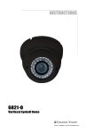
1
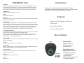
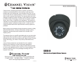
1
Channel Vision Technology will repair or replace any defect in
material or workmanship which occurs during normal use of this
product with new or rebuilt parts, free of charge in the USA, for one
year from the date of original purchase. This is a no hassle warranty
with no mail in warranty card needed. This warranty does not cover
damages in shipment, failures caused by other products not supplied
by Channel Vision Technology, or failures due to accident, misuse,
abuse, acts of God, or alteration of the equipment. This warranty is
extended only to the original purchaser when purchased through an
authorized reseller. A purchase receipt, invoice, or other proof of
original purchase date will be required before warranty repairs are
provided.
Mail in service can be obtained during the warranty period by calling
(800) 840-0288 toll free. A Return Authorization number must be
obtained in advance and can be marked on the outside of the
shipping carton.
This warranty gives you specific legal rights and you may have other
rights (which vary from state to state). If a problem with this product
develops during or after the warranty period, please contact Channel
Vision Technology, your dealer or any factory-authorized service
center.
Channel Vision products are not intended for use in medical,
lifesaving, life sustaining or critical environment applications.
Channel Vision customers using or selling Channel Vision products
for use in such applications do so at their own risk and agree to fully
indemnify Channel Vision for any damages resulting from such
improper use or sale.
6810-O
Mini Varifocal Eyeball Dome Camera
www.channelvision.com
234 Fischer Avenue, Costa Mesa, California 92626 USA
(714)424-6500 (800)840-0288 (714)424-6510 fax
email: [email protected]
500-328 Rev C
12
Safety Warnings
Specifications
*Specifications:
Image Sensor:
Sony 1/3” Hi-Res Effio-E
Picture Elements:
NTSC: 811 (H) x 508 (V)
Resolution:
700 lines
S/N Ratio:
More than 48 dB
Min Illumination:
0 LUX (IR on)
Gamma Characteristic:
0.45
3. Heed all warnings.
Auto Electronic Shutter:
Auto, 1/50 (1/60) - 1/100,000 Sec
AGC:
Built in
4. Follow all instructions.
Camera Lens:
3.6mm
IMPORTANT SAFETY INSTRUCTIONS
1. Read these instructions.
2. Keep these instructions for future reference.
5. Clean only with a dry cloth.
6. Install in accordance with these instructions.
7 Do not install near any heat sources such as radiators, heat
registers, stoves, or other apparatus that produce heat.
8. Only use attachments/accessories specified by Channel Vision.
Sync. System:
Internal, Negative sync.
Power Requirements:
12VDC 196mA (IR off) 250mA (IR on)
Infrared Illumination:
26 IR LEDs
LED Wavelength:
850nm
Illumination Distance:
12 meters (40ft)
Video Output:
1 Vp-p @ 75 ohms
Weatherproof Rating:
IP66
Operating Temp:
-10°C to 50°C (14°F to 122°F)
Power Supply Connector Size:
2.1mm
9. Unplug this apparatus during lightning storms.
*Specifications subject to change without notice.
10. Refer all servicing to qualified service personnel.
Servicing is required when the apparatus has been damaged in
any way, such as power supply cord or plug is damaged, liquid
has been spilled or objects have fallen into the apparatus, the
inside of the apparatus has been exposed to rain or moisture,
does not operate normally, or has been dropped.
11. Inside of apparatus shall not be exposed to dripping, splashing
or objects filled with liquids.
2
Troubleshooting
Symptoms
No Video
Video cuts in & out
Snow on image
Poor quality image
Troubleshooting Steps
1. Verify power supply is 12vDC with volt meter
2. Bypass cable (coax cable)
3. Verify camera has power by placing your finger over the IR sensor
and look for the red IR illuminator glow
4. Reset camera settings to factory default with the OSD
5. Verify cable with white strip is on the center (+) side of the connector
6. Separate center pin of power supply connector and confirm it is
making contact
Video is washed out
looking at a bright
object such as a light
or the sun
1. Turn on HLC (High Light Compensation) in the OSD
2. Turn on D-WDR (Digital Wide Dynamic Range) in the OSD
Video is hard to see at
night, or image does
not appear illuminated
enough
1. Turn on BLC (Back Light Compensation) in the OSD
2. Adjust brightness in the Picture Adjustment menu in the OSD
3. Verify Day/Night mode in the OSD. It should be on Automatic
4. Point camera away from bright light as it may be shutting down the iris
7
Introduction
OSD SETUP Cont.
6. D-WDR
Select to adjust D-WDR modes. In this menu you may turn Digital WDR on or off.
The wide dynamic range function of a camera is intended to provide clear images
even under back light circumstances where intensity of illumination can vary when
there are both very bright and very dark areas simultaneously in the field of view.
7. Motion Det
Select to turn Motion Detection on or off.
Thank you for purchasing Channel Vision's 6810-O high
resolution dome camera. Please take the time to read over these
instructions to ensure proper installation and usage.
8. Next
Select to enter next menu.
Features
9. Privacy
Select to turn privacy on or off. Privacy can block out certain portions of the image to
someone viewing the picture.
10. Day/Night
Select to adjust Day/Night mode. The following options are available: EXT1, EXT2,
Black and White, Color, or Automatic. EXT1 and EXT2 are reserved. Black and white
will force the camera into black and white mode. Color will force the camera into color
mode. Automatic is the ideal setting, as the camera with automatically change it’s
mode according to lighting conditions. For the IR illuminators to work properly, the
camera will change to black and white during night and low light viewing.
• Outdoor 1/3" High Resolution CCD Sensor
• 700 TV Lines
• 0 Lux (IR On) 26 LED’s
• On Screen Display (OSD)
11. NR (Noise Reduction)
All electronic devices, both analog or digital, have traits which make them susceptible
to noise, which can show up as “snow” on the video images.
In this menu you may adjust Noise Reduction from off to Y/C, in which you can
manually adjust Y and C separately. This can help compensate for noise in your
video image. Y and C are calibration values.
Box Contents
12. Camera ID
Select to turn camera ID off or on. This will display a Camera ID on the screen, along
with your video image.
13. Sync
This is set to internal and cannot be changed.
Items Included:
6810-O
(1) 6810-O camera
(4) Mounting screws
(1) Allen wrench
14. Language
Select to change language. This allows changing to a variety of different languages:
Chinese, English, German, French, Spanish, & Portugese.
Tools & Accessories
Required (Not included):
15. Camera Reset
Select to reset camera. Note: this can not be reversed, and will reset all custom
settings to factory default.
16. Back
Select to go return to previous menu.
17. Exit
Select to Exit.
6
(4) Screws
(1) 12vDC power supply
(400mA or higher)
(1) Wire stripper
(1) Small flathead screwdriver
(1) Phillips screwdriver
3
Installation
OSD Setup
Menu Operation Instructions
Video
(BNC Connector)
Coax extension
(not included)
To enter OSD programming mode, press in on the joystick, located on the camera pigtail.
The on-screen arrow points to the selected option. Using the joystick, navigate left, right,
up or down to change the value of your selection or enter the submenu for the selected
option. Press “Exit” or “Return” to return to the previous menu. (One layer up).
OSD Setup
Joystick
for OSD
Power
2-Conductor power
supply extension
(not included)
Crimp-on splice
connectors
(not included)
To Monitor
or
Video distribution
Power supply
(not included)
6810-O
Related Products
• 4, 8 & 16 channel options
• 3G mobile phone streaming video to
iPhone®, Blackberry®, Android® &
Windows® Mobile
• Internet viewing through Internet
Explorer®
• Simultaneous real time output on VGA & BNC
DVR-43G, DVR-83G, DVR-163G
• Audio input and output
• Video, audio & power over 1,000 ft. of CAT5
1. Lens/Auto Iris
An Auto Iris lens is a lens in which the aperture automatically opens or closes to maintain
the proper light levels. This feature can be used to adjust operation of the lens and how it
responds to light. Once in manual mode, you can choose to open or close the iris, as well
as adjust the speed, if you have controlled lighting conditions.
2. Shutter/AGC
The following modes are available in High Luminance: Shutter + Auto Iris, or Auto Iris
only. For Low Luminance, you can choose the following: On (AGC on) or Off (AGC off)
You may also adjust brightness from x0.25 to x1.00.
AGC (Automatic Gain Control) is an electronic circuit designed for automatically
controlling amplifier gain in order to maintain a constant output voltage with a varying
input voltage within a predetermined range of input-to-output variation. AGC is generally
best utilized in an indoor room that has a lower light level than the other rooms in the
building or when light cannot be increased enough for a good usable picture. AGC should
be set to off first. However, it can be activated after the iris is adjusted.
3. White Bal
Select to change white balance mode. In this menu you may change the speed, delay,
and adjust ATW frame from x1.00 to x2.00. In this menu, you may also manually select
the environment mode from indoor to outdoor. This controls the color balance of the
camera.
4. Backlight
Select to adjust backlight. In this menu you may change the mode from
HLC to BLC. HLC stands for High Light Compensation, and it has the ability to reverse
bright points in the picture to black. HLC improves the ability of the entire system
to display shades of grey elsewhere in the picture. BLC stands for Back Light
Compensation, and automatically adjusts picture brightness depending on lighting
conditions. This helps overcome strong backlighting which normally results in silhouettes
or shadows. BLC can help correct the exposure of subjects that are in front of a bright
light source.
5. Pict Adjust
Select to enter picture adjustment menu. In this menu you may mirror the image, adjust
the brightness, contrast, sharpness, hue and gain.
B-300 Video Balun Kit
4
5